


Billion BiPAC SHDSL/SHDSL.bis (VPN) Firewall Bridge/ Router
BiPAC 8500/8520
SHDSL VPN Firewall Bridge/ Router
BiPAC 8501/8521
SHDSL.bis (VPN) Firewall Bridge/Router
User Manual
Last revision 11-08-08

Billion BiPAC SHDSL/SHDSL.bis (VPN) Firewall Bridge/ Router
TTaabbllee ooff CCoonntteennttss
CCHHAAPPTTEERR 11:: IINNTTRROODDUUCCTTIIOONN..........................................................................................................................................................................................................................1
I
NTRODUCTION TO YOUR ROUTER
F
EATURES
............................................................................................................................................. 1
........................................................................................................ 1
CCHHAAPPTTEERR 22:: IINNSSTTAALLLLIINNGG TTHHEE RROOUUTTEERR..................................................................................................................................................................................4
I
MPORTANT NOTE FOR USING THIS ROUTER
P
ACKAGE CONTENTS
T
HE FRONT
T
HE FRONT
T
HE FRONT
T
HE FRONT
T
HE REAR PORTS OF BI
T
HE REAR PORTS OF BI
T
HE REAR PORTS OF BI
LED
LED
LED
LED
............................................................................................................................ 4
S OF BI
S OF BI
S OF BI
S OF BI
PAC 8500....................................................................................................... 5
PAC 8520....................................................................................................... 6
PAC 8501....................................................................................................... 7
PAC 8521....................................................................................................... 8
PAC 8500 / 8520 ............................................................................................. 9
PAC 8501...................................................................................................... 10
PAC 8521.......................................................................................................11
.......................................................................................... 4
1
4
C
ABLING
............................................................................................................................................ 12
CCHHAAPPTTEERR 33:: BBAASSIICC IINNSSTTAALLLLAATTIIOONN................................................................................................................................................................................................113
C
ONNECTING YOUR ROUTER
.............................................................................................................. 13
Network Configuration................................................................................................................. 14
F
ACTORY DEFAULT SETTINGS
............................................................................................................. 23
Web Interface (Username and Password): ................................................................................... 23
Device LAN IP Settings:.............................................................................................................. 23
ISP setting in WAN site:............................................................................................................... 23
DHCP server:................................................................................................................................ 23
LAN and WAN Port Addresses .................................................................................................... 23
I
NFORMATION FROM YOUR
C
ONFIGURING WITH YOUR WEB BROWSER
ISP........................................................................................................... 24
........................................................................................ 25
CCHHAAPPTTEERR 44:: CCOONNFFIIGGUURRAATTIIOONN..................................................................................................................................................................................................................226
S
TATUS
............................................................................................................................................... 27
ARP Table..................................................................................................................................... 27
Routing Table ............................................................................................................................... 28
3
6
DHCP Table.................................................................................................................................. 29
PPTP Status (BiPAC 8500/ 8501/ 8520 Only) ............................................................................. 30
IPSec Status (BiPAC 8500/ 8501/ 8520 Only)............................................................................. 31
L2TP Status (BiPAC 8500/ 8501/ 8520 Only) ............................................................................. 32
Email Status.................................................................................................................................. 32
Event Log ..................................................................................................................................... 33
Error Log ...................................................................................................................................... 33
i

NAT Sessions ............................................................................................................................... 34
Diagnostic..................................................................................................................................... 34
UPnP Portmap .............................................................................................................................. 35
Q
UICK START
C
ONFIGURATION
..................................................................................................................................... 36
................................................................................................................................ 38
LAN (Local Area Network) ......................................................................................................... 38
WAN (Wide Area Network) ......................................................................................................... 46
System .......................................................................................................................................... 74
Firewall and Access Control......................................................................................................... 80
VPN (Virtual Private Networks) (BiPAC 8500/ 8501/ 8520 Only) ............................................. 97
QoS (Quality of Service)............................................................................................................ 136
Virtual Server (“Port Forwarding”)............................................................................................ 144
Time Schedule............................................................................................................................ 151
Advanced.................................................................................................................................... 153
S
AVE CONFIGURATION TO FLASH
..................................................................................................... 165
L
OGOUT
........................................................................................................................................... 165
CCHHAAPPTTEERR 55:: TTRROOUUBBLLEESSHHOOOOTTIINNGG................................................................................................................................................................................................11666
AAPPPPEENNDDIIXX AA:: PPRROODDUUCCTT SSUUPPPPOORRTT AANNDD CCOONNTTAACCTT IINNFFOORRMMAATTIIOONN........................................................................11667
6
7
ii


Billion BiPAC 8500/8501/8520/8521 SHDSL (VPN) Firewall Bridge/ Router
Chapter 1: Introduction
Introduction to your Router
Welcome to the Billion BiPAC 8500/ 8501/ 8520/ 8521 SHDSL Router. Your SHDSL router is an
“all-in-one” unit, combining an SHDSL modem, SHDSL router and Ethernet network switch,
providing everything you need to get the machines on your network connected to the Internet
over your SHDSL broadband connection. With features such as an SHDSL Quick-Start wizard
and DHCP Server, you can be online in no time at all and with minimum fuss and configuration,
catering for both first-time users and professionals who require advanced features to control
their Internet connection and network.
Features
SHDSL Multi-Mode Standard
BiPAC 8500 / 8520 SHDSL supports downstream and upstream transmission rates of up
to 2.3 / 4.6 Mbps, respectively, and BiPAC 8501 SHDSL.bis can support up to 5.7 Mbps
on 2-wire and 8521 SHDSL.bis can support up to 11.4 Mbps on 4-wire. BiPAC 85xx
series also supports rate management that allows SHDSL subscribers to select an
Internet access speed suiting their needs and budgets. BiPAC 8500/ 8520 and 8501/
8521 follows ITU standard PAM16 Line Code complies with G.991.2 and G.994.1
standards, and BiPAC 8501 follows PAM 32 Line code with G.991.2 and G.991.2.bis
standards. These three models can support Annex A and B operating mode.
Fast Ethernet Switch
A 4-port 10/100Mbps fast Ethernet switch is built in with automatic switching between
MDI and MDI-X for 10Base-T and 100Base-TX ports. An Ethernet straight or crossover
cable can be used directly for auto detection.
Multi-Protocol to establish a connection
It supports PPPoA (RFC 2364 - PPP over ATM Adaptation Layer 5), RFC 1483
encapsulation over ATM (bridged or routed), PPP over Ethernet (RFC 2516), and IPoA
(RFC1577) to establish a connection with the ISP. The product also supports VC-based
and LLC-based multiplexing.
Quick Installation Wizard
It supports a WEB GUI page to install this device quickly. With this wizard, end users not
only can enter the information they get from their ISP easily, it also enables immediate
internet suffing.
Universal Plug and Play (UPnP) and UPnP NAT Traversal
This protocol is used to enable simple and robust connectivity among stand-alone
devices and PCs from many different vendors. It makes networking simple and
affordable for users. UPnP architecture leverages TCP/IP and the Web to enable
seamless proximity networking in addition to controling data transfer among networked
Chapter 1: Introduction
1

Billion BiPAC 8500/8501/8520/8521 SHDSL (VPN) Firewall Bridge/ Router
devices. With this feature enabled, users can now connect to Net meeting or MSN
Messenger seamlessly.
Network Address Translation (NAT)
Allows multi-users to access outside resources such as the Internet simultaneously with
one IP address/one Internet access account. Many application layer gateways (ALG) are
supported such as web browser, ICQ, FTP, Telnet, E-mail, News, Net2phone, Ping,
NetMeeting, IP phone and others.
SOHO Firewall Security with DoS and SPI
Along with the built-in NAT natural firewall feature, the router also provides advanced
hacker pattern-filtering protection. It can automatically detect and block Denial of Service
(DoS) attacks. The router is built with Stateful Packet Inspection (SPI) to determine if a
data packet is allowed access to the private LAN through the firewall.
Domain Name System (DNS) relay
It provides an easy way to map the domain name (a friendly name for users such as
www.yahoo.com) and IP address. When a local machine sets its DNS server with this
router IP address, every DNS conversion request packet from the PC to this router will
be forwarded to the real DNS of an outside network.
Dynamic Domain Name System (DDNS)
The Dynamic DNS service allows you to alias a dynamic IP address to a static hostname.
This dynamic IP address is the WAN IP address. For example, to use the service, you
must first apply for an account from a DDNS service like http://www.dyndns.org/. More
than 5 DDNS servers are supported.
Quality of Service (QoS)
QoS gives you full control over which type of outgoing data traffic should be given priority
by the router, ensuring important data like gaming packets, customer information, or
management information move through the router speed fast, even under heavy load.
The QoS features are configurable by source IP address, destination IP address,
protocol, and port. You can throttle the speed of different types of outgoing data passing
through the router to ensure P2P users don’t saturate the upload bandwidth, or office
browsing doesn’t bring client web serving to a halt. Alternatively, you can simply change
the priority of different types of upload data and let the router sort out the actual speeds
of each data transmission.
Virtual Private Network (VPN) (BiPAC 8500/ 8501/ 8520 Only)
It allows user to establish a virtual network with a remote computer. In this way data can
be transmitted securedly through the virtual tunnel formed within the network. User can
use embedded PPTP and L2TP client/server, IKE and IPSec which are supported by this
router to make a VPN connection or run the PPTP client in PC and the router which
provides IPSec and PPTP pass through function to establish a VPN connection if the
user likes to run the PPTP client in his local computer.
Virtual Server (“port forwarding”)
Users can specify some services to be visible from outside users. The router can detect
incoming service requests and forward either a single port or a range of ports to specific
local computer for handling. For example, a user can assign a PC in the LAN acting as a
WEB server inside and expose it to the outside network. Outside users can browse
inside web servers directly while it is protected by NAT. A DMZ host setting is also
provided to a local computer exposed to the outside network, Internet.
Chapter 1: Introduction
2

Billion BiPAC 8500/8501/8520/8521 SHDSL (VPN) Firewall Bridge/ Router
Rich Packet Filtering
Not only filters the packet based on IP address, but also based on Port numbers. It will
filter packets from and to the Internet. It also provides a higher level of security control.
Dynamic Host Configuration Protocol (DHCP) client and server
In the WAN site, the DHCP client can get an IP address from the Internet Service
Provider (ISP) automatically. In the LAN site, the DHCP server can allocate a range of
client IP addresses including IP address, subnet mask as well as DNS IP address and
distribute them to local computers. It provides an easy way to manage the local IP
network.
Static and RIP1/2 Routing
It has routing capability and supports easy static routing table or RIP1/2 routing protocol.
Simple Network Management Protocol (SNMP)
It is an easy way to remotely manage the router via SNMP.
Web based GUI
It supports web based GUI for configuration and management. It is user-friendly and
comes with on-line help. It also supports remote management capability for remote users
to configure and manage this product.
Firmware Upgradeable
Device can be upgraded to the latest firmware through the WEB based GUI.
Rich Management Interfaces
It supports flexible management interfaces with local console port, LAN port, and WAN
port. Users can use terminal applications through the console port to configure and
manage the device, or Telnet, WEB GUI, and SNMP through LAN or WAN ports to
configure and manage the device.
Chapter 1: Introduction
3
Billion BiPAC 8500/8501/8520/8521 SHDSL (VPN) Firewall Bridge/ Router
Only use the power adapter that comes with the package. Using
Important note for using this Router
Warning
Attention
Do not use the router in high humidity or high temperatures.
Do not use the same power source for the router as other
equipment.
Do not open or repair the case yourself. If the router is too
hot, turn off the power immediately and have it repaired at a
qualified service center.
Avoid using this product and all accessories outdoors.
Place the router on a stable surface.
a different voltage rating power adaptor may damage the router.
Chapter 2: Installing the Router
Package Contents
SHDSL Firewall Bridge/Router (BiPAC 8500/8520) or SHDSL.bis Firewall Bridge/Router
(BiPAC 8501/8521)
CD-ROM containing the online manual
RJ-11 SHDSL/telephone Cable (One Cable for BiPAC 8500/8501) (Two Cables for
BiPAC 8520/8521)
Ethernet (CAT-5 LAN) Cable
Console (PS2-RS232) Cable
AC-DC power adapter (12V DC, 1A)
Quick Start Guide
Chapter 2: Installing the router
4
Billion BiPAC 8500/8501/8520/8521 SHDSL (VPN) Firewall Bridge/ Router
2
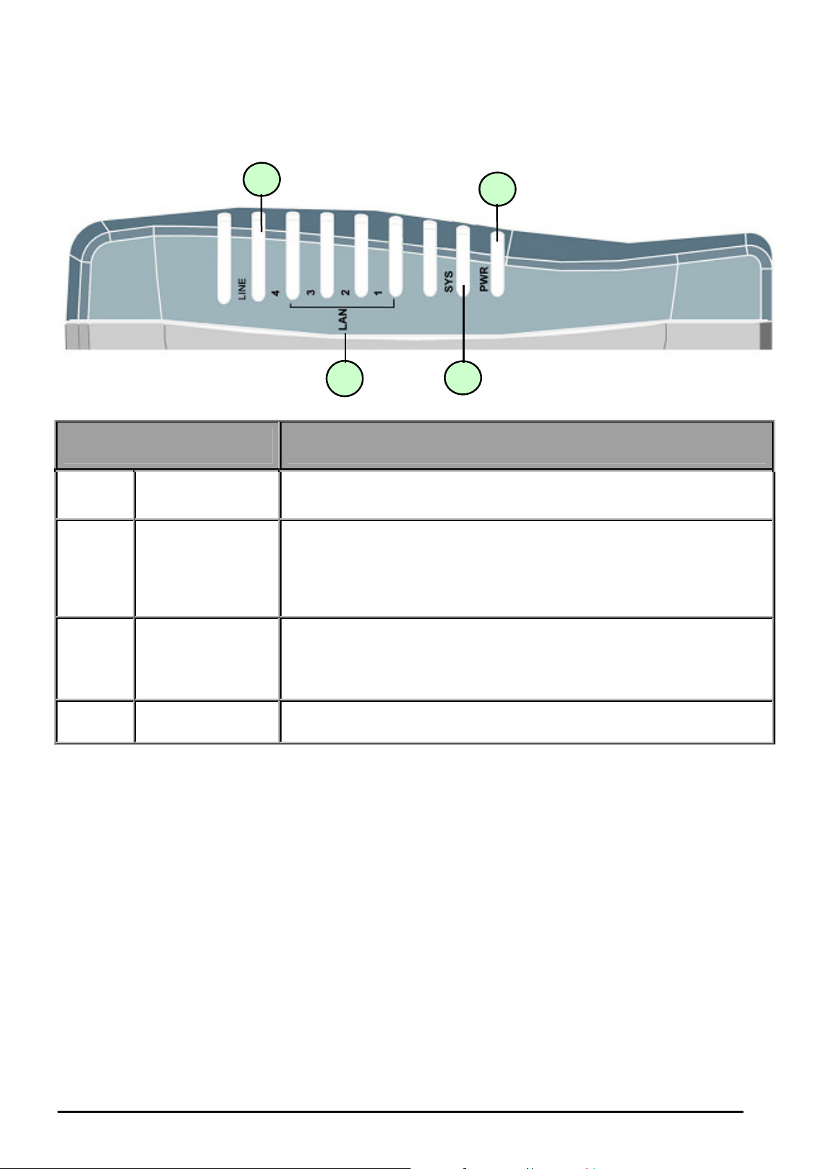
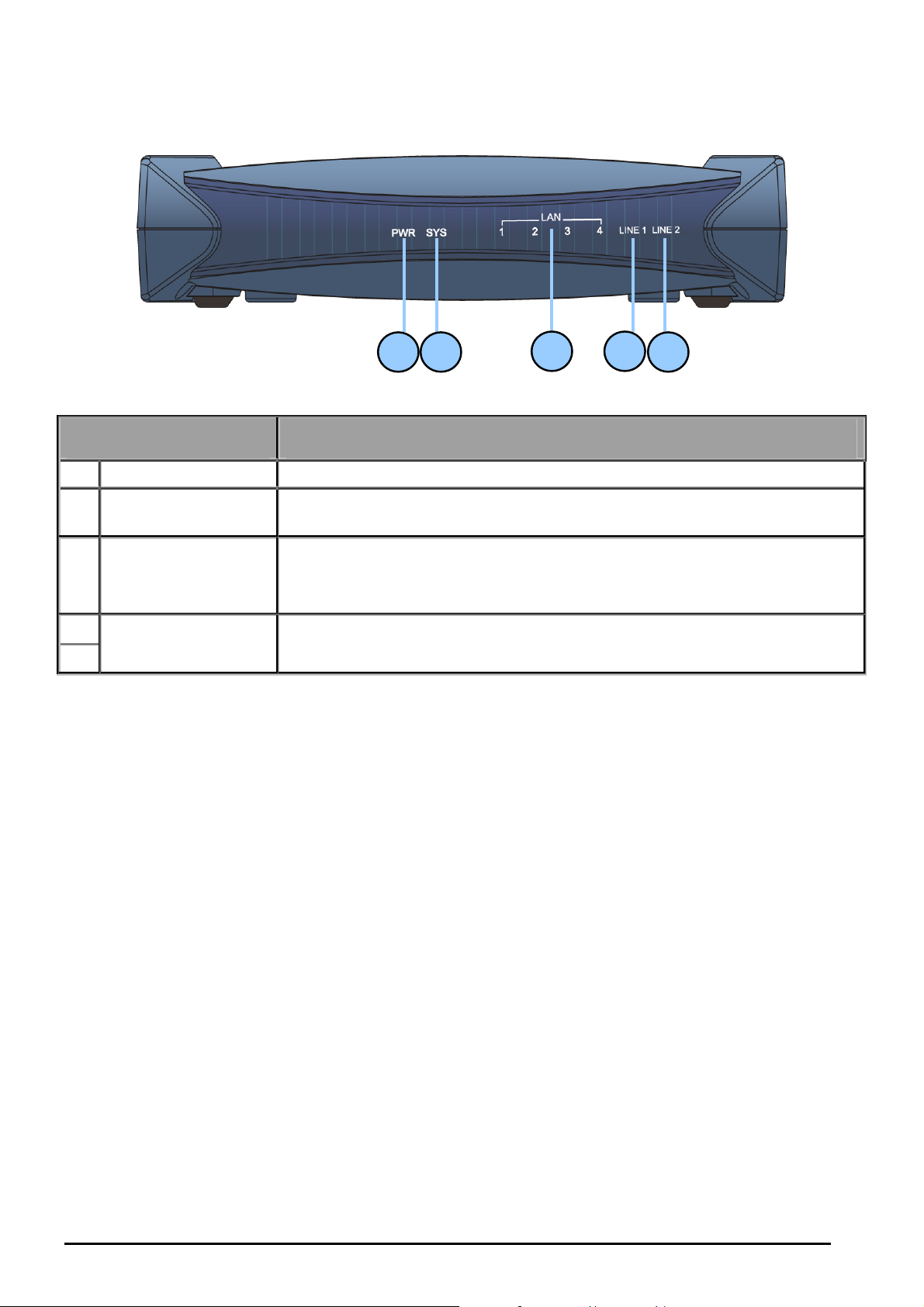
The Front LEDs of BiPAC 8500
LED Meaning
1 LINE
LAN Port
2
1X — 4X
(RJ-45 connector)
Lit when successfully connected to SHDSL line and when it is
synchronized.
Lit when connected to an Ethernet device.
Green for 100Mbps; Orange for 10Mbps.
Blinking when data is Transmitted / Received.
3 SYS Lit when the system is ready.
4 PWR Lit when power is ON.
Chapter 2: Installing the router
5
Billion BiPAC 8500/8501/8520/8521 SHDSL (VPN) Firewall Bridge/ Router
3
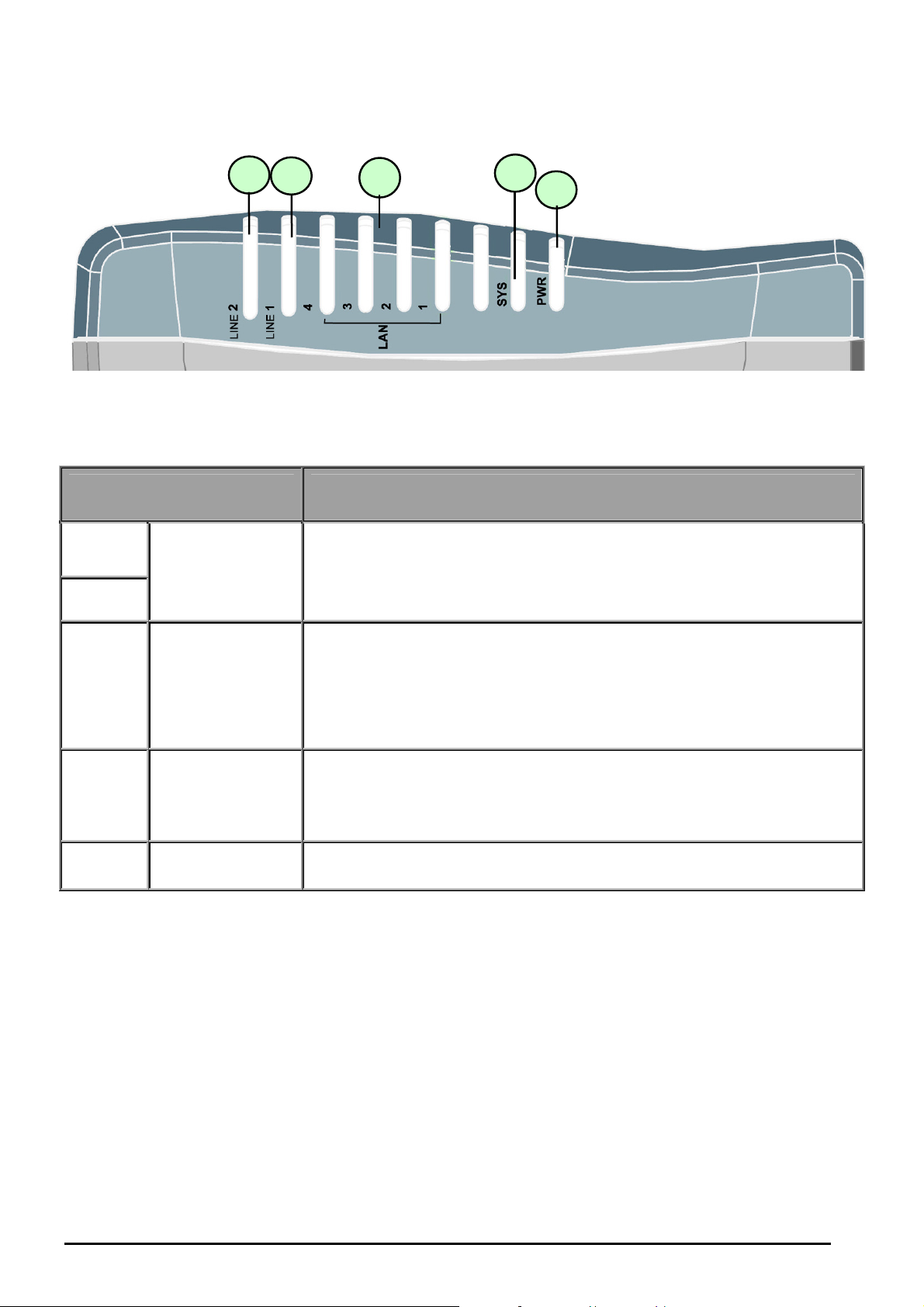
The Front LEDs of BiPAC 8520
LED Meaning
1
LINE 1 & 2
2
Lit when successfully connected to SHDSL line and when it is
synchronized.
3
LAN Port
1X — 4X
(RJ-45 connector)
Lit when connected to an Ethernet device.
Green for 100Mbps; Orange for 10Mbps.
Blinking when data is Transmitted / Received.
4 SYS Lit when the system is ready.
5 PWR Lit when power is ON.
Chapter 2: Installing the router
6
Billion BiPAC 8500/8501/8520/8521 SHDSL (VPN) Firewall Bridge/ Router
3
2
1
4
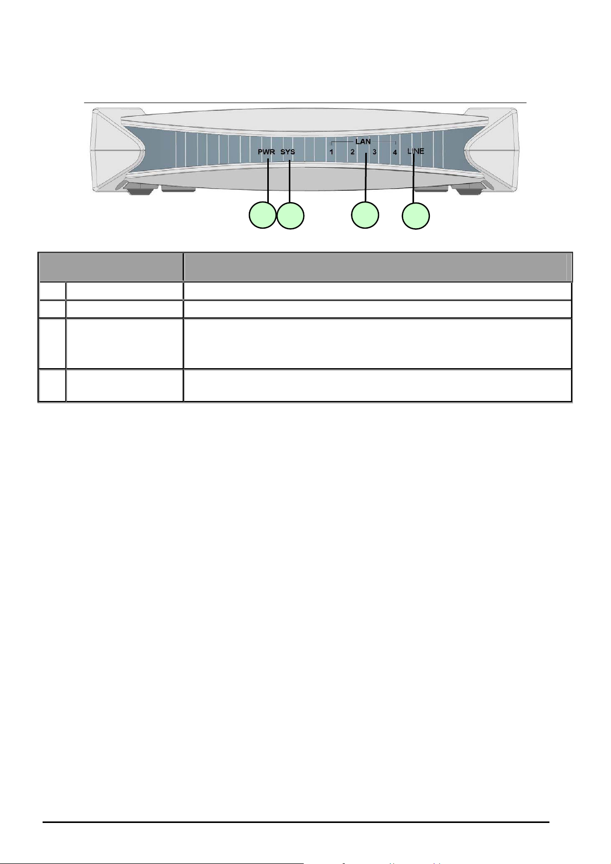
The Front LEDs of BiPAC 8501
LED Meaning
1 PWR Lit when power is ON.
2 SYS Lit when the system is ready.
LAN Port
3
1X — 4X
(RJ-45 connector)
4 LINE
Lit when connected to an Ethernet device.
Green for 100Mbps; Orange for 10Mbps.
Blinking when data is Transmitted / Received.
Lit when successfully connected to SHDSL line and when it is
synchronized.
Chapter 2: Installing the router
7
Billion BiPAC 8500/8501/8520/8521 SHDSL (VPN) Firewall Bridge/ Router
1 2 3 4 5
The Front LEDs of BiPAC 8521
LED Meaning
1 PWR Lit green when power is ON.
2 SYS
LAN Port
3
1X — 4X
(RJ-45 connector)
4
LINE 1 & 2
5
Flashes when the system is being started. Then lit green when the
system is ready.
Lit when connected to an Ethernet device.
Green for 100Mbps; Orange for 10Mbps.
Blinking when data is Transmitted / Received.
The green LED will flash steadily when successfully connected to
SHDSL line and when it is synchronized.
Chapter 2: Installing the router
8
Billion BiPAC 8500/8501/8520/8521 SHDSL (VPN) Firewall Bridge/ Router
1
2
3
4
5
6
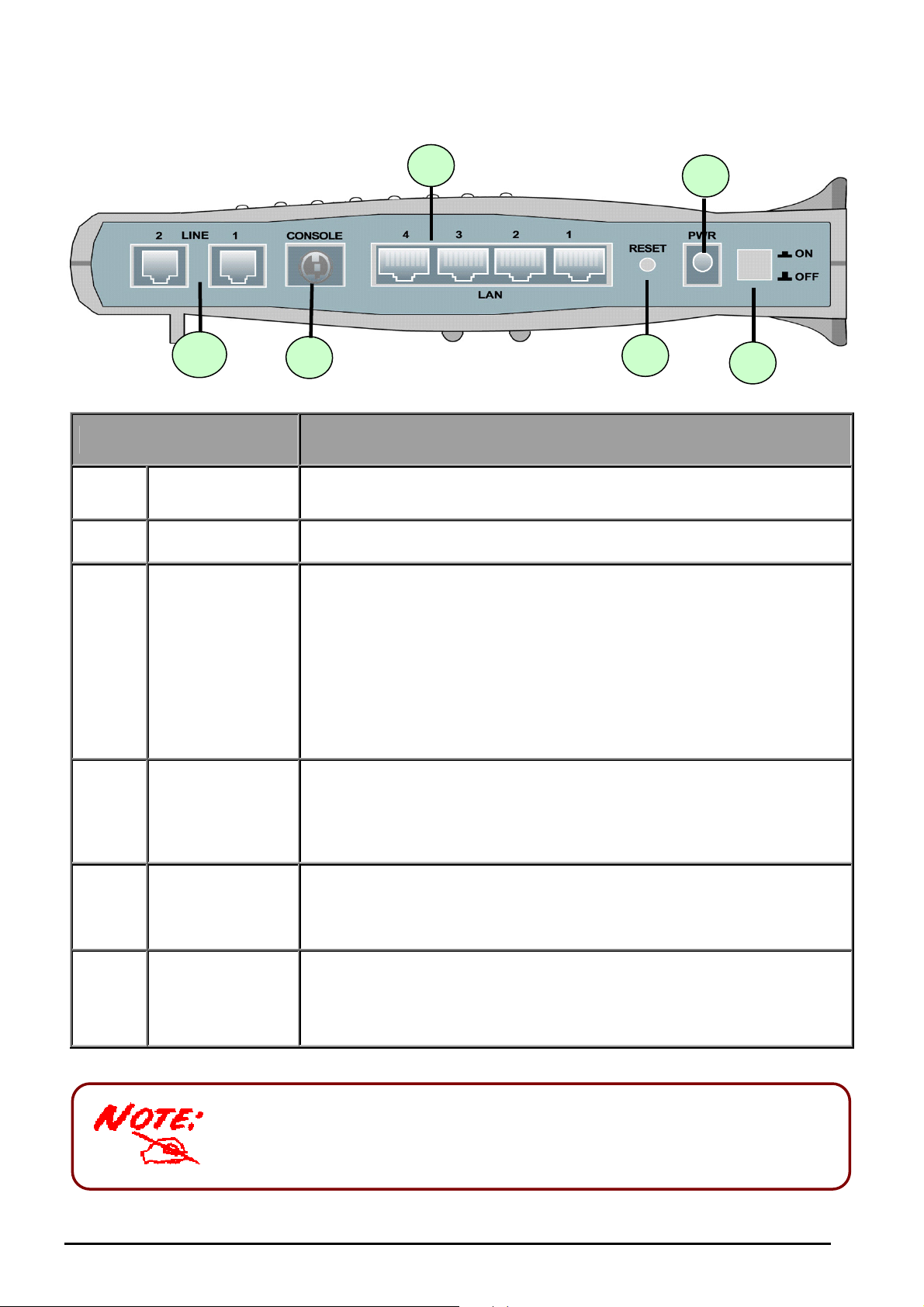
The Rear Ports of BiPAC 8500 / 8520
Port Meaning
1
2
3
4
5
Power Switch Power ON/OFF switch
PWR Connect the supplied power adapter to this jack.
To be sure the device is being turned on press RESET button
for:
1-3 seconds: quick reset the device.
6 seconds above, and power off, power on the device:
RESET
LAN
1X — 4X
(RJ-45 connector)
CONSOLE
restore to factory default settings. (Cannot login to the router or
forgot your Username/Password. Press the button for more than
6 seconds).
Caution: After pressing the RESET button for more than 6
seconds, to be sure you power cycle the device again.
Connect a UTP Ethernet cable (Cat-5 or Cat-5e) to one of the
four LAN ports when connecting to a PC or an office/home
network of 10Mbps or 100Mbps.
Connect a PS2/RS-232 cable to this port when connecting to a
PC’s RS-232 port (9-pin serial port).
LINE
6
Only BiPAC 8520 has two Line jack ports. BiPAC 8500 has one.
.
Chapter 2: Installing the router
1X — 2X
(RJ-11 connector)
Connect the supplied RJ-11 (“telephone”) cable to this port when
connecting to the SHDSL line.
9
Billion BiPAC 8500/8501/8520/8521 SHDSL (VPN) Firewall Bridge/ Router
3 1
2 4 6
5
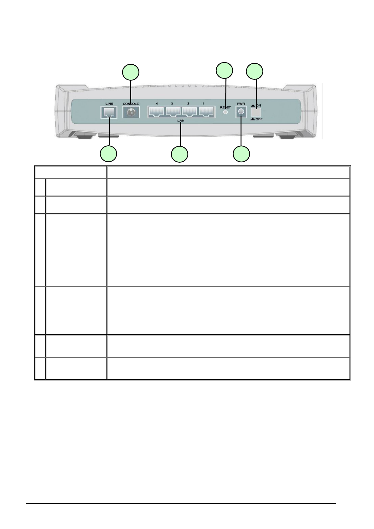
The Rear Ports of BiPAC 8501
Port Meaning
1 Power Switch Power ON/OFF switch
2 PWR Connect the supplied power adapter to this jack.
3 RESET
LAN
4
1X — 4X
(RJ-45 connector)
5 CONSOLE
6 LINE
To be sure the device is being turned on->press RESET button for:
1-3 seconds: quick reset the device.
6 seconds above, and power off, power on the device: restore to
factory default settings. (Cannot login to the router or forgot your
Username/Password. Press the button for more than 6 seconds).
Caution: After pressing the RESET button for more than 6 seconds, to
be sure you power cycle the device again.
Connect a UTP Ethernet cable (Cat-5 or Cat-5e) to one of the four
LAN ports when connecting to a PC or an office/home network of
10Mbps or 100Mbps.
Connect a PS2/RS-232 cable to this port when connecting to a PC’s
RS-232 port (9-pin serial port).
Connect the supplied RJ-11 (“telephone”) cable to this port when
connecting to SHDSL line.
Chapter 2: Installing the router
10
Billion BiPAC 8500/8501/8520/8521 SHDSL (VPN) Firewall Bridge/ Router
3 1 2
4 6
5
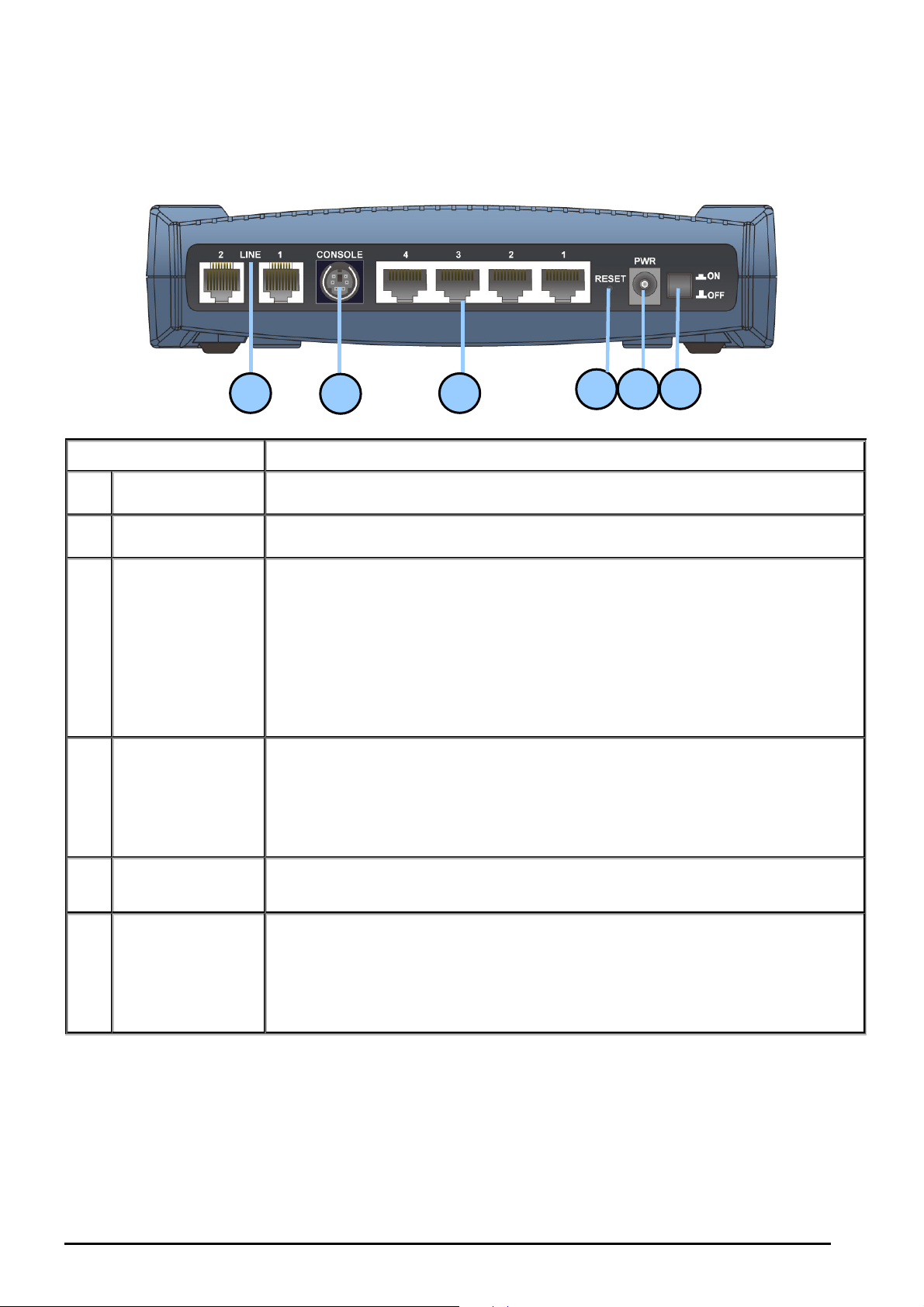
The Rear Ports of BiPAC 8521
Port Meaning
1 Power Switch Power ON/OFF switch
2 PWR Connect the supplied power adapter to this jack.
To be sure the device is being turned on->press RESET button for:
1-3 seconds: quick reset the device.
Press 6 seconds above to power off the device, then power on the
3 RESET
device to restore the factory default settings. (Used when cannot login
to the router or forgot your Username/Password. Press the button for
more than 6 seconds).
Caution: After pressing the RESET button for more than 6 seconds, to
be sure you power cycle the device again.
LAN
Connect a UTP Ethernet cable (Cat-5 or Cat-5e) to one of the four
4
1X — 4X
LAN ports when connecting to a PC or an office/home network of
10Mbps or 100Mbps.
(RJ-45 connector)
Connect a PS2/RS-232 cable to this port when connecting to a PC’s
5 CONSOLE
RS-232 port (9-pin serial port).
LINE
Connect the supplied RJ-11 (“telephone”) cable to this port when
6
1X — 2X
connecting to SHDSL line.
(RJ-11 connector)
11
Chapter 2: Installing the router

Billion BiPAC 8500/8501/8520/8521 SHDSL (VPN) Firewall Bridge/ Router
Cabling
One of the most common causes to problem is bad cabling or SHDSL line(s). Make sure that all
connected devices are turned on. On the front panel of the product is a row of LEDs. Verify that
the LAN Link and SHDSL line LEDs are lit. If they are not, verify that you are using the proper
cables.
Chapter 2: Installing the router
12

Billion BiPAC SHDSL/SHDSL.bis (VPN) Firewall Bridge/ Router
Chapter 3: Basic Installation
The router can be configured with your web browser. A web browser is included as a standard
application in the following operating systems: Linux, Mac OS, Windows 98/NT/2000/XP/Me,
etc. The product provides an easy and user-friendly interface for configuration.
Please check your PC’s network components. The TCP/IP protocol stack and Ethernet network
adapter must be installed. If not, please refer to your Windows-related or other operating
system manuals.
There are ways to connect to the router, either through an external repeater hub to the router or
directly connecting with PCs. However, to be sure PCs have an Ethernet interface installed
properly prior to connecting to the router. You ought to configure your PCs to obtain an IP
address through a DHCP server or a fixed IP address that must be in the same subnet as the
router. The default IP address of the router is 192.168.1.254 and the subnet mask is
255.255.255.0 (i.e. any attached PC must be in the same subnet, and have an IP address in the
range of 192.168.1.1 to 192.168.1.253). The best and easiest way is to configure the PC to get
an IP address automatically from the router using DHCP. If you encounter any problem
accessing the router’s web interface it may also be advisable to uninstall any kind of software
firewall on your PCs, as they can cause problems accessing the 192.168.1.254 IP address of
the router. Users should make their own decisions on how to best protect their network.
Please follow the steps below for your PC’s network environment installation.
Any TCP/IP capable workstation can be used to communicate with or
through the SHDSL Router. To configure other types of workstations, please
consult the manufacturer’s documentation.
Connecting your router
1. Connect the Router to a LAN (Local Area Network) and the SHDSL LINE.
2. Power on the device.
3. Make sure the PWR and SYS LEDs are lit steadily and that the relevant LAN LED are lit.
Chapter 3: Basic Installation
13

Billion BiPAC SHDSL/SHDSL.bis (VPN) Firewall Bridge/ Router
Network Configuration
For Windows Vista
1. Go to Start. Click on
Network.
2. Then click on Network and
Sharing Center at the top
bar.
3. When the Network and
Sharing Center window
pops up, select and click on
Manage network
connections on the left
window pane.
4. Select the Local Area
Connection, and right click
the icon to select
Properties.
Chapter 3: Basic Installation
14
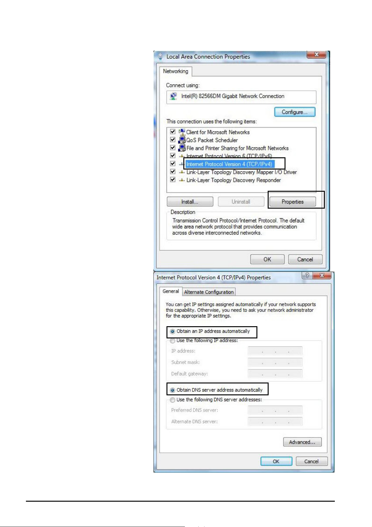
5. Select Internet Protocol
Version 4 (TCP/IPv4) then
click Properties.
Billion BiPAC 8500/8501/8520/8521 SHDSL (VPN) Firewall Bridge/ Router
6. In the TCP/IPv4 properties
window, select the Obtain
an IP address
automatically and Obtain
DNS Server address
automatically radio
buttons. Then click OK to
exit the setting.
7. Click OK again in the Local
Area Connection
Properties window to apply
the new configuration.
Chapter 3: Basic Installation
15
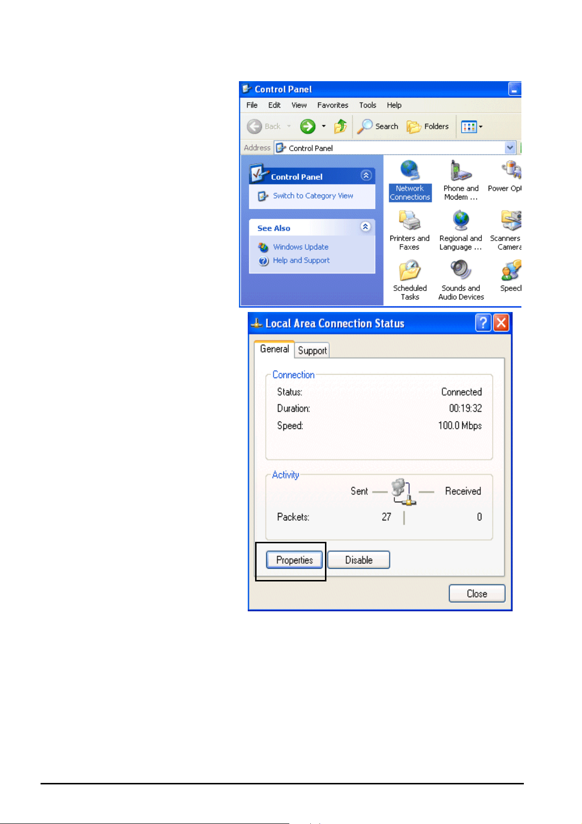
For Windows XP
1. Go to Start / Control Panel
(in Classic View). In the
Control Panel, double-click
on Network Connections
2. Double-click Local Area
Connection.
3. In the Local Area
Connection Status window,
click Properties.
Billion BiPAC 8500/8501/8520/8521 SHDSL (VPN) Firewall Bridge/ Router
Chapter 3: Basic Installation
16
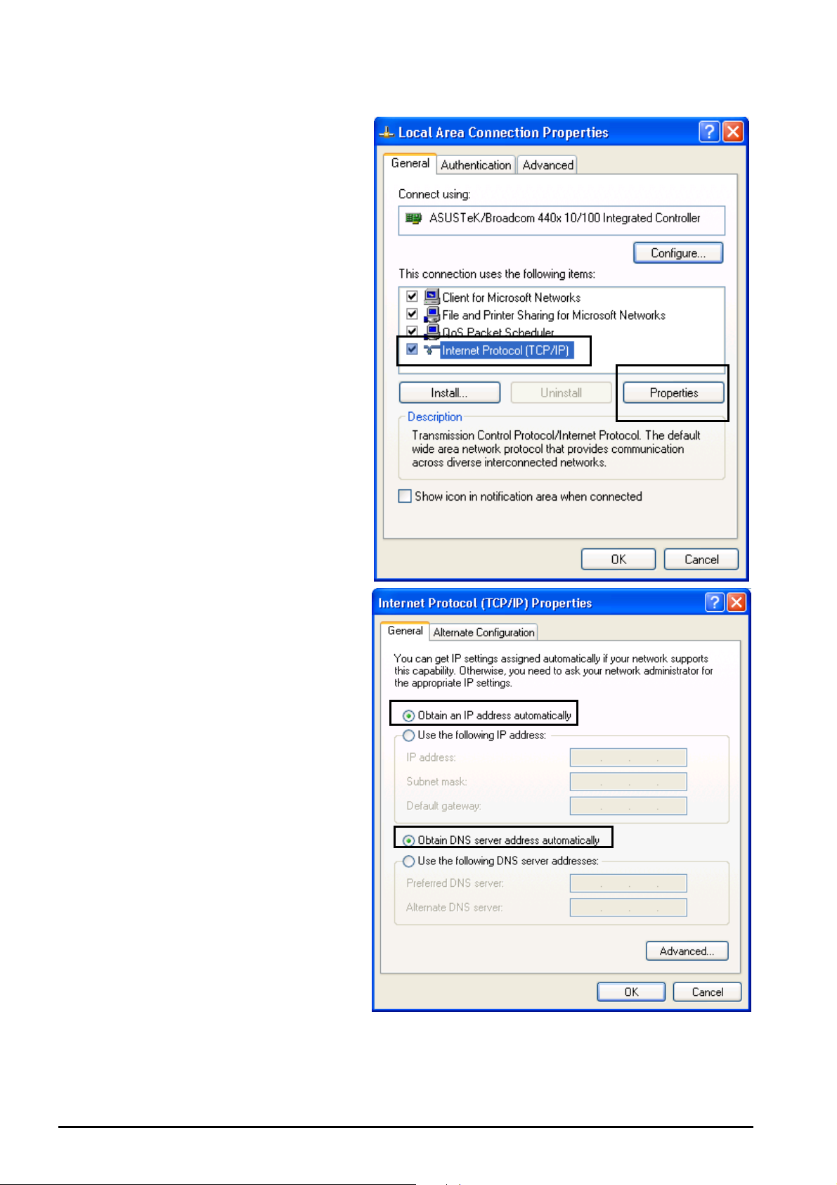
4. Select Internet Protocol
(TCP/IP) and click Properties.
Billion BiPAC 8500/8501/8520/8521 SHDSL (VPN) Firewall Bridge/ Router
5. Select the Obtain an IP
address automatically and the
Obtain DNS server address
automatically radio buttons.
6. Click OK to finish the
configuration.
Chapter 3: Basic Installation
17

For Windows 2000
1. Go to Start / Settings /
Control Panel. In the Control
Panel, double-click on
Network and Dial-up
Connections.
2. Double-click Local Area
Connection.
3. In the Local Area Connection
Status window click
Properties.
Billion BiPAC 8500/8501/8520/8521 SHDSL (VPN) Firewall Bridge/ Router
Chapter 3: Basic Installation
18
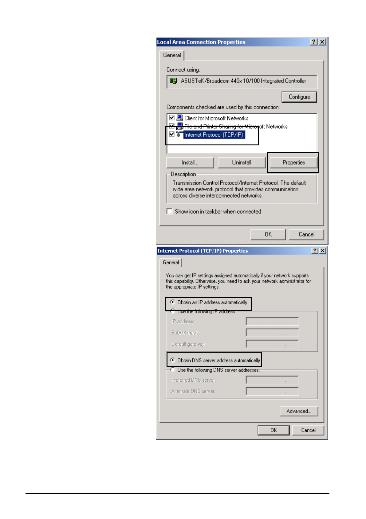
4. Select Internet Protocol
(TCP/IP) and click Properties.
Billion BiPAC 8500/8501/8520/8521 SHDSL (VPN) Firewall Bridge/ Router
5. Select the Obtain an IP
address automatically and
the Obtain DNS server
address automatically radio
buttons.
6. Click OK to finish the
configuration.
19
Chapter 3: Basic Installation
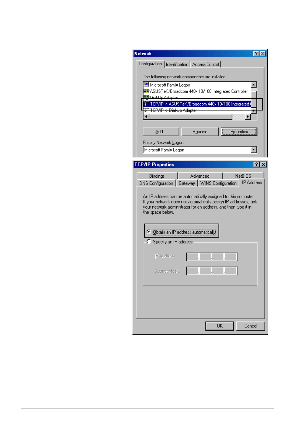
For Windows 98/Me
1. Go to Start / Settings /
Control Panel. In the Control
Panel, double-click on
Network and choose the
Configuration tab.
2. Select TCP/IP ->NE2000
Compatible, or the name of
your Network Interface Card
(NIC) in your PC. Then click
Properties.
3. Select the Obtain an IP
address automatically radio
button.
Billion BiPAC 8500/8501/8520/8521 SHDSL (VPN) Firewall Bridge/ Router
20
Chapter 3: Basic Installation
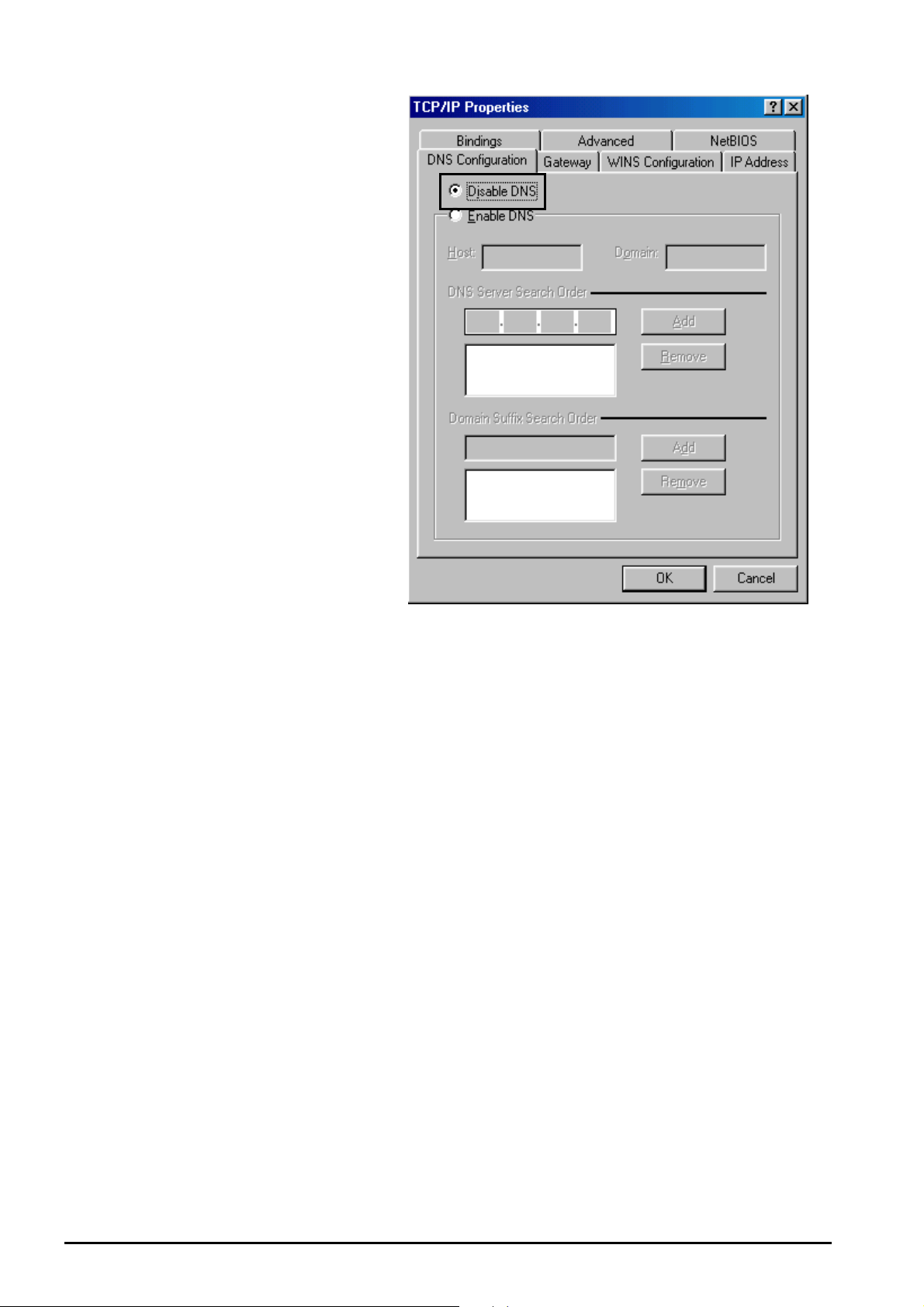
4. Then select the DNS
Configuration tab.
5. Select the Disable DNS radio
button and click OK to finish
the configuration.
Billion BiPAC 8500/8501/8520/8521 SHDSL (VPN) Firewall Bridge/ Router
Chapter 3: Basic Installation
21
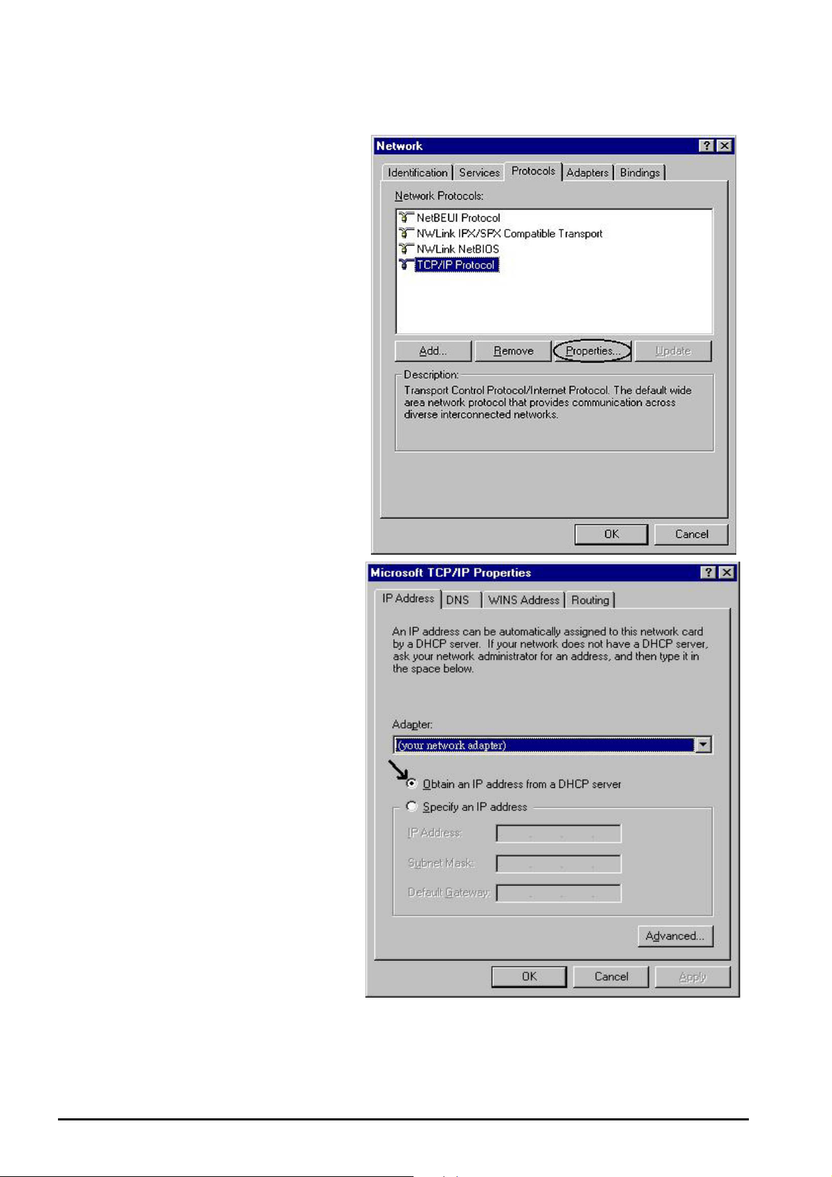
For Windows NT4.0
1. Go to Start / Settings / Control
Panel. In the Control Panel,
double-click on Network and
choose the Protocols tab.
2. Select TCP/IP Protocol and
click Properties.
Billion BiPAC 8500/8501/8520/8521 SHDSL (VPN) Firewall Bridge/ Router
3. Select the Obtain an IP
address from a DHCP server
radio button and click OK.
Chapter 3: Basic Installation
22
Billion BiPAC 8500/8501/8520/8521 SHDSL (VPN) Firewall Bridge/ Router
sure you power
cycle the device again.
Factory Default Settings
Before configuring your router, you need to know the following default settings.
Web Interface (Username and Password):
Username: admin
Password: admin
The default username and password are “admin” and “admin” respectively.
Attention
Attention
If you ever forget the username/password to login to the router, you may
press the RESET button up to 6 seconds to restore the factory default
settings.
Caution: After pressing the RESET button for more than 6 seconds, to be
Device LAN IP Settings:
IP Address: 192.168.1.254
Subnet Mask: 255.255.255.0
ISP setting in WAN site:
PPPoE
DHCP server:
DHCP server is enabled.
Start IP Address: 192.168.1.100
IP pool counts: 100
LAN and WAN Port Addresses
The parameters of LAN and WAN ports are pre-set in the factory. The default values are shown
below.
LAN Port WAN Port
IP address 192.168.1.254
Subnet Mask 255.255.255.0
DHCP server function Enabled
IP addresses for
distribution to PCs
Chapter 3: Basic Installation
The PPPoE function is
enabled to automatically get
the WAN port configuration
from the ISP.
100 IP addresses ranging from
192.168.1.100 to 192.168.1.199
23

Billion BiPAC SHDSL/SHDSL.bis (VPN) Firewall Bridge/ Router
Information from your ISP
Before configuring this device, you have to check with your ISP (Internet Service Provider) to
find out what kind of service is provided such as DHCP (Obtain an IP Address Automatically,
Static IP (Fixed IP Address) and PPPoE.
Gather the information as illustrated in the following table and keep it for reference.
VPI/VCI, VC / LLC-based multiplexing, Username, Password, Service Name,
PPPoE
and Domain Name System (DNS) IP address (it can be automatically
assigned by your ISP when you connect or be set manually).
PPPoE /
PPPoE with
Pass-through
VPI/VCI, VC / LLC-based multiplexing, Username, Password, Service Name,
and Domain Name System (DNS) IP address (it can be automatically
assigned by your ISP when you connect or be set manually). In addition, an
additional WAN address can be assigned using PPPoE dialer.
VPI/VCI, VC / LLC-based multiplexing, Username, Password and Domain
PPPoA
Name System (DNS) IP address (it can be automatically assigned by your
ISP when you connect or be set manually).
RFC 1483
Bridged
VPI/VCI, VC / LLC-based multiplexing to use Bridged Mode.
RFC 1483
Routed
IPoA Routed
(IP over ATM)
VPI/VCI, VC / LLC-based multiplexing, IP address, Subnet mask, Gateway
address, and Domain Name System (DNS) IP address (it is a fixed IP
address).
VPI/VCI, VC / LLC-based multiplexing, IP address, Subnet mask, Gateway
address, and Domain Name System (DNS) IP address (it is a fixed IP
address).
Chapter 3: Basic Installation
24
Billion BiPAC 8500/8501/8520/8521 SHDSL (VPN) Firewall Bridge/ Router
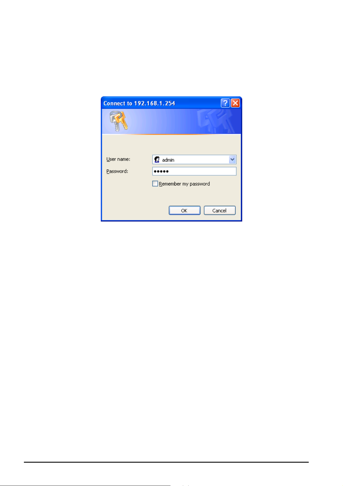
Configuring with your Web Browser
Open your web browser, enter the IP address of your router, which by default is 192.168.1.254,
and click “Go”, a user name and password window prompt will appear. The default username
and password are “admin” and “admin”.
Congratulation! You are now successfully logon to SHDSL Router!
Chapter 3: Basic Installation
25

Billion BiPAC SHDSL/SHDSL.bis (VPN) Firewall Bridge/ Router
Chapter 4: Configuration
At the configuration homepage, the left navigation pane where bookmarks are provided links
you directly to the desired setup page, including:
Status
- ARP Table
- Routing Table
- DHCP Table
- PPTP Status
- IPSec Status
- L2TP Status
- Email Status
- Event Log
- Error Log
- NAT Sessions
- Diagnostic
- UPnP Portmap
Quick Start
Configuration
- LAN
- WAN
- System
- Firewall
- VPN (BiPAC 8500/ 8501/ 8520 Only)
- QoS
- Virtual Server
- Time Schedule
- Advanced
Save Config to FLASH
Language (provides user interface in English and French languages).
Logout
Please click the links to see the relevant sections of this manual for detailed instructions
on how to configure the SHDSL VPN Firewall Bridged Router.
Chapter 4: Configuration
26

Billion BiPAC 8500/8501/8520/8521 SHDSL (VPN) Firewall Bridge/ Router
Status
ARP Table
This section displays the router’s ARP (Address Resolution Protocol) Table, which shows the
mapping of Internet (IP) addresses to Ethernet (MAC) addresses. This is a useful & quick way
to determine the MAC address of your PCs network interface through the router’s Firewall –
MAC Address Filter function. See the Firewall section of this manual for more information on
this feature.
IP Address: A list of IP addresses of devices on your LAN (Local Area Network).
MAC Address: The MAC (Media Access Control) addresses for each device on your LAN.
Interface: The interface name (on the router) that this IP Address connects to.
Static: Static status of the ARP table entry:
“no” for dynamically-generated ARP table entries
“yes” for static ARP table entries added by the user
Chapter 4: Configuration
27

Billion BiPAC SHDSL/SHDSL.bis (VPN) Firewall Bridge/ Router
Routing Table
Routing Table
Valid: It indicates a successful routing status.
Destination: The IP address of the destination network.
Netmask: The destination netmask address.
Gateway/Interface: The IP address of the gateway or existing interface that this route will
use.
Cost: The number of hops counted as the cost of the route.
RIP Routing Table
Destination: The IP address of the destination network.
Netmask: The destination netmask address.
Gateway: The IP address of the gateway that this route will use.
Cost: The number of hops counted as the cost of the route.
Chapter 4: Configuration
28

Billion BiPAC SHDSL/SHDSL.bis (VPN) Firewall Bridge/ Router
DHCP Table
Leased: The DHCP assigned IP addresses information.
IP Address: A list of IP addresses of devices on your LAN (Local Area Network).
Expired: The expired IP addresses information.
Permanent: The fixed host mapping information
Leased Table
IP Address: The IP address that assigned to client.
MAC Address: The MAC address of client.
Client Host Name: The Host Name (Computer Name) of client.
Expiry: The current lease time of client.
Expired Table
Please refer the Leased Table.
Permanent Table
Name: The name you assigned to the Permanent configuration.
IP Address: The fixed IP address for the specify client.
MAC Address: The MAC Address that you want to assign the fixed IP address
Maximum Lease Time: The maximum lease time interval you allow to clients
29
Chapter 4: Configuration

Billion BiPAC 8500/8501/8520/8521 SHDSL (VPN) Firewall Bridge/ Router
PPTP Status (BiPAC 8500/ 8501/ 8520 Only)
This shows details of your configured PPTP VPN Connections.
• Name: The name you assigned to the particular PPTP connection in your VPN
configuration.
• Type: The type of connection (dial-in/dial-out).
• Enable: Whether the connection is currently enabled.
• Active: Whether the connection is currently active.
• Tunnel Connected: Whether the VPN Tunnel is currently connected.
• Call Connected: If the Call for this VPN entry is currently connected.
• Encryption: The encryption type used for this VPN connection.
Chapter 4: Configuration
30
Billion BiPAC 8500/8501/8520/8521 SHDSL (VPN) Firewall Bridge/ Router
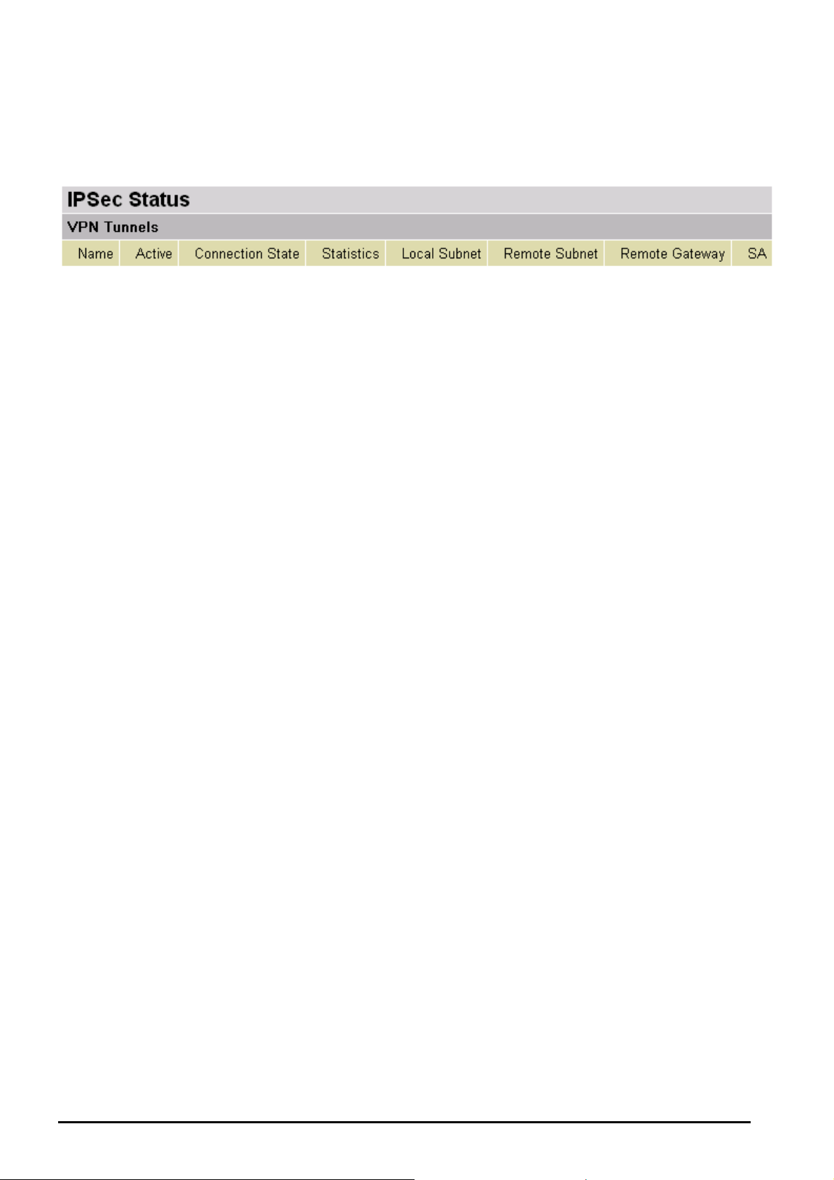
IPSec Status (BiPAC 8500/ 8501/ 8520 Only)
This shows details of your configured IPSec VPN Connections.
• Name: The name you assigned to the particular VPN entry.
• Active: Whether the VPN Connection is currently Active.
• Connection State: Whether the VPN is Connected or Disconnected.
• Statistics: Statistics for this VPN Connection.
• Local Subnet: The local IP Address or Subnet used.
• Remote Subnet: The Subnet of the remote site.
• Remote Gateway: The Remote Gateway IP address.
• SA: The Security Association for this VPN entry.
Chapter 4: Configuration
31
Billion BiPAC 8500/8501/8520/8521 SHDSL (VPN) Firewall Bridge/ Router
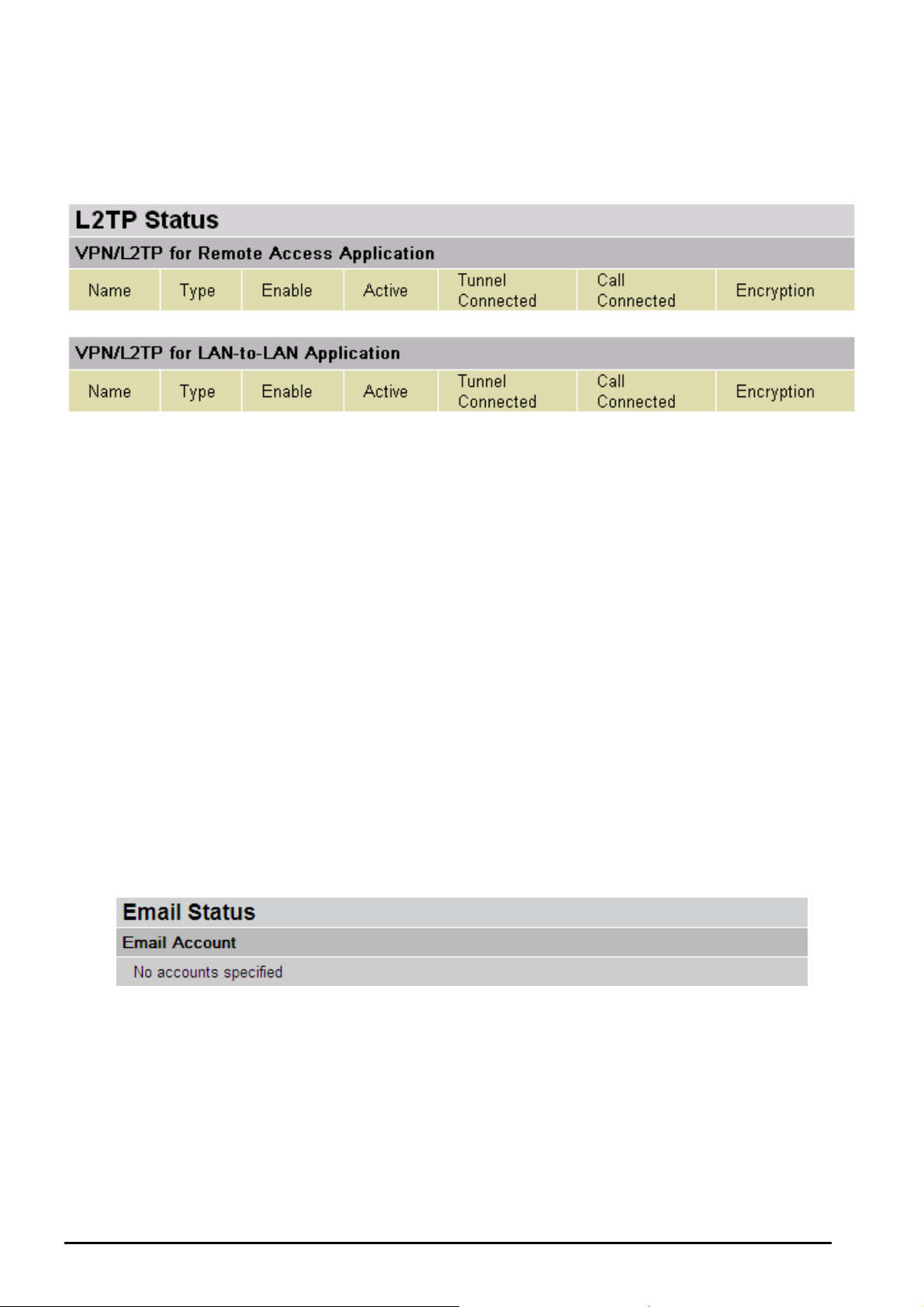
L2TP Status (BiPAC 8500/ 8501/ 8520 Only)
This shows details of your configured L2TP VPN Connections.
• Name: The name you assigned to the particular L2TP connection in your VPN
configuration.
• Type: The type of connection (dial-in/dial-out).
• Enable: Whether the connection is currently enabled.
• Active: Whether the connection is currently active.
• Tunnel Connected: Whether the VPN Tunnel is currently connected.
• Call Connected: If the Call for this VPN entry is currently connected.
• Encryption: The encryption type used for this VPN connection.
Email Status
Details and status for the Email Account you have configured the router to check. Please see
the Advanced section of this manual for details on this function.
Chapter 4: Configuration
32

Billion BiPAC SHDSL/SHDSL.bis (VPN) Firewall Bridge/ Router
Event Log
This page displays the router’s Event Log entries. Major events are logged to this window, such
as when the router’s ADSL connection is disconnected, and Firewall events such as when you
have enabled Intrusion or Blocking Logging in the Configuration – Firewall section of the
interface. Please see the Firewall section of this manual for more details on how to enable
Firewall logging.
Error Log
Any errors encountered by the router (e.g. invalid names given to entries) are logged to this
window.
Chapter 4: Configuration
33
Billion BiPAC SHDSL/SHDSL.bis (VPN) Firewall Bridge/ Router
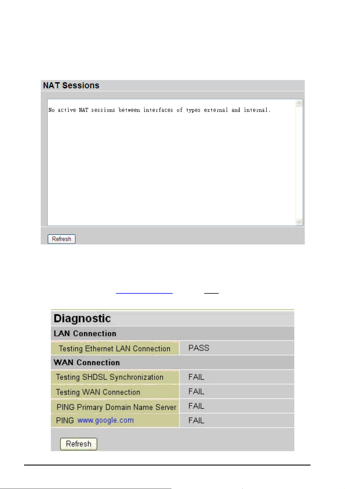
NAT Sessions
This section lists all current NAT sessions between interface of types external (WAN) and
internal (LAN).
Diagnostic
It tests the connection of computer(s) which is connected to LAN ports and also the WAN
Internet connection. If PING www.google.com is shown FAIL and the rest is PASS, you ought
to check if your PC’s DNS setting is correct.
Chapter 4: Configuration
34

Billion BiPAC 8500/8501/8520/8521 SHDSL (VPN) Firewall Bridge/ Router
UPnP Portmap
The section lists all port-mapping established using UPnP (Universal Plug and Play). Please
see the Advanced section of this manual for more details on UPnP and the router’s UPnP
configuration options.
Chapter 4: Configuration
35
Billion BiPAC SHDSL/SHDSL.bis (VPN) Firewall Bridge/ Router
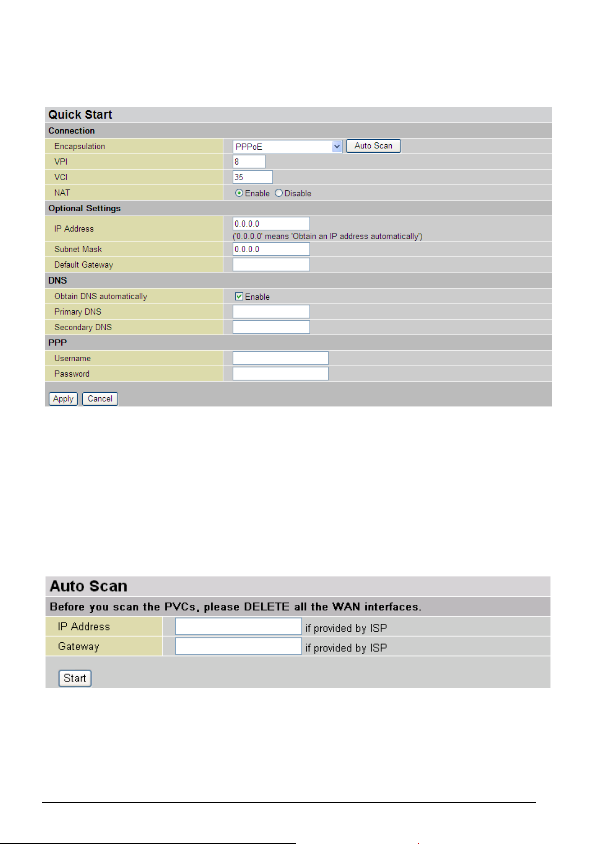
Quick Start
For detailed instructions on configuring your WAN settings, please see the WAN section of this
manual.
Usually, the only details you will need for the Quick Start wizard to get you online are your login
(often in the form of username@ispname), your password and the encapsulation type. In
addition to this, you can either provide a specific DNS, or check the Enable box to get the DNS
automatically from your ISP.
Your ISP will be able to supply all the details you need, alternatively, if you have deleted the
current WAN Connection in the WAN – ISP section of the interface, you can use the router’s
PVC Scan feature to attempt to determine the Encapsulation types offered by your ISP.
Click Start to begin scanning for encapsulation types offered by your ISP. If the scan is
successful you will then be presented with a list of supported options:
Chapter 4: Configuration
36

Billion BiPAC 8500/8501/8520/8521 SHDSL (VPN) Firewall Bridge/ Router
Select the desired option from the list and click Apply to return to the Quick Start interface to
continue configuring your ISP connection. Please note that the contents of this list will vary,
depending on what is supported by your ISP.
Chapter 4: Configuration
37

Billion BiPAC 8500/8501/8520/8521 SHDSL (VPN) Firewall Bridge/ Router
Configuration
When you click this item, you will get the following sub-items to configure your router:
LAN, WAN, System, Firewall, VPN (not available in 8521), QoS, Virtual Server, Time
Schedule and Advanced
These functions are described below in the following sections.
LAN (Local Area Network)
There are seven items within the LAN section: Bridge Interface, Ethernet, IP Alias, Ethernet
Client Filter, Port Setting and DHCP Server.
Bridge Interface
You can setup member ports for each VLAN group under Bridge Interface section. From the
example, two VLAN groups need to be created.
Ethernet: P1 (Port 1)
Ethernet1: P2, P3 and P4 (Port 2, 3, 4) Please uncheck P2, P3, P4 from Ethernet VLAN port
first.
Note: You should setup each VLAN group with caution. Each Bridge Interface is arranged in
this order.
Bridge Interface VLAN Port (Always starts
with)
Ethernet P1 / P2 / P3 / P4
Ethernet1 P2 / P3 / P4
Ethernet2 P3 / P4
Ethernet3 P4
Chapter 4: Configuration
38

Billion BiPAC SHDSL/SHDSL.bis (VPN) Firewall Bridge/ Router
Edit Ethernet Interface Parameter
Click on a specific Ethernet you that you wish to edit its interface parameter under the Bridged
Interface section.
You can also edit the Ethernet Interface parameter such as its Acceptable Frame Type; Filter
Type or PVID for Untagged Frames. When the editing is complete, click Apply to save the
changes and then click Return to go back to the Bridged Interface page.
Management Interface: To specify which VLAN group is responsible for device management,
like doing web management.
Note: NAT/NAPT can be applied to management interface only.
Ethernet
Primary IP Address
• IP Address: The default IP of this router.
• SubNetmask: The default subnet mask of this router.
• RIP: RIP v1, RIP v2, and RIP v2 Multicast. Check to enable RIP function.
Chapter 4: Configuration
39

Billion BiPAC 8500/8501/8520/8521 SHDSL (VPN) Firewall Bridge/ Router
IP Alias
This function supports the creation of multiple virtual IP interfaces on this router. It helps to
connect two or more local networks to the ISP or a remote node. In this case, an internal router
is not required.
Click Add to add a new IP alias.
• IP Address: Specify an IP address on this virtual interface.
• SubNetmask: Specify a subnet mask on this virtual interface.
• Security Interface: Specify the firewall setting on this virtual interface.
• Internal: The network is behind NAT. All traffic will translate network address when being
sent out to the Internet if NAT is enabled.
• External: There is no NAT on this IP interface and it is connecting to the Internet directly.
This is used when provided with multiple public IP addresses by ISP. In this case, you
can use the public IP address in the local network with gateway IP address point to the
IP address on this interface.
• DMZ: Specify this network to the DMZ area. There is no NAT on this interface
.
Chapter 4: Configuration
40

Billion BiPAC SHDSL/SHDSL.bis (VPN) Firewall Bridge/ Router
Ethernet Client Filter
The Ethernet Client Filter supports up to 16 Ethernet network machines that helps you to
manage your network control to accept traffic from specific authorized machines or to restrict
unwanted machine(s) to access your LAN.
There are no pre-define Ethernet MAC address filter rules; you can add the filter rules to meet
your requirements.
Ethernet Client Filter: Default setting is set to Disable.
• Allowed: check to authorize specific device accessing your LAN by inserting the MAC
Address in the space provided or click . Make sure your PC’s MAC is listed.
• Blocked: check to prevent unwanted device from accessing your LAN by inserting the
MAC Address in the space provided or click . Make sure your PC’s MAC is
not listed.
The maximum number of client is 16. The MAC address is 6 byte long; it is presented only in
hexadecimal characters. The number 0 - 9 and letters a - f are acceptable.
Note: Follow the MAC Address Format xx:xx:xx:xx:xx:xx. Semicolon ( : ) must be included
Candidates: automatically detects devices connected to the router through the Ethernet. .
→ Active PC in LAN
Chapter 4: Configuration
41

Billion BiPAC 8500/8501/8520/8521 SHDSL (VPN) Firewall Bridge/ Router
Active PC in LAN displays a list of IP Address & MAC Address of each individual Ethernet
device which is connected to the router.
You can check the box next to the IP address to block or allow. Then, click Add to insert to the
Ethernet Client Filter table. The maximum number of Ethernet client is 16.
42
Chapter 4: Configuration

Billion BiPAC SHDSL/SHDSL.bis (VPN) Firewall Bridge/ Router
Port Setting
This section allows you to configure the settings for the router’s Ethernet ports to solve some of
the compatibility problems that may be encountered while connecting to the Internet, as well
allowing users to tweak the performance of their network.
• Port # Connection Type: Six options to choose from: Auto, 10M half-duplex, 10M full-
duplex, 100M half-duplex, 100M full-duplex and Disable. Sometimes, there are Ethernet
compatibility problems with legacy Ethernet devices, and you can configure different
types to solve compatibility issues. The default is Auto, which users should keep unless
there are specific problems with PCs not being able to access your LAN.
nd
• IPv4 TOS priority Control (Advanced users): TOS, Type of Services, is the 2
an IP packet. Bits 6-7 of this octet are reserved and bit 0-5 are used to specify the priority
of the packet.
This feature uses bits 0-5 to classify the packet’s priority. If the packet is high priority, it
will flow first and will not be constrained by the Rate Limit. Therefore, when this feature is
enabled, the router’s Ethernet switch will check the 2
nd
octet of each IP packet. If the
value in the TOS field matches the checked values in the table (0 to 63), this packet will
be treated as high priority.
octet of
Chapter 4: Configuration
43

Billion BiPAC 8500/8501/8520/8521 SHDSL (VPN) Firewall Bridge/ Router
DHCP Server
You can disable or enable the DHCP (Dynamic Host Configuration Protocol) server or enable
the router’s DHCP relay functions. The DHCP protocol allows your router to dynamically assign
IP addresses to PCs on your network if they are configured to obtain IP addresses automatically.
To disable the router’s DHCP Server, check Disabled and click Next, then click Apply. When
the DHCP Server is disabled you will need to manually assign a fixed IP address to each PCs
on your network, and set the default gateway for each PCs to the IP address of the router (by
default this is 192.168.1.254).
To configure the router’s DHCP Server, check DHCP Server and click Next. You can then
configure parameters of the DHCP Server including the IP pool (starting IP address and ending
IP address to be allocated to PCs on your network), lease time for each assigned IP address
(the period of time the IP address assigned will be valid), DNS IP address and the gateway IP
address. These details are sent to the DHCP client (i.e. your PC) when it requests an IP
address from the DHCP server. Click Apply to enable this function. If you check “Use Router
as a DNS Server”, the Router will perform the domain name lookup, find the IP address from
the network outside your network automatically and forward it back to the requesting PC in the
LAN (your Local Area Network).
44
Chapter 4: Configuration

Billion BiPAC 8500/8501/8520/8521 SHDSL (VPN) Firewall Bridge/ Router
If you check DHCP Relay Agent and click Next, then you will have to enter the IP address of
the DHCP server which will assign an IP address back to the DHCP client in the LAN. Use this
function only if advised to do so by your network administrator or ISP.
Click Apply to enable this function.
Chapter 4: Configuration
45

Billion BiPAC SHDSL/SHDSL.bis (VPN) Firewall Bridge/ Router
WAN (Wide Area Network)
WAN refers to your Wide Area Network connection, i.e. your router’s connection to your ISP and
the Internet. There are three items within the WAN section: ISP, DNS and SHDSL.
ISP
The factory default is PPPoE. If your ISP uses this access protocol, click Edit to input other
parameters as below. If your ISP does not use PPPoE, you can change the default WAN
connection entry by clicking Change.
Some ISP may provide more service via different WAN connection. In this case, you can create
more connections by clicking Create to enter the configuration page to setup the type of sevice
from the list then press Next to continue with the configuration. There are 5 types of ISP service
to choose from: RFC 1483 Routed, PPPoA Routed, PPPoE Routed, RFC 1483 Bridged and
IPoA Routed. The device can support maximum of up to 8 WAN connections.
Note: The application of multiple WAN connections depends on your Internet Service Provider.
A simpler alternative is to select Quick Start from the main menu on the left wondow pane.
Please see the Quick Start section of the manual for more information.
Chapter 4: Configuration
46

Billion BiPAC SHDSL/SHDSL.bis (VPN) Firewall Bridge/ Router
RFC 1483 Routed Connections
• Description: User-definable name for the connection.
• VPI and VCI: Enter the information provided by your ISP.
• ATM Class: The Quality of Service for ATM layer.
• NAT: The NAT (Network Address Translation) feature allows multiple users to access the
Internet through a single IP account by sharing the single IP address. If users on your
LAN have their own public IP addresses for accessing Internet directly, the NAT function
can be disabled.
• Encapsulation method: Select the encapsulation format, the default is LLC Bridged.
Select the one provided by your ISP.
• IP Assignment
o Obtain an IP address automatically via DHCP client: specify if the Router can
get an IP address from the ISP (Internet Service Provider) automatically.
o Use the following IP Address: Specify the IP address manually; the IP should be
Chapter 4: Configuration
47

Billion BiPAC 8500/8501/8520/8521 SHDSL (VPN) Firewall Bridge/ Router
given by you our ISP.
• RIP: RIP v1, RIP v2, and RIP v2 Multicast. Check to enable RIP function.
• MTU: Maximum Transmission Unit. The size of the largest datagram (excluding media-
specific headers) that IP will attempt to send through the interface.
• TCP MSS Clamp: This option helps to auto detect the optimal MTU size. Default is
enabled.
• MAC Address Spoofing: This option is required by Service Providers. You must fill in
the MAC address that is specified by your Service Provider if this is required. Default is
disabled.
Chapter 4: Configuration
48

Billion BiPAC 8500/8501/8520/8521 SHDSL (VPN) Firewall Bridge/ Router
RFC 1483 Bridged Connections
• Description: User-definable name for the connection.
• VPI and VCI: Enter the information provided by your ISP.
• ATM Class: The Quality of Service for ATM layer.
• Encapsulation method: Select the encapsulation format, this is provided by your ISP.
• Acceptable Frame Type: Specify what kind of traffic can pass through this connection,
all traffic or only VLAN tagged.
• Filter Type: Specify the type of ethernet filtering performed by the named bridge
interface.
All Allows all types of ethernet packets through the port.
Ip Allows only IP/ARP types of ethernet packets through the port.
Pppoe Allows only PPPoE types of ethernet packets through the port.
• PVID for Untagged Frames: PVID is known as Port VLAN Identifier. When an untagged
packet is received by input port(s), this packet will be tagged with a specific PVID. The
valid value range for PVID is 1~4094.
Chapter 4: Configuration
49
Billion BiPAC SHDSL/SHDSL.bis (VPN) Firewall Bridge/ Router
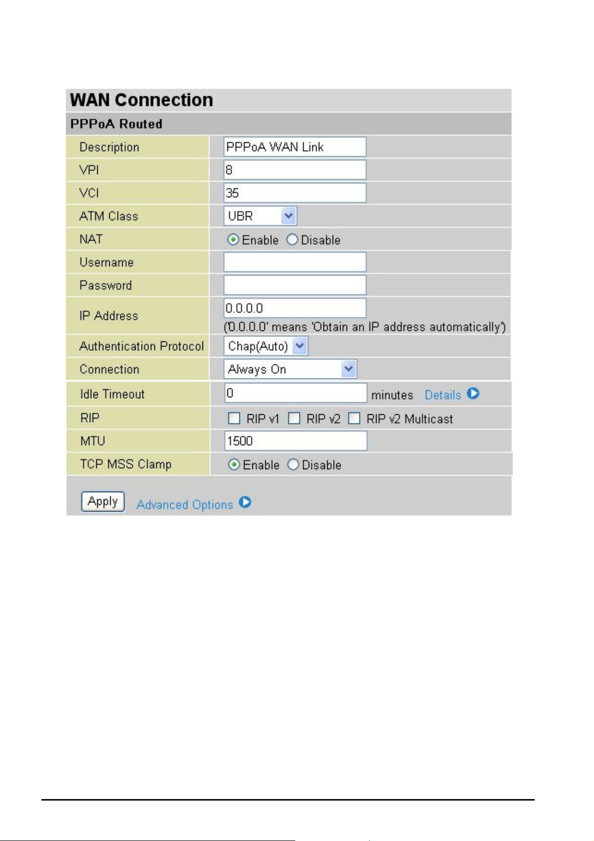
PPPoA Routed Connections
• Description: User-definable name for the connection.
• VPI/VCI: Enter the information provided by your ISP.
• ATM Class: The Quality of Service for ATM layer.
• NAT: The NAT (Network Address Translation) feature allows multiple users to access the
Internet through a single IP account by sharing a single IP address. If users on your LAN
have their own public IP addresses for accessing Internet directly, the NAT function can
be disabled.
• Username: Enter the username provided by your ISP. You can input up to 128
alphanumeric characters (case sensitive). This will usually be in the format of
“username@ispname” instead of simply “username”.
• Password: Enter the password provided by your ISP. You can input up to 128
alphanumeric characters (case sensitive).
• IP Address: specify if the Router can get an IP address from the Internet Server
Chapter 4: Configuration
50

Billion BiPAC 8500/8501/8520/8521 SHDSL (VPN) Firewall Bridge/ Router
Provider (ISP) automatically or not. Please click Obtain an IP address automatically via
DHCP client to enable the DHCP client function or click Specify an IP address to disable
the DHCP client function, and specify the IP address manually. The setting of this item is
specified by your ISP.
• Authentication Protocol Type: Default is Chap (Auto). Your ISP will advise you
whether to use Chap or Pap.
• Connection:
o Always on: If you want the router to establish a PPPoA session when starting up
and to automatically re-establish the PPPoA session when disconnected by the
ISP.
o Connect to Demand: If you want to establish a PPPoA session only when there
is a packet requesting to access the Internet (i.e. when a program on your
computer attempts to access the Internet).
• Idle Timeout: Auto-disconnect the broadband firewall gateway when there is no activity
on the line for a predetermined period of time.
o Detail: You can define the destination port and packet type (TCP/UDP) without
being checked by the timer. It allows you to set which outgoing traffic will not
trigger and reset the idle timer.
• RIP: RIP v1, RIP v2, and RIP v2 Multicast. Check to enable RIP function.
• MTU: Maximum Transmission Unit. The size of the largest datagram (excluding media-
specific headers) that IP will attempt to send through the interface.
• TCP MSS Clamp: This option helps to auto detect the optimal MTU size. Default is
enabled.
Chapter 4: Configuration
51

Billion BiPAC 8500/8501/8520/8521 SHDSL (VPN) Firewall Bridge/ Router
Advanced Options (PPPoA)
• LLC Header: Select encapsulation mode, true for using LLC or false for using VC-Mux.
• Create Route: This setting specifies whether a route is to be added to the system after
IPCP (Internet Protocol Control Protocol) negotiation is complete. If set to enabled, a
route will be created which directs packets to the remote end of the PPP link.
• Specific Route: Specify whether the route created when a PPP link comes up is a
specific or default route. If set to enabled, the route created will only be applied to
packets for the subnet at the remote end of the PPP link. The address of this subnet is
obtained during IPCP negotiation.
• Subnet Mask: Set the subnet mask used for the local IP interface connected to the PPP
transport. If the value 0.0.0.0 is supplied, the netmask will be calculated from the class of
the IP address obtained during IPCP negotiation.
• Route Mask: Set the subnet mask used by the route that is created when a PPP link
comes up. If it is set to 0.0.0.0, the subnet mask is determined by the IP address of the
remote end of the link. The class of the IP address is obtained during IPCP (Internet
Protocol Control Protocol) negotiation.
• MRU: Maximum Receive Unit. This is negotiated during the LCP protocol stage.
Chapter 4: Configuration
52

IPoA Routed Connections
Billion BiPAC 8500/8501/8520/8521 SHDSL (VPN) Firewall Bridge/ Router
• Description: User-definable name for the connection.
• VPI/VCI: Enter the information provided by your ISP.
• ATM Class: The Quality of Service for ATM layer.
• NAT: The NAT (Network Address Translation) feature allows multiple users to access the
Internet through a single IP account by sharing a single IP address. If users on your LAN
have their own public IP addresses for accessing Internet directly, the NAT function can
be disabled.
• IP Assignment
o Obtain an IP address automatically via DHCP client: specify if the Router can
get an IP address from the ISP (Internet Service Provider) automatically.
o Use the following IP Address: Specify the IP address manually; the IP should be
given by you our ISP.
Chapter 4: Configuration
53

Billion BiPAC 8500/8501/8520/8521 SHDSL (VPN) Firewall Bridge/ Router
• RIP: RIP v1, RIP v2, and RIP v2 Multicast. Check to enable RIP function.
• MTU: Maximum Transmission Unit. The size of the largest datagram (excluding media-
specific headers) that IP will attempt to send through the interface.
• TCP MSS Clamp: This option helps to auto detect the optimal MTU size. Default is
enabled.
Chapter 4: Configuration
54

PPPoE Connections
Billion BiPAC 8500/8501/8520/8521 SHDSL (VPN) Firewall Bridge/ Router
• Description: User-definable name for this connection.
• VPI/VCI: Enter the information provided by your ISP.
• ATM Class: The Quality of Service for ATM layer.
• NAT: The NAT (Network Address Translation) feature allows multiple users to access the
Internet through a single IP account by sharing a single IP address. If users on your LAN
have their own public IP addresses for accessing Internet directly, the NAT function can
be disabled.
• Username: Enter the username provided by your ISP. You can input up to 128
55
Chapter 4: Configuration

Billion BiPAC 8500/8501/8520/8521 SHDSL (VPN) Firewall Bridge/ Router
alphanumeric characters (case sensitive). This will usually be in the format of
“username@ispname” instead of simply “username”.
• Password: Enter the password provided by your ISP. You can input up to 128
alphanumeric characters (case sensitive).
• Service Name: This item is for identification purposes. If it is required, your ISP will
provide you the information. Maximum input is 20 alphanumeric characters.
• IP Address: specify if the Router can get an IP address from the Internet Server
Provider (ISP) automatically or not. Please click Obtain an IP address automatically via
DHCP client to enable the DHCP client function or click Specify an IP address to disable
the DHCP client function, and specify the IP address manually. The setting of this item is
specified by your ISP.
• Authentication Protocol: Default is Chap (Auto). Your ISP will advise you whether to
use Chap or Pap.
• Connection
o Always on: If you want the router to establish a PPPoE session when starting up
and to automatically re-establish the PPPoE session when disconnected by the
ISP.
o Connect on Demand: If you want to establish a PPPoE session only when there
is a packet requesting access to the Internet (i.e. when a program on your
computer attempts to access the Internet).
• Idle Timeout: Auto-disconnect the broadband firewall gateway when there is no activity
on the line for a predetermined period of time.
o Detail: You can define the destination port and packet type (TCP/UDP) without
being checked by the timer. It allows you to set which outgoing traffic will not
trigger and reset the idle timer.
• RIP: RIP v1, RIP v2, and RIP v2 Multicast. Check to enable RIP function.
• MTU: Maximum Transmission Unit. The size of the largest datagram (excluding media-
specific headers) that IP will attempt to send through the interface.
• TCP MSS Clamp: This option helps to auto detect the optimal MTU size. Default is
enabled.
• MAC Address Spoofing: This option is required by Service Providers. You must fill in
the MAC address that is specified by your Service Provider if this is required. Default is
disabled.
56
Chapter 4: Configuration

Billion BiPAC 8500/8501/8520/8521 SHDSL (VPN) Firewall Bridge/ Router
Advanced Options (PPPoE)
• LLC Header: Selects encapsulation mode, true for using LLC or false for using VC-Mux.
• Create Route: This setting specify whether a route is to be added to the system after
IPCP (Internet Protocol Control Protocol) negotiation is completed. If set to enabled, a
route will be created which directs packets to the remote end of the PPP link.
• Specific Route: Specify whether the route created when a PPP link comes up is a
specific or default route. If set to enabled, the route created will only apply to packets for
the subnet at the remote end of the PPP link. The address of this subnet is obtained
during IPCP negotiation.
• Subnet Mask: set the subnet mask used for the local IP interface connected to the PPP
transport. If the value 0.0.0.0 is supplied, the netmask will be calculated from the class of
the IP address obtained during IPCP negotiation.
• Route Mask: Set the subnet mask used by the route that is created when a PPP link
comes up. If it is set to 0.0.0.0, the subnet mask is determined by the IP address of the
remote end of the link. The class of the IP address is obtained during IPCP (Internet
Protocol Control Protocol) negotiation.
• MRU: Maximum Receive Unit. This is negotiated during the LCP protocol stage.
Chapter 4: Configuration
57

Billion BiPAC 8500/8501/8520/8521 SHDSL (VPN) Firewall Bridge/ Router
PPPoE with Pass-through Connections
To access PPPoE with Pass-through Connection: Press Change > PPPoE Routed with PassThrough > Quick Start
PPPoE with pass-through adapts the following method: PPPoE Routed mode + 1483 Bridge
Mode. With pure PPPoE connection, the router can get one WAN address to the router. With
the PPPoE and PPPoE pass-through, concurrently, it allows user to have a WAN address
assigned to the router but also able to get another WAN IP from ISP using PPPoE dialer (e.g
WinPoETor Windows XP PPPoE Dialer) at the same time.
Chapter 4: Configuration
58

Billion BiPAC 8500/8501/8520/8521 SHDSL (VPN) Firewall Bridge/ Router
• Description: User-definable name for this connection.
• VPI/VCI: Enter the information provided by your ISP.
• ATM Class: The Quality of Service for ATM layer.
• NAT: The NAT (Network Address Translation) feature allows multiple users to access the
Internet through a single IP account by sharing a single IP address. If users on your LAN
have their own public IP addresses for accessing Internet directly, the NAT function can
be disabled.
• Username: Enter the username provided by your ISP. You can input up to 128
alphanumeric characters (case sensitive). This will usually be in the format of
“username@ispname” instead of simply “username”.
• Password: Enter the password provided by your ISP. You can input up to 128
alphanumeric characters (case sensitive).
Chapter 4: Configuration
59

Billion BiPAC 8500/8501/8520/8521 SHDSL (VPN) Firewall Bridge/ Router
• Service Name: This item is for identification purposes. If it is required, your ISP will
provide you the information. Maximum input is 20 alphanumeric characters.
• IP Address: specify if the Router can get an IP address from the Internet Server
Provider (ISP) automatically or not. Please click Obtain an IP address automatically via
DHCP client to enable the DHCP client function or click Specify an IP address to disable
the DHCP client function, and specify the IP address manually. The setting of this item is
specified by your ISP.
• Authentication Protocol: Default is Chap (Auto). Your ISP will advise you whether to
use Chap or Pap.
• Connection:
o Always on: If you want the router to establish a PPPoE session when starting up
and to automatically re-establish the PPPoE session when disconnected by the
ISP.
o Connect on Demand: If you want to establish a PPPoE session only when there
is a packet requesting access to the Internet (i.e. when a program on your
computer attempts to access the Internet).
• Idle Timeout: Auto-disconnect the broadband firewall gateway when there is no activity
on the line for a predetermined period of time.
o Detail: You can define the destination port and packet type (TCP/UDP) without
being checked by the timer. It allows you to set which outgoing traffic will not
trigger and reset the idle timer.
• RIP: RIP v1, RIP v2, and RIP v2 Multicast. Check to enable RIP function.
• MTU: Maximum Transmission Unit. The size of the largest datagram (excluding media-
specific headers) that IP will attempt to send through the interface.
• TCP MSS Clamp: This option helps to auto detect the optimal MTU size. Default is
enabled.
Chapter 4: Configuration
60

Billion BiPAC 8500/8501/8520/8521 SHDSL (VPN) Firewall Bridge/ Router
Advanced Options (PPPoE)
LLC Header: Select encapsulation mode, true for using LLC or false for using VC-Mux.
Create Route: This setting specifies whether a route is to be added to the system after IPCP
(Internet Protocol Control Protocol) negotiation is complete. If set to enabled, a route will be
created which directs packets to the remote end of the PPP link.
Specific Route: Specify whether the route created when a PPP link comes up is a specific or
default route. If set to enabled, the route created will only apply to packets for the subnet at the
remote end of the PPP link. The address of this subnet is obtained during IPCP negotiation.
Subnet Mask: set the subnet mask used for the local IP interface connected to the PPP
transport. If the value 0.0.0.0 is supplied, the netmask will be calculated from the class of the IP
address obtained during IPCP negotiation.
Route Mask: Set the subnet mask used by the route that is created when a PPP link comes up.
If it is set to 0.0.0.0, the subnet mask is determined by the IP address of the remote end of the
link. The class of the IP address is obtained during IPCP (Internet Protocol Control Protocol)
negotiation.
MRU: Maximum Receive Unit. This is negotiated during the LCP protocol stage.
Discover Primary / Secondary DNS: This setting enables/disables whether the
primary/secondary DNS server address is requested from a remote PPP peer using IPCP. The
default setting for this command is enabled.
Give DNS to Relay: Control whether the PPP Internet Protocol Control Protocol (IPCP) can
request the DNS server IP address for a remote PPP peer. Once IPCP has discovered the DNS
server IP address, it automatically gives the address to the local DNS relay so that a connection
can be established.
Give DNS to Client: Control whether the PPP Internet Protocol Control Protocol (IPCP) can
request a DNS server IP address for a remote PPP peer. Once IPCP has discovered the DNS
server IP address, it automatically gives the address to the local DNS client so that a
connection can be established.
Give DNS to DHCP Server: Similar to the above, but it gives the DNS server address to the
DHCP server instead.
61
Chapter 4: Configuration

Billion BiPAC 8500/8501/8520/8521 SHDSL (VPN) Firewall Bridge/ Router
Discover Primary NBNS / Discover Secondary NBNS: This setting enables/disables whether
the primary/secondary NBNS server address is requested from a remote PPP peer using IPCP.
The default setting for this command is disabled.
Discover Subnet Mask: Specify if the subnet mask given by IPCP negotiation process is to be
used.
Give Subnet Mask To DHCP Server: Enable to change your DHCP Server settings by using
the given information in IPCP negotiation process.
Chapter 4: Configuration
62

Billion BiPAC 8500/8501/8520/8521 SHDSL (VPN) Firewall Bridge/ Router
DNS
A Domain Name System (DNS) contains a mapping table for domain name and IP addresses.
On the Internet, every host has a unique and user-friendly name (domain name) such as
www.helloworld.com and an IP address. An IP address is a 32-bit number in the form of
xxx.xxx.xxx.xxx, for example 192.168.1.254. You can think of an IP address as a telephone
number for devices on the Internet, and the DNS will allow you to find the telephone number for
any particular domain name. As an IP Address is hard to remember, the DNS converts the
friendly name into its equivalent IP Address.
You can obtain a Domain Name System (DNS) IP address automatically if your ISP has
provided it when you logon, check the Enable box. Usually when you choose PPPoE or PPPoA
as your WAN - ISP protocol, the ISP will provide the DNS IP address automatically. You may
leave the configuration field blank.
Alternatively, your ISP may provide you with an IP address of their DNS. If this is the case, you
must enter the DNS IP address manually.
If you choose one of the other three protocols ─ RFC1483 Routed/Bridged and IPoA, check
with your ISP as it may provide you with an IP address for their DNS server. You must enter the
DNS IP address if you set the DNS of your PC to the LAN IP address of this router.
Chapter 4: Configuration
63

SHDSL-BiPAC 8500
Billion BiPAC 8500/8501/8520/8521 SHDSL (VPN) Firewall Bridge/ Router
• Mode: The SHDSL device can function as a CPE (Customer Premises Equipment) or
CO (Central Office). Select CPE mode when the BiPAC 8500 is connected to your ISP.
• Back – to –back: it is a direct connection between two SHDSL devices with one being
set to CPE and the other is set to CO by using a standard RJ-11 telephone cable.
• Annex Type: It is the DSL operating mode standard. Select Annex A or Annex B to
support up to 2.3Mpbs SHDSL function. Select other annex such as Annex B_ANFP /
Annex A_B_ANFP, you may consult with your ISP first.
• Back – to –back: to be sure the Annex type is the same on the BiPAC 8500 and the
remote router.
• Bit Rate Mode: The mode selections are Adaptive and Fixed. Selecting the Adaptive
mode, the best connection rate will be automatically negotiated with the CO / ISP.
Selecting the Fixed mode, the connection rate will be fixed to the specific fixed bit rate
selected with the CO / ISP.
• Fixed Bit Rate: Specify the fix transfer rate when Fixed Mode is selected. Specify the
maximum transfer rate when Adaptive Mode is selected. Bit Rate range is from 200kbps
~ 2312kbps.
• Activate Line: Line active true is set by default. Select false to disable and true to
enable SHDSL SHDSL connection
Note: Once Active Line is selected as false, you must enable the Active Line to true again and
click the Apply button to reactivate SHDSL connection.
• DSP Firmware Version: Display the SHDSL line code firmware version.
• Connected: Display current SHDSL line sync status.
• State: Display current SHDSL line status.
64
Chapter 4: Configuration

Billion BiPAC 8500/8501/8520/8521 SHDSL (VPN) Firewall Bridge/ Router
• Bit Rate: Display SHDSL line synch speed rate.
Click Apply button to apply your changes.
Chapter 4: Configuration
65

Billion BiPAC 8500/8501/8520/8521 SHDSL (VPN) Firewall Bridge/ Router
SHDSL – BiPAC 8520
Standard 4-wired connection: the 4-wired handshaking procedure that is compliant with ITU-T
standard.
False 4-wired connection: This mode is used when 4-wired connection is disabled.
66
Chapter 4: Configuration

Billion BiPAC 8500/8501/8520/8521 SHDSL (VPN) Firewall Bridge/ Router
Enhanced 4-wired connection: Conexant enhanced 4-wired mode and compliant with
Conexant Legacy codes.
Sustain2W 4-wired connection: This mode is used to auto detect whether the device uses 2wired connection or 4-wired connection.
• 4-Wired Connection: BiPAC 8520 supports 4 types of SHDSL.bis connection: Standard,
False, Enahnced & Sustain2W. Select the type of SHDSL.bis connection from the 4-
wired connection drop down menu, then select Apply to activate the configuration page.
67
Chapter 4: Configuration

Billion BiPAC 8500/8501/8520/8521 SHDSL (VPN) Firewall Bridge/ Router
Note: When select 2-wired mode, only Port 1 settings need to be configured and the SHDSL
(RJ-11 cable) must be connected to LINE 1 on the back of the device.
Chapter 4: Configuration
68

Billion BiPAC 8500/8501/8520/8521 SHDSL (VPN) Firewall Bridge/ Router
• Mode: The SHDSL device can function as a CPE (Customer Premises Equipment) or
CO (Central Office). Select CPE mode when the BiPAC 8520 is connected to your ISP.
• Back – to –back: it is a direct connection between two SHDSL devices with one being
set to CPE and the other is set to CO by using a standard RJ-11 telephone cable.
• Annex Type: It is the DSL operating mode standard. Select Annex A or Annex B to
support up to 2.3Mpbs (for 2-wired mode) and 4.6Mpbs (for 4-wired mode). Select other
annex such as Annex B_ANFP / Annex A_B_ANFP, you may consult with your ISP first.
• Back – to –back: to be sure the Annex type is the same on the BiPAC 8520 and the
remote router.
• Bit Rate Mode: The mode selections are Adaptive and Fixed. Selecting the Adaptive
mode, the best connection rate will be automatically negotiated with the CO / ISP.
Selecting the Fixed mode, the connection rate will be fixed to the specific fixed bit rate
selected with the CO / ISP.
• Fixed Bit Rate: Specify the fix transfer rate when Fixed Mode is selected. Specify the
maximum transfer rate when Adaptive Mode is selected. Bit Rate range is from 200kbps
~ 2312kbps.
• Activate Line: Line active true is set by default. Select false to disable and true to
enable SHDSL connection
Note: Once Active Line is selected as false, you must enable the Active Line to true again and
click the Apply button to reactivate SHDSL connection.
• DSP FirmwareVersion: Display the SHDSL line code firmware version.
• Connected: Display current SHDSL line sync status.
• State: Display current SHDSL line status.
• Bit Rate: Display SHDSL line synch speed rate.
Click the Apply button to apply your changes
Chapter 4: Configuration
69

SHDSL – BiPAC 8501
Billion BiPAC 8500/8501/8520/8521 SHDSL (VPN) Firewall Bridge/ Router
• Mode: The SHDSL.bis device can function as a CPE (Customer Premises Equipment) or
CO. Select CPE mode when the BiPAC 8501 is connecting to your ISP.
• Annex Type: It is the DSL operating mode standard. Select Annex A or Annex B to
support up to 5.7Mbps SHDSL.bis function. Select other annex such as Annex B_ANFP /
Annex A_B_ANFP, you may consult with your ISP first.
• Bit Rate Mode: The mode selections are Adaptive and Fixed. Selecting the Adaptive
mode, the best connection rate will be automatically negotiated with the CO / ISP.
Selecting the Fixed mode, the connection rate will be fixed to the specific fixed bit rate
selected with the CO / ISP.
• Fixed Bit Rate: Specify the fix transfer rate when Fixed Mode is selected. Specify the
maximum transfer rate when Adaptive Mode is selected. Bit Rate range is from 200kbps
~ 5704kbps.
• Activate Line: Line active true is set by default. Select false to disable and true to
enable SHDSL.bis connection
Note: Once Active Line is selected as false, you must enable the Active Line to true again and
click the Apply button to reactivate SHDSL.bis connection.
• DSP FirmwareVersion: Display the SHDSL line code firmware version.
• Connected: Display current SHDSL line sync status.
• State: Display current SHDSL line status.
• Bit Rate: Display SHDSL line synch speed rate.
Click Apply button to apply your changes.
70
Chapter 4: Configuration

SHDSL – BiPAC 8521
Standard 4-wired connection: the 4-wired handshaking procedure that is compliant
with ITU-T standard.
Billion BiPAC 8500/8501/8520/8521 SHDSL (VPN) Firewall Bridge/ Router
False 4-wired connection: This mode is used when 4-wired connection is disabled.
71
Chapter 4: Configuration

Billion BiPAC 8500/8501/8520/8521 SHDSL (VPN) Firewall Bridge/ Router
Enhanced 4-wired connection: Conexant enhanced 4-wired mode and compliant with
Conexant Legacy codes.
Chapter 4: Configuration
72

Billion BiPAC 8500/8501/8520/8521 SHDSL (VPN) Firewall Bridge/ Router
• 4-Wired Connection: BiPAC 8521 supports 3 types of SHDSL.bis connection: Standard,
False & Enahnced. Select the type of SHDSL.bis connection from the 4-wired
connection drop down menu, then select Apply to activate the configuration page.
Note: When select 2-wire mode, only Port 1 settings need to be configured and the SHDSL
(RJ-11 cable) must be connected to LINE 1 on the back of the device.
• Mode: The SHDSL.bis device can function as a CPE (Customer Premises Equipment) or
CO (Central Office). Select CPE mode when the BiPAC 8521 is connected to your ISP.
• Back – to –back: it is a direct connection between two SHDSL.bis devices with one
being set to CPE and the other is set to CO by using a standard RJ-11 telephone cable.
• Annex Type: It is the DSL operating mode standard. Select Annex A or Annex B to
support up to 5.7Mpbs (for 2-wired mode) and 11.4Mpbs (for 4-wired mode). Select other
annex such as Annex B_ANFP / Annex A_B_ANFP, you may consult with your ISP first.
• Back – to –back: to be sure the Annex type is the same on the BiPAC 8521 and the
remote router.
• Bit Rate Mode: The mode selections are Adaptive and Fixed. Selecting the Adaptive
mode, the best connection rate will be automatically negotiated with the CO / ISP.
Selecting the Fixed mode, the connection rate will be fixed to the specific fixed bit rate
selected with the CO / ISP.
• Fixed Bit Rate: Specify the fix transfer rate when Fixed Mode is selected. Specify the
maximum transfer rate when Adaptive Mode is selected. Bit Rate range is from 200kbps
~ 5704kbps.
• Activate Line: Line active true is set by default. Select false to disable and true to
enable SHDSL.bis connection.
Note: Once Active Line is selected as false, you must enable the Active Line to true again and
click the Apply button to reactivate SHDSL.bis connection.
• DSP FirmwareVersion: Display the SHDSL line code firmware version.
• Connected: Display current SHDSL line sync status.
• State: Display current SHDSL line status.
• Bit Rate: Display SHDSL line synch speed rate.
Click Apply button to apply your changes
Chapter 4: Configuration
73
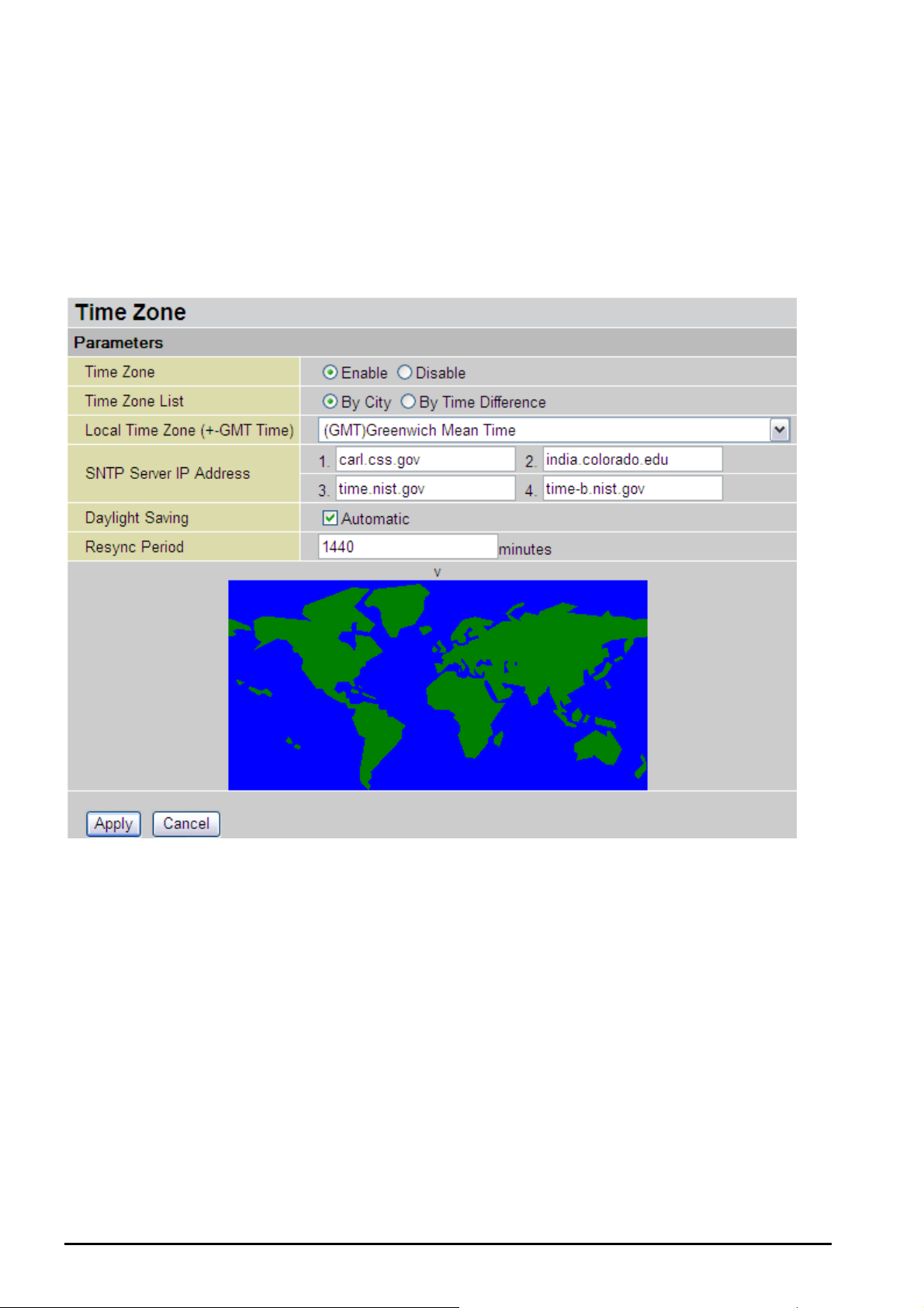
Billion BiPAC 8500/8501/8520/8521 SHDSL (VPN) Firewall Bridge/ Router
System
Listed are items within the System section: Time Zone, Remote Access, Firmware Upgrade,
Backup/Restore, Restart and User Management.
Time Zone
The router does not have a real time clock on board; instead, it uses the Simple Network Time
Protocol (SNTP) to get the current time from an SNTP server outside your network. Choose
your local time zone, click Enable and click the Apply button. After a successful connection to
the Internet, the router will retrieve the correct local time from the SNTP server you have
specified. If you prefer to specify an SNTP server other than those in the list, simply enter its IP
address as shown above. Your ISP may provide an SNTP server for you to use.
• Daylight Saving is also known as Summer Time Period. Many places in the world
adapt it during summer time to move one hour of daylight from morning to the evening in
local standard time. Check Automatic box to auto set your local time.
• Resync Period (in minutes) is the periodic interval the router will wait before it re-
synchronizes the router’s time with that of the specified SNTP server. In order to avoid
unnecessary increase of the load on your specified SNTP server you should keep the
poll interval as high as possible – at the absolute minimum every few hours or even days.
Chapter 4: Configuration
74

Billion BiPAC 8500/8501/8520/8521 SHDSL (VPN) Firewall Bridge/ Router
Remote Access
To temporarily permit remote administration of the router (i.e. from outside your LAN), select a
time period the router will permit remote access and click Enable. You may change other
configuration options for the web administration interface using Device Management options in
the Advanced section of the GUI.
If you wish to permanently enable remote access, choose a time period of 0 minutes.
Chapter 4: Configuration
75

Billion BiPAC SHDSL/SHDSL.bis (VPN) Firewall Bridge/ Router
Warning
Firmware Upgrade
Your router’s “firmware” is the software that allows it to operate and provides all its functionality.
Think of your router as a dedicated computer, and the firmware as the software it runs. Over
time this software may be improved and modified, and your router allows you to upgrade the
software it runs to take on advantage of these changes.
Clicking on Browse will allow you to select the new firmware image file you have downloaded
to your PC. Once the correct file is selected, click Upgrade to update the firmware in your router.
DO NOT power down the router or interrupt the firmware upgrading
while it is still in process. Improper operation could damage the router.
Chapter 4: Configuration
76

Billion BiPAC SHDSL/SHDSL.bis (VPN) Firewall Bridge/ Router
Backup / Restore
These functions allow you to save and to create a backup of your router current settings to a file
on your PC, or to restore a previously saved setting. This is useful if you wish to experiment
with different settings, knowing that you have a backup in hand in case any mistakes occur. It is
advisable to backup your router’s settings before making any significant changes to your
router’s configuration.
Press Backup to select where on your local PC you want to save the setting file. You may also
change the name of the file when saving if you wish to keep multiple backups.
Press Browse to select a file from your PC to restore. You should only restore settings files that
have been generated by the Backup function using the current version of the router’s firmware.
Settings files saved to your PC should not be manually edited in any way.
After selecting the settings file you wish to use, pressing Restore will load those settings into
the router.
77
Chapter 4: Configuration

Billion BiPAC SHDSL/SHDSL.bis (VPN) Firewall Bridge/ Router
Restart Router
Click Restart with option Current Settings to reboot your router (and restore your last saved
configuration).
If you wish to restart the router using the factory default settings (for example, after a firmware
upgrade or if you have saved an incorrect configuration), select Factory Default Settings to
reset to factory default settings.
You may also reset your router to factory settings by holding the RESET pinhole button on the
back panel of the router for more than 6 seconds whilst the router is turned on.
78
Chapter 4: Configuration

Billion BiPAC 8500/8501/8520/8521 SHDSL (VPN) Firewall Bridge/ Router
User Management
In order to prevent unauthorized access to your router’s configuration interface, all users are
required to login to the system with a password. You can set up multiple user accounts, each
with their own password.
You are able to Edit existing user accounts or Create new user accounts to grant access
permission to the device’s configuration interface. Once you have clicked on Edit, you will see
the following account management window:
You can change the user password, even when the account is active and Valid, as well as add
a comment to each user account. These options are the same for creating a user account, with
the exception that once an account is created you cannot change the username. You cannot
delete the default admin account. However you can delete any other accounts created by
clicking Delete when editing the user account.
You are strongly advised to change the password on the default “admin” account when you
receive your router, and whenever you reset your configuration to Factory Defaults.
Chapter 4: Configuration
79
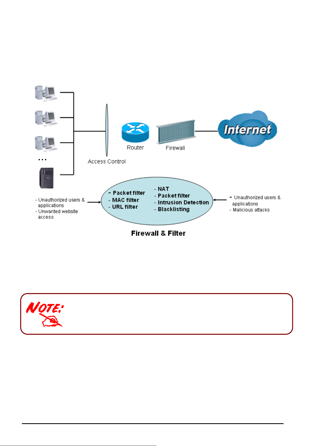
Billion BiPAC 8500/8501/8520/8521 SHDSL (VPN) Firewall Bridge/ Router
Firewall and Access Control
Your router includes a full SPI (Stateful Packet Inspection) firewall for controlling Internet access
from your LAN, as well as helping to prevent attacks from hackers. In addition to this, when
using NAT, the router acts as a “natural” Internet firewall, as all PCs on your LAN will use private
IP addresses that cannot be directly accessed from the Internet.
• Firewall: Prevents access from outside your network. The router provides three levels of
security support:
• NAT natural firewall: This masks LAN users’ IP addresses which is invisible to outside
users on the Internet, making it much more difficult for a hacker to target a machine on
your network. This natural firewall is on when NAT function is enabled.
When using Virtual Servers, your PCs will be exposed at a certain degree
specified in your Virtual Server settings when the ports specified are
opened in your firewall packet filter settings.
• Firewall Security and Policy (General Settings): Inbound direction of Packet Filter
rules to prevent unauthorized computers or applications accessing your local network
from the Internet.
• Intrusion Detection: Enable Intrusion Detection to detect, prevent and log malicious
attacks.
• Access Control: Allow the filtering of unauthorized users from other networks or WAN,
unwanted websites & malicious programs from accessing the local network.
80
Chapter 4: Configuration

Billion BiPAC 8500/8501/8520/8521 SHDSL (VPN) Firewall Bridge/ Router
• Firewall Security and Policy (General Settings): Outbound direction of Packet Filter
rules to prevent unauthorized computers or applications accessing the Internet.
• URL Filter: To block PCs on your local network from unwanted websites.
Listed are items under the Firewall section: General Settings, Packet Filter, Intrusion
Detection, URL Filter, IM/P2P Blocking and Firewall Log.
Chapter 4: Configuration
81

Billion BiPAC 8500/8501/8520/8521 SHDSL (VPN) Firewall Bridge/ Router
General Settings
You can choose not to enable Firewall, you will not able to add filter rules by yourself in the
Packet Filter, or enable the Firewall using preset filter rules and modify the packet filter rules as
required. The Packet Filter is used to filter packets based-on Applications (Port) or IP addresses.
There are four options to choose when you enable Firewall, these are:
• All blocked/User-defined: no pre-defined port or address filter rules by default, meaning
that all inbound (Internet to LAN) and outbound (LAN to Internet) packets will be blocked.
Users have to add their own filter rules for further access to the Internet.
• High/Medium/Low security level: the predefined port filter rules for High, Medium and
Low security are displayed in Port Filters of the Packet Filter.
Select either High, Medium or Low security level to enable Firewall. The only difference
between these three security levels is the preset port filter rules in the Packet Filter. Firewall
functionality is the same for all levels; it is only the list of preset port filters that changes
between each setting. For more detailed on level of preset port filter information, refer to Table
1: Predefined Port Filter.
Note: The changes or added custom filters on a previous security level will be remembered
whenever newer security level is selected. There is no need to reconfigure all settings again if
switching back to the previous level.
The “Block WAN Request” is a stand-alone function and is not affected by whether security is
enabled or disabled. Mostly this is for preventing any scan tools from the hacker from WAN site.
Any remote user who is attempting to perform this action may result in
blocking all the access to configure and management of the device from
the Internet.
82
Chapter 4: Configuration

Billion BiPAC 8500/8501/8520/8521 SHDSL (VPN) Firewall Bridge/ Router
Packet Filter
This function is only available when Firewall is enabled and one of these four security levels is
chosen (All blocked, High, Medium and Low). The predefined port filter rules in the Packet
Filter must modify according to the level of Firewall, which is selected. See Table1: Predefined
Port Filter for more detailed information.
Chapter 4: Configuration
83

Billion BiPAC 8500/8501/8520/8521 SHDSL (VPN) Firewall Bridge/ Router
Example: Predefined Port Filters Rules
The predefined port filter rules for High, Medium and Low security levels are listed. See Table 1.
Note: Firewall – All Blocked/User-defined, you must define and create the port filter rules
yourself. No predefined rule is set
Table 1: Predefined Port Filter
Application Protocol
HTTP(80) TCP(6)
DNS (53) UDP(17)
DNS (53) TCP(6)
FTP(21) TCP(6)
Telnet(23) TCP(6)
SMTP(25) TCP(6)
POP3(110) TCP(6)
NEWS(119) TCP(6)
Port Number
Start End Inbound Outbound Inbound Outbound Inbound Outbound
80 80
53 53 NO
53 53 NO
21 21 NO NO NO
23 23 NO NO NO
25 25 NO
110 110
119 119
Firewall - High Firewall - Medium
NO
NO
NO NO NO
YES
YES
YES
YES
YES
NO
NO
NO
NO
NO
YES
YES YES YES
YES YES YES
YES
YES
YES
YES
YES
Firewall – Low
NO
NO
NO
NO
NO
NO
YES
YES
YES
YES
YES
YES
RealAudio
(7070)
PING ICMP(1) N/A N/A
H.323(1720) TCP(6)
T.120(1503) TCP(6)
SSH(22) TCP(6)
NTP(123) UDP(17) 123 123
HTTPS(443) TCP(6)
ICQ (5190) TCP(6)
UDP(17) 7070 7070
1720 1720
1503 1503
22 22 NO NO NO
443 443
5190 5190
NO NO
NO
NO NO NO
NO NO NO
NO
NO NO NO
NO NO NO
YES
YES
Inbound: Internet to LAN ; Outbound: LAN to Internet.
YES: Allowed ; NO: Blocked ; N/A: Not Applicable
YES YES
NO
NO
YES
YES YES YES
YES YES YES
YES YES YES
YES
YES
NO
YES YES
NO
NO
NO
YES
YES
YES
YES
YES
84
Chapter 4: Configuration

Billion BiPAC 8500/8501/8520/8521 SHDSL (VPN) Firewall Bridge/ Router
Packet Filter – Add TCP/UDP Filter
• Rule Name: User-define description to identify this entry or click to select
existing predefined rules. The maximum name length is 32 characters.
• Time Schedule: It is self-defined time period. You may specify a time schedule for your
prioritization policy. For setup and detail, refer to Time Schedule section
• Source IP Address(es) / Destination IP Address(es): This is the Address-Filter used to
allow or block traffic to/from particular IP address(es). Selecting the Subnet Mask of the
IP address range you wish to allow/block the trafficn direction; set IP address and Subnet
Mask to 0.0.0.0 to inactivate the Address-Filter rule.
Tip: To block access, to/from a single IP address, enter that IP address as the Host IP Address
and use a Host Subnet Mask of “255.255.255.255”.
• Type: It is the packet protocol type used by the application. Select either TCP or UDP or
both of TCP/UDP.
• Source Port: This Port or Port Ranges defines the port allowed to be used by the
Remote/WAN to connect to the application. Default is set from range 0 ~ 65535. It is
recommended that this option be configured by an advanced user.
• Destination Port: This is the Port or Port Ranges that defines the application.
• Inbound / Outbound: Select Allow or Block the access to the Internet (“Outbound”)
or from the Internet (“Inbound”).
Click the Apply button to apply your changes.
85
Chapter 4: Configuration

Billion BiPAC 8500/8501/8520/8521 SHDSL (VPN) Firewall Bridge/ Router
Packet Filter – Add Raw IP Filter
• Rule Name: A user-defined name for identifying the rule.
• Time Schedule: It is self-defined time period. You may specify a time schedule for your
prioritization policy. For setup and detail, refer to Time Schedule section
• Protocol Number: Insert the port number, i.e. GRE 47.
• Inbound / Outbound: Select Allow or Block the access to the Internet (“Outbound”)
or from the Internet (“Inbound”).
Click the Apply button to apply your changes.
86
Chapter 4: Configuration
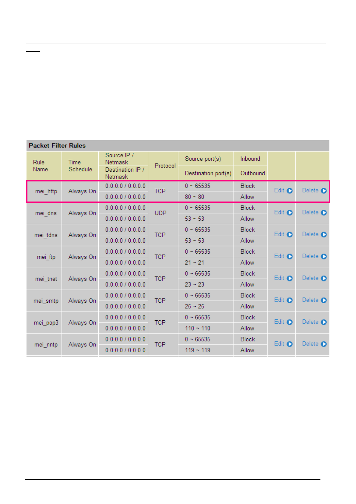
Billion BiPAC 8500/8501/8520/8521 SHDSL (VPN) Firewall Bridge/ Router
Example: Configuring your firewall to allow for a publicly accessible web server on your
LAN
The predefined port filter rule for HTTP (TCP port 80) is the same whether the firewall is set to a
high, medium or low security level. To setup a web server located on the local network when the
firewall is enabled, you have to configure the Port Filters setting for HTTP.
As you can see from the diagram below, when the firewall is enabled with one of the three
presets (Low/Medium/High), inbound HTTP access is not allowed which means remote access
through HTTP to your router is not allowed.
Note: Inbound indicates accessing from Internet to LAN and Outbound is from LAN to the
Internet
87
Chapter 4: Configuration

Billion BiPAC SHDSL/SHDSL.bis (VPN) Firewall Bridge/ Router
Configuring Packet Filter:
1. Click Port Filters. You will then be presented with the predefined port filter rules screen (in
this case for the low security level), shown below:
Note: You may click Edit the predefined rule instead of Delete it. This is an example to
show to how you add a filter on your own.
Click Delete
2. Click Delete to delete the existing HTTP rule.
3. Click Add TCP/UDP Filter.
Click Add TCP/UDP Filter
4. Input the Rule Name, Time Schedule, Source/Destination IP, Type, Source/Destination Port,
Inbound and Outbound.
Example:
Application: Cindy_HTTP
Time Schedule: Always On
Source / Destination IP Address(es): 0.0.0.0 (I do not wish to activate the address-filter,
instead I use the port-filter)
Type: TCP (Please refer to Table1: Predefined Port Filter)
Source Port: 0-65535 (I allow all ports to connect with the application)
Redirect Port: 80-80 (This is Port defined for HTTP)
Inbound / Outbound: Allow
Chapter 4: Configuration
88
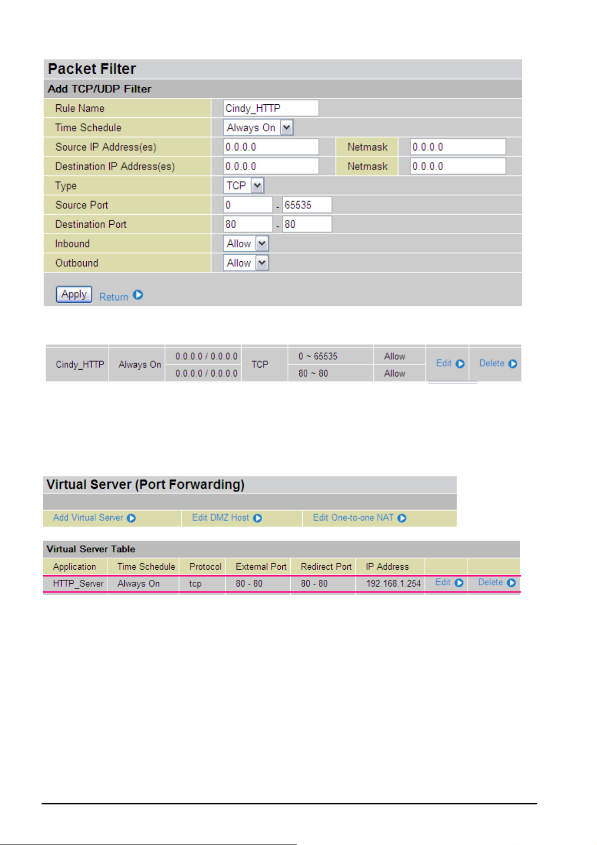
Billion BiPAC 8500/8501/8520/8521 SHDSL (VPN) Firewall Bridge/ Router
5. The new port filter rule for HTTP is shown below:
6. Configure your Virtual Server (“port forwarding”) settings so that incoming HTTP requests
on port 80 will be forwarded to the PC running your web server:
Note: For how to configure the HTTP in Virtual Server, go to Add Virtual Server in Virtual
Server section for more details.
.
Chapter 4: Configuration
89

Billion BiPAC SHDSL/SHDSL.bis (VPN) Firewall Bridge/ Router
Intrusion Detection
The router’s Intrusion Detection System (IDS) is used to detect hacker attacks and intrusion
attempts from the Internet. If the IDS function of the firewall is enabled, inbound packets are
filtered and blocked depending on whether they are detected as possible hacker attacks,
intrusion attempts or other connections that the router determines to be suspicious.
Blacklist: If the router detects a possible attack, the source IP or destination IP address will be
added to the Blacklist. Any further attempts using this IP address will be blocked for the time
period specified as the Block Duration. The default setting for this function is false (disabled).
Some attack types are denied immediately without using the Blacklist function, such as Land
attack and Echo/CharGen scan.
• Intrusion Detection: If enabled, IDS will block Smurf attack attempts. Default is false.
• Block Duration:
o Victim Protection Block Duration: This is the duration for blocking Smurf attacks.
Default value is 600 seconds.
o Scan Attack Block Duration: This is the duration for blocking hosts that attempt
a possible Scan attack. Scan attack types include X’mas scan, IMAP SYN/FIN
scan and similar attempts. Default value is 86400 seconds.
o DOS Attack Block Duration: This is the duration for blocking hosts that attempt a
possible Denial of Service (DoS) attack. Possible DoS attacks this attempts to
block include Ascend Kill and WinNuke. Default value is 1800 seconds.
• Max TCP Open Handshaking Count: This is a threshold value to decide whether a
SYN Flood attempt is occurring or not. Default value is 100 TCP SYN per seconds.
• Max PING Count: This is a threshold value to decide whether an ICMP Echo Storm is
occurring or not. Default value is 15 ICMP Echo Requests (PING) per second.
• Max ICMP Count: This is a threshold to decide whether an ICMP flood is occurring or
not. Default value is 100 ICMP packets per seconds except ICMP Echo Requests
90
Chapter 4: Configuration

Billion BiPAC 8500/8501/8520/8521 SHDSL (VPN) Firewall Bridge/ Router
SYN/FIN/RST/ACK
(PING).
For SYN Flood, ICMP Echo Storm and ICMP flood, IDS will just warn the user in the Event Log.
It cannot protect against such attacks. Table 2: Types of Hacker attack recognized by the IDS.
1
Detect
Parameter
Blacklist
Ascend Kill Ascend Kill data Src IP
Type of
Block
Duration
Drop
Packet
DoS Yes Yes
TCP
WinNuke
Port 135,
137~139, Flag:
Src IP
DoS Yes Yes
URG
Smurf
ICMP type 8
Des IP is
broadcast
Dst IP
Victim
Protection
Yes Yes
Land attack SrcIP = DstIP Yes Yes
Echo/CharGen
Scan
Echo Scan
CharGen Scan
X’mas Tree Scan
UDP Echo Port
and CharGen
Port
UDP Dst Port =
Echo(7)
UDP Dst Port =
CharGen(19)
TCP Flag:
X’mas
Yes Yes
Src IP
Src IP
Src IP
Scan Yes Yes
Scan Yes Yes
Scan Yes Yes
TCP Flag:
SYN/FIN
IMAP
SYN/FIN Scan
DstPort:
IMAP(143)
Src IP
Scan Yes Yes
SrcPort: 0 or
65535
TCP,
No Existing
Scan
session And
Scan Hosts
Src IP
Scan Yes Yes
more than five.
TCP
No Existing
session
Net Bus Scan
DstPort = Net
SrcIP Scan Yes Yes
Bus
12345,12346,
3456
UDP, DstPort =
Back Orifice Scan
Orifice Port
SrcIP Scan Yes Yes
(31337)
Max TCP Open
SYN Flood
Handshaking
Count (Default
Yes
100 c/sec)
Show Log
Chapter 4: Configuration
91

Billion BiPAC 8500/8501/8520/8521 SHDSL (VPN) Firewall Bridge/ Router
Max ICMP
ICMP Flood
Count (Default
Yes
100 c/sec)
Max PING
ICMP Echo
Count
(Default 15
Yes
c/sec)
Src IP: Source IP Src Port: Source Port
Dst Port: Destination Port Dst IP: Destination IP
92
Chapter 4: Configuration

Billion BiPAC 8500/8501/8520/8521 SHDSL (VPN) Firewall Bridge/ Router
URL Filtering
URL (Uniform Resource Locator – e.g. an address in the form of http://www.abcde.com or
http://www.example.com) filter rules allow you to prevent users on your network from accessing
particular websites by their URL. There are no pre-defined URL filter rules; you can add filter
rules to meet your requirements.
• Enable/Disable: To enable or disable URL Filter feature.
• Block Mode: A list of modes that you can choose from to check the URL filter rules.
o Disabled: No action will be performed by the Block Mode.
o Always On: Action is enabled. URL filter rules will be monitoring and checking at
all hours of the day.
o TimeSlot1 ~ TimeSlot16: It is self-defined time period. You may specify the time
period to check the URL filter rules, i.e. during working hours. For setup and detail,
refer to Time Schedule section.
• Keywords Filtering: Allow blocking by specific keywords within a particular URL rather
than having to specify a complete URL (e.g. to block any image called
“advertisement.gif”). When enabled, your specified keywords list will be checked to see if
any keywords are present in URLs accessed to determine if the connection attempt
should be blocked. Please note that the URL filter blocks web browser (HTTP)
connection attempts using port 80 only.
For example, if the URL is http://www.abc.com/abcde.html, it will be dropped if the keyword
“abcde” occurs in the URL.
• Domains Filtering: This function checks the whole URL accessed and not just the IP
address in URLs against your list of domains to block or to allow. If it is matched, the
URL request will be sent (Trusted) or dropped (Forbidden). For this function to be
activated, both check-boxes must be checked. Below is the checking procedure:
1. Check the domain in the URL to determine if it is in the trusted list. If yes, the connection
attempt is sent to the remote web server.
2. If not, check if it is listed in the forbidden list. If yes, then the connection attempt will be
93
Chapter 4: Configuration

Billion BiPAC 8500/8501/8520/8521 SHDSL (VPN) Firewall Bridge/ Router
dropped.
3. If the packet does not match either of the above two items, it is sent to the remote web server.
4. Please be noted that the completed URL, “www” + domain name, shall be specified. For
example to block traffic to www.google.com.au, enter “www.google” or “www.google.com”
In the example below, the URL request for www.abc.com will be sent to the remote web server
because it is listed in the trusted list, whilst the URL request for www.google or www.google.com
will be dropped, because www.google is in the forbidden list.
Example: Andy wishes to disable all WEB traffic except for the ones listed in the trusted
domain list, which would prevent Bobby from accessing other web sites. Andy selects both
functions in the Domain Filtering and thinks that it will stop Bobby. Nevertheless, Bobby knows
that Domain Filtering will ONLY disable all WEB traffic except for the one in the Trusted
Domain, BUT not its IP address. If this is the situation, Block surfing by IP address function
can be handy and helpful to Andy. With this feature, Andy can prevent Bobby from accessing
unwanted websites.
• Restrict URL Features: This function enhances the restriction to your URL rules.
o Block Java Applet: This function can block Web content that includes the Java
Applet. It is to prevent someone who wants to damage your system via standard
HTTP protocol.
o Block surfing by IP address: Preventing someone who uses the IP address as
URL for skipping Domains Filtering function. Activate only and if Domain Filtering
is enabled.
94
Chapter 4: Configuration

Billion BiPAC 8500/8501/8520/8521 SHDSL (VPN) Firewall Bridge/ Router
IM / P2P Blocking
IM, short for Instant Message, is required to use client program software that allows users to
communicate, in exchanging text message, with other IM users in real time over the Internet. A
P2P application, known as Peer-to-peer, is a group of computer users who share files with
specific groups of people across the Internet. Both Instant Message and Peer-to-peer
applications make communication faster and easier but your network can become increasingly
insecure at the same time. Billion’s IM and P2P blocking helps to restrict LAN PCs from
accessing the commonly used IM such as Yahoo and MSN, and P2P, BitTorrent and eDonkey
applications over the Internet.
• Instant Message Blocking: The default is set to Disabled.
o Disabled: Instant Message blocking is not triggered. No action will be performed.
o Always On: Action is enabled.
o TimeSlot1 ~ TimeSlot16: This is the self-defined time period. You may specify
the time period to trigger the blocking, i.e. during working hours. For setup and
detail, refer to Time Schedule section.
• Yahoo/MSN Messenger: Check the box to block either or both Yahoo or/and MSN
Messenger. Be sure you enabled the Instant Message Blocking first.
• Peer to Peer Blocking: The default is set to Disabled.
o Disabled: Instant Message blocking is not triggered. No action will be performed.
o Always On: Action is enabled.
o TimeSlot1 ~ TimeSlot16: This is the self-defined time period. You may specify
the time period to trigger the blocking, i.e. during working hours. For setup and
detail, refer to Time Schedule section.
• BitTorrent / eDonkey: Check the box to block either or both Bit Torrent or/and eDonkey.
Be sure you enabled the Peer to Peer Blocking first.
95
Chapter 4: Configuration

Billion BiPAC SHDSL/SHDSL.bis (VPN) Firewall Bridge/ Router
Firewall Log
Firewall Log displays log information of all unexpected action taken by your firewall settings.
Check the Enable box to activate the logs.
Log information can be seen in the Status – Event Log after enabling.
Chapter 4: Configuration
96
 Loading...