

Page 1

BiPAC 7800
Dual WAN
ADSL2+ Firewall Router
User Manual
Version released 1.01
Last revised date 11-11-2008
Page 2

Table of Contents
Chapter 1: Introduction ..................................................................... 1
Introduction to your Router ..................................................................1
Features ............................................................................................2
Chapter 2: Installing the Router ....................................................... 4
Important note for using this router ....................................................4
Package Contents .................................................................................5
The Front LEDs. ................................................................................6
Cabling ................................................................................................8
Chapter 3: Basic Installation ...........................................................9
Connecting Your Router .....................................................................10
Network Conguration ........................................................................ 11
Factory Default Settings .....................................................................17
Information from your ISP ................................................................18
Chapter 4: Conguration ................................................................19
Quick Start ............................................................................................20
Status (Basic Mode) ............................................................................27
Coguration (Basic Mode) .................................................................28
WAN – Main Port (ADSL) ..................................................................28
WAN Prole – Main Port (EWAN) .....................................................33
Status (Advanced Mode) .................................................................... 35
ADSL .................................................................................................36
ARP ...................................................................................................37
DHCP ................................................................................................37
System Log ....................................................................................... 38
Conguration (Advanced Mode) .......................................................39
LAN ...................................................................................................39
Ethernet ..........................................................................................39
IP Alias ............................................................................................ 39
DHCP Server ................................................................................... 40
Page 3

WAN ..................................................................................................41
WAN Prole (ADSL) ..........................................................................41
WAN Prole – Main Port (EWAN) .........................................................47
ADSL Mode .....................................................................................49
System ..............................................................................................50
Time Zone .......................................................................................50
Firmware Upgrade ............................................................................50
Backup / Restore ..............................................................................51
Restart ............................................................................................52
User Management .............................................................................52
Firewall ..............................................................................................53
Packet Filter ..................................................................................... 53
MAC Filter .......................................................................................54
Block WAN Ping ...............................................................................54
Virtual Server ....................................................................................55
Port Mapping ....................................................................................56
DMZ ...............................................................................................57
Advanced .......................................................................................... 58
Static Route .....................................................................................58
Dynamic DNS ...................................................................................58
VLAN ..............................................................................................59
Device Management .......................................................................... 60
IGMP .............................................................................................. 66
TR-069 Client ...................................................................................66
Remote Access .................................................................................67
Appendix: Product Support & Contact .......................................... 68
Page 4

Chapter 1: Introduction
Introduction to your Router
Thank you for purchasing BiPAC 7800 Router. Your new router is an all-in-one unit that combines
an ADSL modem, ADSL2/2+ router and Ethernet network switch to provide everything you need to
get the machines on your network connected to the Internet over an ADSL broadband connection.
The BiPAC 7800 router complies with ADSL2+ standards for deployment worldwide and supports
downstream rates of up to 24 Mbps and upstream rates of up to 1 Mbps. Designed for small ofce,
home ofce and residential users, the router enables even faster Internet connections. You can
enjoy ADSL services and broadband multimedia applications such as interactive gaming, video
streaming and real-time audio much easier and faster than ever before.
The BiPAC 7800 supports PPPoA (RFC 2364 – PPP (Point-to-Point Protocol) over ATM Adaptation
Layer 5), RFC 1483 encapsulation over ATM (bridged or routed), PPP over Ethernet (RFC 2516)
to establish a connection with your ISP. Your new router also supports VC-based and LLC-based
multiplexing.
The perfect solution for connecting a small group of PCs to a high-speed broadband Internet
connection, the BiPAC 7800 allows multiple users to have high-speed Internet access
simultaneously.
Your new router also serves as an Internet rewall, protecting your network from access by
outside users. Not only does it provide a natural rewall function with Network Address Translation
(NAT), it also provides rich rewall features to secure your network. All incoming data packets
are monitored and ltered. You can also congure your new router to block internal users from
accessing the Internet.
The BiPAC 7800 provides two levels of security support. First, it masks LAN IP addresses making
them invisible to outside users on the Internet, so it is much more difcult for a hacker to target a
machine on your network. Second, it can block and redirect certain ports to limit the services that
outside users can access. To ensure that games and other Internet applications run properly, you
can open specic ports for outside users to access internal services on your network.
The Integrated DHCP (Dynamic Host Control Protocol) client and server services allow multiple
users to get IP addresses automatically when the router boots up. Simply set local machines as
a DHCP client to accept a dynamically assigned IP address from the DHCP server and reboot.
Each time a local machine is powered up; the router recognizes it and assigns an IP address to
instantly connect it to the LAN.
For advanced users, Virtual Service (port mapping) functions allow the product to provide limited
visibility to local machines with specic services for outside users. For instance, a dedicated web
server can be connected to the Internet via the router and then incoming requests for web pages
that are received by the router can be rerouted to your dedicated local web server, even though
the server now has a different IP address.
Virtual Server can also be used to re-task services to multiple servers. For instance, you can set the
router to allow separated FTP, Web, and Multiplayer game servers to share the same Internet-visible
IP address while still protecting the servers and LAN users from hackers.
1
Page 5

Features
Express Internet Access
The router complies with ADSL worldwide standards. It supports downstream rate up to 12/24
Mbps with ADSL2/2+, 8Mbps with ADSL. Users enjoy not only high-speed ADSL services but also
broadband multimedia applications such as interactive gaming, video streaming and real-time audio
much easier and faster than ever. It is compliant with Multi-Mode standard (ANSI T1.413, Issue 2;
G.dmt (ITU G.992.1); G.lite (ITU G.992.2); G.hs (ITU G994.1); G.dmt.bis (ITU G.992.3); G.dmt.bis.
plus (ITU G.992.5)).
EWAN
Besides using ADSL to get connected to the Internet, BiPAC 7800 offers its Ethernet port 5 as a WAN
port to be used to connect to Cable Modems, VDSL, ber optic lines and PON. This alternative, yet
faster method to connect to the internet will provide users more exibility to get online.
Fast Ethernet Switch
A 4-port 1000Mbps fast Ethernet switch is built in with automatic switching between MDI and MDI-X.
An Ethernet straight or crossover cable can be used directly for auto detection.
Multi-Protocol to Establish a Connection
It supports PPPoA (RFC 2364 - PPP over ATM Adaptation Layer 5), RFC 1483 encapsulation
overATM (bridged or routed), PPP over Ethernet (RFC 2516), and IPoA (RFC1577) to establish a
connection with the ISP. The product also supports VC-based and LLC-based multiplexing.
PPP over Ethernet (PPPoE)
The BiPAC 7800 provides an embedded PPPoE client function to establish a connection. You
get greater access speed without changing the operation concept, while sharing the same ISP
account and paying for one access account. No PPPoE client software is required for the local
computer. Automatic Reconnect and Disconnect Timeout (Idle Timer) functions are also provided.
Universal Plug and Play (UPnP) and UPnP NAT Traversal
This protocol is used to enable simple and robust connectivity among stand-alone devices and PCs
from many different vendors. It makes network simple and affordable for users. UPnP architecture
leverages TCP/IP and the Web to enable seamless proximity networking in addition to control and
data transfer among networked devices. With this feature enabled, users can now connect to Net
meeting or MSN Messenger seamlessly.
Network Address Translation (NAT)
Allows multi-users to access outside resources such as the Internet simultaneously with one IP
address/one Internet access account. Many application layer gateway (ALG) are supported such as
web browser, ICQ, FTP, Telnet, E-mail, News, Net2phone, Ping, NetMeeting, IP phone and others.
2
Page 6

Domain Name System (DNS) Relay
It provides an easy way to map the domain name (a friendly name for users such as www.yahoo.
com) and IP address. When a local machine sets its DNS server with this router’s IP address, every
DNS conversion request packet from the PC to this router will be forwarded to the real DNS in the
outside network.
Dynamic Domain Name System (DDNS)
The Dynamic DNS service allows you to alias a dynamic IP address to a static hostname. This
dynamic IP address is the WAN IP address. For example, to use the service, you must rst apply
for an account from a DDNS service like http://www.dyndns.org/. More than 5 DDNS servers are
supported.
Virtual Server
Users can specify some services to be visible from outside users. The router can detect incoming
service requests and forward either a single port or a range of ports to the specic local computer
to handle it. For example, a user can assign a PC in the LAN acting as a WEB server inside and
expose it to the outside network. Outside users can browse inside web servers directly while it is
protected by NAT. A DMZ host setting is also provided to a local computer exposed to the outside
network, Internet.
Rich Packet Filtering
Not only lters the packet based on IP address, but also based on Port numbers. It will filter packets
from and to the Internet, and also provides a higher level of security control.
Dynamic Host Conguration Protocol (DHCP) Client and Server
In the WAN site, the DHCP client can get an IP address from the Internet Service Provider (ISP)
automatically. In the LAN site, the DHCP server can allocate a range of client IP addresses and
distribute them including IP address, subnet mask as well as DNS IP address to local computers. It
provides an easy way to manage the local IP network.
Web based GUI
It supports web based GUI for conguration and management. It is user-friendly and comes with online help. It also supports remote management capability for remote users to congure and manage
this product.
Firmware Upgradeable
Device can be upgraded to the latest rmware through the WEB based GUI.
3
Page 7
Chapter 2: Installing the Router
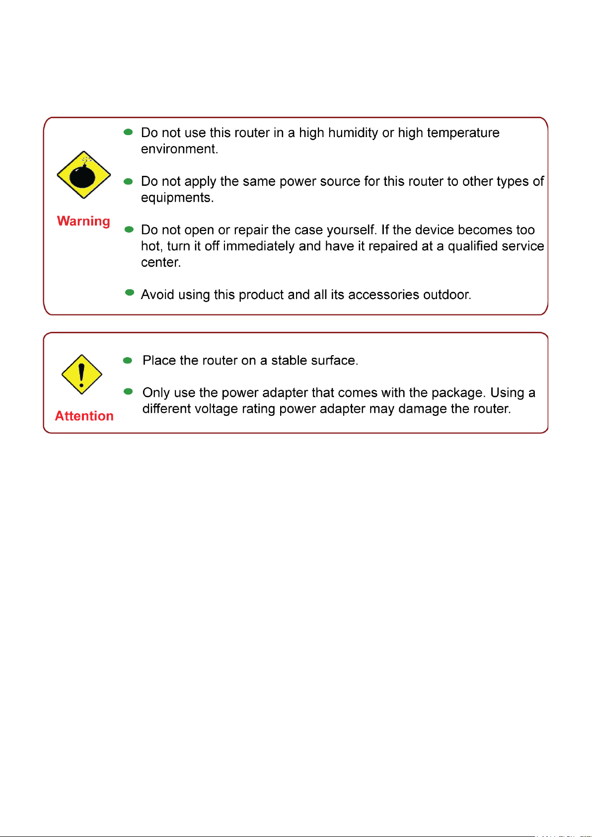
Important note for using this router
4
Page 8
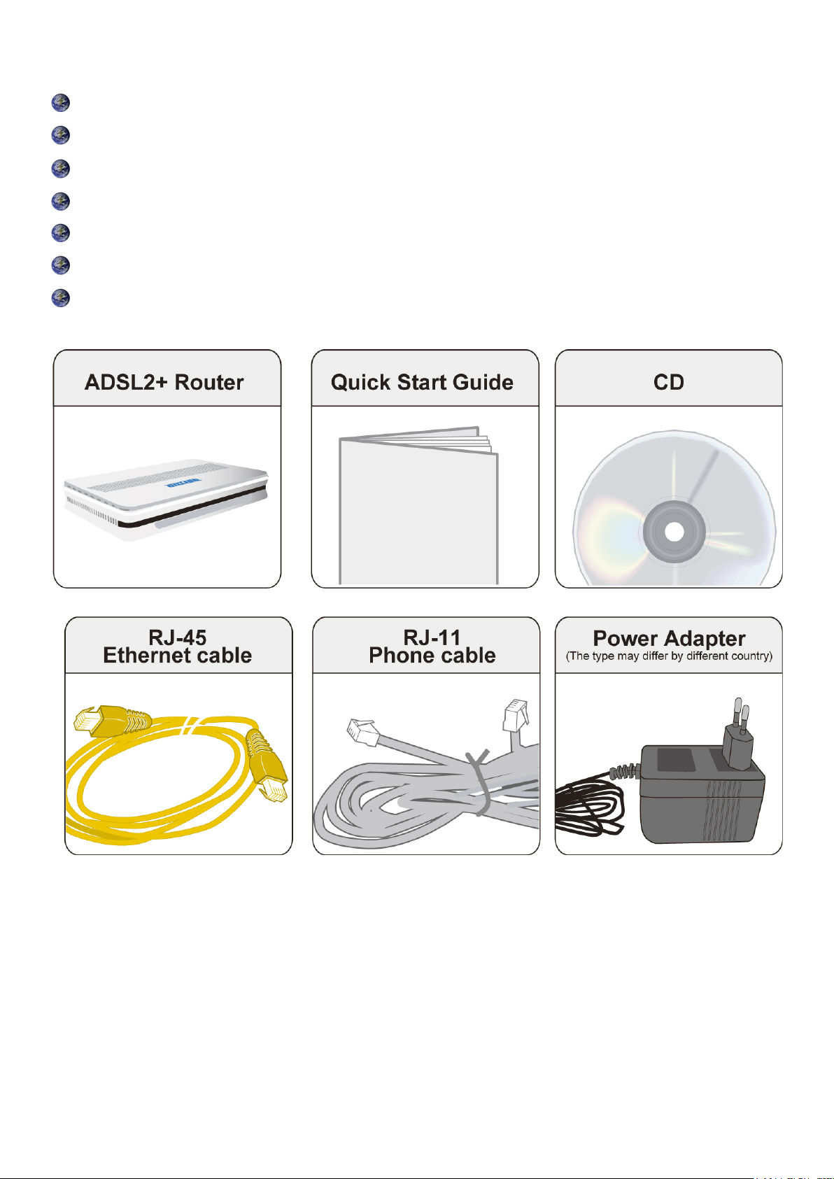
Package Contents
BiPAC 7800 Dual WAN ADSL2+ Firewall Router
CD containing the online manual
RJ-11 ADSL/Telephone cable
Ethernet (RJ-45) cable
Power adapter
Quick Start Guide
Splitter / Microlter (Optional)
5
Page 9
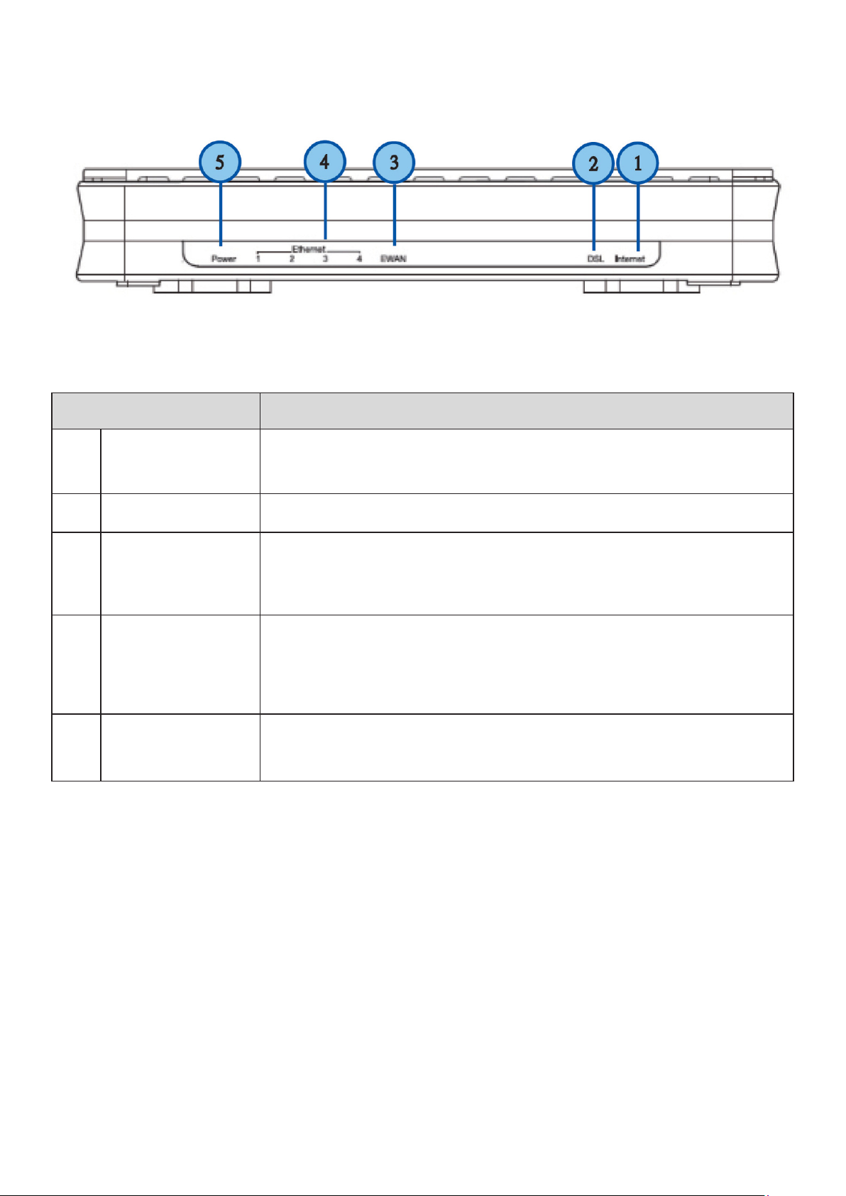
The Front LEDs.
LED Meaning
1 Internet
2 DSL
Lit red when WAN port fails to get IP address.
Flash green when WAN port gets IP address successfully and when
data is transmitted.
Lit Green when the device is successfully connected to an ADSL
DSLAM. (“line sync”).
Lit when connected to a broadband connection device.
3 EWAN
Ethernet port
4
1X — 4X
(RJ-45 connector)
5 Power
Lit orange for 10/100Mbps.
Blinking when data is Transmitted / Received.
Lit when one of LAN ports is connected to an Ethernet device.
Lit green when the speed of transmission hits 1000Mbps; Lit orange
when the speed of transmission hits 10/100Mbps.
Blink when data is being Transmitted / Received.
When the power is plugged in, it will lit Red. When the system
is ready, it will lit Green. While the system is rebooting or during
rmware upgrade, the LED light will ash.
6
Page 10
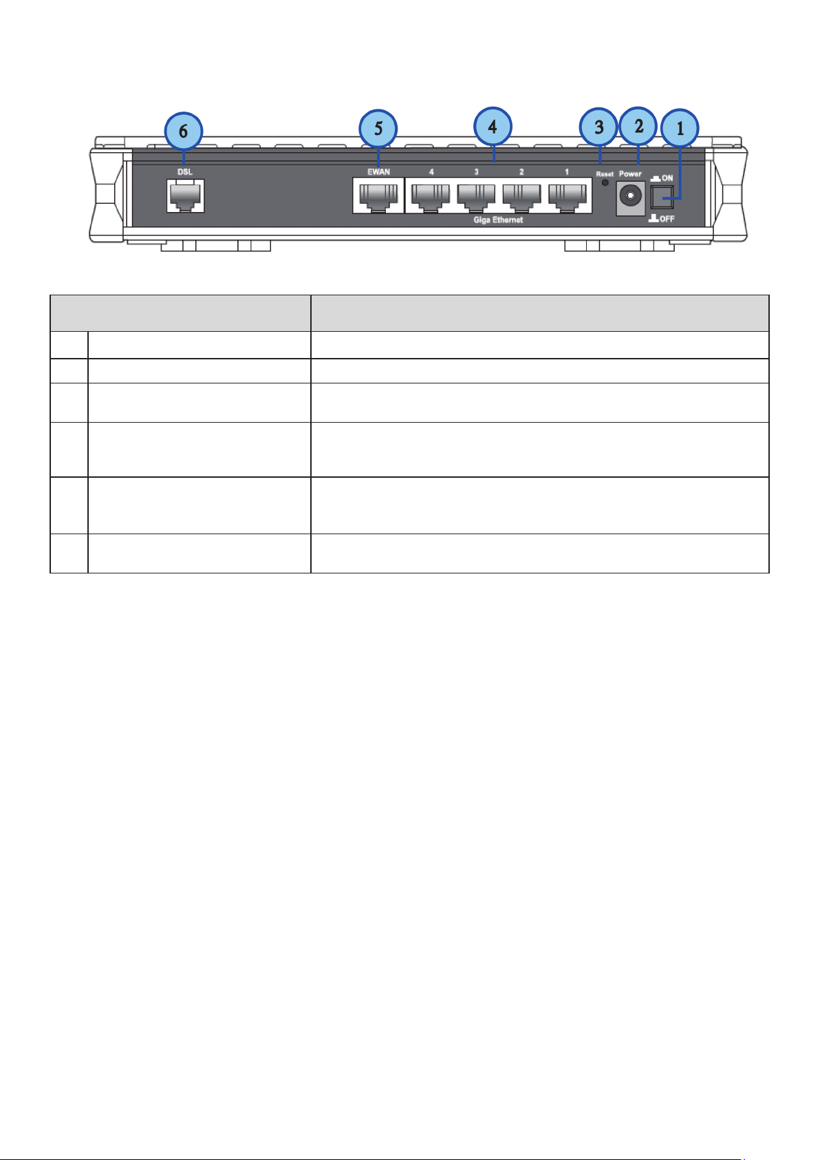
The Rear Ports
Port Meaning
1 Power Switch Power ON/OFF switch.
2 Power Connect it with the supplied power adapter.
3 RESET
4 Giga Ethernet
5 EWAN
6 DSL
Press more than 1 second to restore the device to its default
mode.
Connect to a PC or an ofce/home network of 10Mbps,
100Mbps or 1000Mbps using the provided RJ-45 Ethernet
cables.
WAN 10/100Mbps Ethernet port (with auto crossover
support). Connect Cable Modem, VDSL, and Fiber Modem
or PON optic lines with your RJ-45 cable.
Connect this port to the ADSL/telephone network with the
RJ-11 cable (telephone) provided.
7
Page 11

Cabling
One of the most common causes of problem is bad cabling or ADSL line(s). Make sure that all
connected devices are turned on. On the front panel of your router is a bank of LEDs. Verify that the
LAN Link and ADSL line LEDs are lit. If they are not, verify if you are using the proper cables.
Make sure that all devices (e.g. telephones, fax machines, analogue modems) connected to the same
telephone line as your router have a line lter connected between them and the wall outlet (unless
you are using a Central Splitter or Central Filter installed by a qualied and licensed electrician),
and that all line lters are correctly installed in a right way. If line lter is not installed and connected
properly, it may cause problem to your ADSL connection or may result in frequent disconnections.
8
Page 12

Chapter 3: Basic Installation
The router can be congured through your web browser. A web browser is included as a standard
application in the following operating systems: Linux, Mac OS, Windows 98/NT/2000/XP/Me/Vista,
etc. The product provides an easy and user-friendly interface for conguration.
Please check your PC network components. The TCP/IP protocol stack and Ethernet network
adapter must be installed. If not, please refer to your Windows-related or other operating system
manuals.
There are ways to connect the router, either through an external repeater hub or connect directly
to your PCs. However, make sure that your PCs have an Ethernet interface installed properly prior
to connecting the router device. You ought to congure your PCs to obtain an IP address through
a DHCP server or a xed IP address that must be in the same subnet as the router. The default IP
address of the router is 192.168.1.254 and the subnet mask is 255.255.255.0 (i.e. any attached PC
must be in the same subnet, and have an IP address in the range of 192.168.1.1 to 192.168.1.253).
The best and easiest way is to congure the PC to get an IP address automatically from the router
using DHCP. If you encounter any problem accessing the router web interface it is advisable to
uninstall your rewall program on your PCs, as they can cause problems accessing the IP address
of the router. Users should make their own decisions on what is best to protect their network.
Please follow the following steps to congure your PC network environment.
9
Page 13
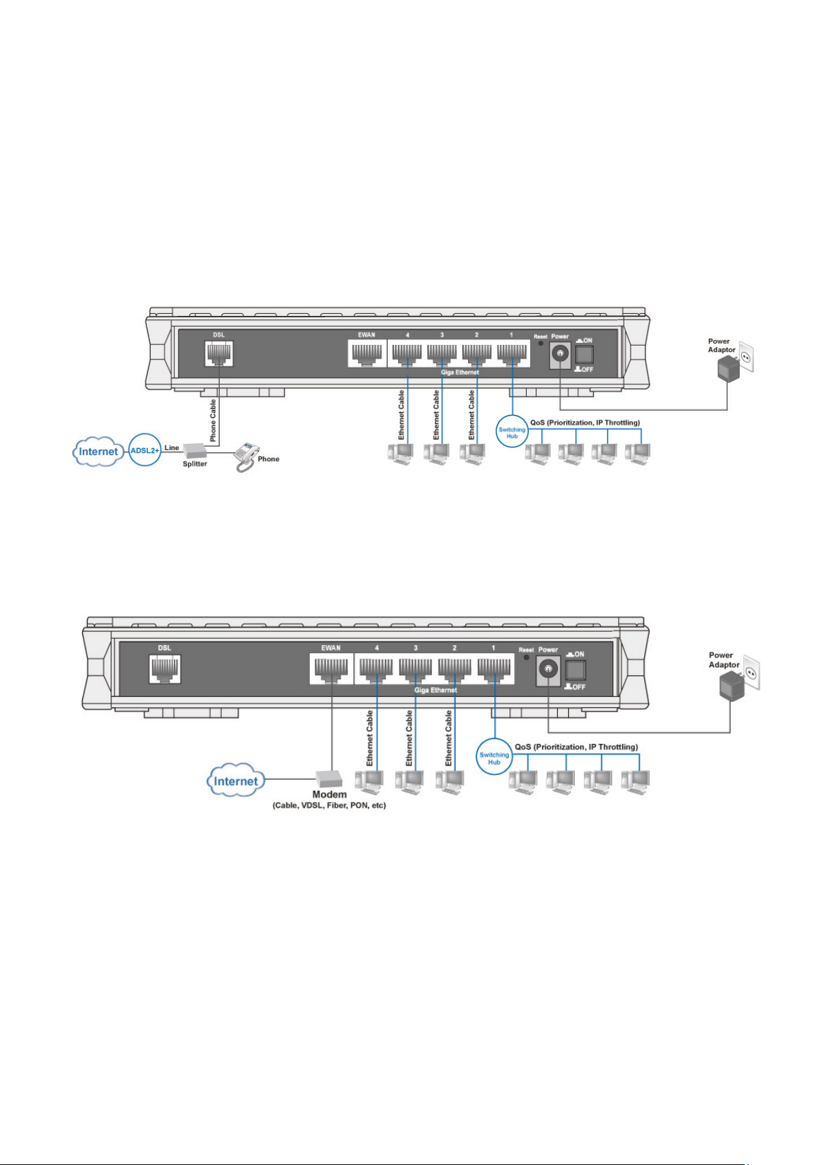
Connecting Your Router
Users will not be able to connect to the internet through EWAN if DSL is already connected to the
internet. Only one connection type (EWAN or DSL) is allowed to connect to the internet at one
time.
ADSL Router Mode
Broadband Router Mode
10
Page 14
Network Conguration
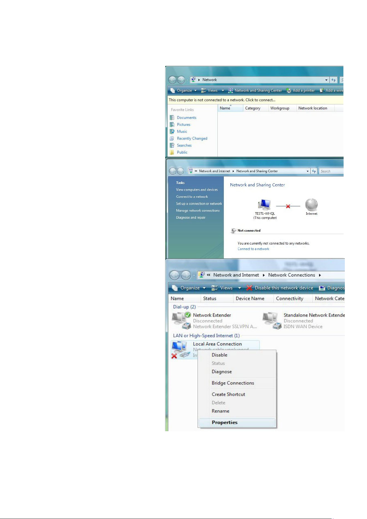
Conguring PC in Windows Vista
Go to Start. Click on Network.1.
Then click on Network and Sharing 2.
Center at the top bar.
When the Network and Sharing 3.
Center window pops up, select and
click on Manage network connections on the left window column.
Select the Local Area Connection, 4.
and right click the icon to select
Properties.
11
Page 15
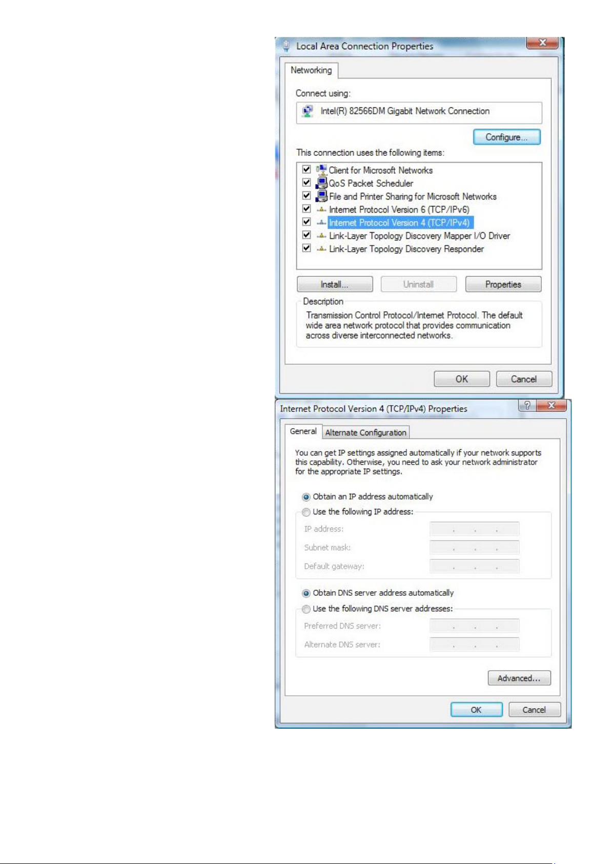
Select Internet Protocol Version 4 5.
(TCP/IPv4) then click Properties.
In the TCP/IPv4 properties window, 6.
select the Obtain an IP address automatically and Obtain DNS Server
address automatically radio buttons. Then click OK to exit the setting.
Click OK again in the Local Area 7.
Connection Properties window to
apply the new conguration.
12
Page 16
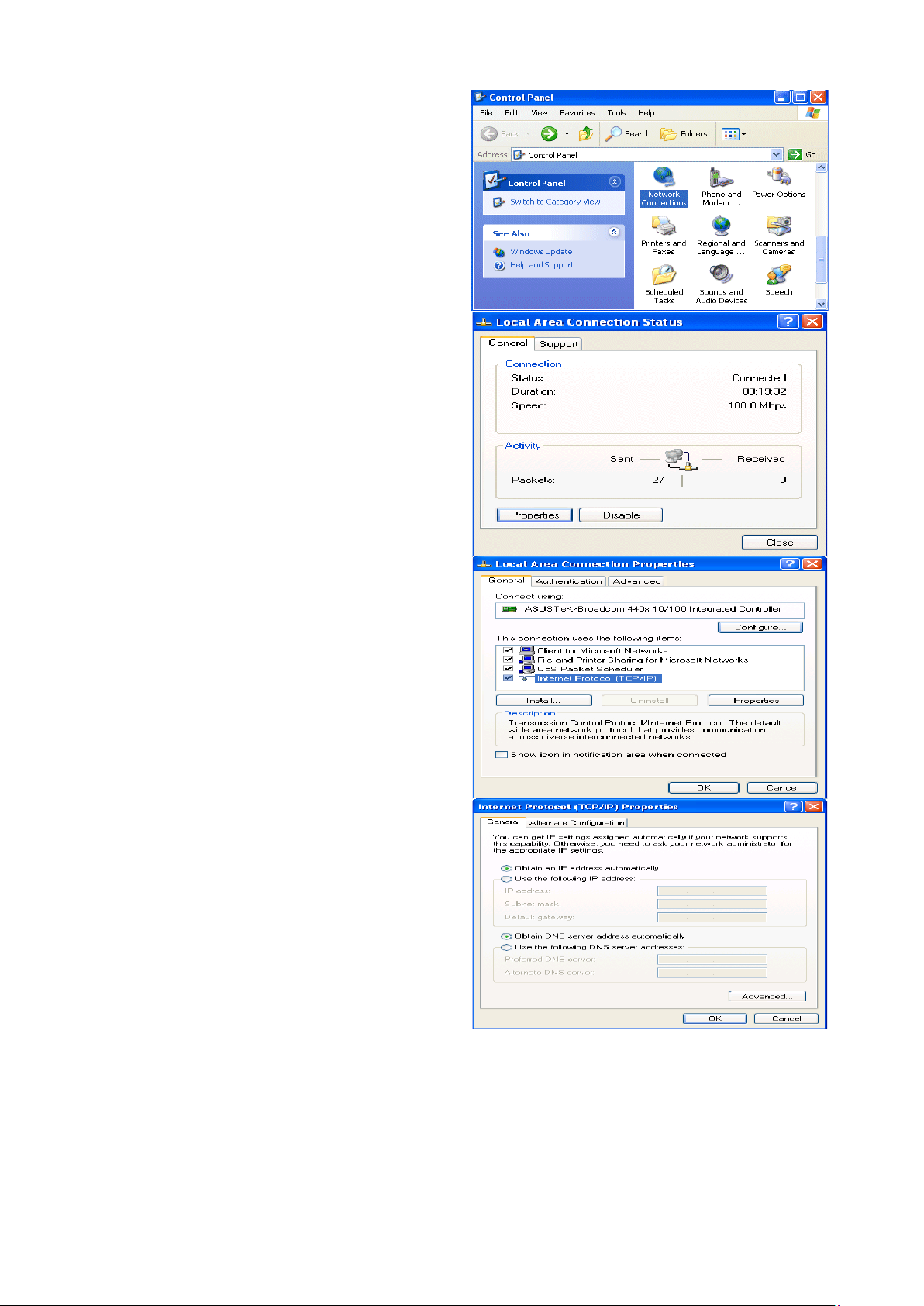
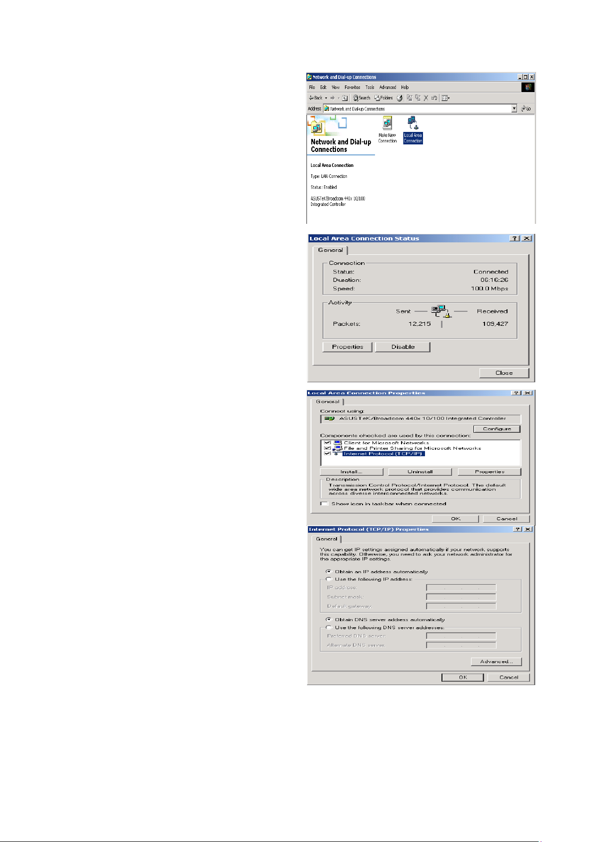
Conguring PC in Windows XP
Go to Start > Control Panel (in Classic 1.
View). In the Control Panel, double-click
on Network Connections
Double-click Local Area Connection.2.
In the Local Area Connection Status 3.
window, click Properties.
Select Internet Protocol (TCP/IP) and 4.
click Properties.
Select the Obtain an IP address auto-5.
matically and the Obtain DNS server
address automatically radio buttons.
Click OK to nish the conguration.6.
13
Page 17
Conguring PC in Windows 2000
Go to Start > Settings > Control Panel. 1.
In the Control Panel, double-click on
Network and Dial-up Connections.
Double-click Local Area Connection.2.
In the Local Area Connection Status 3.
window click Properties.
Select Internet Protocol (TCP/IP) and 4.
click Properties.
Select the Obtain an IP address auto-5.
matically and the Obtain DNS server
address automatically radio buttons.
Click OK to nish the conguration.6.
14
Page 18
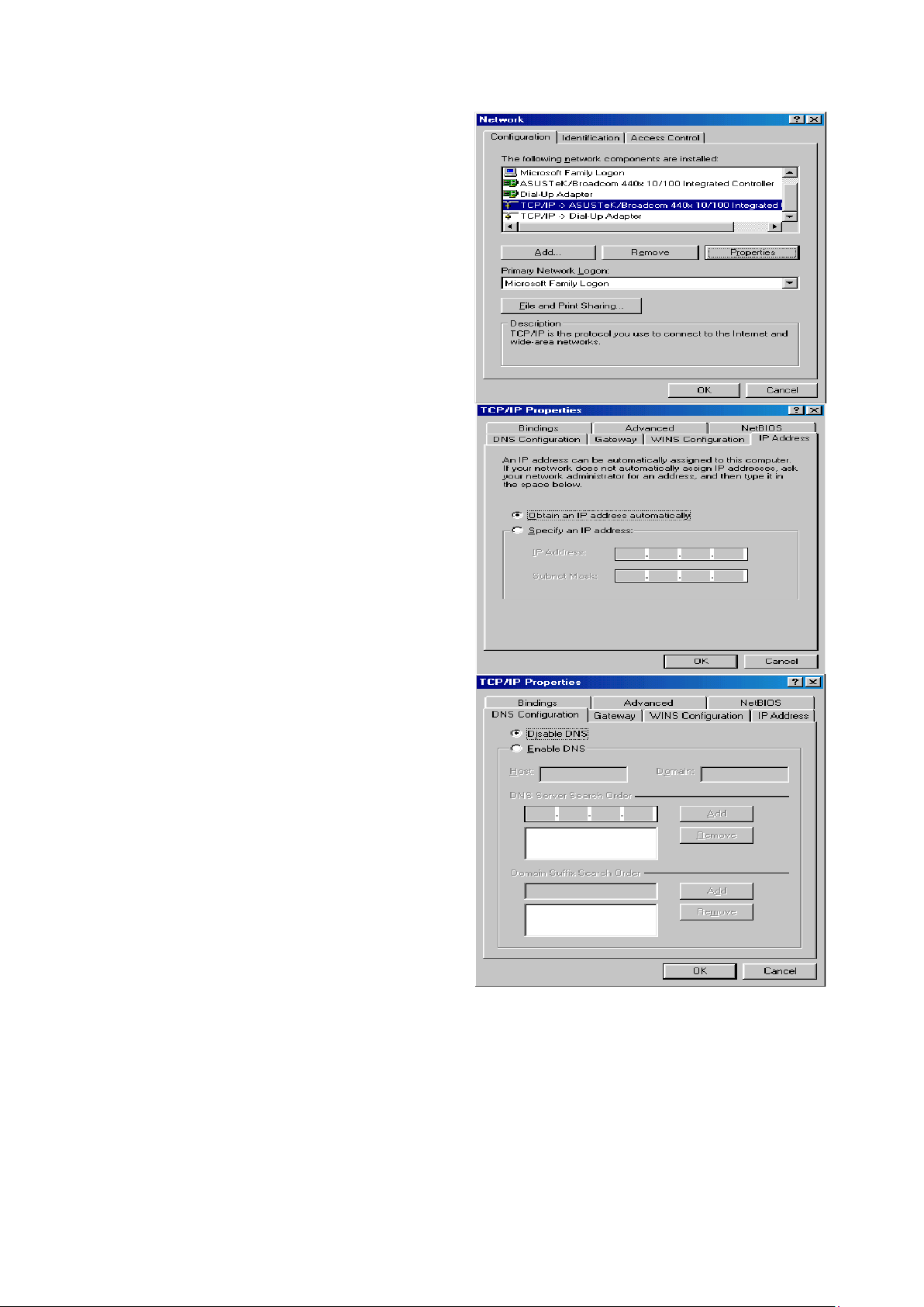
Conguring PC in Windows 95/98/Me
Go to Start > Settings > Control Panel. 1.
In the Control Panel, double-click on
Network and choose the Conguration
tab.
Select TCP/IP > NE2000 Compatible, 2.
or the name of your Network Interface
Card (NIC) in your PC.
Select the Obtain an IP address auto-3.
matically radio button.
Then select the DNS Congurationtab.4.
Select the Disable DNS radio button 5.
and click OK to nish the conguration.
15
Page 19
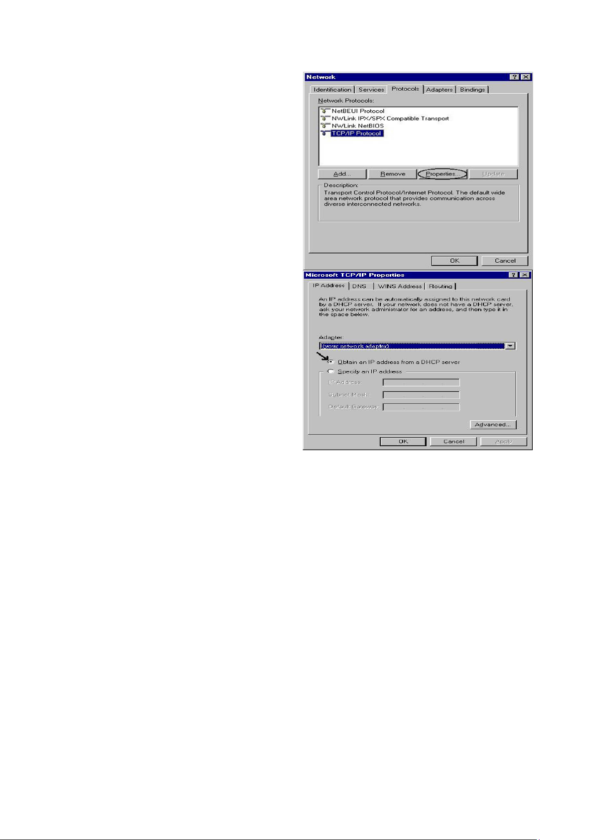
Conguring PC in Windows NT4.0
Go to Start > Settings > Control Panel. 1.
In the Control Panel, double-click on
Network and choose the Protocols tab.
Select TCP/IP Protocol and click Prop-2.
erties.
Select the Obtain an IP address from 3.
a DHCP server radio button and click
OK.
16
Page 20
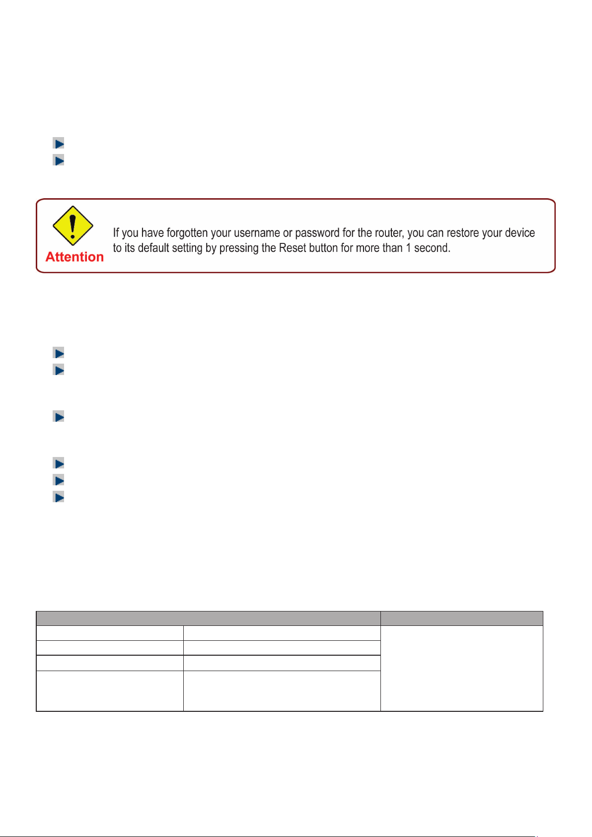
Factory Default Settings
Before conguring your router, you need to know the following default settings.
Web Interface (Username and Password)
Username: admin
Password: admin
The default username and password are “admin” and “admin” respectively.
Device LAN IP settings
IP Address: 192.168.1.254
Subnet Mask: 255.255.255.0
ISP setting in WAN site
PPPoE
DHCP server
DHCP server is enabled.
Start IP Address: 192.168.1.100
IP pool counts: 100
LAN and WAN Port Addresses
The parameters of LAN and WAN ports are pre-set in the factory. The default values are shown in
the tale.
LAN Port WAN Port
IP address 192.168.1.254
Subnet Mask 255.255.255.0
DHCP server function Enabled
IP addresses for
distribution to PCs
100 IP addresses continuing
from 192.168.1.100 through
192.168.1.199
The PPPoE function is
enabled to automatically get
the WAN port conguration
from the ISP.
17
Page 21

Information from your ISP
Before conguring this device, you have to check with your ISP (Internet Service Provider) to nd
out what kind of service is provided such as DHCP (Obtain an IP Address Automatically, Static IP
(Fixed IP Address) or PPPoE.
Gather the information as illustrated in the following table and keep it for reference.
VPI/VCI, VC / LLC-based multiplexing, Username, Password, Service
PPPoE(RFC2516)
PPPoA(RFC2684)
Name, and Domain Name System (DNS) IP address (it can be
automatically assigned by your ISP when you connect or be set manually).
VPI/VCI, VC / LLC-based multiplexing, Username, Password and
Domain Name System (DNS) IP address (it can be automatically
assigned by your ISP when you connect or be set manually).
MPoA(RFC1483/
RFC2684)
IPoA(RFC1577)
Pure Bridge VPI/VCI, VC / LLC-based multiplexing to use Bridged Mode.
VPI/VCI, VC / LLC-based multiplexing, IP address, Subnet mask,
Gateway address, and Domain Name System (DNS) IP address (it is a
xed IP address).
VPI/VCI, VC / LLC-based multiplexing, IP address, Subnet mask,
Gateway address, and Domain Name System (DNS) IP address (it is a
xed IP address).
18
Page 22
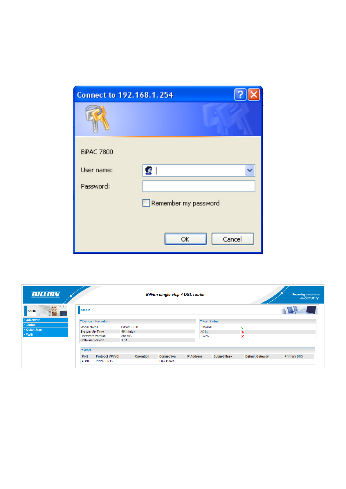
Chapter 4: Conguration
Open your web browser, enter the IP address of your router, which by default is 192.168.1.254, and
click “Go”, a login window prompt will appear. The default username and password are “admin” and
“admin” respectively.
Congratulations! You are now successfully logon to the BiPAC 7800 Firewall Router!
If the authentication succeeds, the homepage “Device Info - Summary” will appear on the screen.
19
Page 23

Quick Start
Step 1: Select WAN port connect mode from the connect mode drop down menu. There are two
types of connect mode to choose from: ADSL or EWAN
Step 2: After selecting the connect mode, press Continue to move on to the next conguring page.
There are 5 types of connection protocols available under ADSL connect mode while there are 2
types of connection protocols available for EWAN connect mode. Each type of connection mode
is described in the following sections of ADSL Connect mode and EWAN Connect mode.
Step 3: After nishing conguring the WAN connection, press Continue to nish the QuickStart. At
this time, you will see the system rebooting itself to apply the changes.
20
Page 24

ADSL Connect Mode
For ADSL connect mode there are 5 types of connection protocols: PPPoE, PPPoA, IPoA, MPoA
and Pure Bridge.
PPPoE
VPI/VCI: Enter the information provided by your ISP.
Username: Enter the username provided by your ISP. You can input up to 256 alphanumeric
characters (case sensitive). This is in the format of “username@ispname” instead of simply
“username”.
Password: Enter the password provided by your ISP. You can input up to 32 alphanumeric
characters (case sensitive).
Service Name: This item is for identication purposes. If it is required, your ISP will provide you
the necessary information. Maximum input is 32 alphanumeric characters.
Encapsulation mode: Select the encapsulation format. Select the one provided by your ISP.
Authentication method: Default is Auto. Please consult your ISP on whether to use Chap, Pap or
MSCHAP.
PPP IP Address: Your WAN IP address. Leave the IP address as 0.0.0.0 to enable the device to
automatically obtain an IP address from your ISP.
21
Page 25

PPPoA
VPI/VCI: Enter the information provided by your ISP.
Username: Enter the username provided by your ISP. You can input up to 256 alphanumeric
characters (case sensitive). This is in the format of “username@ispname” instead of simply
“username”.
Password: Enter the password provided by your ISP. You can input up to 32 alphanumeric
characters (case sensitive).
Service Name: This item is for identication purposes. If it is required, your ISP will provide you
the necessary information. Maximum input is 32 alphanumeric characters.
Encapsulation mode: Select the encapsulation format. Select the one provided by your ISP.
Authentication method: Default is Auto. Please consult your ISP on whether to use Chap, Pap or
MSCHAP.
PPP IP Address: Your WAN IP address. Leave the IP address as 0.0.0.0 to enable the device to
automatically obtain an IP address from your ISP.
22
Page 26

IPoA Connection
VPI/VCI: Enter the VPI and VCI information provided by your ISP.
Encapsulation mode: Select the encapsulation format. Select the one provided by your ISP.
IP Address: IPOA WAN IP address can only set x IP address.
Subnet mask: User can change it to others such as 255.255.255.128. Type the netmask assigned
to you by your ISP (if given).
Default Gateway: Enter the IP address of the default gateway.
23
Page 27

MPoA Connection
VPI/VCI: Enter the VPI and VCI information provided by your ISP.
Encapsulation mode: Select the encapsulation format. Select the one provided by your ISP.
IP Address: Your WAN IP address. Leave the IP address as 0.0.0.0 to enable the device to
automatically obtain an IP address from your ISP.
Subnet Mask: User can change it to others such as 255.255.255.128. Type the netmask assigned
to you by your ISP (if given).
Default Gateway: Enter the IP address of the default gateway.
Pure Bridge connection
VPI/VCI: Enter the VPI and VCI information provided by your ISP.
Encapsulation mode: Select the encapsulation format. Select the one provided by your ISP.
24
Page 28

EWAN Connect Mode
For EWAN connect mode there are 2 types of connection protocols: PPPoE and IPoW.
PPPoE connection
Username: Enter the username provided by your ISP. You can input up to 256 alphanumeric
characters (case sensitive). This is in the format of “username@ispname” instead of simply
“username”.
Password: Enter the password provided by your ISP. You can input up to 32 alphanumeric
characters (case sensitive).
Service Name: This item is for identication purposes. If it is required, your ISP will provide you
the necessary information. Maximum input is 32 alphanumeric characters.
Authentication method: Default is Auto. Please consult your ISP on whether to use Chap, Pap or
MSCHAP.
PPP IP Address: Your WAN IP address. Leave the IP address as 0.0.0.0 to enable the device to
automatically obtain an IP address from your ISP.
25
Page 29

IPoW connection
IP Address: Your WAN IP address. Leave the IP address as 0.0.0.0 to enable the device to
automatically obtain an IP address from your ISP.
Subnet Mask: User can change it to others such as 255.255.255.128. Type the netmask assigned
to you by your ISP (if given)
Default Gateway: Enter the IP address of the default gateway.
26
Page 30

Status (Basic Mode)
27
Page 31

Coguration (Basic Mode)
A WAN (Wide Area Network) is an outside connection to another network or the Internet. There
are two items within the WAN section: WAN Prole and ADSL Mode.
WAN – Main Port (ADSL)
PPPoE Connection (ADSL)
PPPoE (PPP over Ethernet) provides access control in a manner similar to dial-up services using
PPP.
VPI/VCI: Enter the information provided by your ISP.
Username: Enter the username provided by your ISP. You can input up to 256 alphanumeric
characters (case sensitive). This is in the format of “username@ispname” instead of simply
“username”.
Password: Enter the password provided by your ISP. You can input up to 32 alphanumeric
characters (case sensitive).
Service Name: This item is for identication purposes. If it is required, your ISP will provide you
the necessary information. Maximum input is 32 alphanumeric characters.
Encapsulation mode: Select the encapsulation format. Select the one provided by your ISP.
Auth. Protocol: Default is Auto. Please consult your ISP on whether to use Chap, Pap or
MSCHAP.
IP (0.0.0.0:Auto): Your WAN IP address. Leave this at 0.0.0.0 to obtain automatically an IP
address from your ISP.
28
Page 32

PPPoA Connection (ADSL)
PPPoA stands for Point to Point Protocol over ATM Adaptation Layer 5 (AAL5). It provides access
control and billing functionality in a manner similar to dial-up services using PPP.
VPI/VCI: Enter the information provided by your ISP.
Username: Enter the username provided by your ISP. You can input up to 256 alphanumeric
characters (case sensitive). This is in the format of “username@ispname” instead of simply
“username”.
Password: Enter the password provided by your ISP. You can input up to 32 alphanumeric
characters (case sensitive).
Service Name: This item is for identication purposes. If it is required, your ISP provides you the
information. Maximum input is 32 alphanumeric characters.
Encapsulation mode: Select the encapsulation format. Select the one provided by your ISP.
Auth. Protocol: Default is Auto. Please consult your ISP on whether to use Chap, Pap or
MSCHAP.
IP (0.0.0.0:Auto): Your WAN IP address. Leave the IP address as 0.0.0.0 to enable the device to
automatically obtain an IP address from your ISP.
29
Page 33

MPoA Connection (ADSL)
VPI/VCI: Enter the VPI and VCI information provided by your ISP.
Encap. mode: Select the encapsulation format. Select the one provided by your ISP.
IP Address: Your WAN IP address. Leave the IP address as 0.0.0.0 to enable the device to
automatically obtain an IP address from your ISP.
Subnet mask: User can change it to others such as 255.255.255.128. Type the netmask assigned
to you by your ISP (if given).
Default Gateway: Enter the IP address of the default gateway.
30
Page 34

IPoA Connections (ADSL)
VPI/VCI: Enter the VPI and VCI information provided by your ISP.
Encap. mode: Select the encapsulation format. Select the one provided by your ISP.
IP Address: Your WAN IP address. Leave the IP address as 0.0.0.0 to enable the device to
automatically obtain an IP address from your ISP.
Subnet mask: User can change it to others such as 255.255.255.128. Type the netmask assigned
to you by your ISP (if given).
Default Gateway: Enter the IP address of the default gateway.
31
Page 35

Pure Bridge Connections (ADSL)
VPI/VCI: Enter the VPI and VCI information provided by your ISP.
Encap. mode: Select the encapsulation format. Select the one provided by your ISP.
32
Page 36

WAN Prole – Main Port (EWAN)
Besides using ADSL to get connected to the Internet, Ethernet port 1 of BiPAC 7800 can be used
as an althernative to connect to Cable Modems, VDSL and ber optic lines. This alternative not
only provides faster connection to the Internet, it also provides users with more exibility to get
online.
PPPoE (EWAN)
Username: Enter the username provided by your ISP. You can input up to 256 alphanumeric
characters (case sensitive). This is in the format of “username@ispname” instead of simply
“username”.
Password: Enter the password provided by your ISP. You can input up to 32 alphanumeric
characters (case sensitive).
Service Name: This item is for identication purposes. If it is required, your ISP will provide you
the necessary information. Maximum input is 32 alphanumeric characters.
Authentication method: Default is Auto. Please consult your ISP on whether to use Chap, Pap or
MSCHAP.
PPP IP (0.0.0.0:Auto): Your WAN IP address. Leave the IP address as 0.0.0.0 to enable the
device to automatically obtain an IP address from your ISP.
33
Page 37

IPoW (IP over Ethernet)
IP Address: Your WAN IP address. Leave the IP address as 0.0.0.0 to enable the device to
automatically obtain an IP address from your ISP.
Subnet Mask: User can change it to others such as 255.255.255.128. Type the netmask assigned
to you by your ISP (if given).
Default Gateway: Enter the IP address of the default gateway.
34
Page 38

Status (Advanced Mode)
35
Page 39

ADSL
DSP Firmware Version: DSP code version.
DMT Status: Current DMT Status.
Operational Mode: Display the ADSL state when the connect mode is set to AUTO.
Upstream: Upstream rate.
Downstream: Downstream rate.
Noise Margin (Upstream): This shows the noise margin for upstream rate.
Noise Margin (Downstream): This shows the noise margin for downstream rate.
Attenuation (Upstream): This is attenuation of signal in upstream.
Attenuation (Downstream): This is attenuation of signal in downstream.
36
Page 40

ARP
This table shows the mapping of Internet (IP) addresses to Ethernet (MAC) addresses. This
is useful in determining the MAC address of the network interface of your PCs that use the
router’s Firewall – MAC Address Filter function. See the Firewall section of this manual for more
information on this feature.
IP Address: Shows the IP Address of internal host that join this network as well as the external IP.
MAC Address: The MAC address of internal host.
Interface: The interface name (on the router) that this IP address connects to.
DHCP
IP Address: The current corresponding DHCP-assigned dynamic IP address of the device.
MAC Address: The MAC Address of internal dhcp client host.
Client Host Name: The Host Name of internal dhcp client.
Expires In: Shows the expiry length of time.
37
Page 41

System Log
Display all the system logs that have been recorded up to the present time.
38
Page 42

Conguration (Advanced Mode)
LAN
A Local Area Network (LAN) is a shared communication system network where many computers
are connected. This type of network is area dened and is usually limited to a conned region
within a building or just within the same storey of a building. There are 3 items within the LAN
section: Ethernet, IP Alias and DHCP Server.
Ethernet
The router supports more than one Ethernet IP addresses in the LAN, and with distinct LAN
subnets through which you can access the Internet at the same time. Users usually only have one
subnet in their LAN. The default IP address for the router is 192.168.1.254.
IP Address: The default IP on this router.
Netmask: The default subnet mask on this router.
RIP: RIP v1, RIP v2, RIP v1+v2 and RIP v2 Multicast.
IP Alias
This function allows the addition of more than 1 IP address to the network interface. This further
allows user to assign each IP address with specied functions.
IP Address: Enter the IP address to be added to the network.
Netmask: Specify a subnet mask for the IP to be added.
39
Page 43

DHCP Server
DHCP allows networked devices to obtain information on the parameter of IP, Netmask, Gateway
as well as DNS through the Ethernet Address of the device. If you check the DHCP Relay you
must enter the IP address of the DHCP server that assigns an IP address to the DHCP client in the
LAN. Use this function only if advised to do so by your network administrator or ISP. Click Apply to
enable this function.
40
Page 44

WAN
A WAN (Wide Area Network) is a computer network that covers a broad geographical area (eg.
Internet) that is used to connect LAN and other types of network systems. There are two items
within the WAN section: WAN Prole and ADSL Mode.
WAN Prole (ADSL)
PPPoE Connection (ADSL)
PPPoE (PPP over Ethernet) provides access control in a manner similar to dial-up services using
PPP.
Description: A given name for the connection.
VPI/VCI: Enter the information provided by your ISP.
Encapsulation mode: Select the encapsulation format. Select the one provided by your ISP.
Username: Enter the username provided by your ISP. You can input up to 256 alphanumeric
characters (case sensitive). This is in the format of “username@ispname” instead of simply
“username”.
Password: Enter the password provided by your ISP. You can input up to 32 alphanumeric
characters (case sensitive).
Service Name: This item is for identication purposes. If it is required, your ISP will provide you
the necessary information. Maximum input is 32 alphanumeric characters.
NAT: The NAT (Network Address Translation) feature allows multiple users to access the Internet
through a single IP account by sharing a single IP address. If users on your LAN have their own
public IP addresses to access the Internet, NAT function can be disabled.
IP (0.0.0.0:Auto): Your WAN IP address. Leave the IP address as 0.0.0.0 to enable the device to
automatically obtain an IP address from your ISP.
Auth. Protocol: Default is Auto. Please consult your ISP on whether to use Chap, Pap or
MSCHAP.
41
Page 45

Connection:
Always on: If you want the router to establish a PPPoE session during start up and to auto-
matically re-establish the PPPoE session when disconnected by the ISP.
Idle Timeout: Auto-disconnect the broadband rewall gateway when there is no activity on the line
for a predetermined period of time.
MTU: Control the maximum Ethernet packet size your PC will send.
42
Page 46

PPPoA Connection (ADSL)
PPPoA stands for Point to Point Protocol over ATM Adaptation Layer 5 (AAL5). It provides access
control and billing functions in a manner similar to dial-up services using PPP.
Description: A given name for the connection.
VPI/VCI: Enter the information provided by your ISP.
Encapsulation mode: Select the encapsulation format. Select the one provided by your ISP.
Username: Enter the username provided by your ISP. You can input up to 256 alphanumeric
characters (case sensitive). This is in the format of “username@ispname” instead of simply
“username”.
Password: Enter the password provided by your ISP. You can input up to 32 alphanumeric
characters (case sensitive).
NAT: The NAT (Network Address Translation) feature allows multiple users to access the Internet
through a single IP account by sharing a single IP address. If users on your LAN have their own
public IP addresses to access the Internet, NAT function can be disabled.
IP (0.0.0.0:Auto): Your WAN IP address. Leave the IP address as 0.0.0.0 to enable the device to
automatically obtain an IP address from your ISP.
Auth. Protocol: Default is Auto. Please consult your ISP on whether to use Chap, Pap or
MSCHAP.
Connection:
Always on: If you want the router to establish a PPPoA session during start up and to auto-
matically re-establish the PPPoA session when disconnected by the ISP.
Idle Timeout: Auto-disconnect the broadband rewall gateway when there is no activity on the line
for a predetermined period of time.
MTU: Control the maximum Ethernet packet size your PC will send.
43
Page 47

MPoA Connection (ADSL)
Description: A user-denable name for this connection.
VPI/VCI: Enter the VPI and VCI information provided by your ISP.
Encap. mode: Select the encapsulation format. Select the one provided by your ISP.
NAT: The NAT (Network Address Translation) feature allows multiple users to access the Internet
through a single ISP account by sharing a single IP address. If users on your LAN have their own
public IP addresses to access the Internet, NAT function can be disabled.
IP Address: Your WAN IP address. Leave the IP address as 0.0.0.0 to enable the device to
automatically obtain an IP address from your ISP.
Netmask: User can change it to other such as 255.255.255.128. Type the netmask assigned to
you by your ISP (if given)
Gateway: Enter the IP address of the default gateway.
Obtain DNS Automatically: Select this check box to activate DNS.
Primary DNS/ Secondary DNS: Enter the IP addresses of the DNS servers. The DNS servers are
passed to the DHCP clients along with the IP address and the netmask.
44
Page 48

IPoA Connections (ADSL)
Description: A user-denable name for this connection.
VPI/VCI: Enter the VPI and VCI information provided by your ISP.
Encap. mode: Select the encapsulation format. Select the one provided by your ISP.
NAT: The NAT (Network Address Translation) feature allows multiple users to access the Internet
through a single ISP account by sharing a single IP address. If users on your LAN have their own
public IP addresses to access the Internet, NAT function can be disabled.
IP Address: Your WAN IP address. Leave the IP address as 0.0.0.0 to enable the device to
automatically obtain an IP address from your ISP.
Netmask: User can change it to other such as 255.255.255.128. Type the netmask assigned to
you by your ISP (if given)
Gateway: Enter the IP address of the default gateway.
Obtain DNS Automatically: Select this check box to activate DNS.
Primary DNS/ Secondary DNS: Enter the IP addresses of the DNS servers. The DNS servers are
passed to the DHCP clients along with the IP address and the netmask.
45
Page 49

Pure Bridge Connections (ADSL)
Description: A user-denable name for this connection.
VPI/VCI: Enter the VPI and VCI information provided by your ISP.
Encap. mode: Select the encapsulation format. Select the one provided by your ISP.
46
Page 50

WAN Prole – Main Port (EWAN)
Besides using ADSL to connect to the Internet, BiPAC 7800 Ethernet port 1 is also an alternative
to connect to Cable Modems, VDSL and ber optic lines. This alternative provides users with
faster connection & exibility to connect to the Internet.
PPPoE (EWAN)
Username: Enter the username provided by your ISP. You can input up to 256 alphanumeric
characters (case sensitive). This is in the format of “username@ispname” instead of simply
“username”.
Password: Enter the password provided by your ISP. You can input up to 32 alphanumeric
characters (case sensitive).
Service Name: This item is for identication purposes. If it is required, your ISP will provide you
the necessary information. Maximum input is 32 alphanumeric characters.
NAT: The NAT (Network Address Translation) feature allows multiple users to access the Internet
through a single IP account by sharing the single IP address. If users on your LAN have their own
public IP addresses to access the Internet, NAT function can be disabled.
IP (0.0.0.0:Auto): Your WAN IP address. Leave the IP address as 0.0.0.0 to enable the device to
automatically obtain an IP address from your ISP.
Auth. Protocol: Default is Auto. Please consult your ISP on whether to use Chap, Pap or
MSCHAP.
Connection:
Always on: If you want the router to establish a PPPoE session during start up and to auto-
matically re-establish the PPPoE session when disconnected by the ISP.
Idle Timeout: Auto-disconnect the broadband rewall gateway when there is no activity on the line
for a predetermined period of time.
MAC Spoong: This option is required by some service Providers. You must ll the MAC address
specied by your service provider when this information is required. The default setting is set to
disable.
47
Page 51

MTU: Control the maximum Ethernet packet size your PC will send.
IPoW (IP over Ethernet)
NAT: The NAT (Network Address Translation) feature allows multiple users to access the Internet
through a single ISP account by sharing a single IP address. If users on your LAN have their own
public IP addresses to access the Internet, NAT function can be disabled.
MAC Spoong: This option is required by some service Providers. You must ll the MAC address
specied by your service provider when this information is required. The default setting is set to
disable.
IP Address: Your WAN IP address. Leave the IP address as 0.0.0.0 to enable the device to
automatically obtain an IP address from your ISP.
Netmask: User can change it to other such as 255.255.255.128. Type the netmask assigned to
you by your ISP (if given).
Gateway: Enter the IP address of the default gateway.
Obtain DNS Automatically: Select this check box to activate DNS.
Primary DNS/ Secondary DNS: Enter the IP addresses of the DNS servers. The DNS servers are
passed to the DHCP clients along with the IP address and the netmask.
48
Page 52

ADSL Mode
ADSL Mode: There are 2 modes “Annex L” and ”Annex M” that user can select for this
connection.
Modulator: There are 5 modes “ADSL2”, ”ADSL2+”, “G.Lite:”, “T1.413” and “G.DMT” that user
can select for this connection.
49
Page 53

System
There are ve items within the System section: Time Zone, Firmware Upgrade, Backup/
Restore, Restart and User Management.
Time Zone
The router does not have a real time clock on board; instead, it uses the Simple Network Time
Protocol (SNTP) to get the most current time from an SNTP server outside your network. Choose
your local time zone from the drop down menu. To apply the selected local time zone, click Enable
and click the Apply button. After a successful connection to the Internet, the router will retrieve
the correct local time from the SNTP server you have specied. If you prefer to specify an SNTP
server other than those in the drop-down list, simply enter its IP address in their appropriate blanks
provided as shown above. Your ISP may also provide an SNTP server for you to use.
Firmware Upgrade
Your router’s “rmware” is the software that allows it to operate and provides all its functionality.
Think of your router as a dedicated computer, and the rmware as the software that runs in your
router. Thus, by upgrading the newly improved version of the rmware allows you the advantage to
use newly integrated features.
Click on Browse to select the new rmware image le you have downloaded to your PC. Once the
correct le is selected, click Upgrade to update the rmware to your router.
50
Page 54

Backup / Restore
These functions allow you to save a backup of the current conguration of your router to a dened
location on your PC, or to restore a previously saved conguration. This is useful if you wish to
experiment with different settings, knowing that you have a backup in hand in case any mistakes
occur. It is advisable that you backup your router conguration before making any changes to your
router conguration.
Press Backup Settings to select where on your local PC you want to store your setting le. You
may also want to change the name of the le when saving if you wish to keep multiple backups.
Press Browse… to select a le from your PC to restore. You should only restore your router setting
that has been generated by the Backup function which is created with the current version of the
router rmware. Settings les saved to your PC should not be manually edited in any way.
Select the settings les you wish to use, and press Update Settings to load the setting into the
router.
51
Page 55

Restart
There are 2 options for you to choose from before restarting the your 7800 device. You can
either choose to restart your device to restore it to the Factory Default Settings or to restart the
device with your current settings applied. Restarting your device to Factory Default Setting will be
useful especially after you have accidentally changed your settings that may result in undesirable
outcome.
After selecting the type of setting you want the device to restart with, click the Restart button to
initiate the process. After restarting, please wait several minutes to let the selected setting applied
to the system.
User Management
In order to prevent unauthorized access to your router conguration interface, it requires all users
to login with a username and password. Therefore only system administrator can access the
system. It is highly recommended that you change your password upon receiving your router. The
default password is “admin”.
To change your password, simply enter the old password in the Old Password blank. Then enter
your new password in the New Password and Conrm Password blanks provided. When this is
done, press Apply to save changes.
52
Page 56

Firewall
Packet Filter
Packet ltering enables you to congure your router to block specied internal/external users (IP
address) from Internet access, or you can disable specic service requests (Port number) to / from
the Internet. This conguration program allows you to set up different lter rules for different users
based on their IP addresses or their network Port number. The relationship among all lters is “or”
operation, which means that the router checks these different lter rules one by one, starting from
the rst rule. As long as one of the rules is satised, the specied action will be taken.
Rule Name: User dened description for entry identication. The maximum name length is 32
characters, and then can choose an application that they want from the listbox.
Source IP address / Source Subnet Mask: This is an Address-Filter used to allow or block trafc
to/from particular IP address(es). Enter the IP & subnet mask you want to lter. If you leave empty
or 0.0.0.0, it means any IP address.
Destination IP address / Destination Subnet Mask: This is an Address-Filter used to allow or
block trafc to/from particular IP address(es). Enter the IP & subnet mask you want to lter. If you
leave empty or 0.0.0.0, it means any IP address.
Source Port: This Port or Port Range denes the ports allowed by the Remote/WAN to connect to
the application. Default is set from range 0 ~ 65535. It is recommended that only advance user is
to congure this feature.
Destination Port: This is the Port or Port Range that denes the port of the application.
Protocol: Specify the packet type (TCP, UDP, TCP/UDP) that the rule applies to. Select TCP if
you wish to search for the connection-based application service on the remote server using the
port number. Or select UDP if you want to search for the connectionless application service on the
remote server using the port number.
Direction: Determine whether the rule is for outgoing packets or for incoming packets.
Add: Click this button to add a new packet lter rule and the added rule will appear at the bottom
table.
Edit: Check the Rule No. you wish to edit, and then click “Edit”.
Delete: Check the Rule No. you wish to delete, and then click “Delete”.
53
Page 57

MAC Filter
A MAC (Media Access Control) address is the unique network hardware identier for each PC on
your network’s interface (i.e. its Network Interface Card or Ethernet card). Using your router’s MAC
Address Filter function, you can congure the network to block specic machines from accessing
your LAN.
To lter a specic MAC address, enter the MAC address in the blank provided then press Add.
The format of MAC address-- could be: xx:xx:xx:xx:xx:xx or xx-xx-xx-xx-xx-xx
Block WAN Ping
This feature is to be enabled when you want the public WAN IP address on your 7800 device not
to respond to any ping command.
When activating Block WAN PING feature, check the Enable box then click the Apply button. This
feature is deactivated by default.
54
Page 58

Virtual Server
Virtual Server allows you to direct incoming trafc from WAN side (identied by Protocol and
External port) to the Internal server with private IP address on the LAN side. The Internal port is
required only if the external port needs to be converted to a different port number used by the
server on the LAN side.
In TCP and UDP networks a port is a 16-bit number used to identify which application program
(usually a server) incoming connections should be delivered to. Some ports have numbers that
are pre-assigned to them by the IANA (the Internet Assigned Numbers Authority), and these are
referred to as “well-known ports”. Servers follow the well-known port assignments so clients can
locate them.
If you wish to run a server on your network that can be accessed from the WAN (i.e. from other
machines on the Internet that are outside your local network), or any application that can accept
incoming connections (e.g. Peer-to-peer/P2P software such as instant messaging applications and
P2P le-sharing applications) and are using NAT (Network Address Translation), then you need to
congure your router to forward these incoming connection attempts using specic ports to the PC
on your network running the application. You also need to use port forwarding if you wish to host
an online game server.
Examples of well-known and registered port numbers are shown below, for further information,
please see IANA’s website at: http://www.iana.org/assignments/port-numbers
Well-known and Registered Ports
Port Number Protocol Description
20 TCP FTP Data
21 TCP FTP Control
22 TCP & UDP SSH Remote Login Protocol
23 TCP TElnet
25 TCP SMTP (simple Mail Transfer Protocol)
53 TCP & UDP DNS (Domain Name Server)
69 UDP TFTP (Trivial File Transfer Protocol)
80 TCP World Wide Web HTTP
110 TCP POP3 (Post Ofce Protocol version 3)
119 TCP NEWS (Network News Transfer Protocol)
123 UDP NTP (Network Time Protocol)
161 TCP SNMP
443 TCP & UDP HTTPS
1503 TCP T.120
1720 TCP H.323
4000 TCP ICQ
7070 UDP Real Audio
55
Page 59

Port Mapping
Application: Select the service you wish to congure.
Protocol: A protocol is automatically applied when an Application is selected from the listbox or
you may select a protocol type which you want.
External Port & Internal Port: Enter the public port number & range you wish to congure.
Internal IP Address: Enter the IP address of a specic internal server to which requests from the
specied port is forwarded.
Add: Click to add a new virtual server rule. Click again and the next gure appears.
Edit: Check the Edit radio button to display the parameter of the selected application, then after
changing the parameters click the Edit/Delete button to apply the changes.
Delete: To remove a port mapping application, check the Remove box of the selected application
then click the Edit/Delete button.
Since NAT acts as a “natural” Internet rewall, your router protects your network from accessed
by outside users, as all incoming connection attempts point to your router unless you specically
create Virtual Server entries to forward those ports to a PC on your network. When your router
needs to allow outside users to access internal servers, e.g. a web server, FTP server, Email
server or game server, the router can act as a “virtual server”. You can set up a local server with
a specic port number for the service to use, e.g. web/HTTP (port 80), FTP (port 21), Telnet (port
23), SMTP (port 25), or POP3 (port 110). When an incoming access request the router for a
specied port is received, it is forwarded to the corresponding internal server.
For example, if you set the port number 80 (Web/HTTP) to be mapped to the IP Address
192.168.1.2, then all incoming HTTP requests from outside users are forwarded to the local server
(PC) with the IP address of 192.168.1.2. If the port is not listed as a predened application, you
need to add it manually.
In addition to specifying the port number used, you also need to specify the protocol used. The
protocol is determined by a particular application. Most applications use TCP or UDP, however you
may also specify other protocols using the drop-down Protocol menu. Setting the protocol to “all”
causes all incoming connection attempts using all protocols on all port numbers to be forwarded to
the specied IP address.
56
Page 60

57
DMZ
The DMZ Host is a local computer exposed to the Internet. When setting a particular internal IP
address as the DMZ Host, all incoming packets that do not use a port number which is already
used by any other Virtual Server entries will rst be checked by the Firewall and NAT algorithms
before it is passed to the DMZ host.
Page 61

Advanced
Static Route
Enter the destination network address, subnet mask, gateway AND/OR the available WAN
interface, then click “Add” to add a new entry to the routing table.
Dynamic DNS
The Dynamic DNS function lets you alias a dynamic IP address to a static hostname, so if your
ISP does not assign you a static IP address you can still use a domain name. This is especially
useful for hosting servers via your ADSL connection, so that anyone wishing to connect to you
may use your domain name, rather than having to use your dynamic IP address, which changes
from time to time. This dynamic IP address is the WAN IP address of the router, which is assigned
to you by your ISP.
You rst need to register and establish an account with the Dynamic DNS provider using their
website, for example http://www.dyndns.org/
Dynamic DNS Server: Select the DDNS service you have established an account with.
Domain Name, Username and Password: Enter your registered domain name and your
username and password for this service.
Period: Enter the length of period in the blank, you can set the period unit in day (d), hour (H) or
month (M).
Wildcard: When enabled, you allow the system to lookup on domain names that do not exist to
have MX records synthesized for them.
58
Page 62

VLAN
VLAN (Virtual Local Area Network) is a group of devices on different physical LAN segments that
can communicate with each other as if they were all on the same physical LAN segment.
59
Page 63

Device Management
The Device Management advanced conguration settings allow you to control your router’s
security options and device monitoring features.
UPnP offers peer-to-peer network connectivity for PCs and other network devices, along with the
feature to control data transfer between devices. UPnP offers many advantages for users running
NAT routers through UPnP NAT Traversal, and on supported systems. By letting the application
control the required settings and removing the need for the user to control the advanced
conguration of their device will make tasks such as port forwarding become easier.
Both user’s Operating System and its relevant applications must support UPnP in addition to
the router. Windows XP and Windows Me have a native built-in support for UPnP (when the
component is installed). Windows 98 users may have to install the Internet Connection Sharing
client from Windows XP in order to support UpnP feature. Windows 2000 does not support UPnP.
60
Page 64

Installing UPnP in Windows Example
Follow the steps below to install the UPnP in Windows Me.
Step 1: Click Start and Control Panel. Double-click Add/Remove Programs.
Step 2: Click on the Windows Setup tab and select Communication in the Components selection
box. Click Details.
Step 3: In the Communications window, select the Universal Plug and Play check box in the
Components selection box.
61
Page 65

Step 4: Click OK to go back to the Add/Remove Programs Properties window. Click Next.
Step 5: Restart the computer when prompted.
Follow the steps below to install the UPnP in Windows XP.
Step 1: Click Start and Control Panel.
Step 2: Double-click Network Connections.
Step 3: In the Network Connections window, click Advanced in the main menu and select Optional
Networking Components ….
Step 4: When the Windows Optional Networking Components Wizard window appears, select
Networking Service in the Components selection box and click Details.
Step 5: In the Networking Services window, select the Universal Plug and Play check box.
Step 6: Click OK to go back to the Windows Optional Networking Component Wizard window and
click Next.
62
Page 66

Auto-discover Your UPnP-enabled Network Device
Step 1: Click start and Control Panel. Double-click Network Connections. An icon displays under
Internet Gateway.
Step 2: Right-click the icon and select Properties.
Step 3: In the Internet Connection Properties window, click Settings to see the port mappings that
were automatically created.
63
Page 67

Step 4: You may edit or delete the port mappings or click Add to manually add port mappings.
Step 5: Select Show icon in notication area when connected option and click OK. An icon
displays in the system tray.
Step 6: Double-click on the icon to display your current Internet connection status.
64
Page 68

Web Congurator Easy Access
With UPnP, you can access web-based conguration for the BiPAC 7800 without rst nding out
the IP address of the router. This helps if you do not know the router’s IP address.
Follow the steps below to access web conguration.
Step 1: Click Start and then Control Panel.
Step 2: Double-click Network Connections.
Step 3: Select My Network Places under Other Places.
Step 4: An icon describing each UPnP-enabled device shows under Local Network.
Step 5: Right-click on the icon of your BiPAC 7800 and select Invoke. The web conguration login
screen displays.
Step 6: Right-click on the icon of your BiPAC 7800 and select Properties. A properties window
displays basic information about the BiPAC 7800.
65
Page 69

IGMP
IGMP, known as Internet Group Management Protocol, is used to manage hosts from multicast
group.
IGMP Proxy: Accepting multicast packet. Default is set to Disable.
IGMP Snooping: Allowing switched Ethernet / Wireless to check and make correct forwarding
decisions. Default is set to Disable.
TR-069 Client
Please contact you ISP for the information of TR069.
66
Page 70

Remote Access
Remote Access Control: Select Enable to allow management access from remote side (mostly
from internet).
67
Page 71

Appendix: Product Support & Contact
If you come across any problems please contact the dealer from where you purchased your product.
Contact Billion
Worldwide:
http://www.billion.com
MAC OS is a registered Trademark of Apple Computer, Inc.
Windows 98, Windows NT, Windows 2000, Windows Me, Windows XP and Windows Vista are registered
Trademarks of Microsoft Corporation.
68
 Loading...