

Page 1

BiPAC 9300(V)NX
GPON (VoIP) Wireless-N Gateway
User Manual
Last Revised on July 2009
Page 2

Table of Contents
Chapter 1: Product ............................................................................ 1
Introduction to your Router .......................................................... 1
Mini IP-PBX for VoIP calls ...................................................................1
OMCI remote management .................................................................1
Optimal Wireless Speed and Coverage ..............................................2
Features ..................................................................................... 3
GPON Compliance ..............................................................................3
Network Protocols and Features .........................................................3
Firewall ................................................................................................4
Quality of Service Control ................................................................... 4
IPTV Applications ................................................................................4
Wireless LAN ......................................................................................4
VoIP ....................................................................................................4
Management .......................................................................................5
Hardware Specications ............................................................ 6
Physical Interface ...............................................................................6
Physical Specications........................................................................6
Operating Environment ............................................................... 6
Chapter 2: Installing the Router ....................................................... 7
Package Contents ....................................................................... 7
Device Description ......................................................................9
BiPAC 9300VN(X) ...............................................................................9
Front Panel LED ............................................................................................... 9
Rear Ports ...................................................................................................... 10
BiPAC 9300N(X) ............................................................................... 11
Front Panel LED ............................................................................................. 11
Rear Ports ...................................................................................................... 12
Cabling ...................................................................................... 14
Chapter 3: Basic Network Installation .......................................... 15
Applications of the device ......................................................... 16
Page 3

Hardware Installation ................................................................ 17
Power Connection .............................................................................17
GPON Connection ............................................................................ 17
LAN Connection ................................................................................18
Network Conguration ............................................................... 19
Conguring PC in Windows Vista...................................................... 19
Conguring PC in Windows XP .........................................................21
Conguring PC in Windows 2000 ..................................................... 22
Conguring PC in Windows 95/98/Me............................................... 23
Conguring PC in Windows NT4.0 ....................................................24
Factory Default Settings ............................................................ 25
Easy Internet Access Conguration .......................................... 26
Conguring with your Web Browser ..................................................26
Chapter 4: Conguration ................................................................ 27
Quick Start ................................................................................28
Basic Conguration Mode ......................................................... 30
Status ................................................................................................30
WAN ..................................................................................................32
PPPoE ............................................................................................................ 32
DHCP Client ................................................................................................... 33
Static IP .......................................................................................................... 34
Pure Bridge..................................................................................................... 35
WLAN ................................................................................................36
Quick VoIP (Only for 9300VN(X)) ......................................................38
Advanced Conguration Mode .................................................. 40
Status ................................................................................................40
GPON Status .................................................................................................. 42
ARP Table ....................................................................................................... 43
DHCP Table ................................................................................................... 44
System Log..................................................................................................... 45
Firewall Log .................................................................................................... 46
VoIP CDR Log (Only for 9300VN(X)) .............................................................. 47
Page 4

SIP Accounts Status (ITSP) (Only for 9300VN(X)) ......................................... 48
SIP Extensions Status (Only for 9300VN(X)).................................................. 49
VoIP Call Status (Only for 9300VN(X)) ........................................................... 50
UPnP Portmap ................................................................................................ 51
Conguration .....................................................................................52
LAN - Local Area Network .............................................................................. 53
WAN - Wide Area Network ............................................................................. 72
System ........................................................................................................... 77
Firewall ........................................................................................................... 84
QoS - Quality of Service ................................................................................. 93
Virtual Server .................................................................................................. 98
Time Schedule .............................................................................................. 102
Advanced...................................................................................................... 103
Advanced VoIP (Only for 9300VN(X)) ............................................. 117
Extensions .................................................................................................... 118
SIP Accounts (ITSP) ..................................................................................... 120
Mini IP-PBX .................................................................................................. 123
Save Conguration to Flash .................................................... 129
Restart .................................................................................... 130
Logout ..................................................................................... 131
Chapter 5: Troubleshooting .......................................................... 132
Appendix: Product Support & Contact ........................................ 134
Page 5

Chapter 1: Product
Introduction to your Router
Thank you for purchasing BiPAC 9300(V)NX Wireless-N Gateway Router. Your new router is
a next-generation Gigabit Passive Optical Network (GPON) integrated access device (IAD). It
uses BroadLight’s BL2348 embedded System-on-Chip solution and is tted with a 4-port Gigabit
Ethernet Switch and Wi-Fi 802.11n access point.
BiPAC 9300(V)NX is a cost-effective solution for point-to-multipoint; ber-to-the-premises
network architecture in which passive optical splitters are used to allow a single optical ber to
serve multiple premises. Compliant with the ITU-T G.984 GPON standards, the device supports
maximum downstream rates up to 2.5Gbps and upstream rates up to 1.25Gbps. With this
technology, users can enjoy high-speed GPON services and bandwidth-consuming multimedia
applications such as interactive gaming, video streaming and real-time audio much easier and
faster than ever before.
BiPAC 9300(V)NX also has two RJ-11 FXS ports for connecting to regular telephones, allowing
users to make economical VoIP calls.
BiPAC 9300(V)NX supports the ONT Management and Control Interface (OMCI), which ensures
that Billion’s GPON ONT router is easy to congure, activate and manage remotely from a Optical
Line Terminal (OLT). By reducing call-outs, deployment and support costs of the ONT device are
greatly reduced.
Mini IP-PBX for VoIP calls
BiPAC 9300VNX Series is compliant with SIP standard (RFC3261) and supports SIP registrar.
The unique feature of the gateway is that it can be used as a mini IP-PBX that supports up to 20
user accounts for SIP extensions and 2 SIP accounts for making economical VoIP calls provided
by Internet Telephony Service Providers (ITSP). This router series integrates two FXS ports
allowing users to make or receive phone calls over the Internet simply by connecting the device
to their existing telephone set. This state-of-the-art feature is ideal for SOHO users, delivering
free communication between branch ofces and client sites. Making VoIP calls is just as easy as
dialing an extension number!
OMCI remote management
In order to meet the ITU-T G.984.4 requirements for OMCI (ONT Management Control Interface),
and dened compatibility and message transfer between OLT and ONT, and Management
Information Base (MIB) physical device management, BiPAC 9300VNX Series uses OpenCon’s
OMCI management. This tool is eld-proven and interoperable with other GPON Systems with
OMCI capabilities for both OLT and ONT equipment. OpenCon’s OMCI management has been
thoroughly tested to consistently meet ITU-T G.984.4 and is approved by the Full Service Access
Network (FSAN) Group.
1
Page 6

Optimal Wireless Speed and Coverage
With an integrated 802.11n Wireless Access Point, the router delivers up to 6 times the speed
and 3 times the wireless coverage of an 802.11b / g network device. It supports a link rate up
to 300Mbps and is also compatible with 802.11b/g equipment. The Wireless Protected Access
(WPA-PSK/WPA2-PSK) and Wireless Encryption Protocol (WEP) features enhance the level of
transmission security and access control over Wireless LAN. The router also supports the Wi-Fi
Protected Setup (WPS) standard, allowing users to establish a secure wireless network by simply
pushing a button. If the user’s network requires wider coverage, the built-in Wireless Distribution
System (WDS) repeater function expands the wireless network without needing any external wires
or cables.
2
Page 7

Features
• ITU-T G.984 GPON compliant
• Supports bandwidth maximum downstream rates up to 2.5Gbps and upstream rates up to
1.25Gbps
• Supports transmission distance up to 20km
• Dual-wavelength: Tx at 1310nm and Rx at 1490nm
• Supports OMCI (ONT Management and Control Interface) remote management
• Voice over IP compliant with SIP standards
• Two FXS ports for connecting to regular telephones
• Supports FAX Transmission: T.38 fax relay, G.711 pass-through
• Supports mini-IP PBX Features
• Draft 802.11n wireless and delivers up to 300Mbps link rate
• 802.11n Wireless AP with WPA-PSK/WPA2-PSK Supported
• Supports Wi-Fi WMM prioritization
• SOHO Firewall Security with DoS Prevention and SPI
• Quality of Service for trafc prioritization and bandwidth management
• Supports IPTV Applications
• Easy Sign-On (EZSO)
• Ideal for Home, SOHO and Ofce users
GPON Compliance
• GPON Compliance
• Compliant with ITU-T G.984 GPON standards
• G.984.1 General characteristics
• G.984.2 Physical Media Dependent (PMD) layer specications
• G.984.3 Transmission convergence layer specications
• G.984.4 Management and control interface
Network Protocols and Features
• NAT, static routing and RIP-1 / 2
• Universal Plug and Play (UPnP) compliant
• Dynamic Domain Name System (DDNS)
3
Page 8

• Virtual Server and DMZ
• SNTP, DNS relay and IGMP proxy
Firewall
• Stateful Packet Inspection (SPI)
• DoS attack prevention including IP Spoong, Land Attack, Smurf Attack, Ping of Death, TCP
SYN Flooding, etc.
• Packet Filtering - port, source IP address, destination IP address, MAC address
• URL Content Filtering - string or domain name detection in URL string
Quality of Service Control
• Supports the DiffServ approach
• Trafc prioritization and bandwidth management based-on IP protocol, port number and
address
IPTV Applications
IPTV application may require subscription to IPTV services from a Telco / ISP.
• IGMP proxy and snooping for video service
• Virtual LAN (VLAN)
• Quality of Service (QoS)
Wireless LAN
• Compliant with IEEE 802.11n draft 2.0, 802.11g and 802.11b standards
• 2.4GHz - 2.484GHz frequency range
• Up to 300Mbps wireless operation rate
• Wi-Fi Protected Setup (WPS) for easy setup
• 64- / 128-bit WEP supported for encryption
• Wireless Security with WPA-PSK / WPA2-PSK support
• WDS repeater function support
VoIP
• Two RJ-11 FXS ports for connecting to regular telephones
• Supports two SIP accounts for connecting to Internet Telephony Service Provider (ITSP)
• Supports SIP extensions
• Supports G.711 A/μ law, and G.729 Audio CODEC standards
4
Page 9

• Supports FAX Transmission: T.38 fax relay, G.711 pass-through
• Supports Telephony Features: silence suppression, Voice Activity Detection (VAD), Comfort
Noise Generation (CNG), G.168 echo cancellation, packet loss concealment
• Supports mini-IP PBX Features: Call Waiting, Call Transfer, Call Hold, Call Forward, Speed
Dial, Direct Inward Dialing (DID), Do Not Disturb (DND), Caller ID, Call Detail Record, Call
blocking (future release), 3-way conference (future release), Meeting Room (future release)
• Adaptive jitter buffer support
• DTMF: In-band/out-of-band (RFC2833) / SIP INFO
Management
• Quick Installation Wizard and Auto-scan for GPON settings
• Web-based GUI for remote and local management
• Firmware upgrades and conguration data upload and download via web-based GUI
• Embedded Telnet server for remote and local management
• SNMP v3, MIB-I and MIB-II support
• Supports DHCP server / client / relay
• OMCI supports remote management
• TR-069
5
Page 10

Hardware Specications
Physical Interface
• WLAN: detachable antenna
• WAN: SC/APC GPON port
• Telephone: 2-port FXS
• LAN: 4-port Gigabit auto-crossover (MDI/MDI-X) Switch
• USB 2.0 host port (BiPAC 9300VNX only)
• Factory default reset button
• WPS button
• Power jack
• Power switch
Physical Specications
• Dimensions: 9.04” x 6.10” x 1.69” (229.5 x 155 x 43mm)
• Power Requirements: Input: 15V DC, 1.6A
Operating Environment
Operating temperature: 0 – 40°C
Storage temperature: -20 – 70°C
Humidity: 20 – 95% non-condensing
6
Page 11
Chapter 2: Installing the Router
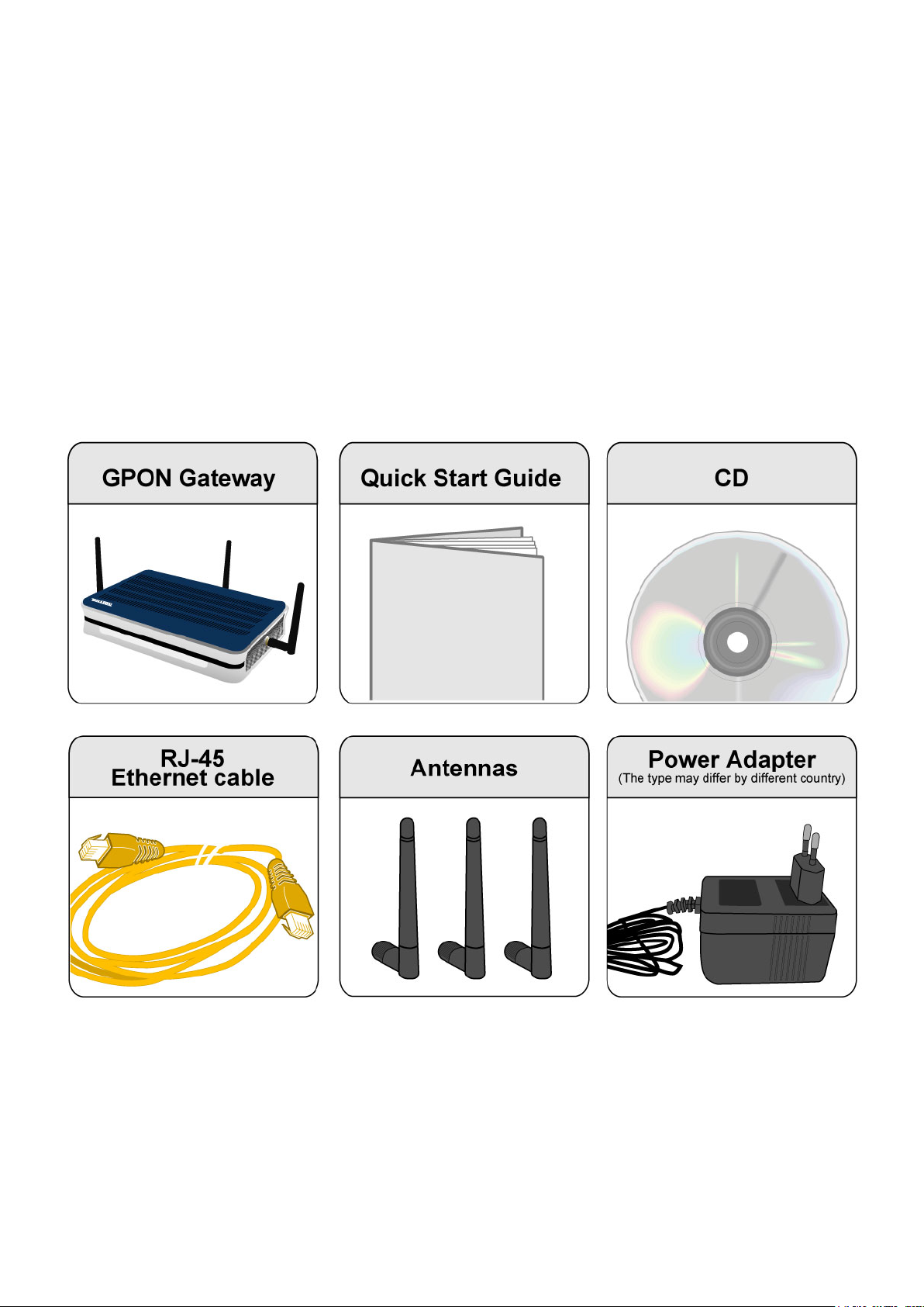
Package Contents
BiPAC 9300(V)NX GPON (VoIP) Wireless-N Gateway Router
CD containing the online manual
Ethernet (RJ-45) cable
Three 2dBi detachable antennas
Power adapter
Quick Start Guide
7
Page 12

Important note for using this router
8
Page 13

Device Description
BiPAC 9300VN(X)
Front Panel LED
LED Meaning
Lit red when the device is booting.
1 Power
Ethernet Port
2
3 Wireless
4 WPS
5
1X — 4X
(RJ-45 connector)
Phone
(RJ-11 connector)
Lit green when the system is ready.
Blinking when the device is rebooting or rmware is upgrading.
Lit green when one of the LAN ports is connected to an ofce/
home network of 1Gbps. Blinking when data is transmitted/
received.
Lit orange when one of the LAN ports is connected to an ofce/
home network of 10/100Mbps. Blinking when data is transmitted/
received.
Lit green when a wireless connection is established.
Blinking when data is transmitted/received.
Blinking when WPS is in progress.
Lit up brightly and then lit off within 5 seconds when WPS ends.
Lit green when phone is off hook.
6
VoIP
(RJ-11 connector)
7 GPON
8 Internet
After SIP registration is OK, the LED will lit green whenever the
phone is off hook.
Lit green when GPON is operational.
Lit off when ber is disconnected or GPON is not operational.
Lit red when WAN port fails to get IP address.
Lit green when WAN port gets IP address successfully.
Lit off when the device is in bridge mode or when WAN connection
is absent.
9
Page 14
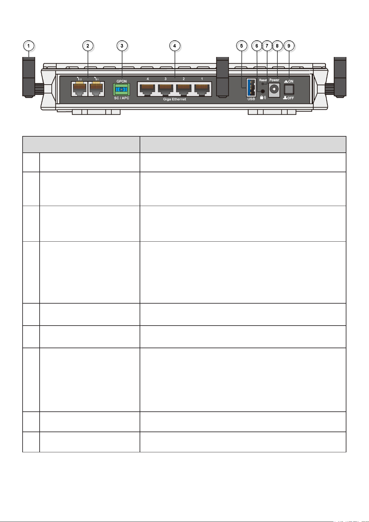
Rear Ports
Port Meaning
1 Antenna Connect the detachable antenna to this port.
Phone
2
1X- 2X
(RJ-11 connector)
Connect this port to an analog phone set with RJ-11 cable.
GPON
3
SC / APC
(SC/APC connector)
Giga Ethernet
4
1X - 4X
(RJ-45 connector)
5 USB Connect the USB cable to this port (BiPAC 9300VNX only).
6 WPS Push this button to trigger Wi-Fi Protected Setup function.
7 Reset
Connect the SMF ber cable to the GPON SC/APC port.
Connect a UTP Ethernet cable (Cat-5e or smaller) to one of
the LAN ports when connecting to a PC or an ofce/home
network of 10/100Mbps.
Connect a UTP Ethernet cable (Cat-5e or larger) to one of
the LAN ports when connecting to a PC or an ofce/home
network of 1Gbps.
Press this button for 6 seconds at least to reset device to
restore the device to factory default settings.
Note: Be sure that the device is being turned on when
press Reset button.
(If you cannot login to the router or forget your Username/
Password, press this button for more than 6 seconds).
8 Power Connect it with the supplied power adapter.
9 Power Switch Power ON/OFF switch.
10
Page 15

BiPAC 9300N(X)
Front Panel LED
LED Meaning
Lit red when the device is booting.
1 Power
Ethernet Port
2
3 Wireless
4 WPS
5 GPON
1X — 4X
(RJ-45 connector)
Lit green when the system is ready.
Blinking when the device is rebooting or rmware is upgrading.
Lit green when one of the LAN ports is connected to an ofce/
home network of 1Gbps. Blinking when data is transmitted/
received.
Lit orange when one of the LAN ports is connected to an ofce/
home network of 10/100Mbps. Blinking when data is transmitted/
received.
Lit green when a wireless connection is established.
Blinking when data is transmitted/received.
Blinking when WPS is in progress.
Lit up brightly and then lit off within 5 seconds when WPS ends.
Lit green when GPON is operational.
Lit off when ber is disconnected or GPON is not operational.
6 Internet
Lit red when WAN port fails to get IP address.
Lit green when WAN port gets IP address successfully.
Lit off when the device is in bridge mode or when WAN connection
is absent.
11
Page 16
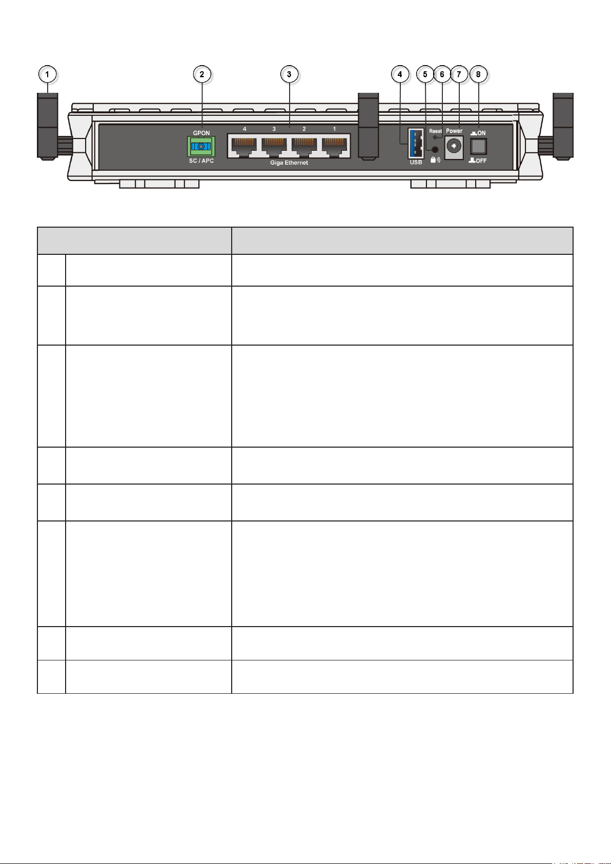
Rear Ports
Port Meaning
1 Antenna Connect the detachable antenna to this port.
GPON
2
SC / APC
(SC/APC connector)
Connect the SMF ber cable to the GPON SC/APC port.
Connect a UTP Ethernet cable (Cat-5e or smaller) to one of
Giga Ethernet
3
1X - 4X
(RJ-45 connector)
4 USB Connect the USB cable to this port (BiPAC 9300NX only).
5 WPS Push this button to trigger Wi-Fi Protected Setup function.
6 Reset
7 Power Connect it with the supplied power adapter.
the LAN ports when connecting to a PC or an ofce/home
network of 10/100Mbps.
Connect a UTP Ethernet cable (Cat-5e or larger) to one of
the LAN ports when connecting to a PC or an ofce/home
network of 1Gbps.
Press this button for 6 seconds at least to reset device to
restore the device to factory default settings.
Note: Be sure that the device is being turned on when
press Reset button.
(If you cannot login to the router or forget your Username/
Password, press this button for more than 6 seconds).
8 Power Switch Power ON/OFF switch.
12
Page 17

Recovery Operation
1. Recovery procedures for non-working routers (e.g. after a failed rmware upgrade ash):
The system will check the rmware of this device automatically while turning on the modem. Once
the rmware is not integrated, the system enters the recovery state. The modem emergency-reash
web interface will then be accessible via http://192.168.1.254 where you can upload a rmware
image to restore the modem to a functional state. Please note that the modem will only respond
via its web interface at this address, and will not respond to ping requests from your PC or to telnet
connections.
2. Recovery procedures for a lost web interface password:
After turning the router on, please press the Reset Button on the back of the modem, and hold
the button until all the lights on the modem begin to ash and then it will reboot itself to restore the
factory default settings. The login username and password will then be reset to admin. You can then
access its GUI via its default IP address at http://192.168.1.254/.
13
Page 18

Cabling
One of the most common causes of problem is bad cabling or GPON line(s). Make sure that all
connected devices are turned on. On the front panel of your router is a bank of LEDs. Verify that the
LAN Link and GPON line LEDs are lit. If they are not, verify if you are using the proper cables.
Fiber cable is very fragile, please be careful not to snap the cable when you use it. In order to
avoid dust entering, please put a lid on the head-end of the ber cable when not in use. If you
still have problem, please contact your ISP and tell them the serial number of this device (can be
found on the Status page).
14
Page 19

Chapter 3: Basic Network Installation
The router can be congured through your web browser. A web browser is included as a standard
application in the following operating systems: Linux, Mac OS, Windows 98/NT/2000/XP/Me/Vista,
etc. The product provides an easy and user-friendly interface for conguration.
Please check your PC network components. The TCP/IP protocol stack and Ethernet network
adapter must be installed. If not, please refer to your Windows-related or other operating system
manuals.
There are ways to connect the router, either through an external repeater hub or connect directly
to your PCs. However, make sure that your PCs have an Ethernet interface installed properly prior
to connecting the router device. You ought to congure your PCs to obtain an IP address through
a DHCP server or a xed IP address that must be in the same subnet as the router. The default IP
address of the router is 192.168.1.254 and the subnet mask is 255.255.255.0 (i.e. any attached PC
must be in the same subnet, and have an IP address in the range of 192.168.1.1 to 192.168.1.253).
The best and easiest way is to congure the PC to get an IP address automatically from the router
using DHCP. If you encounter any problem accessing the router web interface it is advisable to
uninstall your rewall program on your PCs, as they can cause problems accessing the IP address
of the router. Users should make their own decisions on what is best to protect their network.
Please follow the following steps to congure your PC network environment.
15
Page 20

Applications of the device
BiPAC 9300VN(X)
BiPAC 9300N(X)
16
Page 21
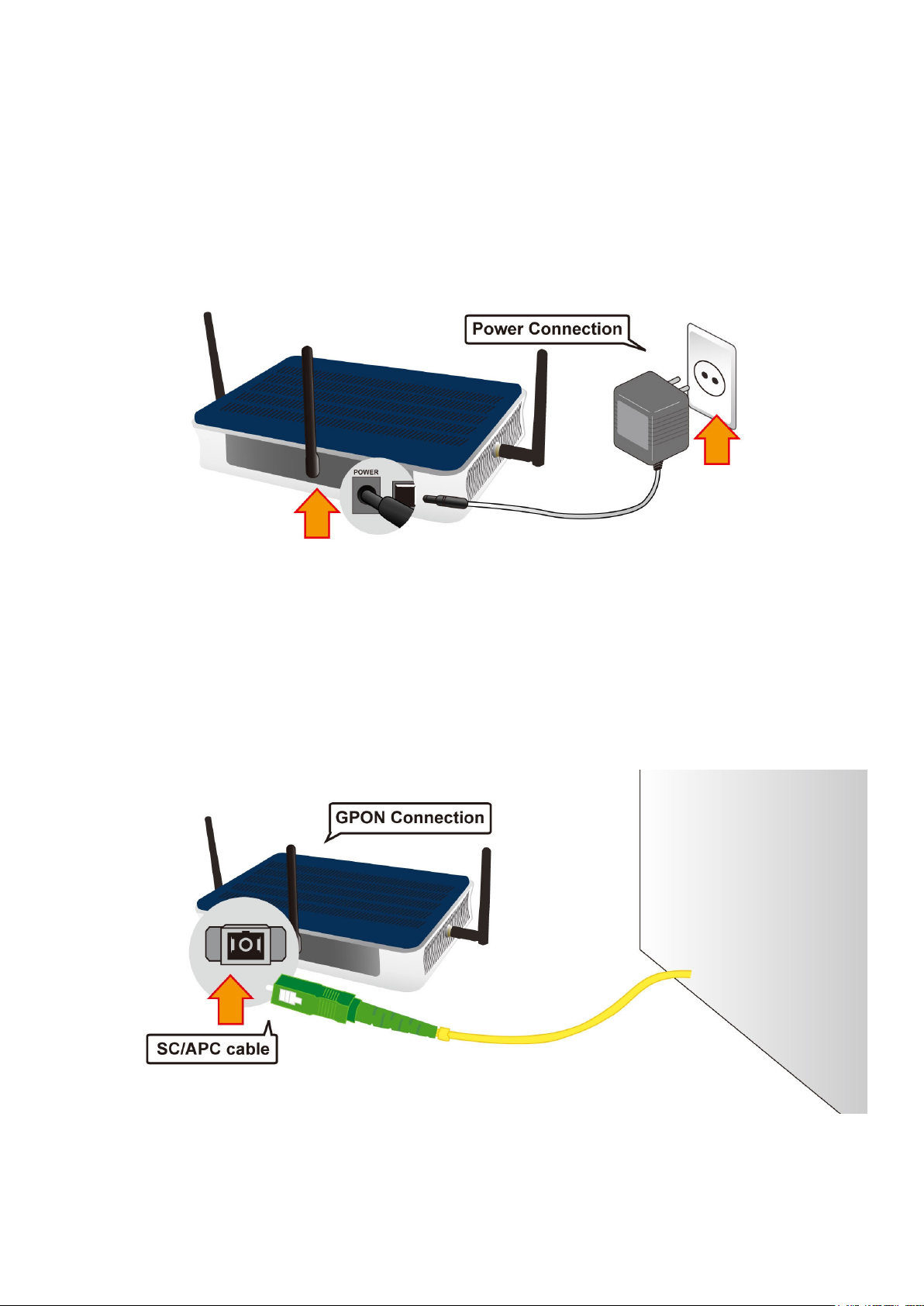
Hardware Installation
It is easy to connect BiPAC 9300(V)NX simply by performing the following instructions:
Power Connection
Plug one side of the supplied power adapter into the wall jack and connect the other side to the
gateway.
Note: The plug type may vary from country to country.
GPON Connection
Connect the supplied SC/APC cable to the gateway’s GPON port.
17
Page 22

LAN Connection
Connect one side of the supplied RJ-45 Ethernet cable to one of the Giga Ethernet ports, and the
other side to other Ethernet interface.
18
Page 23
Network Conguration
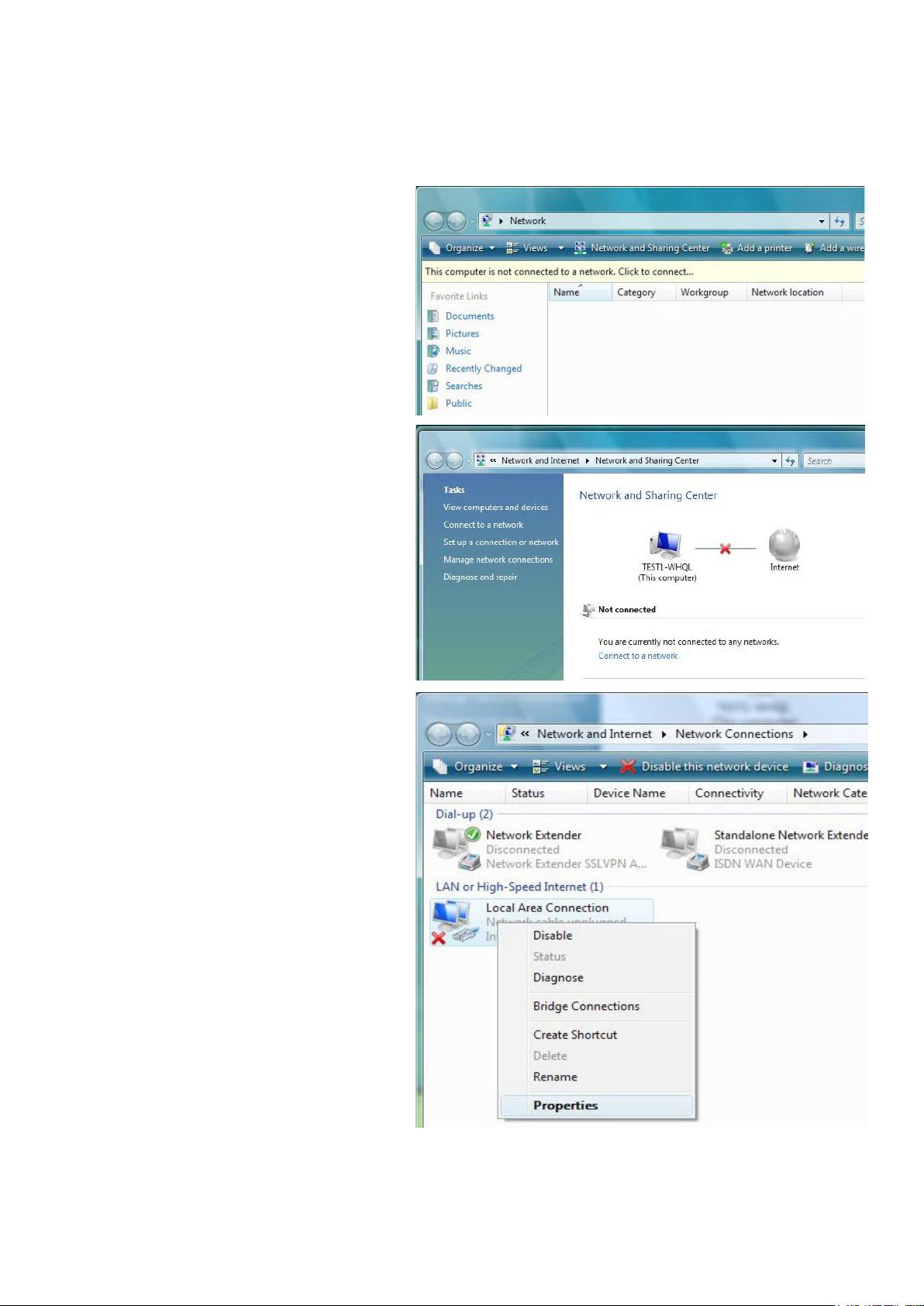
Conguring PC in Windows Vista
1. Go to Start. Click on Network.
2. Then click on Network and Sharing
Center at the top bar.
3. When the Network and Sharing
Center window pops up, select
and click on Manage network
connections on the left window
column.
4. Select the Local Area Connection,
and right click the icon to select
Properties.
19
Page 24
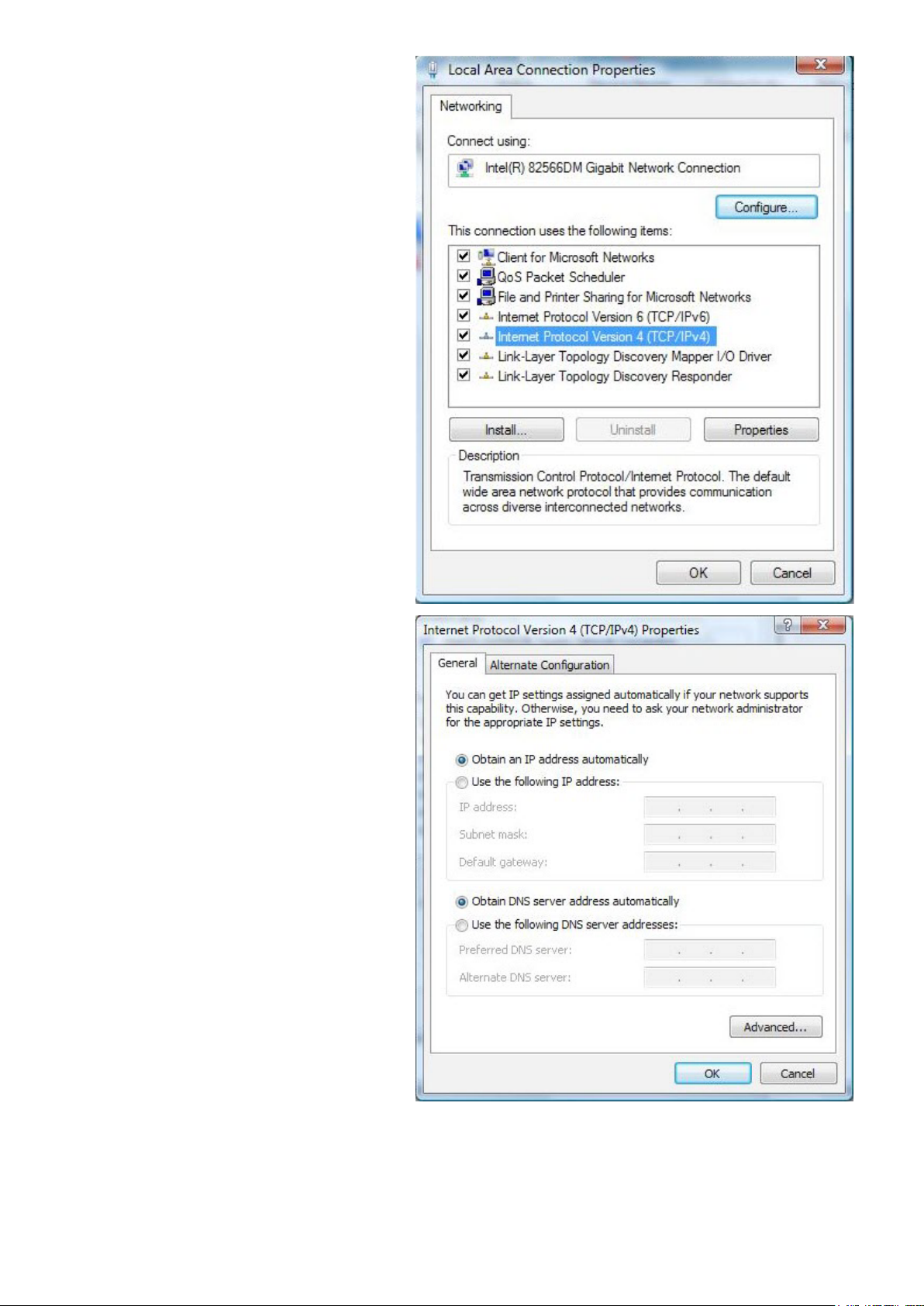
5. Select Internet Protocol Version 4
(TCP/IPv4) then click Properties.
6. In the TCP/IPv4 properties window,
select the Obtain an IP address
automatically and Obtain DNS
Server address automatically radio
buttons. Then click OK to exit the
setting.
7. Click OK again in the Local Area
Connection Properties window to
apply the new conguration.
20
Page 25
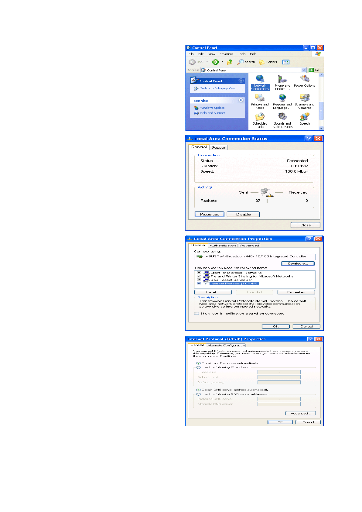
Conguring PC in Windows XP
1. Go to Start > Control Panel (in Classic
View). In the Control Panel, double-click
on Network Connections
2. Double-click Local Area Connection.
3. In the Local Area Connection Status
window, click Properties.
4. Select Internet Protocol (TCP/IP) and
click Properties.
5. Select the Obtain an IP address automatically and the Obtain DNS server
address automatically radio buttons.
6. Click OK to nish the conguration.
21
Page 26
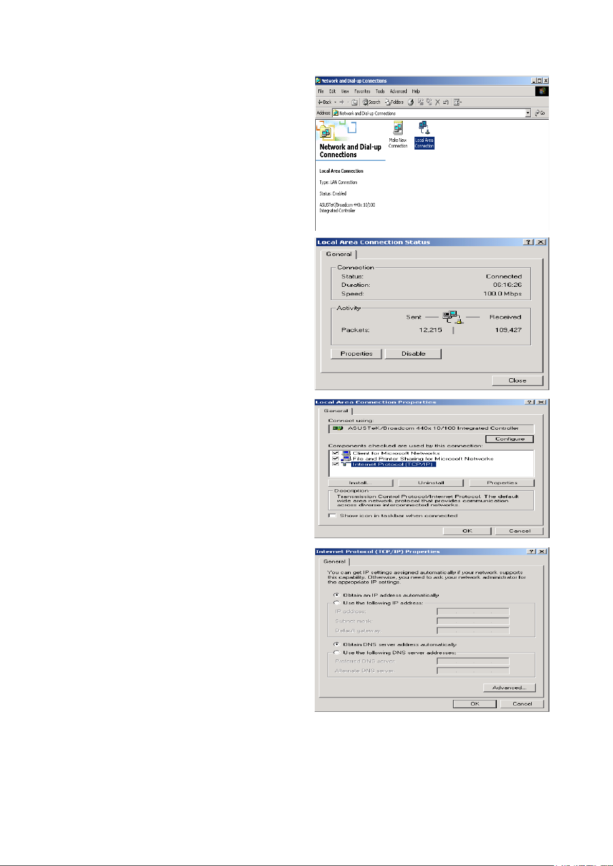
Conguring PC in Windows 2000
1. Go to Start > Settings > Control Panel.
In the Control Panel, double-click on
Network and Dial-up Connections.
2. Double-click Local Area Connection.
3. In the Local Area Connection Status
window click Properties.
4. Select Internet Protocol (TCP/IP) and
click Properties.
5. Select the Obtain an IP address automatically and the Obtain DNS server
address automatically radio buttons.
6. Click OK to nish the conguration.
22
Page 27

Conguring PC in Windows 95/98/Me
1. Go to Start > Settings > Control Panel.
In the Control Panel, double-click on
Network and choose the Conguration
tab.
2. Select TCP/IP > NE2000 Compatible,
or the name of your Network Interface
Card (NIC) in your PC.
3. Select the Obtain an IP address automatically radio button.
4. Then select the DNS Conguration tab.
5. Select the Disable DNS radio button
and click OK to nish the conguration.
23
Page 28

Conguring PC in Windows NT4.0
1. Go to Start > Settings > Control Panel.
In the Control Panel, double-click on
Network and choose the Protocols tab.
2. Select TCP/IP Protocol and click Properties.
3. Select the Obtain an IP address from
a DHCP server radio button and click
OK.
24
Page 29
Factory Default Settings
Before conguring your router, you need to know the following default settings.
Web Interface (Username and Password)
Username: admin
Password: admin
The default username and password are “admin” and “admin” respectively.
Device LAN IP settings
IP Address: 192.168.1.254
Subnet Mask: 255.255.255.0
ISP setting in WAN site
PPPoE
DHCP server
DHCP server is enabled.
Start IP Address: 192.168.1.100
IP pool counts: 100
LAN and WAN Port Addresses
The parameters of LAN and WAN ports are pre-set in the factory. The default values are shown in
the tale.
LAN Port WAN Port
IP address 192.168.1.254
Subnet Mask 255.255.255.0
DHCP server function Enabled
IP addresses for distribution to PCs
100 IP addresses continuing
from 192.168.1.100 through
192.168.1.199
The PPPoE function is
enabled to automatically get
the WAN port conguration
from the ISP. However, you
have to set the username
and password rst.
25
Page 30
Easy Internet Access Conguration
To easily congure this device for internet access, you must have IE 5.0 / Netscape 4.5 or above
installed on your computer. There is basically one way to congure your router before you are able
to connect to the internet: Web Interface. Conguration of this method will be discussed in detail
in the following section.
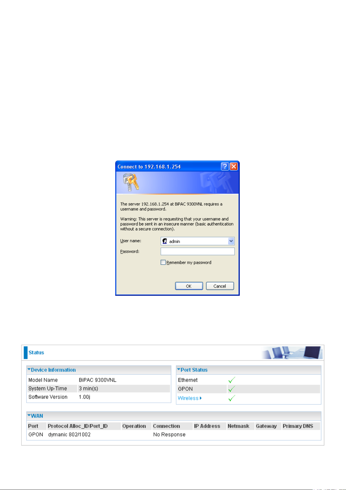
Conguring with your Web Browser
Open your web browser, enter the IP address of your router, which by default is 192.168.1.254,
and click “Go”, a user name and password window prompt will appear. The default username and
password are “admin” and “admin” respectively.
Congratulations! You are now successfully logon to the Gateway Router!
If the authentication succeeds, the homepage Status will appear on the screen.
26
Page 31

Chapter 4: Conguration
Once you have logged on to your router GUI via your web browser, you can begin to congure the
router according to your needs. On the conguration homepage, the left navigation pane provides
the links to different setup pages.
Sections embedded within the Basic Conguration mode:
Advanced (Press to switch to Advanced Conguration mode)
Status
Quick Start
WAN
WLAN
Quick VoIP (Only for 9300VN(X))
Sections embedded within the Advanced Conguration mode:
Basic (Press to switch to Basic Conguration mode)
Status (GPON Status / ARP table / DHCP table / System Log / Firewall Log / VoIP CDR
Log / SIP Accounts (ITSP) / SIP Extensions / VoIP Call Status / UPnP portmap)
Quick Start
Conguration (LAN / WAN / System / Firewall / QoS / Virtual Server / Time Schedule /
Advanced)
Advanced VoIP (Extensions / SIP Accounts (ITSP) / Mini IP-PBX) (Only for 9300VN(X))
Each of these setup pages will be discussed in detail in sections that follow ahead.
27
Page 32

Quick Start
Whether on the Basic or Advanced Conguration Mode, click Quick Start link to WAN Port setup
pages.
1. Select the appropriate connect mode from the drop down menu. Then press Continue to go to
the next conguration page.
2. Press Continue to auto scan for the presence of GPON line.
Note: If the GPON line is not ready, a page will display as below and your new conguration
can not be saved.
3. Congure the WAN, then click Continue. The device will then congure itself. There are several
types of WAN protocol in this version. The detail of these protocols will be discussded in the
next sections.
28
Page 33

4. After your WAN is congured, press Next to Wireless button to proceed with your wireless
conguration.
Note: If the WAN line is not ready, a page will display as below and your new conguration
can not be saved.
5. To activate wireless function, click on the enable radio button and then ll in its ESSID, select its
channel ID and security mode. When it is done, click Continue to apply the setting. The system
will save your conguration and update your new setting.
29
Page 34

Basic Conguration Mode
Status
9300VN(X)
9300N(X)
30
Page 35

Device Information
Model Name: Provide a name for the router for identication purposes.
System Up-Time: Record system up-time.
Software Version: Firmware version.
Port Status
Port Status: User can look up to see if they are connected to Ethernet, GPON and Wireless.
If is shown in GPON, the GPON port has not successfully connected or detected the
optical signal.
If is shown in GPON, the GPON port has correctly connected.
If is shown in GPON, the GPON connection has not been activated by OLT.
WAN
Port: Name of the WAN connection.
Protocol Alloc_ID/Port_ID: Allocation Identier and GEM Port Identier.
Operation: Current status in WAN interface.
Connection: Current connection status.
IP Address: WAN port IP address.
Netmask: WAN port IP subnet mask.
Gateway: IP address of the default gateway.
Primary DNS: IP address of the primary DNS server.
31
Page 36

WAN
For WAN connect mode there are 4 types of connection protocols: PPPoE, Obtain an IP Address
Automatically (DHCP Client), Static IP and Pure Bridge.
PPPoE
PPPoE (PPP over Ethernet) provides access control in a manner which is similar to dial-up services
using PPP.
Protocol: Select the protocol you will use in the device.
ALLOC_ID/PORT_ID: Enter the information provided by your ISP.
Username: Enter the username provided by your ISP. You can input up to 128 alphanumeric
characters (case sensitive). This is the format of username “username@ispname” instead of
“username”.
Password: Enter the password provided by your ISP. You can input up to 128 alphanumeric
characters (case sensitive).
Service Name: This item is for identication purposes. If it is required, your ISP provides you the
information. Maximum input is 15 alphanumeric characters.
Auth. Protocol: Default is Auto. Your ISP should advise you on whether to use Chap or Pap.
IP Address: Your WAN IP address. Leave the IP address as 0.0.0.0 to enable the device to
automatically obtain an IP address from your ISP.
Click Apply to conrm the settings.
32
Page 37

DHCP Client
By conguring DHCP settings, the device is able to obtain IP settings automatically from the ISP.
Protocol: Select the protocol you will use in the device.
ALLOC_ID/PORT_ID: Enter the information provided by your ISP.
Click Apply to conrm the settings.
33
Page 38

Static IP
A Static WAN connection will be congured according to the IP properties dened by your ISP.
Protocol: Select the protocol you will use in the device.
ALLOC_ID/PORT_ID: Enter the information provided by your ISP.
IP Address: Your WAN IP address. Leave this at 0.0.0.0 to obtain automatically an IP address
from your ISP.
Netmask: The default is 255.255.255.0. User can change it to other such as 255.255.255.128.
Type the subnet mask assigned to you by your ISP (if given).
Gateway: Enter the IP address of the default gateway (if given).
Click Apply to conrm the settings.
34
Page 39

Pure Bridge
Protocol: Select the protocol you will use in the device.
ALLOC_ID/PORT_ID: Enter the information provided by your ISP.
Click Apply to conrm the settings.
35
Page 40

WLAN
Wireless Parameters
WLAN Service: Default setting is set to Enable. If you do not have any wireless, select Disable.
ESSID: The ESSID is a unique name of a wireless access point (AP) used to distinguish one from
another. For security purpose, change the default wlan-ap to a unique ID name that is already
built into the router wireless interface. Make sure your wireless clients have exactly the ESSID as
the device in order to connect to your network.
Note: It is case sensitive and must not exceed 32 characters.
Hide ESSID: It is used to broadcast its ESSID on the network so that when a wireless client
searches for a network, the router can be discovered and recognized. Default setting is Disable.
Enable: When enabled, you do not broadcast your ESSID. Therefore, no one will be able to
locate the Access Point (AP) of your router.
Disable: When disabled, you allow anybody with a wireless client to be able to locate the Access Point (AP) of your router.
Regulation Domain: There are seven Regulation Domains for you to choose from, including
North America (N.America), Europe, France, etc. The Channel ID will be different based on this
setting.
Channel ID: Select the wireless connection ID channel that you would like to use.
Note: Wireless performance may degrade if the selected ID channel is already being
occupied by other AP(s).
Security Parameters
Security Mode: You can disable or enable the function with WPA or WEP to protect the wireless
network. The default mode of wireless security is Disable.
36
Page 41

Security Mode
WPA / WPA2 / WPA/WPA2 Pre-Shared Key
Security Mode: You can disable or enable with WPA or WEP for protecting wireless network.
WPA Shared Key: The key for network authentication. The input format is in character style and
key size should be in the range between 8 and 63 characters.
Group Key Renewal: The period of renewal time for changing the security key automatically
between wireless client and Access Point (AP). Default value is 3600 seconds.
WEP
Security Mode: You can disable or enable with WPA or WEP for protecting wireless network.
WEP Authentication: To prevent unauthorized wireless stations from accessing data transmitted
over the network, the router offers secure data encryption, known as WEP. If you require high
security for transmissions, there are three options to select from: Open System, Share key and
Both.
Default Used WEP Key: Select the encryption key ID; please refer to Key (1~4) below.
Passphrase: This is used to generate WEP keys automatically based upon the input string and a
pre-dened algorithm in WEP64 or WEP128.
Key (1-4): Enter the key to encrypt wireless data. To allow encrypted data transmission, the WEP
Encryption Key values on all wireless stations must be the same as the router. There are four keys
for your selection. The input format is in HEX or ASCII style, 5 and 13 ASCII codes are required for
WEP64 and WEP128 or 10 and 26 HEX codes are required for WEP64 and WEP128 respectively.
37
Page 42

Quick VoIP (Only for 9300VN(X))
VoIP provides you the convenience & efciency to make phone calls through your internet
broadband. VoIP technology not only provides all the features and functions that PSTN (Public
Switched Telephone Network) posseses, it also eables you to make international & long distance
phone calls using IP at charging rate much lower than traditional phone. Thus, by using VoIP
technology, you can save more money and embrace more functions.
BiPAC 9300VN(X) has a full support for SIP feature, it also has 2 fxs ports and a fxo port. User can
apply for an SIP account from a phone company that offers internet phone service. You can then
call your friends as you will use a traditional phone through the SIP account. In addition, the built
in SIP proxy server feature also provides SIP phone terminal registration and connection within a
company.
Quick VoIP provides a quick and simple way to congure the basic setting of your VoIP setting
under the basic conguration mode.
38
Page 43

SIP Accounts
SIP account is the SIP server that makes connection to the external VoIP service provider easy to
establish. You can click SIP Accounts Setting and ITSP links to congure SIP accounts.
Extensions
The BiPAC router comes with 2 built in phone ports (FXS port) that enables the device to connect
up to 2 phones. You can click FXS Extensions and SIP Extensions links to congure SIP
Extensions.
Mini IP-PBX
Please click Inbound Rules, Outbound Rules, Speed Dial, Call Feature and Setting links to
congure Mini IP-PBX parameters.
For VoIP conguration please refer to the Advanced VoIP section for detail description.
39
Page 44

Advanced Conguration Mode
Status
9300VN(X)
9300N(X)
40
Page 45

Device Information
Model Name: Displays the model name.
Host Name: Provide a name for the router for identication purposes. Host Name lets you change
the router name.
System Up-Time: Records system up-time.
Current Time: Set the current time. See the Time Zone section for more information.
Software Version: Firmware version.
MAC Address: The LAN MAC address.
Serial Number: Displays the serial number of this router.
Port Status
Port Status: User can look up to see if they are connected to Ethernet, GPON and Wireless.
If is shown in GPON, the GPON port has not successfully connected or detected the
optical signal.
If is shown in GPON, the GPON port has correctly connected.
If is shown in GPON, the GPON connection has not been activated by OLT.
WAN
Port: Name of the WAN connection.
Protocol Alloc_ID/Port_ID: Allocation Identier and GEM Port Identier.
Operation: The current status in WAN interface.
Connection: The current connection status.
IP Address: WAN port IP address.
Netmask: WAN port IP subnet mask.
Gateway: The IP address of the default gateway.
Primary DNS: The IP address of the primary DNS server.
41
Page 46

GPON Status
This section displays the overall status of GPON, such as DSP rmware version, Optical Signal,
Admin Status and Sub Status.
DSP Firmware Version: DSP code version
Optical Signal: Current signal status
Admin Status: Current admin status
Sub Status: Show the state of GPON operation.
Note: Admin Status shows “Active” and Sub Status shows “Standby” when the router is
ready. Admin Status shows “Active” and Sub Status shows “Operational” when the GPON
connection is operated.
42
Page 47

ARP Table
This section displays the router ARP (Address Resolution Protocol) Table which shows the
mapping of Internet (IP) addresses to Ethernet (MAC) addresses. This is a quick way of
determining the MAC address of the network interface of your PCs that use the Firewall – MAC
Address Filter function. See the Firewall section of this manual for more information on this
feature.
IP Address: Shows a list of IP addresses of devices on your LAN (Local Area Network).
MAC Address: Shows the MAC (Media Access Control) addresses of each device on your LAN.
Interface: Shows the interface for the ARP item.
Static ARP: Shows the state of the static ARP item.
43
Page 48

DHCP Table
The DHCP Table lists the DHCP lease information for all IP addresses assigned by the DHCP
server in the device.
IP Address: The current corresponding DHCP-assigned dynamic IP address of the device.
MAC Address: The MAC Address of internal dhcp client host.
Client Host Name: The Host Name of the internal dhcp client.
Register Information: Register time information.
44
Page 49

System Log
Display system logs accumulated up to the present time. You can trace its historical information
with this function.
Refresh: Click to update the system log.
Clear: Click to clear the current log from the screen.
45
Page 50

Firewall Log
Firewall Log displays the log information of any unexpected events that occurs to your rewall
settings. This page displays the router Firewall Log entries which have been recorded when you
have enabled Intrusion Detection or Block WAN PING in the Conguration – Firewall section of the
interface. Please see the Firewall section of this manual for more details on how to enable Firewall
event logging.
46
Page 51

VoIP CDR Log (Only for 9300VN(X))
Display VoIP CDR logs accumulated up to the present time. You can see the associated
information, including Caller, Callee, Start Time, End Time, Duration, Talk and Disposition, with this
function.
47
Page 52

SIP Accounts Status (ITSP) (Only for 9300VN(X))
This section lists the informaion of all the SIP accounts.
SIP Account: Display all the SIP accounts.
Phone Number: The phone number of the SIP account.
User Name: The registered user name of the SIP account.
Service Provider: The VoIP service provider for the SIP account.
Direct Inward Dial: The direct inward dial of the SIP account.
Status: The connection state of the SIP account.
48
Page 53

SIP Extensions Status (Only for 9300VN(X))
Displays the information of SIP extensions.
Phone Number: The phone number of the SIP extended connection.
Display Name: The name of this connection.
Status: The state of this connection.
Host: The host name of this connection.
49
Page 54

VoIP Call Status (Only for 9300VN(X))
VoIP (Voice over Internet Protocol) is a technology for delivery of voice communications over IP
networks such as the Internet. It involves in originating an Internet telephone call conversing the
analog voice signal to digital format and compressing/translating the signal into Internet protocol
packets for transmission over the Internet; the process is reversed at the receiving end.
This page displays the information of VoIP Call.
Caller: The terminal of the caller that initiates the call.
Callee: The terminal of the callee that is being called.
Time: The length of time for this VoIP call.
Status: The state of this VoIP call.
50
Page 55

UPnP Portmap
This section lists all the established port-mapping using UPnP (Universal Plug and Play).
Name: The Host Name of the internal UPNP client.
Protocol: The connection protocol of the UPNP client.
External Port: The external port for this connection.
Internal Port: The internal port for this connection.
IP Address: IP of the internal UPNP client.
51
Page 56

Conguration
When you click this item, the column will expand to display the sub-items that will allow you to further
congure your GPON router.
LAN, WAN, System, Firewall, QoS, Virtual Server, Time Schedule and Advanced
The function of each conguration sub-item is described in the following sections.
52
Page 57

LAN - Local Area Network
A Local Area Network (LAN) is a shared communication system to which many computers are
attached together and is limited to the immediate area, usually within the same building or storey
of a building.
These are the items within the LAN section: Ethernet, IP Alias, Wireless, Wireless Security,
WPS and DHCP Server.
Ethernet
The router supports more than one Ethernet IP addresses in the LAN that supports multiple internet
access at the same time. Users usually only have one subnet in their LAN. The default IP address
for the router is 192.168.1.254.
IP Address: The default IP address of this router.
Netmask: The default subnet mask of this router.
RIP: RIP v1, RIP v2 Broacast, RIP v2 Multicast and RIP v1+v2 Broacast. Check to enable RIP
function.
Click Apply to conrm the settings.
53
Page 58

IP Alias
This function enables the creation of multiple virtual IP interfaces for this router. It helps to connect two
or more local networks to the ISP or remote node. In this case, an internal router is not required.
IP Address: Specify an IP address for this virtual interface.
Netmask: Specify a subnet mask for this virtual interface.
Click Add to conrm the settings.
54
Page 59

Wireless
Parameters
WLAN Service: Default setting is set to Enable. If you do not have any wireless, select Disable.
Mode: The default setting is 802.11b+g+n (Mixed mode). If you do not know or do not have both
11g and 11b devices on your network, then keep the setting in mixed mode. From the drop-down
menu, you can select 802.11g if you have only 11g card. If you have only 11b card, then select
802.11b. And if you have 11n card, select 802.11n.
ESSID: The ESSID is a unique name of a wireless access point (AP) used to distinguish one from
another. For security purpose, change to a unique ID name which is already built into the router
wireless interface. It is case sensitive and must not exceed 32 characters. Make sure your wireless
clients have exactly the ESSID as the device in order to connect to your network.
Hide ESSID: This function enables the router to become invisible on the network. Thus, any
clients using the wireless setting to search for available or specic router on the network will not
be able to discover the router whose Hide ESSID function is set to enabled. The default setting is
disabled.
Enable: When enabled, you do not broadcast your ESSID. Therefore, no one will be able to
locate the Access Point (AP) of your router.
Disable: When disabled, you allow anybody with a wireless client to be able to locate the Access Point (AP) of your router.
55
Page 60

Regulation Domain: There are seven Regulation Domains for you to choose from, including
North America (N.America), Europe, France, etc. The Channel ID will be different based on this
setting.
Channel ID: Select the wireless connection ID channel that you would like to use.
Note: Wireless performance may degrade if the selected ID channel is already being
occupied by other AP(s).
Channel width: Select either 20 MHz or 20/40 MHz for the channel bandwidth. The higher the
bandwidth the better the performance will be.
TX PowerLevel: It is a function that enhances the wireless transmission signal strength. User
may adjust this power level from minimum 0 up to maximum 100.
Note: The power level may be different in each accss network uer premise environment, so
choose the most suitable level for your network.
AP MAC Address: It is a unique hardware address of the Access Point.
AP Firmware Version: The Access Point rmware version.
WPS Service: Select Enable if you would like to activate WPS service.
WPS State: You can set the WPS state as Congured or Uncongured.
WMM: This feature is used to control the prioritization of trafc according to 4 Access categories:
Voice, Video, Best Effort and Background. Default is set to disable.
Wireless Distribution System (WDS)
It is a wireless access point mode that enables wireless link and communication with other access
points. It is easy to install simply by dening the peer’s MAC address of the connected AP. WDS
takes advantage of the cost saving and flexibility which no extra wireless client device is required to
bridge between two access points and extending an existing wired or wireless infrastructure network
to create a larger network. It can connect up to 4 wireless APs for extending cover range at the same
time.
In addition, WDS also enhances its link connection security mode. Key encryption and channel
must be the same for both access points.
WDS Service: The default setting is disabled. Check Enable radio button to activate this function.
Peer WDS MAC Address: It is the associated AP’s MAC Address. It is important that your peer’s
AP must include your MAC address in order to acknowledge and communicate with each other.
1. Peer WDS MAC Address: It is the second associated AP’s MAC Address.
2. Peer WDS MAC Address: It is the third associated AP’s MAC Address.
3. Peer WDS MAC Address: It is the fourth associated AP’s MAC Address.
Note: For MAC Address, semicolon ( : ) must be included.
You can click Security settings link next to Cancel button to go to Wireless Security screen (see
Wireless Security section).
Click Apply to conrm the settings.
56
Page 61

Wireless Security
You can disable or enable the wireless security function using WPA or WEP for wireless network
protection.
The default mode of wireless security is disabled.
WPA / WPA2 / WPA/WPA2 Pre-Shared Key
Security Mode: You can disable or enable with WPA or WEP for protecting wireless network.
WPA Algorithms: There are 3 types of the WPA-PSK, WPA2-PSK & WPA/WPA2-PSK. The WPA-
PSK adapts the TKIP (Temporal Key Integrity Protocol) encrypted algorithms, which incorporates
Message Integrity Code (MIC) to provide protection against hackers. The WPA2-PSK adapts
CCMP (Cipher Block Chaining Message Authentication Code Protocol) of the AES (Advanced
Encryption Security) algorithms.
WPA Shared Key: The key for network authentication. The input format is in character style and
key size should be in the range between 8 and 63 characters.
Group Key Renewal: The period of renewal time for changing the security key automatically
between wireless client and Access Point (AP). Default value is 3600 seconds.
Click Apply to conrm the settings.
57
Page 62

WEP
Security Mode: You can disable or enable with WPA or WEP for protecting wireless network.
WEP Authentication: To prevent unauthorized wireless stations from accessing data transmitted
over the network, the router offers secure data encryption, known as WEP. If you require high
security for transmissions, there are three options to select from: Open System, Share Key or
Both.
Default Used WEP Key: Select the encryption key ID; please refer to Key (1~4) below.
Passphrase: This is used to generate WEP keys automatically based upon the input string and a
pre-dened algorithm in WEP64 or WEP128.
Key (1~4): Enter the key to encrypt wireless data. To allow encrypted data transmission, the WEP
Encryption Key values on all wireless stations must be the same as the router. There are four keys
for your selection. The input format is in HEX or ASCII style, 5 and 13 ASCII codes are required for
WEP64 and WEP128 or 10 and 26 HEX codes are required for WEP64 and WEP128 respectively.
Click Apply to conrm the settings.
58
Page 63

WPS
WPS (WiFi Protected Setup) feature is a standard protocol created by Wi-Fi Alliance. This feature
greatly simplies the steps needed to create a Wi-Fi networks for a residential or an ofce setting.
WPS supports two types of conguration methods which are commonly known among consumers:
PIN Method & PBC Method.
59
Page 64

Wi-Fi Network Setup
PIN Method: Congure AP as Registrar
1. Jot down the client’s Pin (eg. 16837546).
2. Enter the Enrollee’s PIN number and then press Start.
3. Launch the wireless client’s WPS utility (eg. Ralink Utility). Set the Cong Mode as Enrollee,
press the WPS button on the top bar, select the AP (eg. wlan-ap) from the WPS AP List column.
Then press the PIN button located on the middle left of the page to run the scan.
60
Page 65

4. The client’s SSID and security setting will now be congured to match the SSID and security
setting of the registrar.
61
Page 66

PIN Method: Congure AP as Enrollee
1. In the WPS conguration page, change the Role to Enrollee. Then press Start.
2. Jot down the WPS PIN (eg. 25879810).
3. Launch the wireless client’s WPS utility (eg. Ralink Utility). Set the Cong Mode as Registrar.
Enter the PIN number in the PIN Code column then choose the correct AP (eg. wlan-ap) from
the WPS AP List section before pressing the PIN button to run the scan.
62
Page 67

4. The router’s (AP’s) SSID and security setting will now be congured to match the SSID and
security setting of the registrar.
5. Now to make sure that the setup is correctly done, cross check to see if the SSID and the security
setting of the registrar setting match with the parameters found on both Wireless Conguration
and Wireless Security Conguration page.
63
Page 68

646566
Page 69

Page 70

PBC Method:
1. Press the PBC button of the AP.
2. Launch the wireless client’s WPS Utility (eg. Ralink Utility). Set the Cong Mode as Enrollee.
Then press the WPS button and choose the correct AP (eg. wlan-ap) from the WPS AP List
section before pressing the PBC button to run the scan.
Page 71

3. When the PBC button is pushed, a wireless communication will be established between your
router and the PC. The client’s SSID and security setting will now be congured to match the
SSID and security setting of the router.
67
Page 72

Wi-Fi Network Setup with Windows Vista WCN:
1. Jot down the AP PIN from the Web (eg. 25879810).
2. Access the Wireless conguration of the web GUI. Set the WPS State to Uncongured then
click Apply.
3. In your Vista operating system, access the Control Panel page, then select Network and Inter-
net > View Network Computers and Devices. Double click on the BiPAC 9300VN(X)/9300N(X)
icon and enter the AP PIN in the column provided then press Next.
68
Page 73

4. Enter the AP SSID then click Next.
5. Enter the passphrase then click Next.
69
Page 74

6. When you have come to this step, you will have comleted the Wi-Fi network setup using the
built-in WCN feature in Windows Vista.
70
Page 75

DHCP Server
DHCP allows networked devices to obtain information on the parameter of IP, Netmask, Gateway as
well as DNS through the Ethernet Address of the device.
To congure the router’s DHCP Server, select DHCP Server from the DHCP Server Mode drop-
down menu. You can then congure parameters of the DHCP Server including the domain, IP pool
(starting IP address and ending IP address to be allocated to PCs on your network), lease time
for each assigned IP address (the period of time the IP address assigned will be valid), DNS IP
address and the gateway IP address. These details are sent to the DHCP client (i.e. your PC) when
it requests an IP address from the DHCP server. If you check “Use Router as a DNS Server”, the
GPON Router will perform the domain name lookup, nd the IP address from the outside network
automatically and forward it back to the requesting PC in the LAN (your Local Area Network). Click
Apply to enable this function.
If you select DHCP Relay from the DHCP Server Mode drop-down menu, you must enter the IP
address of the DHCP server that assigns an IP address to the DHCP client in the LAN. Use this
function only if advised to do so by your network administrator or ISP. Click Apply to enable this
function.
71
Page 76

WAN - Wide Area Network
WAN refers to your Wide Area Network connection, i.e. your router’s connection to your ISP and the
Internet.
WAN Prole
PPPoE Connection
PPPoE (PPP over Ethernet) provides access control in a manner which is similar to dial-up services
using PPP.
Protocol: Select the protocol you will use in the device.
Alloc_ID/Port_ID: Enter the information provided by your ISP.
Username: Enter the username provided by your ISP. You can input up to 128 alphanumeric
characters (case sensitive). This is the format of username “username@ispname” instead of
“username”.
Password: Enter the password provided by your ISP. You can input up to 128 alphanumeric
characters (case sensitive).
Service Name: This item is for identication purposes. If it is required, your ISP provides you the
information. Maximum input is 15 alphanumeric characters.
NAT: The NAT (Network Address Translation) feature allows multiple users to access the Internet
through a single IP account, sharing the single IP address. If users on your LAN have public IP
addresses and can access the Internet directly, the NAT function can be disabled.
IP (0.0.0.0:Auto): Your WAN IP address. Leave this at 0.0.0.0 to obtain automatically an IP
address from your ISP.
Auth. Protocol: Default is Auto. Your ISP should advise you on whether to use Chap or Pap.
Obtain DNS: A Domain Name System (DNS) contains a mapping table for domain name and IP
addresses. DNS helps to nd the IP address for the specic domain name. Check the checkbox
to obtain DNS automatically.
Primary DNS: Enter the primary DNS.
Secondary DNS: Enter the secondary DNS.
72
Page 77

Connection:
Always on: If you want the router to establish a PPPoE session when starting up and to
automatically re-establish the PPPoE session when disconnected by the ISP.
Idle Timeout: Auto-disconnect the broadband rewall gateway when there is no activity on the line
for a predetermined period of time.
MTU: Maximum Transmission Unit. The size of the largest datagram (excluding media-specic
headers) that IP will attempt to send through the interface.
Click Apply to conrm the settings.
73
Page 78
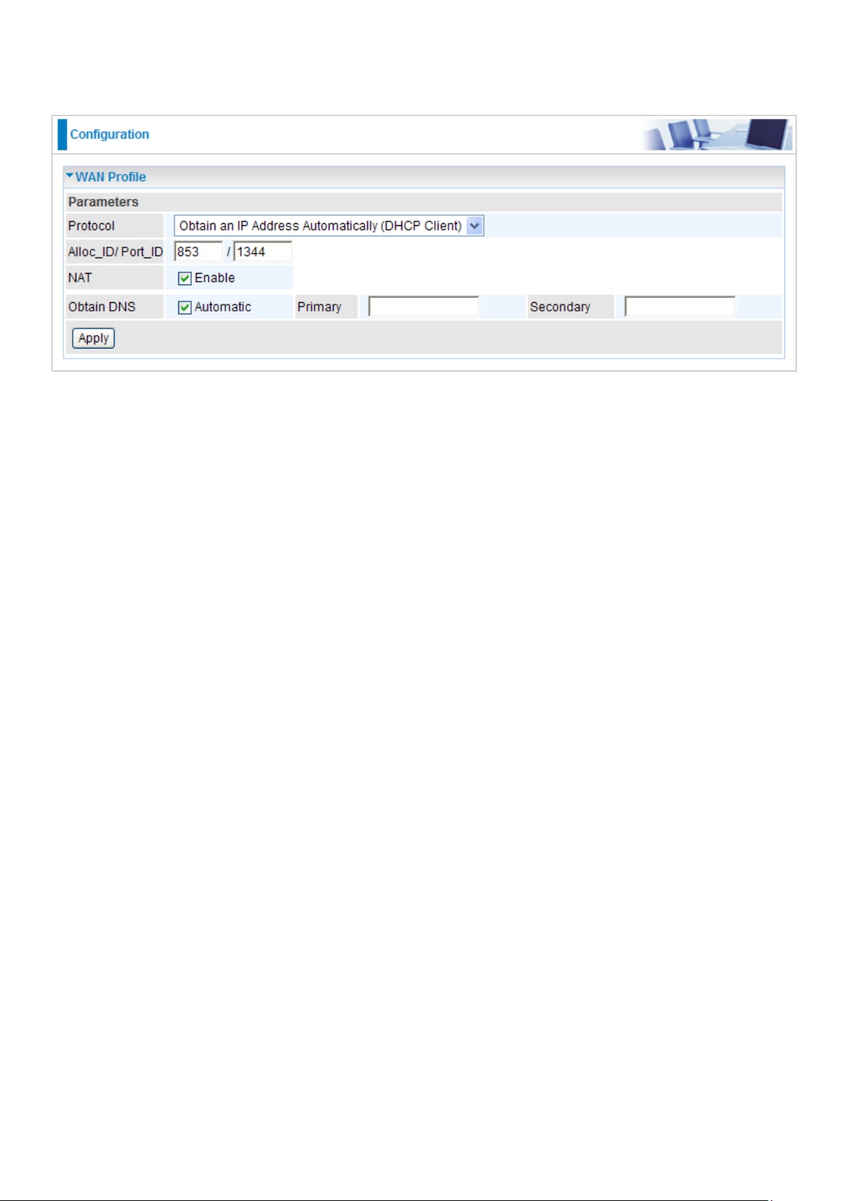
Obtain an IP Address Automatically (DHCP Client)
By conguring DHCP settings, the device is able to obtain IP settings automatically from the ISP.
Protocol: Select the protocol you will use in the device.
Alloc_ID/Port_ID: Enter the information provided by your ISP.
NAT: The NAT (Network Address Translation) feature allows multiple users to access the Internet
through a single IP account, sharing the single IP address. If users on your LAN have public IP
addresses and can access the Internet directly, the NAT function can be disabled.
Obtain DNS: A Domain Name System (DNS) contains a mapping table for domain name and IP
addresses. DNS helps to nd the IP address for the specic domain name. Check the checkbox
to obtain DNS automatically.
Primary DNS: Enter the primary DNS.
Secondary DNS: Enter the secondary DNS.
Click Apply to conrm the settings.
74
Page 79

Static IP
A Static WAN connection will be congured according to the IP properties dened by your ISP.
Protocol: Select the protocol you will use in the device.
Alloc_ID/Port_ID: Enter the information provided by your ISP.
NAT: The NAT (Network Address Translation) feature allows multiple users to access the Internet
through a single IP account, sharing a single IP address. If users on your LAN have public IP
addresses and can access the Internet directly, the NAT function can be disabled.
IP (0.0.0.0:Auto): Specify an IP address allowed to logon and access the router’s web server.
Note: IP 0.0.0.0 indicates all users who are connected to this router are allowed to logon the
device and modify data.
Netmask: The default is 255.255.255.0. Type the subnet mask assigned to you by your ISP (if
given).
Gateway: Enter the IP address of the default gateway (if given).
Obtain DNS: A Domain Name System (DNS) contains a mapping table for domain name and IP
addresses. DNS helps to nd the IP address for the specic domain name. Check the checkbox
to obtain DNS automatically.
Primary DNS: Enter the primary DNS.
Secondary DNS: Enter the secondary DNS.
Click Apply to conrm the settings.
75
Page 80

Pure Bridge
Protocol: Select the protocol you will use in the device.
Alloc_ID/Port_ID: Enter the information provided by your ISP.
Click Apply to conrm the settings.
76
Page 81

System
These are the items within the System section: Time Zone, Firmware Upgrade, Backup/Restore,
Restart, User Management and Mail Alert.
Time Zone
The router does not have a real time clock on board; instead, it uses the Simple Network Time
Protocol (SNTP) to get the current time from an SNTP server outside your network. Choose your
local time zone from the drop down menu. To apply the selected local time zone, check Enable and
click the Apply button. After a successful connection to the Internet, the router will retrieve the correct
local time from the SNTP server you have specied. If you prefer to specify an SNTP server other
than those in the drop-down list, simply enter its IP address in their appropriate blanks provided as
shown above. Your ISP may also provide an SNTP server for you to use.
Daylight Saving is also known as Summer Time Period. Many places in the world adapt it during
summer time to move one hour of daylight from morning to the evening in local standard time. Check
Enable box to set your local time.
Resync Period (in minutes) is the periodic interval the router will wait before it re-synchronizes the
router’s time with that of the specied SNTP server. In order to avoid unnecessarily increasing the
load on your specied SNTP server you should keep the poll interval as high as possible – at the
absolute minimum every few hours or even days. The default value is set at 1440 minutes.
77
Page 82

Firmware Upgrade
Your router’s rmware is the software that enables it to operate and provides all its functionality.
Think of your router as a dedicated computer, and the rmware as the software that runs in your
router. Thus, by upgrading the newly improved version of the rmware allows you the advantage to
use newly integrated features.
Factory Default Settings: If select this setting, the device will reboot to restore the parameters of
all its applications to its default values.
Current Settings: If select this setting, the device will reboot and retain the customized settings of
all applications.
Click on Browse button to select the new rmware image le you have downloaded to your PC.
Once the correct le is selected, click Upgrade to update the rmware to your router.
78
Page 83

Backup / Restore
These functions allow you to save a backup of the current conguration of your router to a dened
location on your PC, or to restore a previously saved conguration. This is useful if you wish to
experiment with different settings, knowing that you have a backup in hand in case any mistakes
occur. It is advisable that you backup your router conguration before making any changes to your
router conguration.
Backup Conguration
Press Backup to select where on your local PC you want to store your setting le. You may also
change the name of the le if you wish to keep multiple backups.
Restore Conguration
Press Browse to select a le from your PC to restore. You should only restore your router setting that
has been generated by the Backup function which is created with the current version of the router
rmware. Settings les saved to your PC should not be manually edited in any way.
Select the settings les you wish to use, and press Update Settings to load the setting into the router.
Click Restore to begin restoring the conguration and wait for the router to restart before performing
any actions.
79
Page 84

Restart
There are two options for you to choose from before restarting the your 9300(V)NX device. You
can either choose to restart your device to restore it to the Factory Default Settings or to restart the
device with your current settings applied. Restarting your device to Factory Default Setting will be
useful especially after you have accidentally changed your settings that may result in undesirable
outcome.
If you wish to restart the router using the factory default settings (for example, after a rmware
upgrade or if you have saved an incorrect conguration), select Factory Default Settings to reset to
factory default settings.
Click Restart with option Current Settings to reboot your router (and restore your last saved
conguration).
After selecting the type of setting you want the device to restart with, click the Restart button to
initiate the process. After restarting, please wait several minutes to let the selected setting applied
to the system.
You may also reset your router to factory settings by holding the small Reset pinhole button more
than 6 seconds on the back of your router.
80
Page 85

User Management
In order to prevent unauthorized access to your router conguration interface, it requires all users
to login with a username and password. Therefore only system administrator can access the
system.
This feature allows you to set up multiple user accounts which contains a unique password of its
own. In addition, you can also edit any existing user accounts or add new users to allow access to
the device conguration interface.
Edit Account Information
You can change the informations of any account whether the account is active or valid.
1. To edit an account, click on the Edit radio button of the account you want to edit. Once selected,
all information of that account will be displayed.
2. Delete the information to be edited and replace it with the new one.
3. When it is done, simply click on the Edit/ Delete button to save your changes.
Note: It is highly recommended that you change the password immediately to prevent
security breach to your GUI.
81
Page 86

Add an Account
1. Check the Valid checkbox, ll in all the information: User name, Comment (optional), Password,
Conrm Password.
2. When it is done, click the Add button.
Delete a user account
1. Check the Delete checkbox of the account you want to delete.
2. Then click the Edit/Delete to conrm the deletion.
Note: You can delete any user account except for the default admin account. Thus there is
no delete radio button available for this account.
82
Page 87

Mail Alert
Mail Alert allows administrator to receive notications from the router through email about
important events that is occurring in real time. This allows administrator to be able to take
immediate actions to counteract any possible hacking or to restore the router to its original status
should any failover / failback ever occurs.
Server Information
SMTP Server: Enter the SMTP (mail) server address.
Username: Enter the username of your SMTP server.
Password: Enter the password associated with the username.
Sender’s E-mail: Enter the email address you wish to send the mail alert email to.
WAN IP Change Alert
Recipient’s E-mail: Enter the email address you wish to send the WAN IP Change email to.
Intrusion Detection
Alert Mail Time: Set the time for sending the Alert mail.
Recipient’s E-mail: Enter the email address you wish to send the Intrusion Detection email to.
Click Apply to conrm the settings.
83
Page 88

Firewall
Listed are the items under the Firewall section: Packet Filter, MAC Filter, Intrusion Detection,
Block WAN PING and URL Filter.
Packet Filter
Packet ltering enables you to congure your router to block specic internal / external users (IP
address) from Internet access, or disable specic service requests (Port number) to / from the
Internet. This conguration program allows you to set up different lter rules for different users
based on their IP addresses or their network Port number. The relationship among all lters is “or”
operation, which means that the router checks these different lter rules one by one, starting from
the rst rule. As long as one of the rules is satised, the specied action will be taken.
Rule Name: User dened description for entry identication. The maximum name length is 20
characters, or choose an application that you want from the listbox.
Internal IP Address / External IP Address: This is the Address-Filter used to allow or block trafc
to/rom particular IP address(es). Input the range you want to lter out. If you leave these four elds
empty or enter 0.0.0.0, it means any IP address.
Protocol: Specify the packet type (TCP, UDP, ICMP, etc.) that the rule applies to. Select TCP if
you wish to search for the connection-based application service on the remote server using the
port number. Or select UDP if you want to search for the connectionless application service on the
remote server using the port number.
Action: If a packet matches this lter rule, forward (allows the packets to pass) or drop (disallow
the packets to pass) this packet.
Internal Port: This Port or Port Range denes the ports allowed to be used by the Remote/WAN
to connect to the application. Default is set from range 0 ~ 65535. It is recommended that this
option be congured by an advanced user.
External Port: This is the Port or Port Range that denes the application.
Direction: Determine whether the rule is for outgoing packets or for incoming packets.
84
Page 89

Time Schedule: It is self-dened time period. You may specify a time schedule for your
prioritization policy. For setup and detail, refer to Time Schedule section.
Log: Check the checking box if you wish to generate logs when the ler rule is applied to a packet.
Add: Click this button to add a new packet lter rule and the added rule will appear at the bottom
table.
Edit: Tick Edit next to the item you wish to edit, and then change parameters as desired. Complete
it by press “Edit/Delete”.
Delete: Tick Delete next to the item you wish to delete, and press “Edit/Delete” to remove this rule.
Order: Be aware that packet ltering parameters appear in priority order i.e. the rst one takes
precedence over all other rules. There is a sort function next to the Rule Name column, you can
move the rule to higher or lower priority by clicking the Order arrow, and press “Reorder” to save
the new priority.
85
Page 90

MAC Filter
A MAC (Media Access Control) address is the unique network hardware identier for each PC on
your network’s interface (i.e. its Network Interface Card or Ethernet card). Using your router’s MAC
Address Filter function, you can congure the network to block specic machines from accessing
your LAN.
There are no pre-dened MAC address lter rules, you can add the lter rules to meet your
requirements.
The format of MAC address could be: xx:xx:xx:xx:xx:xx or xx-xx-xx-xx-xx-xx.
Filter Action
Action: Select an action for MAC Filter. Default is Block. You can check Disable this feature or
Allow to activate the lter. Click Apply to conrm the change.
Server Information
MAC Address: Enter the MAC addresses you wish to have the lter rule applies.
Time Schedule: It is a self-dened time period. You may specify a time schedule for your
prioritization policy. For setup and detail, refer to Time Schedule section.
Click Add to apply the settings.
86
Page 91

Intrusion Detection
The router Intrusion Detection System (IDS) is used to detect hacker’s attack and intrusion
attempts from the Internet. If the IDS function of the rewall is enabled, inbound packets are
ltered and blocked depending on whether they are detected as possible hacker attacks, intrusion
attempts or other connections that the router determines to be suspicious.
Intrusion Detection: Check Enable if you wish to detect intruders accessing your computer
without permission.
Maximum TCP Open Handshaking Count: This is a threshold value to decide whether a SYN
Flood attempt is occurring or not. Default value is 100 TCP SYN per seconds.
Maximum Ping Count: This is a threshold value to decide whether an ICMP Echo Storm is
occurring or not. Default value is 15 ICMP Echo Requests (PING) per second.
Maximum ICMP Count: This is a threshold to decide whether an ICMP ood is occurring or not.
Default value is 100 ICMP packets per seconds except ICMP Echo Requests (PING).
Log: Check Log if you wish to generate logs when the ler rule is applied to the Intrusion
Detection.
Click Apply to conrm the settings.
87
Page 92

Table: Hacker attack types recognized by the IDS
Intrusion Name Detect Parameter Blacklist
Ascend Kill Ascend Kill data Src IP DoS Yes Yes
TCP
WinNuke
Smurf
Land attack SrcIP = DstIP Yes Yes
Echo/CharGen
Scan
Echo Scan
CharGen Scan
Port 135, 137~139,
Flag: URG
ICMP type 8
Des IP is broadcast
UDP Echo Port and
CharGen Port
UDP Dst Port =
Echo(7)
UDP Dst Port =
CharGen(19)
Src IP DoS Yes Yes
Dst IP
Src IP Scan Yes Yes
Src IP Scan Yes Yes
Type of Block
Duration
Victim
Protection
Drop Packet Show Log
Yes Yes
Yes Yes
X’mas Tree Scan TCP Flag: X’mas Src IP Scan Yes Yes
IMAP
SYN/FIN Scan
SYN/FIN/RST/ACK
Scan
Net Bus Scan
Back Orice Scan
TCP Flag: SYN/FIN
DstPort: IMAP(143)
SrcPort: 0 or 65535
TCP
No Existing session
And Scan Hosts more
than ve.
TCP
No Existing session
DstPort = Net Bus
12345,12346, 3456
UDP, DstPort = Orice
Port (31337)
Src IP Scan Yes Yes
Src IP Scan Yes Yes
SrcIP Scan Yes Yes
SrcIP Scan Yes Yes
SYN Flood
ICMP Flood
ICMP Echo
Max TCP Open
Handshaking Count
(Default 100 c/sec)
Max ICMP Count
(Default 100 c/sec)
Max PING Count
(Default 15 c/sec)
Yes
Yes
Yes
88
Page 93

Src IP: Source IP
Src Port: Source Port
Dst Port: Destination Port
Dst IP: Destination IP
89
Page 94

Block WAN PING
This feature is to be enabled when you want the public WAN IP address on your router not to
respond to any ping command.
This feature is disabled by default. To activate the Block WAN PING feature, check the Enable box
then click the Apply button.
90
Page 95

URL Filter
URL (Uniform Resource Locator) (e.g. an address in the form of http://www.abcde.com or http://
www.example.com) lter rule allows you to prevent users on your network from accessing specic
websites dened by their URL. There are no predened URL lter rules, therefore you can add
lter rules to meet your requirements.
Keywords Filtering: Allow blocking against specic keywords within a particular URL rather
than having to specify a complete URL (e.g. to block any image called “advertisement.gif”). When
enabled, your specied keywords list will be checked to see if any keywords are present in URLs
accessed to determine if the connection attempt should be blocked. Please note that the URL lter
blocks web browser (HTTP) connection attempts using port 80 only.
For example, if the URL is http://www.abc.com/abcde.html, it will be dropped as the keyword
“abcde” occurs in the URL.
Domains Filtering: This function checks the whole URL not the IP address, in URLs accessed
against your list of domains to block or allow. If it is matched, the URL request will be sent (Trusted)
or dropped (Forbidden). For this function to be activated, both check-boxes must be checked. Here
is the checking procedure:
1. Check the domain in the URL to determine if it is in the trusted list. If yes, the connection attempt
is sent to the remote web server.
2. If not, check if it is listed in the forbidden list. If yes, then the connection attempt will be
dropped.
3. If the packet does not match either of the above two items, it is sent to the remote web server.
91
Page 96

4. Please be note that the completed URL, “www” + domain name shall be specied. For example
to block trafc to www.google.com.au, enter “www.google” or “www.google.com”.
Restrict URL Features: This function enhances the restriction to your URL rules.
Block Java Applet: Blocks Web content which includes the Java Applet to prevent someone
who wants to damage your system via the standard HTTP protocol.
Block ActiveX: Blocks ActiveX.
Block Cookies: Blocks Cookies.
Block Proxy: Blocks Proxy.
Except IP Address: The except IP address list.
Time Schedule: It is self-dened time period. You may specify a time schedule for your
prioritization policy. For setup and detail, refer to Time Schedule section.
Log: Check this checking box if you wish to generate logs when the ler rule is applied to the URL
Filter.
Click Apply to conrm the settings.
92
Page 97

QoS - Quality of Service
QoS helps you to control the data upload trafc of each application from LAN (Ethernet and/
or Wireless) to WAN (Internet). It facilitates you the features to control the quality and speed of
throughput for each application when the system is running with full upstream load.
After clicking the QoS item, you can Add/Edit/Delete a QoS policy. This page will show the brief
information for policies you have added or edited. This page will also display the total available
(Non-assigned) bandwidth, in percentage, can be assigned.
Application: Assign a name that identies the new QoS application rule.
Direction: The trafc ow direction to be controlled by the QoS policy. There are two settings to be
provided in the Router:
LAN to WAN: Control the trafc ow from the local network to the outside world. For example,
when you have a FTP server inside the local network and want to have a limited trafc rate
controlled by the QoS policy, you need to add a policy with LAN to WAN direction setting.
WAN to LAN: Control Trafc ow from the WAN to LAN. (The connection maybe either issued
from LAN to WAN or WAN to LAN.)
Protocol: Select the supported protocol from the drop down list. For GRE protocol, there is no
need to specify the IP addresses or Application ports in this page. For other protocols, at least one
value shall be given.
Any: No protocol type is specied.
TCP
UDP
ICMP
GRE: For PPTP VPN Connections.
93
Page 98

DSCP Marking: Differentiated Services Code Point (DSCP), it is the rst 6 bits in the ToS byte.
DSCP Marking allows users to classify the trafc of the application to be executed according to
the DSCP value. See DSCP Mapping Table.
Note: Make sure that the router(s) in the network backbone are capable to execute and check
the DSCP throughout the QoS network.
DSCP Mapping Table
DSCP Mapping Table
(Wireless) GPON Router Standard DSCP
Disabled None
Best Effort Best Effort (000000)
Premium Express Forwarding (101110)
Gold service (L) Class 1, Gold (001010)
Gold service (M) Class 1, Silver (001100)
Gold service (H) Class 1, Bronze (001110)
Silver service (L) Class 2, Gold (010010)
Silver service (M) Class 2, Silver (010100)
Silver service (H) Class 2, Bronze (010110)
Bronze service (L) Class 3, Gold (011010)
Bronze service (M) Class 3, Silver (011100)
Bronze service (H) Class 3, Bronze (011110)
Rate Type: Two types are provided:
Limited (Maximum): Specify a limited data rate for this policy. It is the maximal rate for this
policy. As above FTP server example shows, if you want to “throttle” the outgoing FTP speed
to 20% of 100M and limit to it, please choose this type.
Guaranteed (Minimum): Specify a minimal data rate for this policy. For example, if you want to
provide a guaranteed data rate for your outside customers to access your internal FTP server
with, say at least, 20% of your total bandwidthm, please choose this type. Then, if the available
bandwidth is not used, it will be given to this policy by following priority assignment.
Ratio: Assign the data ratio for this policy to be controlled. For examples, when we want to allow
only 20% of the total data transfer rate for the LAN-to-WAN direction to be used for FTP server, we
can specify here with data ratio = 20. If you have GPON LINE with 100M/bps.rate, the estimated
data rate, in kbps, for this rule is 20%*100*0.9 = 20Mbps. (For 0.9 is an estimated factor for the
effective data transfer rate for a GPON LINE from LAN to WAN. For WAN-to-LAN, it is 0.85 to 0.8).
Priority: The priority given to each policy/application. You may adjust this setting to t your policy
/ application. For examples, you are allowed to specify two different QoS policies for different
applications. Both applications need minimal or higher bandwidth, besides the assigned one, if
there is any available/non-used one available, you can specify which application can have higher
priority by acquiring the non-used bandwidth.
High
Normal: The default is set to normal.
Low
For the sample priority assignment for different policies, it is served in a First-In-First-Out way.
94
Page 99

Internal IP Address: The IP address values for Local LAN machines you want to control. (For IP
packets from LAN to WAN, it is the source IP address. For IP packages from WAN to LAN, it is the
destination IP address.)
Internal Port: The Application port values for local LAN machines you want to control. (For TCP/
UDP packets from LAN to WAN, it is the source port value. For TCP/UDP packets from WAN to
LAN, it is the destination port value.)
External IP Address: The IP address values for Remote WAN machines you want to control. (For
IP packets from LAN to WAN, it is the destination IP address. For IP packages from WAN to LAN,
it is the source IP address.)
External Ports: The Application port values for remote machines you want to control. (For TCP/
UDP packets from LAN to WAN, it is the destination port value. For TCP/UDP packets from WAN
to LAN, it is the source port value.)
Time Schedule: Scheduling your prioritization policy.
Remember clicking Add to save your settings.
95
Page 100

Example: QoS for your Network
Restricted PC
Normal PCs
VoIP
Connection Diagram
Application IP / Ports Control Flow Data Rate Time Schedule
VoIP user 192.168.0.1 Outgoing Minimal 20%
with high priority
for non-used
bandwidth with
DSCP marking
FTP Server 192.168.0.100 Incoming &
Outgoing
HTTP Web user 80 Incoming &
Outgoing
Class 1 Gold
Service.
Outgoing :minimal
30% data rate.
Incoming :minimal
30% data rate.
Both with low
priority for nonused bandwidth.
Outgoing : limited
20% data rate.
Incoming : limited
30% data rate.
Always
Only during
working hours
9:00 to 17:00
Monday to Friday
Always
96
 Loading...