

Page 1

BiPAC 8800AXL
Dual-band Wireless-AC 1600Mbps
ADSL2+ 3G/4G LTE Router
User Manual
Version Released: 2.32c.7-4
Last revised date: January 8, 2014
Page 2

Table of Contents
Chapter1:Introduction .................................................................................................................................. 1
IntroductiontoyourRouter..................................................................................................................... 1
Features ................................................................................................................................................... 3
ADSLCompliance .............................................................................................................................. 3
NetworkProtocolsandFeatures ...................................................................................................... 4
Firewall.............................................................................................................................................. 4
QualityofServiceControl ................................................................................................................. 4
ATMandPPPProtocols .................................................................................................................... 4
IPTVApplications*2............................................................................................................................ 5
WirelessLAN ..................................................................................................................................... 5
USBApplicationServer ..................................................................................................................... 5
Management..................................................................................................................................... 6
HardwareSpecifications .......................................................................................................................... 7
PhysicalInterface.............................................................................................................................. 7
Chapter2:InstallingtheRouter...................................................................................................................... 8
PackageContents..................................................................................................................................... 8
Importantnoteforusingthisrouter ....................................................................................................... 9
DeviceDescription ................................................................................................................................. 10
TheFrontLEDs ................................................................................................................................ 10
TheRearPorts................................................................................................................................. 12
Cabling.................................................................................................................................................... 14
Chapter3:BasicInstallation ......................................................................................................................... 15
ConnectingYourRouter......................................................................................................................... 16
NetworkConfiguration .......................................................................................................................... 19
ConfiguringaPCinWindows7/8 .................................................................................................. 19
ConfiguringaPCinWindowsVista................................................................................................. 22
ConfiguringaPCinWindowsXP..................................................................................................... 25
ConfiguringaPCinWindows2000................................................................................................. 27
ConfiguringaPCinWindows9
5/98/Me ........................................................................................ 28
ConfiguringaPCinWindowsNT
4.0 ............................................................................................... 29
FactoryDefaultSettings......................................................................................................................... 30
InformationfromyourISP
..................................................................................................................... 32
EasySignOn(EZSO) ...................................................................................................................................... 33
Chapter4:Configuration .............................................................................................................................. 43
ConfigurationviaWebIn
terface............................................................................................................ 43
Status ..................................................................................................................................................... 45
Summary ......................................................................................................................................... 45
WAN ................................................................................................................................................ 47
Statistics .......................................................................................................................................... 48
LAN........................................................................................................................................... 48
WANService............................................................................................................................. 49
xTM .......................................................................................................................................... 49
xDSL.......................................................................................................................................... 50
BandwidthUsage ............................................................................................................................ 53
LAN........................................................................................................................................... 53
WANService............................................................................................................................. 55
3G/LTEStat
us.................................................................................................................................. 57
Route............................................................................................................................................... 58
ARP.................................................................................................................................................. 59
DHCP ............................................................................................................................................... 60
Page 3

Log................................................................................................................................................... 61
SystemLog ............................................................................................................................... 61
SecurityLog.............................................................................................................................. 62
QuickStart.............................................................................................................................................. 63
QuickStart....................................................................................................................................... 63
Configuration ......................................................................................................................................... 71
LAN‐LocalAreaNetwork ............................................................................................................... 72
Ethernet ................................................................................................................................... 72
IPv6Autoconfig........................................................................................................................ 75
InterfaceGrouping................................................................................................................... 79
Wireless2.4G(wl0).......................................................................................................................... 82
Basic ......................................................................................................................................... 83
Security .................................................................................................................................... 85
MACFilter ................................................................................................................................ 97
WirelessBridge ........................................................................................................................ 98
Advanced ............................................................................................................................... 100
StationInfo............................................................................................................................. 102
ScheduleControl.................................................................................................................... 103
Wireless5G(wl1)
........................................................................................................................... 104
WAN‐WideAreaNetwork
............................................................................................................. 105
WANService........................................................................................................................... 105
DSL............................................................................................................................. 105
Ethernet .................................................................................................................... 117
3G/LTE....................................................................................................................... 124
IPTVApplications ................................................................................................................... 127
DSL.......................................................................................................................................... 128
SNR......................................................................................................................................... 129
System........................................................................................................................................... 130
InternetTime ......................................................................................................................... 130
FirmwareUpgrade ................................................................................................................. 131
Backup/Update .................................................................................................................... 132
AccessControl
........................................................................................................................ 133
MailAlert
............................................................................................................................... 134
SMSAlert
................................................................................................................................ 135
ConfigureLog
......................................................................................................................... 136
USB................................................................................................................................................ 137
StorageDeviceInfo................................................................................................................ 137
UserAccount.......................................................................................................................... 138
PrintServer ............................................................................................................................ 143
DLNA ...................................................................................................................................... 148
IPTunnel ....................................................................................................................................... 150
IPv6inIPv4............................................................................................................................... 150
IPv4inIPv6............................................................................................................................... 152
Security ......................................................................................................................................... 153
IPFilteringOutgoing .............................................................................................................. 153
IPFilteringIncoming .............................................................................................................. 156
MACFiltering
......................................................................................................................... 158
BlockingWANPIN
G ............................................................................................................... 159
TimeRestriction ..................................................................................................................... 160
URLFilter................................................................................................................................ 162
ParentalControlProvider ...................................................................................................... 165
QoS‐QualityofService ................................................................................................................ 166
QualityofService ................................................................................................................... 166
QoSPortShaping ................................................................................................................... 171
Page 4

NAT................................................................................................................................................ 172
ExceptionalRuleGroup.......................................................................................................... 172
VirtualServers........................................................................................................................ 173
DMZHost ............................................................................................................................... 177
One‐to‐OneNAT .................................................................................................................... 178
PortTriggering ....................................................................................................................... 179
ALG ......................................................................................................................................... 182
WakeOnLAN ................................................................................................................................ 183
AdvancedSetup ................................................................................................................................... 184
Routing.......................................................................................................................................... 185
DefaultGateway .................................................................................................................... 185
StaticRoute............................................................................................................................ 186
PolicyRouting ........................................................................................................................ 188
RIP .......................................................................................................................................... 189
DNS................................................................................................................................................ 190
DNS......................................................................................................................................... 190
DynamicDNS.......................................................................................................................... 192
DNSProxy............................................................................................................................... 195
StaticDNS
............................................................................................................................... 196
StaticARP
...................................................................................................................................... 197
UPnP.............................................................................................................................................. 198
Certificate...................................................................................................................................... 205
TrustedCA.............................................................................................................................. 205
Multicast ....................................................................................................................................... 208
Management................................................................................................................................. 210
SNMPAgent ........................................................................................................................... 210
TR‐069Client......................................................................................................................... 211
RemoteAccess ....................................................................................................................... 213
PowerManagement .............................................................................................................. 214
TimeSchedule........................................................................................................................ 215
AutoReboot........................................................................................................................... 216
Diagnostics
.................................................................................................................................... 217
DiagnosticsTools
................................................................................................................... 217
PushService
........................................................................................................................... 220
Diagnostics
............................................................................................................................. 221
FaultManagement
................................................................................................................. 222
Restart
.................................................................................................................................................. 223
Chapter5:Troubleshooting ........................................................................................................................ 224
Appendix:ProductSupport&Contact ....................................................................................................... 226
Page 5

1
Chapter 1: Introduction
Introduction to your Router
The BiPAC 8800AXL is a fibre-ready ADSL2+ modem, an all-in-one advanced device integrating
Wireless-AC 1300Mbps, Gigabit Ethernet, 3G/LTE, and NAS (Network Attached Storage) in one
unit. As well as being IPv6-capable, the BiPAC 8800AXL ADSL2+ router supports super fast fibre
connections via dual-WAN connectivity through a Gigabit Ethernet WAN port. Also, it also has two
USB ports, allowing the device to act as a print server as well as a NAS (Network Attached Storage)
device with DLNA (Digital Living Network Alliance). Moreover, the USB port can host a 3G/LTE
modem connecting to the 3G/LTE network for Internet access. With an array of advanced features,
the BiPAC 8800AXL delivers a future-proof solution for ADSL2+ connections, super fast FTTC and
ultra-speed FTTH (Fibre-To-The-Home) network deployment and services
Maximum wireless performance
The fifth generation of Wi-Fi technology, 11AC delivers incredible speed and whole-home coverage
- up to three times as fast as current "N" Wi-Fi. BiPAC 8800AXL integrates 802.11n and WirelessAC standards supports a date rate of up to 300 Mbps within 2.4GHz band and a data rate of
1300Mbps within 5GHz wireless band, meanwhile backwards compatible with 802.11a/b/g.
The Wireless Protected Access (WPA-PSK/WPA2-PSK) and Wireless Encryption Protocol (WEP)
features enhance the level of transmission security and access control over wireless LAN. The
router also supports the Wi-Fi Protected Setup (WPS) standard, allowing users to establish a
secure wireless network by simply pushing a button. If your network requires wider coverage, the
built-in Wireless Distribution System (WDS) repeater function allows you to expand your wireless
network without the need for any external wires or cables.
3G/LTE mobility and Always-on Connectivity
With 3G/LTE-based Internet connection (requires an additional 3G/LTE USB modem plugged into
the built-in USB port), user can access internet through 3G/LTE, whether you are seated at your
desk or taking a cross-country trip. The auto fail-over feature ensures optimum connectivity and
minimum interruption by quickly and smoothly connecting to a 3G/LTE network in the event that you
ADSL/Fibre/Cable line fails. The BiPAC 8800AXL will then automatically reconnect to the
xDSL/Fibre/Cable connection when it is restored, reducing connection costs. These features are
perfect for office situations when a constant and smooth WAN connection is critical.
IPv6 supported
Internet Protocol version 6 (IPv6) is a version of the Internet Protocol that is designed to succeed
IPv4. IPv6 has a vastly larger address space than IPv4. This results from the use of a 128-bit
address, whereas IPv4 uses only 32 bits. The new address space thus supports 2
128
(about
3.4×1038) addresses. This expansion provides flexibility in allocating addresses and routing traffic
and eliminates the primary need for network address translation (NAT), which gained widespread
deployment as an effort to alleviate IPv4 address exhaustion.
IPv6 also implements new features that simplify aspects of address assignment (stateless address
autoconfiguration) and network renumbering (prefix and router announcements) when changing
Internet connectivity providers. The IPv6 subnet size has been standardized by fixing the size of the
host identifier portion of an address to 64 bits to facilitate an automatic mechanism for forming the
host identifier from Link Layer media addressing information (MAC address).
Page 6

2
Network security is integrated into the design of the IPv6 architecture. Internet Protocol Security
(IPsec) was originally developed for IPv6, but found widespread optional deployment first in IPv4
(into which it was back-engineered). The IPv6 specifications mandate IPsec implementation as a
fundament
al interoperability requirement.
Jumbo frames supported
Jumbo frames are Ethernet frames with more than 1500 bytes (standard Ethernet frame) of payload.
Conventionally, jumbo frames can carry up to 9720 bytes of payload to enjoy a high-efficiency
communication in Gi ga bi t E th er ne t . Jumbo frames increase the frame size so that a certain large
amount of date can be transported with less effort, reducing CPU utilization and increasing
throughput by reducing the number of frames needing to be processed and reducing the total
overhead byte count of all frames sent.
Virtual AP
A “Virtual Access Point” is a logical entity that exists within a physical Access Point (AP). When a
single physical AP supports multiple “Virtual APs”, each Virtual AP appears to stations (STAs) to be
an independent physical AP, even though only a single physical AP is present. For example,
multiple Virtual APs might exist within a single physical AP, each advertising a distinct SSID and
capability set. Alternatively, multiple Virtual APs might advertise the same SSID but a different
capability set – allowing access to be provided via Web Portal, WEP, and WPA simultaneously.
Where APs are shared by multiple providers, Virtual APs provide each provider with separate
authentication and accounting data for their users, as well as diagnostic information, without
sharing sensitive management traffic or data between providers. You can enable the virtual AP.
Web Based GUI
It supports web based GUI for configuration and management. It is user-friendly and comes with
online help. It also supports remote management capability for remote users to configure and
manage this product.
Firmware Upgradeable
Device can be upgraded to the latest firmware through the WEB based GUI.
Page 7

3
Features
• IPv6 ready (IPv4/IPv6 dual stack)
•
Triple WAN approach – ADSL2+, 3G/LTE mobile connection, and Ethernet WAN for
Broadband Connectivity
• 4-port Gigabit Ethernet switch
• 1-port Gigabit Ethernet WAN (EWAN) port for broadband connectivity.
• 2 USB ports for print server, NAS, DLNA, and 3G/LTE USB modem
• Compliant with IEEE 802.11a/b/g/n/ac standards
• Ultimate wireless speed 300+1300Mbps
• WPS (Wi-Fi Protected Setup) for easy setup
• Wireless security with WPA-PSK/WPA2-PSK
• Supports WDS repeater function
• SNR adjustments to achieve highest sync speeds
• Monitoring of individual LAN/WAN traffic
•
Universal Plug and Play (UPnP) Compliance
• QoS for traffic prioritization and bandwidth management
• SMS alert and mail alert for default WAN IP changed
• SOHO firewall security
• Auto failover and failback
• Supports IPTV application*2
• Ease of use with quick installation wizard (EZSO)
• Broadcom chipset for better stability
• Ideal for Home and SOHO users
ADSL Compliance
• Compliant with ADSL Standard
- Full-rate ANSI T1.413 Issue 2
- ITU-T G.992.1 (G.dmt)
- ITU-T G.992.2 (G.lite)
- ITU-T G.992.3 (G.dmt.bis)
- ITU-T G.992.3 Annex M (ADSL2 Annex M)
- ITU-T G.992.4 (G.lite.bis),
- ITU-T G.992.5 (G.dmt.bis plus)
- ITU-T G.992.5 Annex M (ADSL2+ Annex M)
- ITU-T G.994.1 (G.hs)
Page 8

4
Network Protocols and Features
•
IPv4 or IPv4 / IPv6 Dual Stack
•
NAT, static (v4/v6) routing and RIP-1 / 2
•
IPv6 Stateless / Stateful Address Auto-configuration
•
IPv6 Router Advertisement
•
IPv6 over PPP
•
DHCPv6
•
IP Tunnel IPv6 in IPv4(6RD)
•
IP Tunnel IPv4 in IPv6(DS-Lite)
•
Universal Plug and Play (UPnP) Compliant
•
Dynamic Domain Name System (DDNS)
•
Virtual Server, DMZ
•
SNTP, DNS relay, IGMP snooping and IGMP proxy for video service
•
MLD snooping and MLD proxy for video service
•
Management based-on IP protocol, port number and address
• Support port-based and tag-based Virtual LAN (VLAN)
Firewall
•
Built-in NAT Firewall
•
Stateful Packet Inspection (SPI)
• DoS attack prevention
• Packet Filtering (v4/v6) - port, source IP address, destination IP address, MAC address,
• URL Content Filtering (v4/v6) – string or domain name detection in URL string
Quality of Service Control
•
Supports the DiffServ approach
•
Traffic prioritization and bandwidth management based-on IPv4/IPv6 protocol, port
number and address
• Support port shaping
ATM and PPP Protocols
•
ATM Adaptation Layer Type 5 (AAL5)
• Multiple Protocol over ALL5 (RFC 268, formerly RFC 1483)
•
Bridged or routed Ethernet encapsulation
•
VC and LLC based multiplexing
•
PPP over Ethernet (PPPoE)
•
PPP over ATM (RFC 2364)
Page 9

5
• Classical IP over ATM (RFC 1577)
•
MAC Encapsulated Routing (RFC 1483 MER)
•
OAM F4 / F5
IPTV Applications
*2
•
IGMP Snooping and IGMP Proxy
• MLD Snooping and MLD Proxy
•
Virtual LAN (VLAN)
•
Quality of Service (QoS)
Wireless LAN
•
Compliant with IEEE 802.11 a/ b/ g/ n/ac standards
•
2.4 GHz and 5GHz frequency range
•
Up to 300+1300 Mbps wireless operation rate
•
64 / 128 bits WEP supported for encryption
•
WPS (Wi-Fi Protected Setup) for easy setup
•
Supports WPS v2
•
Wireless Security with WPA-PSK / WPA2-PSK support
• Multiple wireless SSIDs with wireless guest access and client isolation
•
WDS repeater function support
• Wireless LAN Schedule control
USB Application Server
• 3G/LTE dongle support
•
Storage/NAS: FTP server, Samba server,DLNA
•
Printer Server
Page 10

6
Management
•
Easy Sign-on (EZSO)
•
Web-based GUI for remote and local management (IPv4/IPv6)
•
Firmware upgrades and configuration data upload and download via web-based GUI
•
Embedded Telnet server for remote and local management
•
Supports DHCP server / client / relay
• Supports
SNMP v1,v2, MIB-I and MIB-II
•
TR-069*1 supports remote management
•
Available Syslog
• Mail alert for WAN IP changed
• SMS alert for WAN IP changed
• Auto failover and fallback
• Push Service for diagnostics and debug usage
1. On request for Telco / ISP projects
2. IPTV application may require subscription to IPTV services from a Telco / ISP.
3. Specifications on this datasheet are subject to change without prior notice.
Page 11

7
Hardware Specifications
Physical Interface
•
WLAN: internal antennas
•
DSL: ADSL port
•
USB 2.0: 2-port USB 2.0 interface for storage service and printer server and 3G/LTE
dongle
•
Ethernet: 4-port 10 / 100 / 1000Mbps auto-crossover (MDI / MDI-X) Switch
•
EWAN: 1 Gigabit Ethernet port connecting directly to Fiber/xDSL/Cable modem, also
serving as a Ethernet port#5 when not in EWAN use
•
Power jack
•
Power switch
•
WPS push button
•
Factory default reset button
Page 12
8
Chapter 2: Installing the Router
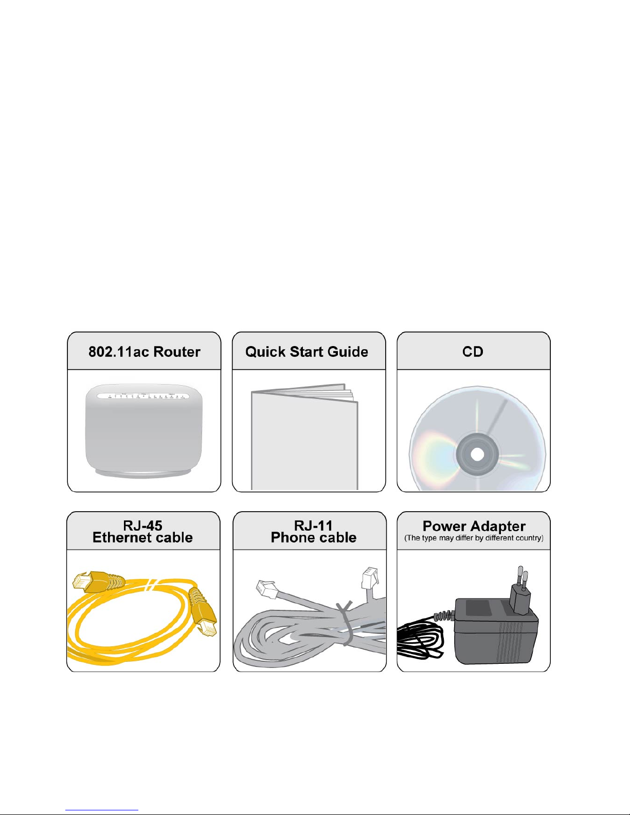
Package Contents
• BiPAC 8800AXL Dual-band Wireless-AC 1600Mbps ADSL2+ 3G/ 4G LTE Router
• Quick Start Guide
• CD containing the on-line manual
• RJ-45 Cat. 5e STP Ethernet cable
• RJ-11 telephone cable
• Power adapter
• Splitter / Micro-filter (Optional)
Page 13

9
Important note for using this router
Warning
1. Do not use the router in high humidity or high temperatures.
2. Do not use the same power source for the router as other equipment.
3. Do not open or repair the case yourself. If the router is too hot, turn off the power
immediately and have it repaired at a qualified service center.
4. Avoid using this product and all accessories outdoors.
Attention
1. Place the router on a stable surface.
2. Only use the power adapter that comes with the package. Using a different voltage rating
power adapter may damage the router.
Page 14

10
Device Description
The Front LEDs
Page 15

11
LED Status Meaning
Red
Boot failure or in emergency mode
Power
Green
System ready
Green Successfully connected to a LAN device (PC, switch, etc).
Ethernet Port 1-4
Blinking Data being transmitted/received
Green Wireless connection established
Wireless
Green blinking Sending/receiving data
Green blinking WPS configuration being in progress
WPS
Off WPS process completed or WPS is off
USB 1-2
Green Successfully connected to a USB device
Green
Successfully connected to a WAN device (Fibre /Cable/
xDSL modem, etc).
EWAN(Ethernet#5)
Blinking Data being transmitted/received
Green Blinking DSL synchronizing or waiting for DSL synchronizing
Green Successfully connected to a DSLAM (Line Sync).
DSL
Off DSL cable unplugged
Red Obtaining IP failure
Green Having obtained an IP address successfully
Internet
Off
Router in bridge mode or DSL connection not present.
Page 16
12
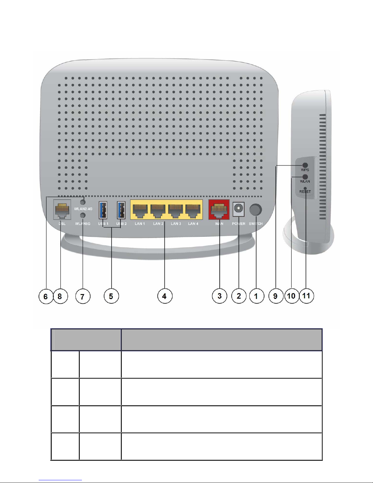
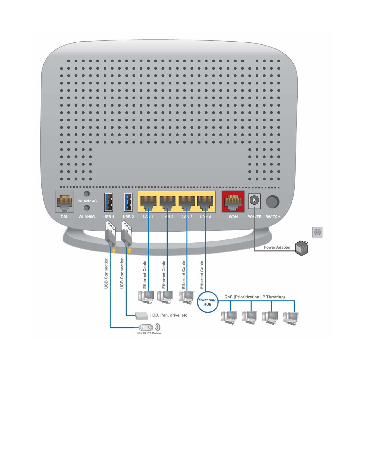
The Rear Ports
Port Meaning
1
Power Switch
Power ON / OFF switch.
2 Power
Connect the supplied power adapter to this jack.
3
WAN
(Ethernet#5)
Connect this port to the fibre/ xDSL/ Cable modem with a UTP Ethernet cable (Cat-5
or Cat-5e).
Note: Port #5 can be configured as an Ethernet Interface for normal LAN use
4 Ethernet 1-4
Connect a UTP Ethernet cable (Cat-5 or Cat-5e) to one of the four LAN ports when
connecting to a PC or an office/home network of 10Mbps /100Mbps /1000Mbps.
Page 17

13
5 USB1-2
Connect the USB device (Printer, USB 2.0 storage, 3G/LTE 3G USB modem) to this
port.
6 WLAN2.4G
Press more than 2 seconds to switch on/off wireless2.4G.
7 WLAN5G
Press more than 2 seconds to switch on/off wireless 5G.
8 DSL
Connect this port to the DSL network with the RJ-11 cable (telephone) provided.
9 WPS
Push WPS button to trigger Wi-Fi Protected Setup function.
10 WLAN
Press WLAN button more than 2 seconds to switch on/off the whole wireless
connectivity, including wireless 2.4G and wireless 5G. Pease Note that the action is
based the status of wireless 2.4G, if now the wireless 2.4G is on, then you press the
WLAN button more than 2 seconds to switch off both wireless mode.
11 RESET
After the device is powered on, press it 5 seconds or above: to restore to factory
default settings (this is used when you cannot login to the router, e.g. forgot the
password)
Page 18

14
Cabling
One of the most common causes of problems is bad cabling or ADSL line(s). Make sure that all
connected devices are turned on. On the front panel of your router is a bank of LEDs. Verify that the
LAN Link and ADSL line LEDs are all lit. If they are not, verify if you are using the proper cables. If
the error persists, you may have a hardware problem. In this case, you should contact technical
support.
Make sure you have a line filter with all devices (e.g. telephones, fax machines, analogue modems)
connected to the same telephone line and the wall socket (unless you are using a Central Splitter or
Central Filter installed by a qualified and licensed electrician), and ensure that all line filters are
correctly installed and the right way around. Missing line filters or line filters installed the wrong way
around can cause problems with your ADSL connection, including causing frequent disconnections.
If you have a back-to-base alarm system you should contact your security provider for a technician
to make any necessary changes.
Page 19

15
Chapter 3: Basic Installation
The router can be configured through your web browser. A web browser is included as a standard
application in the following operating systems: Linux, Mac OS / Windows 8, Windows 7 / 98 / NT /
2000 / XP / Me / Vista, etc. The product provides an easy and user-friendly interface for
configuration.
Please check your PC network components. The TCP/IP protocol stack and Ethernet network
adapter must be installed. If not, please refer to your Windows-related or other operating system
manuals.
There are ways to connect the router, either through an external repeater hub or connect directly
to your PCs. However, make sure that your PCs have an Ethernet interface installed properly prior
to connecting the router device. You ought to configure your PCs to obtain an IP address through
a DHCP server or a fixed IP address that must be in the same subnet as the router. The default IP
address of the router is 192.168.1.254 and the subnet mask is 255.255.255.0 (i.e. any attached PC
must be in the same subnet, and have an IP address in the range of 192.168.1.1 to 192.168.1.253).
The best and easiest way is to configure the PC to get an IP address automatically from the router
using DHCP. If you encounter any problem accessing the router web interface it is advisable to
uninstall your firewall program on your PCs, as they can cause problems accessing the IP address
of the router. Users should make their own decisions on what is best to protect their network.
Please follow the following steps to configure your PC network environment.
Any TCP/IP capable workstation can be used to communicate with or through this router. To
configure other types of workstations, please consult your manufacturer documentation.
Page 20
16
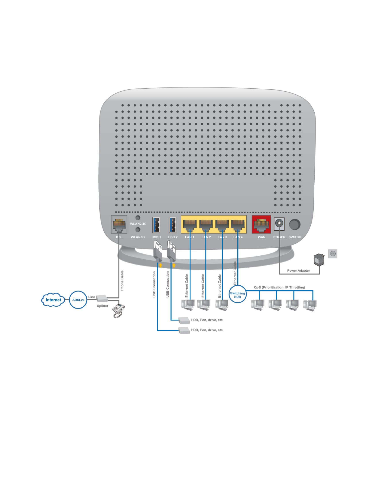
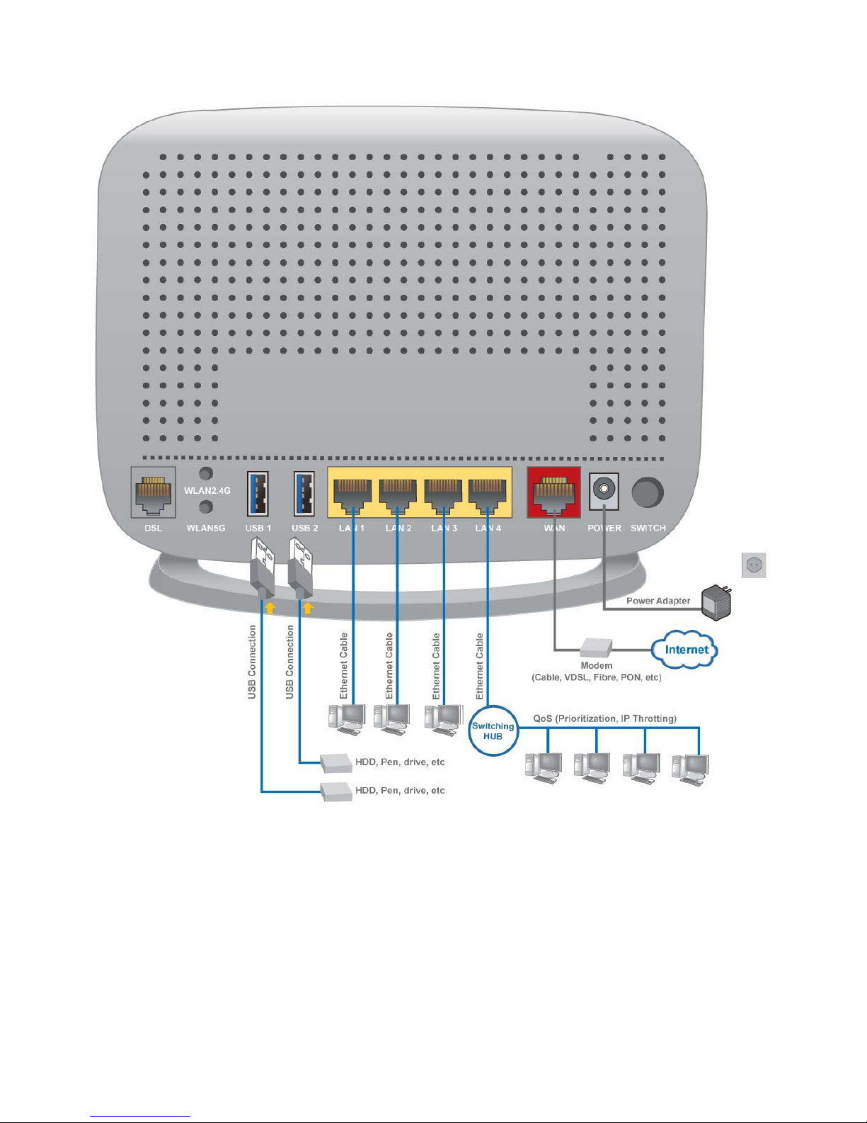
Connecting Your Router
Users can connect the ADSL2+ router as the following.
DSL Router mode:
Page 21
17
Broadband Router mode:
Page 22
18
3G/LTE Router mode
Page 23
19
Network Configuration
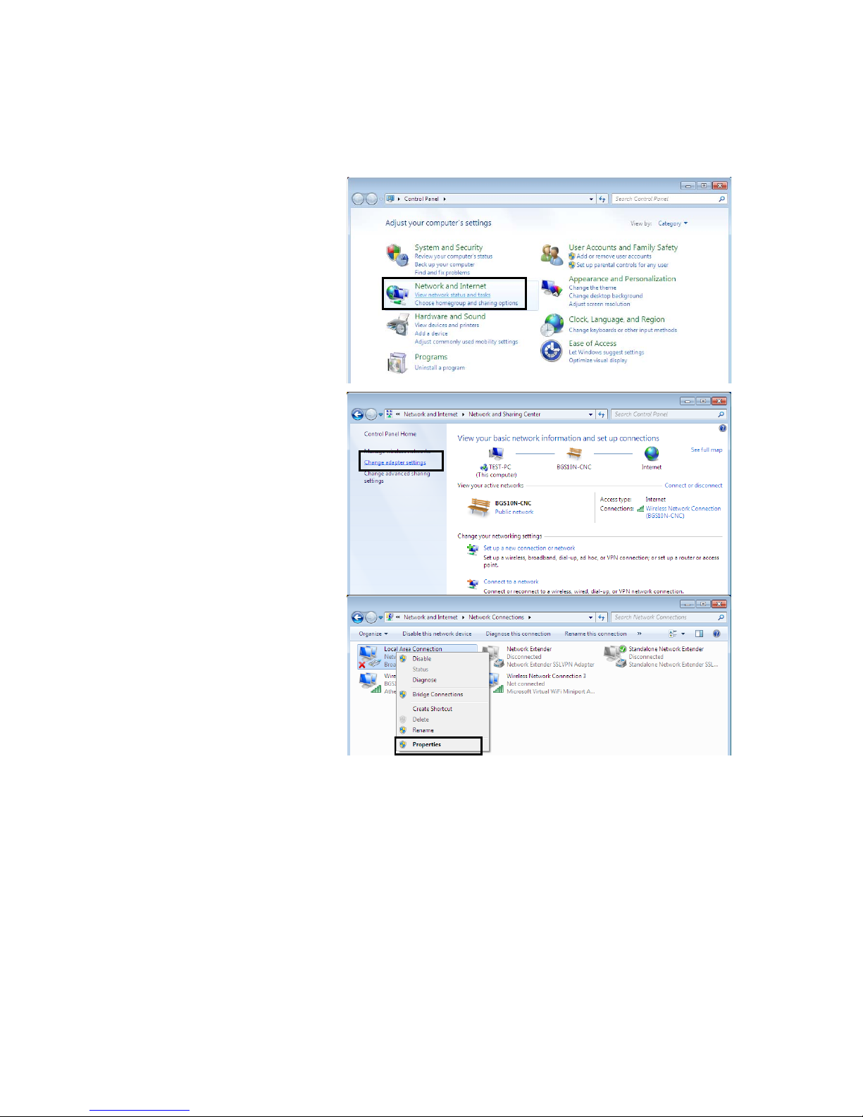
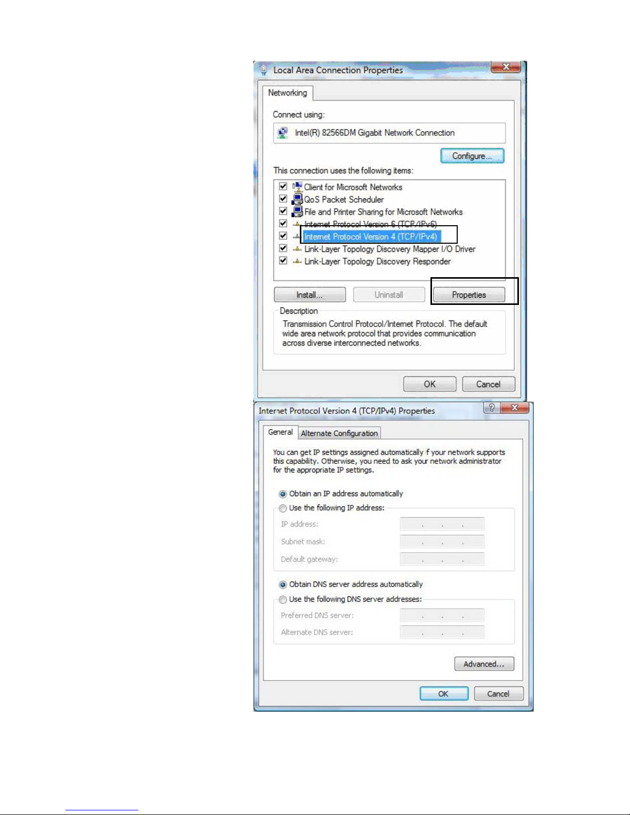
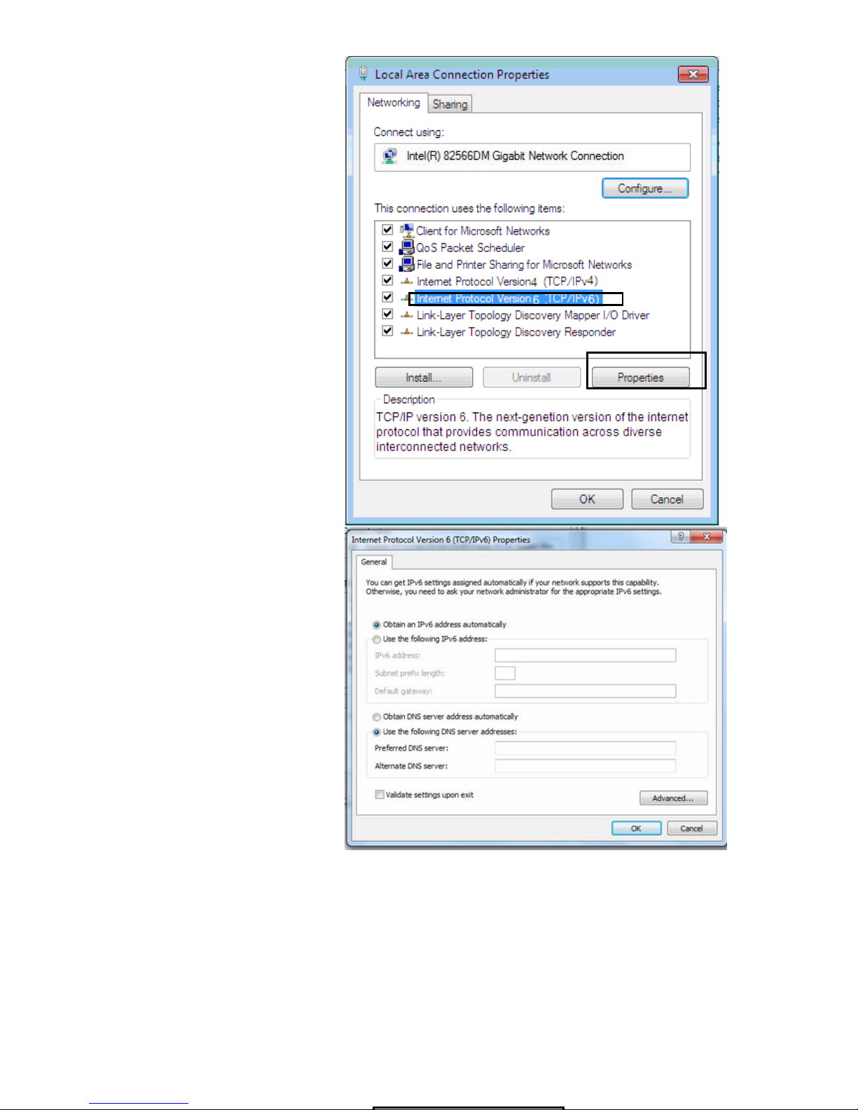
Configuring a PC in Windows 7/ 8
1. Go to Start. Click on Control
Panel.
Then click on Network and
Internet.
2. When the Network and Sharing
Center window pops up, select
and click on Change adapter
settings on the left window
panel.
3. Select the Local Area
Connection, and right click the
icon to select Properties.
Page 24

20
IPv4:
4. Select Internet Protocol
Version 4 (TCP/IPv4) then click
Properties
5. In the TCP/IPv4 properties
window, select the Obtain an IP
address automatically and
Obtain DNS Server address
automatically radio buttons.
Then click OK to exit the setting.
6. Click OK again in the Local
Area Connection Properties
window to apply the new
configuration.
Page 25
21
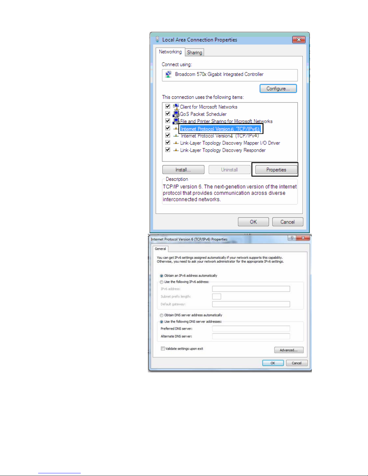
IPv6:
4. Select Internet Protocol
Version 6 (TCP/IPv6) then click
Properties
5. In the TCP/IPv6 properties
window, select the Obtain an
IPv6 address automatically
and Obtain DNS Server
address automatically radio
buttons. Then click OK to exit
the setting.
6. Click OK again in the Local
Area Connection Properties
window to apply the new
configuration.
Page 26
22
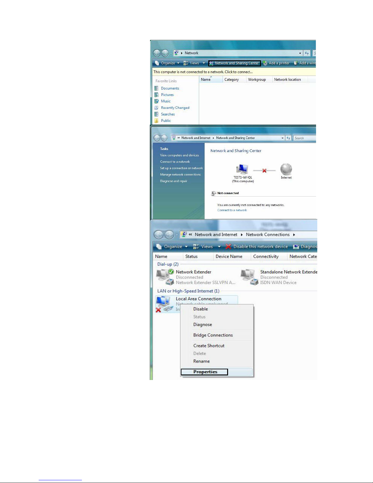
Configuring a PC in Windows Vista
1. Go to Start. Click on Network.
2. Then click on Network and
Sharing Center at the top bar.
3. When the Network and Sharing
Center window pops up, select
and click on Manage network
connections on the left window
pane.
4. Select the Local Area
Connection, and right click the
icon to select Properties.
Page 27
23
IPv4:
5. Select Internet Protocol
Version 4 (TCP/IPv4) then click
Properties.
6. In the TCP/IPv4 properties
window, select the Obtain an IP
address automatically and
Obtain DNS Server address
automatically radio buttons.
Then click OK to exit the setting.
7. Click OK again in the Local Area
Connection Properties window
to apply the new configuration.
Page 28
24
IPv6:
8. Select Internet Protocol
Version 6 (TCP/IPv6) then click
Properties.
9. In the TCP/IPv6 properties
window, select the Obtain an
IPv6 address automatically and
Obtain DNS Server address
automatically radio buttons.
Then click OK to exit the setting.
10. Click OK again in the Local Area
Connection Properties window
to apply the new configuration.
Page 29
25
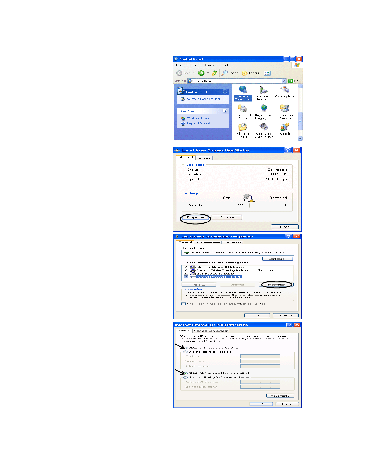
Configuring a PC in Windows XP
IPv4:
1. Go to Start / Control Panel (in Classic
View). In the Control Panel, double-click
on Network Connections
2. Double-click Local Area Connection.
3. In the Local Area Connection Status
window, click Properties.
4. Select Internet Protocol (TCP/IP) and
click Properties.
5. Select the Obtain an IP address
automatically and the Obtain DNS
server address automatically radio
buttons.
6. Click OK to finish the configuration.
Page 30
26
IPv6:
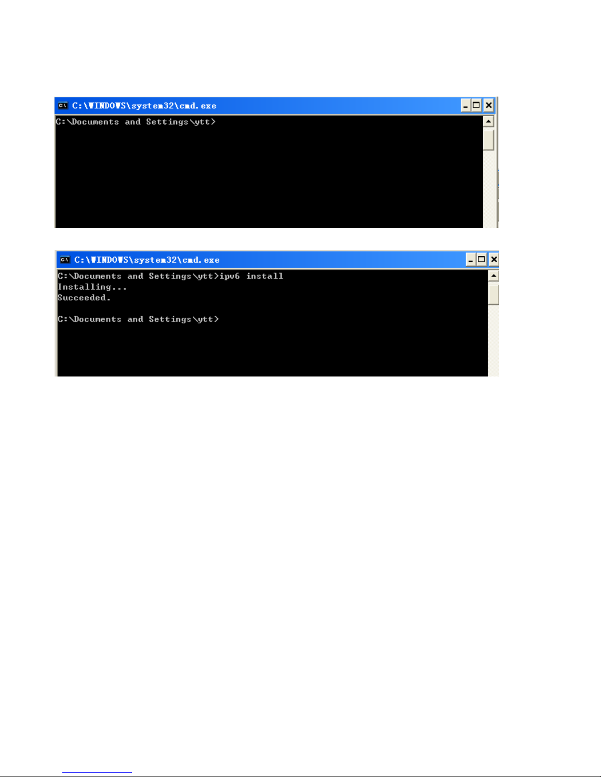
IPv6 is supported by Windows XP, but you should install it first.
Act as shown below:
1. On the desktop, Click Start > Run, type cmd, then press Enter key in the keyboard, the following screen
appears.
2. Key in command ipv6 install
Configuration is OK now, you can test whether it works ok.
Page 31

27
Configuring a PC in Windows 2000
1. Go to Start > Settings > Control Panel.
In the Control Panel, double-click on Network
and Dial-up Connections.
2. Double-click Local Area Connection.
3. In the Local Area Connection Status
window click Properties.
4. Select Internet Protocol (TCP/IP) and
click Properties.
5. Select the Obtain an IP address
automatically and the Obtain DNS server
address automatically radio buttons.
6. Click OK to finish the configuration.
Page 32

28
Configuring a PC in Windows 95/98/Me
1. Go to Start > Settings > Control Panel.
In the Control Panel, double-click on
Network and choose the Configuration tab.
2. Select TCP/IP > NE2000 Compatible, or
the name of your Network Interface Card (NIC)
in your PC.
3. Select the Obtain an IP address
automatically radio button.
4. Then select the DNS Configuration tab.
5. Select the Disable DNS radio button
and click OK to finish the configuration.
Page 33

29
Configuring a PC in Windows NT4.0
1. Go to Start > Settings > Control Panel.
In the Control Panel, double-click on Network
and choose the Protocols tab.
2. Select TCP/IP Protocol and click Properties.
3. Select the Obtain an IP address from a
DHCP server radio button and click OK.
Page 34

30
Factory Default Settings
Before configuring your router, you need to know the following default settings.
Web Interface (Username and Password)
Three user levels are provided by this router, namely Administrator, Remote and Local
respectively. See Access Control .
Administrator
Username: admin
Password: admin
Local
Username: user
Password: user
Remote
Username: support
Password: support
Attention
If you have forgotten the username and/or password of the router, you can restore the device
to its default setting by pressing the Reset Button more than 5 seconds.
Device LAN IPv4 settings
IPv4 Address: 192.168.1.254
Subnet Mask: 255.255.255.0
Device LAN IPv6 settings
IPv6 Address / prefix: Default is a link-local address and is different from each other as MAC
address is different from one to one. For example: fe80:0000:0000:0000:0204:edff:fe01:0001 / 64,
the prefix initiates by fe80::
DHCP server for IPv4
DHCP server is enabled.
Start IP Address: 192.168.1.1
IP pool counts: 20
Page 35

31
LAN and WAN Port Addresses
The parameters of LAN and WAN ports are pre-set in the factory. The default values are shown in
the table.
IPv4
LAN Port
WAN Port
IPv4 address 192.168.1.254
Subnet Mask 255.255.255.0
DHCP server function Enabled
IP addresses for
distribution to PCs
20 IP addresses continuing
from 192.168.1.1 through
192.168.1.19
The PPPoE function is
enabled to automatically get
the WAN port configuration
from the ISP.
IPv6
LAN Port
WAN Port
IPv6 address/prefix Default is a link-local address and is
different from each other as MAC
address is different from one to one.
For example :
fe80::204:edff:fe01:1/64,
the prefix initiates by fe80::
DHCP server function Enabled
The PPPoE function is
enabled to automatically get
the WAN port configuration
from the ISP.
Page 36

32
Information from your ISP
Before configuring this device, you have to check with your ISP (Internet Service Provider) to find
out what kind of service is provided.
Gather the information as illustrated in the following table and keep it for reference.
PPPoE(RFC2516)
VPI/VCI, VC / LLC-based multiplexing, Username, Password, Service
Name, and Domain Name System (DNS) IP address (it can be
automatically assigned by your ISP when you connect or be set manually).
PPPoA(RFC2364)
VPI/VCI, VC / LLC-based multiplexing, Username, Password and Domain
Name System (DNS) IP address (it can be automatically assigned by your
ISP when you connect or be set manually).
DHCP Client
VPI/VCI, VC / LLC-based multiplexing, Domain Name System (DNS) IP
address (it can be automatically assigned by your ISP when you connect or
be set manually).
IPoA(RFC1577)
VPI/VCI, VC / LLC-based multiplexing, IP address, Subnet mask, Gateway
address, and Domain Name System (DNS) IP address (it is a fixed IP
address).
Pure Bridge
VPI/VCI, VC / LLC-based multiplexing to use Bridged Mode.
Page 37

33
Easy Sign On (EZSO)
This special feature makes it easier for you to configure your router so that you can connect to the
internet in a matter of seconds without having to logon to the router GUI for any detail configuration.
This configuration method is usually auto initiated if user is to connect to the internet via Billion's
router for the first time.
After setting up the router with all the appropriate cables plugged-in, open up your IE browser, the
EZSO WEB GUI will automatically pop up and request that you enter some basic information that
you have obtained from your ISP. By following the instructions given carefully and through the
information you provide, the router will be configured in no time and you will find yourself surfing the
internet sooner than you realize.
EZSO window pops up:
Step1: Set the administration password.
Step 2: Set the Time Zone.
Step 3: Configure the WAN interface.
DSL mode
Here take ADSL for example.
Before configuring with DSL mode, please confirm you have correctly connected the DSL line, and it
is now synchronized.
1. Select DSL, press Continue to go on to next step, press “Done” to quit the setting. Then choose
Manually or IPTV (simplifying the WAN configuration and Jump to step 4 if WAN is successfully
configured).
Page 38

34
2. Enter the username, password from your ISP, for IP and DNS settings; also refer to your ISP.
Here IPv6 service is enabled by default.
If the DLS line doesn’t synchronize, the page will pop up warning of the DSL connection failure.
3. Wait while the device is configured (DSL synchronized).
4. WAN port configuration is success and next to wireless, if you want skip wireless setting, click
Done.
Click Done, web configuration will be loaded, you will enter the web configuration page.
Page 39

35
5. After the configuration is successful, click Next to Wireless button and you may proceed to
configure the Wireless setting. The 8800AXL supports dual-band wireless, here you can set to
activate wireless on which band or both and set the SSID and encryption Key. (1. Leave it empty to
disable the wireless security; 2. Fill in the Key, and the encryption mode will be WPA2-PSK/AES).
6. Continue to set 5GHz wireless.
7. Success in configuring the EZSO.
Page 40

36
Click link 192.168.1.254, it will lead you to the following page.
Page 41

37
Ethernet mode
1. Select Ethernet, press Continue to go on to next step.
2. Enter the username, password from your ISP, for IP and DNS settings, also refer to your ISP.
Here IPv6 service is enabled by default.
3. Wait while the device is configured.
4. WAN port configuration is success.
Click Done, web configuration will be loaded, you will enter the web configuration page.
Page 42

38
5. After the configuration is successful, click Next to Wireless button and you may proceed to
configure the Wireless setting. The 8800AXL supports dual-band wireless, here you can set to
activate wireless on which band or both and set the SSID and encryption Key (1. Leave it empty to
disable the wireless security; 2. Fill in the Key, and the encryption mode will be WPA2-PSK/AES).
6. Continue to set 5GHz wireless.
7. Success in configuring the EZSO.
Page 43

39
Click 192.168.1.254, it will lead you to the following page.
Page 44

40
3G/LTE
1. Select 3G/LTE, press Continue to go on to next step.
2. Enter the APN, username, password from your ISP, for settings about Authentication method, PIN,
etc, also refer to your ISP.
3. Wait while the device is configured.
4. WAN port configuration is success.
Click Done, web configuration will be loaded, you will enter the web configuration page.
Page 45

41
5. After the configuration is successful, click Next to Wireless button and you may proceed to
configure the Wireless setting. The 8800AXL supports dual-band wireless, here you can set to
activate wireless on which band or both and set the SSID and encryption Key (1. Leave it empty to
disable the wireless security; 2. Fill in the Key, and the encryption mode will be WPA2-PSK/AES).
6. Continue to set 5GHz wireless.
7. Success in configuring the EZSO.
Page 46

42
Click 192.168.1.254, it will lead you to the following page.
Page 47

43
Chapter 4: Configuration
Configuration via Web Interface
Open your web browser; enter the IP address of your router, which by default is 192.168.1.254, and
click or press ‘Enter’ key on the keyboard, a login prompt window will appear. The default root
username and password are “admin” and “admin” respectively.
Congratulations! You are now successfully logged in to the ADSl2+ Router!
Page 48

44
Once you have logged on to your BiPAC 8800AXL Router via your web browser, you can begin to
set it up according to your requirements. On the configuration homepage, the left navigation pane
links you directly to the setup pages, which include:
Status (Summary, WAN, Statistics, Bandwidth Usage, 3G/LTE Status, Route, ARP, DHCP, Log)
Quick Start (Quick Start)
Configuration (LAN, Wireless 2.4G(wl0), Wireless 5G(wl1), WAN, System, USB, IP Tunnel,
Security, Quality of Service, NAT, Wake On LAN)
Advanced Setup (Routing, DNS, Static ARP, UPnP, Certificate, Multicast, Management,
Diagnostics)
Page 49

45
Status
This Section gives users an easy access to the information about the working router and access to
view the current status of the router. Here Summary, WAN, Statistics, Bandwidth Usage,
3G/LTE Status, Route, ARP, DHCP and Log subsections are included.
Summary
Page 50

46
The basic information about the device is provided here (the following is a configured
screenshots to let users understand clearly).
Device Information
Model Name: Displays the model name.
Host Name: Displays the name of the router.
System Up-Time: Displays the elapsed time since the device is on.
Date/Time: Displays the current exact date and time. Sync button is to synchronize the
Date/Time with your PC time without regard to connecting to internet or not.
Software Version: Firmware version.
LAN IPv4 Address: Displays the LAN IPv4 address.
LAN IPv6 Address: Displays the LAN IPv6 address. Default is a Link-Local address, but
when connects to ISP, it will display the Global Address, like above figure.
MAC Address: Displays the MAC address.
DSL PHY and Driver Version: Display DSL PHY and Driver version.
Wireless Driver Version: Displays wireless driver version.
WAN
Line Rate – Upstream (Kbps): Displays Upstream line Rate in Kbps.
Line Rate – Downstream (Kbps): Displays Downstream line Rate in Kbps.
Default Gateway/IPv4 Address: Display Default Gateway and the IPv4 address.
Connection Time: Displays the elapsed time since ADSL connection is up.
Primary DNS Server: Displays IPV4 address of Primary DNS Server.
Secondary DNS Server: Displays IPV4 address of Secondary DNS Server.
Default IPv6 Gateway/IPv6 Address: Display the IPv6 Gateway and the obtained IPv6
address.
Page 51

47
WAN
This table displays the information of the WAN connections, users can turn here for WAN connection
information.
Interface: The WAN connection interface.
Description: The description of this connection.
Type: The protocol used by this connection.
Status: To disconnect or connect the link.
Connection Time: The WAN connection time since WAN is up.
IPv4 Address: The WAN IPv4 Address the device obtained.
IPv6 Address: The WAN IPv6 Address the device obtained.
DNS: The DNS address the device obtained.
Page 52

48
Statistics
LAN
The table shows the statistics of LAN.
Note: P5 can be configured as EWAN, and when the device is in EWAN profile, there is no
P5/EWAN interface as P5 is working as a WAN port.
(DSL)
(EWAN)
Interface: List each LAN interface. P1-P4 indicates the four LAN interfaces.
Bytes: Display the Received and Transmitted traffic statistics in Bytes.
Packets: Display the Received and Transmitted traffic statistics in Packets.
Errors: Display the statistics of errors arising in Receiving or Transmitting data.
Drops: Display the statistics of drops arising in Receiving or Transmitting data.
Reset: Press this button to refresh the statistics.
Page 53

49
WAN Service
The table shows the statistics of WAN.
Interface: Display the connection interface.
Description: the description for the connection.
Bytes: Display the WAN Received and Transmitted traffic statistics in Bytes.
Packets: Display the WAN Received and Transmitted traffic statistics in Packests.
Errors: Display the statistics of errors arising in Receiving or Transmitting data.
Drops: Display the statistics of drops arising in Receiving or Transmitting data.
Reset: Press this button to refresh the statistics.
xTM
The Statistics-xTM screen displays all the xTM statistics
Port Number: Shows number of the port for xTM.
In Octets: Number of received octets over the interface.
Out Octets: Number of transmitted octets over the interface.
In Packets: Number of received packets over the interface.
Out Packets: Number of transmitted packets over the interface.
In OAM Cells: Number of OAM cells received.
Out OAM Cells: Number of OAM cells transmitted.
In ASM Cells: Number of ASM cells received.
Out ASM Cells: Number of ASM cells transmitted.
In Packet Errors: Number of received packets with errors.
In Cell Errors: Number of received cells with errors.
Reset: Click to reset the statistics.
Page 54

50
xDSL
Mode: Modulation protocol, including G.dmt, G.lite, T1.413, ADSL2, AnnexL, ADSL2+ and AnnexM.
Traffic Type: Transfer mode, here supports ATM and PTM.
Status: Show the status of DSL link.
Link Power State: Show link output power state.
Line Coding (Trellis): Trellis on/off.
Page 55

51
SNR Margin (dB): Show the Signal to Noise Ratio(SNR) margin.
Attenuation (dB): This is estimate of average loop attenuation of signal.
Output Power (dBm): Show the output power.
Attainable Rate (Kbps): The sync rate you would obtain.
Rate (Kbps): Show the downstream and upstream rate in Kbps.
MSGc (#of bytes in overhead channel message): The number of bytes in overhead channel
message.
B (# of bytes in Mux Data Frame): The number of bytes in Mux Data frame.
M (# of Mux Data Frames in FEC Data Frame): The number of Mux Data frames in FEC frame.
T (Mux Data Frames over sync bytes): The number of Mux Data frames over all the sync bytes.
R (# of check bytes in FEC Data Frame): The number of check bytes in FEC frame.
S (ratio of FEC over PMD Data Frame length): The ratio of FEC over PMD Data frame length
L (# of bits in PMD Data Frame): The number of bit in PMD Data frame
D (interleaver depth): Show the interleaver depth.
Delay (msec): Show the delay time in msec.
INP (DMT symbol): Show the DMT symbol.
Super Frames: The total number of super frames.
Super Frame Errors: the total number of super frame errors.
RS Words: Total number of Reed-Solomon code errors.
RS Correctable Errors: Total number of RS with correctable errors.
RS Uncorrectable Errors: Total number of RS words with uncorrectable errors.
HEC Errors: Total number of Header Error Checksum errors.
OCD Errors: Total number of out-of-cell Delineation errors.
LCD Errors: Total number of Loss of Cell Delineation.
Total Cells: Total number of cells.
Data Cells: Total number of data cells.
Bit Errors: Total number of bit errors.
Total ES: Total Number of Errored Seconds.
Total SES: Total Number of Severely Errored Seconds.
Total UAS: Total Number of Unavailable Seconds.
xDSL BER Test: Click this button to start a bit Error Rate Test. The ADSL Bit Error Rate (BER) test
determines the quality of the ADSL connection. The test is done by transferring idle cells containing
a known pattern and comparing the received data with this known pattern to check for any errors.
Page 56

52
Select the Tested Time(sec), press Start to start test.
When it is OK, the following test result window will appear. You can view the quality of ADSL
connection. Here the connection is OK.
Reset: Click this button to reset the statistics.
Page 57

53
Bandwidth Usage
Bandwidth Usage provides users direct view of bandwidth usage with simple diagram. Bandwidth
usage shows the use of the bandwidth from two angles: Transmitted and Received, giving users a
clear idea of the usage.
LAN
Note: P5 can be configured as EWAN, and when the device is in EWAN profile, there is no
P5/EWAN interface as P5 is working as a WAN port.
(EWAN)
Press View LAN Transmitted button to change the diagram to the statistics from a Received Bytes
of view. (Note: means Ethernet port #3, and the traffic information of the port #3 is identified
with green, the same color with P3 in the diagram; other ports all take the same mechanism.)
Page 58

54
When you press View WAN Traffic concurrently button, the WAN Bandwidth Usage pops up so
that users can view the WAN traffic concurrently.
Page 59

55
WAN Service
Press View WAN Transmitted button to change the diagram to the statistics from a Received Bytes
of view.
Page 60

56
Press View LAN Traffic concurrently button to directly switch to the LAN Bandwidth Usage page
to view the LAN traffic concurrently.
Page 61

57
3G/LTE Status
Status: The current status of the 3G/LTE card.
Signal Strength: The signal strength bar indicates current 3G signal strength.
Network Name: The network name that the device is connected to.
Network Mode: The current operation mode for 3G/LTE card, it depends on service provider and
card’s limitation, GSM or UMTS.
Card Name: The name of the 3G/LTE card.
Card Firmware: The current firmware for the 3G/LTE card.
Page 62

58
Route
Destination: The IP address of destination network.
Gateway: The IP address of the gateway this route uses.
Subnet Mask: The destination subnet mask.
Flag: Show the status of the route.
U: Show the route is activated or enabled.
H (host): destination is host not the subnet.
G: Show that the outside gateway is needed to forward packets in this route.
R: Show that the route is reinstated from dynamic routing.
D: Show that the route is dynamically installed by daemon or redirecting.
M: Show the route is modified from routing daemon or redirect.
Metric: Display the number of hops counted as the Metric of the route.
Service: Display the service that this route uses.
Interface: Display the existing interface this route uses.
Page 63

59
ARP
This section displays the router’s ARP (Address Resolution Protocol) Table, which shows the
mapping of Internet (IP) addresses to Ethernet (MAC) addresses. This is useful as a quick way of
determining the MAC address of the network interface of your PCs to use with the router’s Security
– MAC Filtering function. Here IPv6 Neighbor Table, listed with IPv6 address-MAC mapping, is
supported.
ARP table
IP Address: Shows the IP Address of the device that the MAC address maps to.
Flag: Shows the current status of the ARP entries.
Complete: the route resolving is processing well.
M(Marked as permanent entry): the route is permanent.
P (publish entry): publish this route item.
MAC Address: Shows the MAC address that is corresponded to the IP address of the device it is
mapped to.
Device: here refers to the physical interface, it is a concept to identify Clients from LAN or WAN. For
example, the Clients in LAN, here displays “br0”.
Mark: Show clearly the SSID (WLAN) the device is in.
Neighbor Cache Table
IPv6 address: Shows the IPv6 Address of the device that the MAC address maps to.
MAC Address: Shows the MAC address that is corresponded to the IPv6 address of the device it is
mapped to.
Device: here refers to the physical interface, it is a concept to identify Clients from LAN or WAN. For
example, the Clients in LAN, here displays “br0”.
Mark: Show clearly the SSID (WLAN) the device is in.
Page 64

60
DHCP
The DHCP Table lists the DHCP lease information for all IP addresses assigned by the DHCP server
in the device.
Host Name: The Host Name of DHCP client.
MAC Address: The MAC Address of internal DHCP client host.
IP Address: The IP address which is assigned to the host with this MAC address.
Expires in: Show the remaining time after registration.
Mark: Show clearly the SSID (WLAN) the device is in.
Page 65

61
Log
System Log
Display system logs accumulated up to the present time. You can trace historical information with
this function. And the log policy can be configured in Configure Log section.
Refresh: Click to update the system log.
Clear: Click to clear the current log from the screen.
Page 66

62
Security Log
Security log displays the message logged about security, like filter messages and some firewall
message. You can turn to IP Filtering Outgoing
, IP Filtering Incoming, URL Filter to determine if you
want to log this information. Also you can turn to Configure Log section below to determine the level
to log the message. You can use this to track potential threats to your system and network.
Refresh: Click to update the system log.
Clear: Click to clear the current log from the screen.
Page 67

63
Quick Start
Quick Start
This part allows you to quickly configure and connect your router to internet.
DSL mode
Here take ADSL for example.
1. Select DSL, press Continue to go on to next step. Choose Manually or IPTV (simplifying the
WAN configuration and Jump to step 4 if WAN is successfully configured).
2. Enter the username, password from your ISP, for IP and DNS settings; also refer to your ISP.
Here IPv6 service is enabled by default.
Page 68

64
If the DLS line is not synchronized, the page will pop up warning of the DSL connection failure.
3. Wait while the device is configured.
4. WAN port configuration is successful.
5. After the configuration is successful, click Next to Wireless button and you may proceed to
configure the Wireless setting. The 8800AXL supports dual-band wireless, here you can set to
activate wireless on which band or both and set the SSID and encryption Key (1. Leave it empty to
disable the wireless security; 2. Fill in the Key, and the encryption mode will be WPA2-PSK/AES).
6. Continue to set 5GHz wireless.
Page 69

65
7. Success.
If Quick Start is finished, user can turn to Status > Summary to see the basic information.
Page 70

66
Ethernet mode
1. Select Ethernet, press Continue to go on to next step.
2. Enter the username, password from your ISP, for IP and DNS settings; also refer to your ISP.
Here IPv6 service is enabled by default.
3. Wait while the device is configured.
4. WAN port configuration is successful.
Page 71

67
5. After the configuration is successful, click Next to Wireless button and you may proceed to
configure the Wireless setting. The device supports dual-band wireless connections, in Quick Start
part, users can only enable or disable the wireless on the band and the exact SSID and encryption
Key (1. Leave it empty to disable the wireless security; 2. Fill in the Key, and the encryption mode
will be WPA2-PSK/AES). For detail setting, please go to the Wireless part in this Manual.
6. Continue to set 5GHz wireless.
7. Success.
Page 72

68
3G/LTE
1. Select 3G/LTE, press Continue to go on to next step.
2. Select the 3G mode, and enter the APN, username, password from your ISP; and check with your
ISP with the authentication method setting.
3. Wait while the device is configured.
4. WAN port configuration is successful.
Page 73

69
5. After the configuration is successful, click Next to Wireless button and you may proceed to
configure the Wireless setting. The device supports dual-band wireless connections, in Quick Start
part, users can only enable or disable the wireless on the band and the exact SSID and encryption
Key (1. Leave it empty to disable the wireless security; 2. Fill in the Key, and the encryption mode
will be WPA2-PSK/AES). For detail setting, please go to the Wireless part in this Manual.
6. Continue to set 5GHz wireless.
Page 74

70
7. Success.
If Quick Start is finished, user can turn to Status > Summary to see the basic information.
Page 75

71
Configuration
When you click this item, the column will expand to display the sub-items that will allow you to further
configure your router.
LAN, Wireless 2.4G (wl0), Wireless 5G (wl1), WAN, System, USB, IP Tunnel, Security, Quality
of Service, NAT and Wake On LAN.
The function of each configuration sub-item is described in the following sections.
Page 76

72
LAN - Local Area Network
A Local Area Network (LAN) is a shared communication system network where many computers
are connected. This type of network is area defined and is usually limited to a confined region within
a building.
Ethernet
Parameters
Group Name: This refers to the group you set in Interface Grouping section; you can set the
parameters for the specific group. Select the group via the drop-down box. For more information
please refer to Interface Grouping
of this manual.
IP address: the IP address of the router. Default is 192.168.1.254.
Subnet Mask: the default Subnet mask on the router.
IGMP Snooping: Enable or disable the IGMP Snooping function. Without IGMP snooping,
multicast traffic is treated in the same manner as broadcast traffic - that is, it is forwarded to all
ports. With IGMP snooping, multicast traffic of a group is only forwarded to ports that have
members of that group.”
When enabled, you will see two modes:
Standard Mode: In standard mode, multicast traffic will flood to all bridge ports when no
client subscribes to a multicast group.
Blocking Mode: In blocking mode, the multicast data will be blocked when there are no
client subscribes to a multicast group, it won’t flood to the bridge ports.
LAN side firewall: Enable to drop all traffic from the specified LAN group interface. After activating it,
Page 77

73
all incoming packets by default will be dropped, and the user on the specified LAN group interface
can't access CPE anymore. But, you can still access the internet service. If user wants to manage
the CPE, please turn to IP Filtering Incoming
to add the allowing rules. Note that all incoming
packets by default will be dropped if the LAN side firewall is enabled and user cannot manage this
CPE from the specified LAN group.
DHCP Server
You can disable or enable the DHCP (Dynamic Host Configuration Protocol) server or enable the
router’s DHCP relay functions. The DHCP protocol allows your router to dynamically assign IP
addresses to PCs on your network if they are configured to obtain IP addresses automatically.
Disable
Disable the DHCP Server function.
Enable
Enable the DHCP function, enter the information wanted. Here as default.
Start IP Address: The start IP address of the range the DHCP Server used to assign to the Clients.
End IP Address: The end IP address f the range the DHCP Server used to assign to the Clients.
Leased Time (hour): The leased time for each DHCP Client.
Option 66: Click Enable to activate DHCP option 66 for some special devices, like IPTV Set Box.
The devices can get firmware or some special service from the TFTP server. User needs to set the
IP or hostname of the TFTP server.
User Router’s setting as DNS server: Select whether to enable use router’s setting as DNS server,
if enabled, the PCs on the LAN side obtain the router’s setting as DNS server. If disabled, please
specify exactly the primary/secondary DNS server.
Primary/Secondary DNS server: Specify your primary/secondary DNS server for your LAN devices.
DHCP Server Relay
DHCP Server IP Address: Please enter the DHCP Server IP address.
Page 78

74
Static IP List
The specified IP will be assigned to the corresponding MAC Address listed in the following table
when DHCP Server assigns IP Addresses to Clients.
Press Add to the Static IP List.
Enter the MAC Address, IP Address, and then click Apply to confirm your settings. But the IP
assigned should be outside the range of 192.168.1.100-192.168.1.199.
IP Alias
This function allows the creation of multiple virtual IP interfaces on this router. It helps to connect two
or more local networks to the ISP or remote node.
IP Alias: Check whether to enable this function.
IP Address: Specify an IP address on this virtual interface.
Subnet Mask: Specify a subnet mask on this virtual interface.
Click Apply to apply your settings.
Page 79

75
IPv6 Autoconfig
The IPv6 address composes of two parts, the prefix and the interface ID.
There are two ways to dynamically configure IPv6 address on hosts. One is “stateful” configuration,
for example using DHCPv6 (which resembles its counterpart DHCP in IPv4.) In the stateful autoconfiguration model, hosts obtain interface addresses and/or configuration information and
parameters from a DHCPv6 server. The Server maintains a database that keeps track of which
addresses have been assigned to which hosts.
The second way is “stateless” configuration. Stateless auto-configuration requires no manual
configuration of hosts, minimal (if any) configuration of routers, and no additional servers. The
stateless mechanism allows a host to generate its own addresses using a combination of locally
available information (MAC address) and information (prefix) advertised by routers. Routers
advertise prefixes that identify the subnet(s) associated with a link, while hosts generate an
"interface identifier" that uniquely identifies an interface on a subnet. An address is formed by
combining the two. When using stateless configuration, you needn’t configure anything on the client.
Group Name: Here group refers to the group you set in Interface Grouping section, you can set
the parameters for the specific group. Select the group by the drop-down box. For more
information please refer to Interface Grouping of this manual.
Static LAN IPv6 Address Configuration
Interface Address / Prefix Length: Enter the static LAN IPv6 address.
IPv6 LAN application
DHCPv6 Server: Check whether to enable DHCPv6 server.
DHCPv6 Server Type: Select Stateless or Stateful. When DHCPv6 is enabled, this parameter is
Page 80

76
available. Stateless: If selected, the PCs in LAN are configured through RA mode, thus, the PCs in
LAN are configured through RA mode, to obtain the prefix message and generate an address using
a combination of locally available information (MAC address) and information (prefix) advertised by
routers, but they can obtain such information like DNS from DHCPv6 Server. St ateful: if selected,
the PCs in LAN will be configured like in IPv4 mode, thus obtain addresses and DNS information
from DHCPv6 server.
Start interface ID: Enter the start interface ID. The IPv6 address composed of two parts, thus, the
prefix and the interface ID. Interface is like the Host ID compared to IPv4.
End interface ID: Enter the end interface ID.
Note: Interface ID does NOT support ZERO COMPRESSION "::". Please enter the complete
information.
For example: Please enter "0:0:0:2" instead of "::2".
Leased Time (hour): The leased time, similar to leased time in DHCPv4, is a time limit assigned to
clients, when expires, the assigned ID will be recycled and reassigned.
Issue Router Advertisement: Check whether to enable issue Router Advertisement feature. It is to
send Router Advertisement messages periodically.
ULA Prefix Advertisement: Enable this parameter to include the ipv6 ULA address in the RA
messages. ULA, unique local address, is an IPv6 address in the block fc00::/7. It is approximately
the IPv6 counterpart of the IPv4 private address. They are not routable in the global IPv6 Internet.
RADVD Type: The way that ULA prefix is generated.
Randomly Generated
Statically Configured: select to set manually in the following parameters.
Prefix: Set the prefix manually.
Preferred Life Time: The ULA prefix life time. When the time is over, the ULA prefix is invalid any
more, -1 means no limit.
Valid Life Time: It is a time threshold, when the time is over, clients should obtain new IPv6 address
from the router through RA; -1 means to be limitless.
MLD snooping: Similar to IGMP snooping, listens in on the MLD conversation between hosts and
routers by processing MLD packets sent in a multicast network, and it analyzes all MLD packets
between hosts and the connected multicast routers in the network. Without MLD snooping, multicast
traffic is treated in the same manner as broadcast traffic - that is, it is forwarded to all ports. With
MLD snooping, multicast traffic of a group is only forwarded to ports that have members of that
group.
Standard Mode: In standard mode, multicast traffic will flood to all bridge ports when no
client subscribes to a multicast group.
Blocking Mode: In blocking mode, the multicast data will be blocked when there is no
client subscribes to a multicast group, it won’t flood to the bridge ports.
Page 81

77
Stateless and Stateful IPv6 address Configuration
Stateless: Two methods can be carried.
With DHCPv6 disabled, but Issue Router Advertisement Enabled
With this method, the PCs in LAN are configured through RA mode, thus, the PCs in LAN are
configured through RA mode, to obtain the prefix message and generate an address using a
combination of locally available information (MAC address) and information (prefix) advertised by
routers.
With both DHCPv6 and Issue Router Advertisement Enabled
With this method, the PCs’ addresses in LAN are configured like above method, but they can
obtain such information like DNS from DHCPv6 Server.
Page 82

78
Stateful: two methods can be adopted.
With only DHCPv6 enabled
With this method, the PCs’ addresses are configured the same as in IPv4, that is addresses are
assigned by DHCPv6 server.
With both DHCPv6 and Issue Router Advertisement Enabled
With this method, the PCs’ addresses are configured the same like above, and the address
information in RA packets will be neglected.
Page 83

79
Interface Grouping
Interface grouping is a function to group interfaces, known as VLAN. A Virtual LAN, commonly known
as a VLAN, is a group of hosts with the common set of requir ements that communicate as if they were
attached to the same broadcast domain, regardles s of the physical location. A VLAN has the same
attributes as a physical LAN, but it allows for end stations to be grouped together even if they are not
located on the same network switch.
Each group will perform as an independent network. To support this feature, you must create
mapping groups with appropriate LAN and WAN interfaces using the Add button.
(Please Note: P5 can be configured as EWAN, and when the device is in EWAN profile, there is no
P5/EWAN interface as P5 is working as a WAN port.)
Groups Isolation: If enabled, devices in one group are not able to access those in the other group.
Page 84

80
Click Add to add groups.
Group Name: Type a group name.
Grouped WAN Interfaces: Select from the box the WAN interface you want to applied in the group.
Grouped LAN Interfaces: Select the LAN interfaces you want to group as a single group from
Available LAN Interfaces.
Automatically Add Clients with following DHCP Vendor IDs: Enter the DHCP Vendor IDs for
which you want the Clients automatically added into the group. DHCP vendor ID (DHCP 60) is an
Authentication for DHCP Messages.
Click Apply to confirm your settings and your added group will be listed in the Interface Grouping
table below.
Page 85

81
In group "test", P2 and PPP0.1 are grouped in one group, they have their only network , see LAN.
If you want to remove the group, check the box as the following and press Remove.
Note: If you like to automatically add LAN clients to a WAN Interface in the new group add the
DHCP vendor ID string.
By configuring a DHCP vendor ID string any DHCP client request with the specified vendor
ID (DHCP option 60) will be denied an IP address from the local DHCP server.
If a vendor ID is configured for a specific client device, please REBOOT the client device
attached to the modem to allow it to obtain an appropriate IP address.
Each LAN interface can only be added into one group and one WAN interface can only be
used in one group.
Page 86

82
Wireless 2.4G(wl0)
This section provides you ways to configure wireless access. The BiPAC 8800AXL supports
wireless on the 2.4GHz and 5GHz for users. Wl0, operating on 2.4GHz, has sub-items as Basic,
Security, MAC Filter, Wireless Bridge, Advanced, Station Info and Schedule Control here. Wl1,
running on 5GHz supporting Wireless-AC, are to set with the same ways as in Wl0.
Page 87

83
Basic
It let you determine whether to enable Wireless function and set the basic parameters of an AP and
the Virtual APs.
Wireless: Default setting is set to Enable. If you do not have any wireless devices, check the
checkbox again to unselect.
Hide SSID: It is function in which transmits its SSID to the air so that when wireless client searches
for a network, router can then be discovered and recognized. Check the checkbox to determine
whether you want to hide SSID.
Clients Isolation: if you enabled this function, then each of your wireless clients will not be able to
communicate with each other.
Disable WMM Advertise: Stop the router from ‘advertising’ its Wireless Multimedia (WMM)
functionality, which provides basic quality of service for time-sensitive applications (e.g. VoIP, Video).
Check to disable or enable this function.
Wireless multicast Forwarding (WMF): check to enable or disable wireless multicast forwarding.
SSID: The SSID is the unique name of a wireless access point (AP) to be distinguished from another.
For security purpose, change the default wlan-ap-2.4g to a unique ID name to the AP already builtin to the router’s wireless interface. It is case sensitive and must not excess 32 characters. Make
sure your wireless clients have exactly the SSID as the device, in order to get connected to your
network.
Note: SSID is case sensitive and must not exceed 32 characters.
BSSID: Basic Set Service Identifier, it is a local managed IEEE MAC address, and is 48 bits value.
Country: Different countries have different wireless band resources, so you can select the
appropriate Country according to your location.
Max Clients: enter the number of max clients the wireless network can supports,1-16.
Guest/virtual Access Points: A “Virtual Ac cess Point” is a logical entity that exists within a physical
Access Point (AP). When a single physical AP supports multiple “Virtual APs”, each Virtual AP
appears to stations (STAs) to be an independent physical AP, even though only a single physical AP
is present. For example, multiple Virtual APs might exist within a single physical AP, each advertising
a distinct SSID and capability set. Alternatively, multiple Virtual APs might advertise the same SSID
Page 88

84
but a different capability set – allowing access to be provided via Web Portal, WEP, and WPA
simultaneously. Where APs are shared by multiple providers, Virtual APs provide each provider with
separate authentication and accounting data for their users, as well as diagnostic information,
without sharing sensitive management traffic or data between providers. You can enable the virtual
AP.
Here you can enable some Virtual APs according to the request. And the other parameters of virtual
APs are the same to the above.
Click Apply to apply your settings.
Page 89

85
Security
Wireless security prevents unauthorized access or damage to computers using wireless network.
Note:
The WPS feature will also be unavailable when the security setting is not WPA2 or OPEN. So, if you
manually set the wireless security setting, you should give notice to it, but you can find prompt
indicating configuration.
Manual Setup AP
Select SSID: select the SSID you want these settings apply to.
Network Authentication
Open
WEP Encryption: Select to enable or disable WEP Encryption. Here select Enable.
Encryption Strength: Select the strength, 128-bit or 64-bit.
Current Network Key: Select the one to be the current network key. Please refer to key 1- 4 below.
Network Key (1- 4): Enter 13 ASCII characters or 26 hexadecimal digits for 128-bit encryption keys.
Enter 5 ASCII characters or 10 hexadecimal digits for 64-bit encryption keys.
Page 90

86
Shared
This is similar to network authentication ‘Open’. But here the WEP Encryption must be enabled.
802.1x
RADIUS Server IP Address: RADIUS( Remote Authentication Dial In User Service), Enter the
IP address of RADIUS authentication server.
RADIUS Server Port: Enter the port number of RADIUS authentication server here.
RADIUS Key: Enter the password of RADIUS authentication server.
WEP Encryption: Select to enable or disable WEP Encryption. Here select Enable.
Current Network Key: Select the one to be the current network key. Please refer to key 2- 3 below.
Network Key (1- 4): Enter 13 ASCII characters or 26 hexadecimal digits for 128-bit encryption keys.
Enter 5 ASCII characters or 10 hexadecimal digits for 64-bit encryption keys.
Page 91

87
WPA
WPA Group ReKey Internal: The period of renewal time for changing the security key automatically
between wireless client and Access Point (AP). This is in seconds.
RADIUS Server IP Address: RADIUS( Remote Authentication Dial In User Service), Enter the
IP address of RADIUS authentication server.
RADIUS Server Port: Enter the port number of RADIUS authentication server here.
RADIUS Key: Enter the password of RADIUS authentication server.
WPA/WAPI Encryption: There are two Algorithms, AES (Advanced Encryption Standard) and
TKIP(Temporal Key Integrity Protocol) which help to protect the wireless communication.
WPA-PSK / WPA2-PSK
WPA/WAPI passphrase: Enter the WPA.WAPI passphrase; you can click here to display to view it.
WPA Group ReKey Internal: The period of renewal time for changing the security key automatically
between wireless client and Access Point (AP). This is in seconds.
WPA/WAPI Encryption: There are two Algorithms, AES (Advanced Encryption Standard) and
TKIP(Temporal Key Integrity Protocol) which help to protect the wireless communication.
Page 92

88
WPA2
WPA2 Preauthentication: When a wireless client wants to handoff to another AP, with
preauthentication, it can perform 802.1X authentication to the new AP, and when handoff happens,
this mode will help reduce the association time.
Network Re-auth Interval: the interval for network Re-authentication. This is in seconds.
WPA Group ReKey Internal: The period of renewal time for changing the security key automatically
between wireless client and Access Point (AP). This is in seconds.
RADIUS Server IP Address: RADIUS( Remote Authentication Dial In User Service), Enter the
IP address of RADIUS authentication server. This is in seconds.
RADIUS Server Port: Enter the port number of RADIUS authentication server here.
RADIUS Key: Enter the password of RADIUS authentication server.
WPA/WAPI Encryption: There are two Algorithms, AES (Advanced Encryption Standard) and
TKIP(Temporal Key Integrity Protocol) which help to protect the wireless communication.
Mixed WPA2/WPA
WPA2 Preauthentication: When a wireless client wants to handoff to another AP, with
preauthentication, it can perform 802.1X authentications to the new AP, and when handoff happens,
this mode will help reduce the association time used.
Network Re-auth Interval: the interval for network Re-authentication. The unit is second.
WPA Group ReKey Internal: The period of renewal time for changing the security key automatically
between wireless client and Access Point (AP). This is in seconds.
RADIUS Server IP Address: RADIUS( Remote Authentication Dial In User Service), Enter the
IP address of RADIUS authentication server.
RADIUS Server Port: Enter the port number of RADIUS authentication server here.
RADIUS Key: Enter the password of RADIUS authentication server.
WPA/WAPI Encryption: There are two Algorithms, AES (Advanced Encryption Standard) and
Page 93

89
TKIP(Temporal Key Integrity Protocol) which help to protect the wireless communication.
Mixed WPA2/WPA-PSk
WPA/WAPI passphrase: enter the WPA.WAPI passphrase, you can click here to display to view it.
WPA Group ReKey Internal: The period of renewal time for changing the security key automatically
between wireless client and Access Point (AP). The unit is second.
WPA/WAPI Encryption: There are two Algorithms, AES (Advanced Encryption Standard) and
TKIP(Temporal Key Integrity Protocol) which help to protect the wireless communication.
Page 94

90
WPS Setup
WPS (Wi-Fi Protected Setup) feature is a standard protocol created by Wi-Fi Alliance. WPS is used
to exchange the AP setting with Station and configure Ap settings. This feature greatly simplifies the
steps needed to create a Wi-Fi network for a residential or an office setting. The commonly known
PIN method is supported to configure WPS.
WPS: Select enable to enable WPS function. Please note that WPS can only be available when
WPA2-PSK or OPEN mode is configured.
Note:
1) WPS feature is only available when in WPA2 or OPEN mode in security settings.
2) Here wireless can be configured as Registrar and Enrollee mode respectively. When AP is
configured as Registrar, you should select “Configured” in the WPS AP Mode below, and default
WPS AP Mode is “Configured”. When AP is configured as Enrollee, the WPS AP Mode below
should be changed to “Unconfigured”. Follow the following steps.
Page 95

91
Configure AP as Registrar
Add Enrollee with PIN method
1. Select radio button “Enter STA PIN”.
2. Input PIN from Enrollee Station (16837546 in this example), Or else users can alternatively
enter the authorized station MAC Help: it is to help users to understand the concept and correct
operation.
3. Click .
(Station PIN)
(Station MAC)
Note: Users can alternatively input PIN from Enrollee Station or enter the authorized station MAC.
Page 96

92
4. Operate Station to start WPS Adding Enrollee. Launch the wireless client’s WPS utility (eg.Ralink
Utility). Set the Config Mode as Enrollee, press the WPS button on the top bar, select the AP (eg.
Wlan-ap-2.4g) from the WPS AP List column. Then press the PIN button located on the middle
left of the page to run the scan.
Page 97

93
4. The client’s SSID and security settings will now be configured to match the SSID and security
settings of the registrar.
You can check the message in the red ellipse with the security parameters you set, here we all use
the default.
Page 98

94
Configure AP as Enrollee
Add Registrar with PIN Method
1. Set AP to “Unconfigured Mode”.
Page 99

95
2. Launch the wireless client’s WPS utility (eg. Ralink Utility). Set the Config Mode as Registrar.
Enter the PIN number (10864111 (device) for example) in the PIN Code column then choose the
correct AP (eg. wlan-ap-2.4g) from the WPS AP List section before pressing the PIN button to run
the scan.
Page 100

96
3. The router’s (AP’s) SSID and security setting will now be configured to match the SSID and
security setting of the registrar.
4. Do Web Page refresh after ER complete AP Configuration to check the new parameters setting.
 Loading...