

Page 1

BiPAC 8700VAX(L)-1600
Triple-WAN Wireless 1600Mbps 3G/4G
LTE VoIP (VPN) VDSL2/ADSL2+
Firewall Router
User Manual
Version Released: 2.52.d2
Last revised date: August 30 2017
Page 2

Table of Contents
Chapter1:Introduction .................................................................................................................................. 1
IntroductiontoyourRouter..................................................................................................................... 1
Features.................................................................................................................................................... 3
VDSL2/ADSL2+Compliance ............................................................................................................... 4
NetworkProtocolsandFeatures....................................................................................................... 4
Firewall.............................................................................................................................................. 5
QualityofServiceControl ................................................................................................................. 5
ATMandPPPProtocols ..................................................................................................................... 5
IPTVApplications .............................................................................................................................. 5
WirelessLAN ..................................................................................................................................... 6
VoIP ................................................................................................................................................... 6
VirtualPrivateNetwork(VPN) .......................................................................................................... 6
USBApplicationServer ..................................................................................................................... 7
Management..................................................................................................................................... 7
HardwareSpecifications .......................................................................................................................... 8
PhysicalInterface .............................................................................................................................. 8
Chapter2:InstallingtheRouter...................................................................................................................... 9
PackageContents ..................................................................................................................................... 9
Importantnoteforusingthisrouter...................................................................................................... 10
DeviceDescription ................................................................................................................................. 11
TheFrontLEDs ................................................................................................................................ 11
TheRearPorts ................................................................................................................................. 12
Cabling.................................................................................................................................................... 14
Chapter3:BasicInstallation.......................................................................................................................... 15
ConnectingYourRouter ......................................................................................................................... 16
NetworkConfiguration .......................................................................................................................... 18
ConfiguringaPCinWindows7/ 8/ 10 ............................................................................................. 18
ConfiguringaPCinWindowsVista................................................................................................. 21
ConfiguringaPCinWindowsXP..................................................................................................... 24
FactoryDefaultSettings......................................................................................................................... 26
InformationfromyourISP ..................................................................................................................... 28
EasySignOn(EZSO)....................................................................................................................................... 29
Chapter4:Configuration............................................................................................................................... 39
ConfigurationviaWebInterface ............................................................................................................ 39
Status ..................................................................................................................................................... 41
Summary ......................................................................................................................................... 42
WAN ................................................................................................................................................ 43
Statistics .......................................................................................................................................... 44
LAN ........................................................................................................................................... 44
WANService............................................................................................................................. 45
xTM .......................................................................................................................................... 45
xDSL.......................................................................................................................................... 46
BandwidthUsage ............................................................................................................................ 49
LAN ........................................................................................................................................... 49
WANService............................................................................................................................. 51
3G/4GLTEStatus ............................................................................................................................. 53
Route............................................................................................................................................... 54
ARP.................................................................................................................................................. 55
DHCP ............................................................................................................................................... 56
VPN.................................................................................................................................................. 57
Page 3

IPSec......................................................................................................................................... 57
PPTP ......................................................................................................................................... 58
L2TP.......................................................................................................................................... 59
OpenVPN.................................................................................................................................. 60
GRE........................................................................................................................................... 61
Log................................................................................................................................................... 62
SystemLog ............................................................................................................................... 62
SecurityLog.............................................................................................................................. 63
VoIP ................................................................................................................................................. 64
Status ....................................................................................................................................... 64
IncomingCallLog ..................................................................................................................... 65
OutgoingCallLog ..................................................................................................................... 66
MissedCallLog......................................................................................................................... 67
QuickStart.............................................................................................................................................. 68
QuickStart....................................................................................................................................... 68
VoIPQuickSetup............................................................................................................................. 77
Configuration ......................................................................................................................................... 79
LAN‐LocalAreaNetwork ............................................................................................................... 80
Ethernet ................................................................................................................................... 80
IPv6Autoconfig ........................................................................................................................ 83
InterfaceGrouping................................................................................................................... 87
Wireless5G(wl0)&2.4G(Wl1)........................................................................................................ 90
Basic ......................................................................................................................................... 91
Security .................................................................................................................................... 93
MACFilter .............................................................................................................................. 104
WirelessBridge ...................................................................................................................... 105
Advanced................................................................................................................................ 122
StationInfo............................................................................................................................. 127
ScheduleControl.................................................................................................................... 128
WAN‐WideAreaNetwork............................................................................................................. 129
WANService........................................................................................................................... 129
DSL................................................................................................................................... 129
Ethernet .......................................................................................................................... 142
3G/4GLTE ........................................................................................................................ 149
Failover................................................................................................................................... 152
DSL.......................................................................................................................................... 153
SNR......................................................................................................................................... 154
System........................................................................................................................................... 155
InternetTime ......................................................................................................................... 155
FirmwareUpgrade ................................................................................................................. 156
Backup/Update .................................................................................................................... 157
AccessControl........................................................................................................................ 158
MailAlert ............................................................................................................................... 159
SMSAlert................................................................................................................................ 160
ConfigureLog ......................................................................................................................... 161
USB................................................................................................................................................ 162
StorageDeviceInfo ................................................................................................................ 162
UserAccount.......................................................................................................................... 163
PrintServer ............................................................................................................................ 168
DLNA ...................................................................................................................................... 173
IPTunnel........................................................................................................................................ 175
IPv6inIPv4............................................................................................................................... 175
IPv4inIPv6............................................................................................................................... 177
Security ......................................................................................................................................... 178
Page 4

IPFilteringOutgoing .............................................................................................................. 178
IPFilteringIncoming .............................................................................................................. 181
MACFiltering ......................................................................................................................... 183
BlockingWANPING................................................................................................................ 184
TimeRestriction..................................................................................................................... 185
URLFilter................................................................................................................................ 187
ParentalControlProvider....................................................................................................... 190
QoS‐QualityofService ................................................................................................................ 191
QualityofService ................................................................................................................... 191
QoSPortShaping ................................................................................................................... 196
NAT................................................................................................................................................ 197
ExceptionalRuleGroup.......................................................................................................... 197
VirtualServers........................................................................................................................ 198
DMZHost ............................................................................................................................... 202
One‐to‐OneNAT..................................................................................................................... 203
PortTriggering........................................................................................................................ 204
ALG ......................................................................................................................................... 207
WakeOnLAN ................................................................................................................................ 208
VoIP ...................................................................................................................................................... 209
SIPDevice...................................................................................................................................... 209
ServiceProvider ............................................................................................................................ 211
SIPAccount ................................................................................................................................... 213
CallBlock ....................................................................................................................................... 215
VOIPDialPlan................................................................................................................................ 216
PhoneBook ................................................................................................................................... 219
AdvancedSetup ................................................................................................................................... 221
VPN....................................................................................................................................................... 222
IPSec.............................................................................................................................................. 222
VPNAccount ................................................................................................................................. 232
ExceptionalRuleGroup................................................................................................................. 233
PPTP .............................................................................................................................................. 235
PPTPServer ............................................................................................................................ 235
PPTPClient ............................................................................................................................. 236
L2TP............................................................................................................................................... 248
L2TPServer ............................................................................................................................ 248
L2TPClient.............................................................................................................................. 250
OpenVPN....................................................................................................................................... 266
OpenVPNServer .................................................................................................................... 266
OpenVPNCA .......................................................................................................................... 268
OpenVPNClient ..................................................................................................................... 269
GRE................................................................................................................................................ 276
Routing.......................................................................................................................................... 277
DefaultGateway..................................................................................................................... 277
StaticRoute............................................................................................................................ 278
PolicyRouting......................................................................................................................... 280
RIP .......................................................................................................................................... 281
DNS................................................................................................................................................ 282
DNS......................................................................................................................................... 282
DynamicDNS.......................................................................................................................... 284
DNSProxy............................................................................................................................... 287
StaticDNS............................................................................................................................... 288
StaticARP ...................................................................................................................................... 289
UPnP.............................................................................................................................................. 290
Certificate...................................................................................................................................... 296
Page 5

TrustedCA .............................................................................................................................. 296
Multicast ....................................................................................................................................... 299
Management................................................................................................................................. 302
SNMPAgent ........................................................................................................................... 302
TR‐069Client......................................................................................................................... 303
HTTPPort ............................................................................................................................... 305
RemoteAccess ....................................................................................................................... 306
MobileNetwork ..................................................................................................................... 307
3G/4GLTEUsageAllowance................................................................................................... 308
PowerManagement............................................................................................................... 309
TimeSchedule........................................................................................................................ 310
AutoReboot ......................................................................................................................... .. 311
Diagnostics .................................................................................................................................... 312
DiagnosticsTools .................................................................................................................... 312
PushService ........................................................................................................................... 315
Diagnostics ............................................................................................................................. 316
EthernetOAM ........................................................................................................................ 317
Restart.................................................................................................................................................. 318
Chapter5:Troubleshooting ........................................................................................................................ 319
Appendix:ProductSupport&Contact ....................................................................................................... 321
Page 6

1
Chapter 1: Introduction
Introduction to your Router
The BiPAC 8700VAX(L)-1600 is an economic wireless 1600Mbps VDSL2/ADSL2+ VoIP router that
allows users to have the wireless connection, VoIP calls and high speed Internet connection. With
an integrated 802.11ac (1300Mbps) and 11n (300Mbps) Access Point, the BiPAC 8700VAX(L)1600 can automatically adopt an optimal connection to deliver smooth, constant signal reception
even if obstacles are present. Robust firewall security is featured to protect Internet access against
hacker attacks. The Quality of Service and VLAN enables intelligent steaming for HD video or
multiple applications such as music downloads, online gaming, video streaming and file sharing
simultaneously. As well as being IPv6-capable, the BiPAC 8700VAX(L)-1600 could expand the path
to IPv6 network world.
Flexible Deployment Options
The BiPAC 8700VAX(L)-1600 provides users with flexible, scalable deployment options optimized
to both reduce costs and provide the longest possible lifespan for the investment. The BiPAC
8700VAX(L)-1600 integrates triple WAN options; a VDSL2/ADSL2+ interface, a 10/100/1000
Ethernet WAN interface which can be used for broadband connectivity to any other Ethernet
broadband device., as well as the 3G/4G LTE mobile connectivity. Operators can now deploy one
device to support current and future network migration.
Maximum wireless performance
Featured with simultaneous dual-band technology, the BiPAC 8700VAX(L)-1600 can run both
2.4GHz and 5GHz frequency bands at the same time, offering ultra-fast wireless speeds of up to
1600Mbps (1300+300 )and multiple SSIDs on both bands. The BiPAC 8700VAX(L)-1600, by
adopting this state-of-the-art technology, allows for multiple-demand applications, such as
streaming HD videos and multiplayer gaming simultaneously. The Wireless Protected Access
(WPA-PSK/WPA2-PSK) and Wireless Encryption Protocol (WEP) features enhance the level of
transmission security and access control over wireless LAN. The router also supports the Wi-Fi
Protected Setup (WPS) standard, allowing users to establish a secure wireless network by simply
pushing a button. If your network requires wider coverage, the built-in Wireless Distribution System
(WDS) repeater function allows you to expand your wireless network without the need for any
external wires or cables.
True Cost Savings with the “Least Cost Routing” Feature
Making a VoIP call is extremely simple. You just need to connect your existing telephones to one or
both phone ports. The BiPAC 8700VAX(L)-1600 complies with the most popularly adopted VoIP
industrial standard, SIP protocol, ensuring interoperability with other SIP devices and major VoIP
gateways. The Gateway feature called “Least Cost Routing” offers the choice of the most
economical rates offered by different service providers. The router also supports a wider range of
telephony features, such as call waiting, silence suppression, line echo cancellation, three-way
conference, caller ID, etc.
Page 7

2
3G/4G LTE mobility and Always-on Connectivity
With an embedded 3G/4G LTE-based Internet connection (insert an external 3G/4G LTE USB
modem to its built-in USB port), user can access internet through 3G/4G LTE, whether you are
seated at your desk or taking a cross-country trip. The auto fail-over feature ensures optimum
connectivity and minimum interruption by quickly and smoothly connecting to a 3G/LTE network in
the event that you ADSL/Fibre/Cable line fails. The BiPAC 8700VAX(L)-1600 will then automatically
reconnect to the xDSL/Fibre/Cable connection when it is restored, reducing connection costs.
These features are perfect for office situations when a constant and smooth WAN connection is
critical.
Experience Gigabit WAN
The BiPAC 8700VAX(L)-1600 has one Gigabit WAN port. This WAN offers broadband connectivity
option for connecting to a cable, DSL, fibre modem. The BiPAC 8700VAX(L)-1600 again offers
users convenience and optimal network performance with data rates reaching up to 1Gbps.
Secure VPN Connections
The BiPAC 8700VAX-1600 supports all currently popular secure VPNs, including embedded IPSec
VPN, PPTP, L2TP, OPenVPN, GRE, which satisfies different users’ needs, allowing users to
establish encrypted private connections over the Internet with your optimum VPN options. You can
access your corporate Intranet and transmit sensitive data between branch offices and remote sites
anytime; even when you are out of office, thus enhancing productivity.
Pathway to the Future
IPv6 (Internet Protocol Version 6), launched as the current IPv4 is getting filled up, gradually
becomes the indispensible addressing system for the savvy cloud computing users. Equipped with
IPv6, the BiPAC 8700VAX(L)-1600 eagerly provides users a better working environment to work
with, a shortcut to upgrade and a more efficient solution to save budget. For the customers during
this transition period, dual stack (IPv4 and IPv6) feature enables the hosts a convenient way to
reserve both address to smooth over this coexistent period.
Web Based GUI
It supports web based GUI for configuration and management. It is user-friendly and comes with
online help. It also supports remote management capability for remote users to configure and
manage this product.
Firmware Upgradeable
Device can be upgraded to the latest firmware through the WEB based GUI.
Page 8

3
Features
• Compliant with all ADSL2+/VDSL2 standards
• IPv6 ready (IPv4/IPv6 dual stack)
•
Triple WAN approach – VDSL2/ADSL2+, 3G/4G LTE mobile connection, and Ethernet
WAN for Broadband Connectivity
• Ethernet: 5-port 10/100/1000M auto-crossover (MDI/MDI-X) switch
• 1-port Gigabit WAN (EWAN) port for broadband connectivity, also servers as a LAN port
• USB port for NAS, DLNA media server, and 3G/4G LTE modem
• Compliant with IEEE 802.11a/b/g/n/ac standards
• Simultaneous dual-band Wireless 1300Mbps (5GHz) and 300Mbps (2.4GHz)
• WPS (Wi-Fi Protected Setup) for easy setup
• Wireless security with WPA-PSK/WPA2-PSK
• Supports WDS repeater function
• Multiple wireless SSIDs with wireless guest access and client isolation
•
Secured IPSec VPN with powerful DES/ 3DES/ AES
• PPTP VPN with Pap/ Chap/ MS-CHAPv2 authentication
• Pure L2TP and L2TP over IPSec
• OpenVPN with CA authentication and extensive OpenSSL encryption
• GRE tunnel
• SNR adjustments to achieve highest sync speeds
•
Universal Plug and Play (UPnP) Compliance
• QoS for traffic prioritization and bandwidth management
• SOHO firewall security
• Auto failover and fallback
• Supports IPTV application
*2
• Ease of use with quick installation wizard (EZSO)
• Monitoring of individual LAN ports
• SIP gateway – least cost routing for VoIP calls.
• Supports telephony features: call waiting, caller ID, three-way conference, and etc.
• Two FXS ports for connecting to regular telephones
• Voice over IP compliant with SIP standard
• Fax over IP network
• Call Waiting, 3-Way Conference, “Don’t Disturb (DND)”
• Phone Book for speed dial
Page 9

4
VDSL2/ADSL2+ Compliance
• Compliant with xDSL Standard
- ITU-T G.993.2 (VDSL2)
- ITU-T G.998.4 (G.inp)
- ITU-T G.993.5 (G.vector)
- ITU-T G.992.5 (G.dmt.bis plus, Annex M )
(ADSL2+ Annex M, available for BiPAC 8700VAX(L)-1600
A model only)
- ITU-T G.992.3 (G.dmt.bis, Annex M, ADSL2
Annex M, available for BiPAC 8700VAX(L)-1600
A model only)
- Full-rate ANSI T1.413 Issue 2
- ITU-T G.992.1 (G.dmt)
- ITU-T G.992.2 (G.lite)
- ITU-T G.994.1 (G.hs)
• Supports VDSL2 band plan: 997 and 998
• ADSL/2/2+ fallback modes
• Supports VDSL2 profiles: 8a, 8b, 8c, 8d, 12a, 12b, 17a
• Supports ATM and PTM modes
Network Protocols and Features
•
IPv4 or IPv4 / IPv6 Dual Stack
•
NAT, static (v4/v6) routing and RIP-1 / 2
•
IPv6 Stateless / Stateful Address Auto-configuration
•
IPv6 Router Advertisement
•
IPv6 over PPP
•
DHCPv6
•
IP Tunnel IPv6 in IPv4(6RD)
•
IP Tunnel IPv4 in IPv6(DS-Lite)
•
Universal Plug and Play (UPnP) Compliant
•
Dynamic Domain Name System (DDNS)
•
Virtual Server, DMZ
•
SNTP, DNS relay, IGMP snooping and IGMP proxy for video service
•
MLD snooping and MLD proxy for video service
•
Management based-on IP protocol, port number and address
•
SMTP client with SSL/TLS
• Support port-based Interface Grouping (VLAN)
Page 10

5
Firewall
•
Built-in NAT Firewall
•
Stateful Packet Inspection (SPI)
• DoS attack prevention
• MAC Filter
• URL Content Filtering (v4/v6) – string or domain name detection in URL string
• Remote access control for web base access
• Packet filtering (v4/v6) - port, source IP address, destination IP address, MAC address
• Password protection for system management
• VPN pass-through
Quality of Service Control
•
Supports the DiffServ approach
•
Traffic prioritization and bandwidth management based-on IPv4/IPv6 protocol, port
number and address
ATM and PPP Protocols
•
ATM Adaptation Layer Type 5 (AAL5)
• Multiple Protocol over ALL5 (RFC 268, formerly RFC 1483)
•
Bridged or routed Ethernet encapsulation
•
VC and LLC based multiplexing
•
PPP over Ethernet (PPPoE)
•
PPP over ATM (RFC 2364)
• Classical IP over ATM (RFC 1577)
•
MAC Encapsulated Routing (RFC 1483 MER)
•
OAM F4 / F5
•
AIS and RDI OAM cells
•
Supports 16 PVCs
IPTV Applications
*2
•
IGMP Snooping and IGMP Proxy
• MLD Snooping and MLD Proxy
•
Interface Grouping (VLAN)
• Quality of Service (QoS)
Page 11

6
Wireless LAN
•
Compliant with IEEE 802.11 a/ b/ g/ n/ac standards
•
2.4 GHz and 5GHz frequency range
•
Up to 300+1300 Mbps wireless operation rate
•
64 / 128 bits WEP supported for encryption
•
WPS (Wi-Fi Protected Setup) for easy setup
•
Supports WPS v2
•
Wireless Security with WPA-PSK / WPA2-PSK support
• Multiple wireless SSIDs with wireless guest access and client isolation
•
WDS repeater function support
VoIP
• Two RJ-11 FXS port for connecting to regular telephones
• Compliant with SIP standard (RFC 3261)/SDP (RFC 2327)/RTP (RFC 1887)/RTC
(RFC 1870)
• Supports G.711ALaw, G.711MuLaw, G.729a, G.726_32, G.722 Audio Codec standards
• Supports telephony features: call waiting, silence suppression, voice activity
detection (VAD), comfort noise generation (CNG), G.168 line echo cancellation, caller
ID (Bell 202, V23), and three-way conference
• Dialing rules for individual use of Internet
• CNG (Comfort Noise Generation)/DTMF Detection and Generation/Silence
Suppression
• Don’t Disturb (DND)
• Fax over IP network
• Phone Book for speed dial
Virtual Private Network (VPN)
•
IKE key management
•
DES, 3DES and AES encryption for IPSec
• L2TP over IPSec
• Pap/ Chap/ MS-CHAPv2 authentication for PPTP
•
IPSec pass-through
• OpenVPN with CA authentication and extensive OpenSSL encryption
• GRE tunnel
Page 12

7
USB Application Server
•
3G/4G LTE USB modem
• Storage/NAS: FTP server, samba server, DLNA media server
• Printer Server
Management
•
Easy Sign-on (EZSO)
•
Web-based GUI for remote and local management (IPv4/IPv6)
•
Firmware upgrades and configuration data upload and download via web-based GUI
•
Embedded Telnet server for remote and local management
•
Supports DHCP server / client / relay
• Supports
SNMP v1,v2, MIB-I and MIB-II
•
TR-069*1 supports remote management
•
Available Syslog
• Mail alert for WAN IP change
• Auto failover and fallback
• Push Service for diagnostics and debug usage
• Supports Remote Access Control
1. On request for Telco / ISP projects
2. IPTV application may require subscription to IPTV services from a Telco / ISP.
3. Specifications on this datasheet are subject to change without prior notice.
Page 13

8
Hardware Specifications
Physical Interface
•
WLAN antennas: 3 external antennas for 5G and 2 internal antennas for 2.4G
•
DSL: VDSL/ADSL port
• Ethernet: 5-port 10/100/1000Mbps auto-crossover (MDI / MDI-X) Switch
• EWAN: 1 Gigabit Ethernet port (port#5) for connecting directly to Fiber/ xDSL/ Cable
modem, also serving as a Ethernet port#5 when not in EWAN use. It is a LAN/WAN
configurable port.
• USB 2.0 supports storage service and 3G/4G LTE USB modem
• Telephone: 2 FXS ports
• Wireless on/off and WPS push button
• Power jack
• Power switch
• Factory default reset button
Page 14
9
Chapter 2: Installing the Router
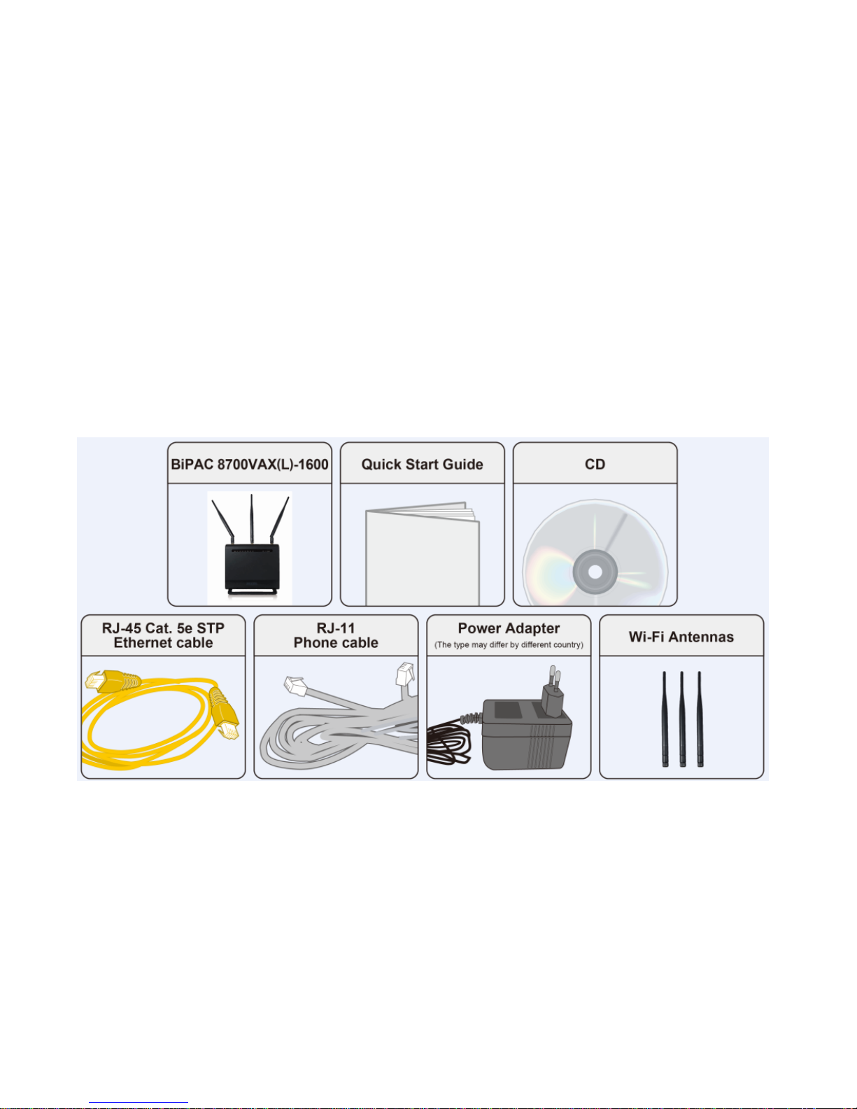
Package Contents
• BiPAC 8700VAX(L)-1600 Triple-WAN Wireless 1600Mbps 3G/4G LTE VoIP (VPN)
VDSL2/ADSL2+ Firewalls Router
• Vertical Stand
• Quick Start Guide
• CD containing the on-line manual
• Three detachable external Wi-Fi Antennas for 5G
• RJ-45 Cat. 5e STP Ethernet cable
• RJ-11 telephone cable
• Power adapter
• Splitter / Micro-filter (Optional)
Page 15

10
Important note for using this router
Warning
1. Do not use the router in high humidity or high temperatures.
2. Do not use the same power source for the router as other equipment.
3. Do not open or repair the case yourself. If the router is too hot, turn off the power
immediately and have it repaired at a qualified service center.
4. Avoid using this product and all accessories outdoors.
Attention
1. Place the router on a stable surface.
2. Only use the power adapter that comes with the package. Using a different voltage rating
power adapter may damage the router.
Page 16
11
Device Description
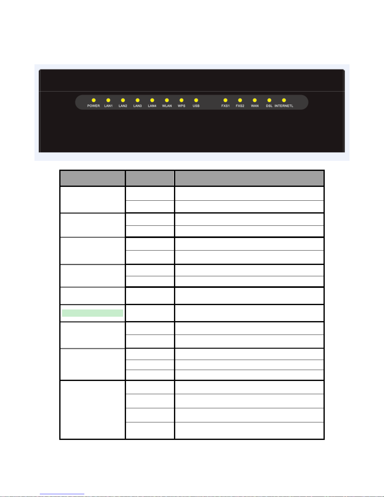
The Front LEDs
LED Status Meaning
Red Boot failure or in emergency mode
POWER
Green System ready
Green Successfully connected to a LAN device
LAN1~4
Off Data being transmitted / received
Green Wireless enabled (either 2.4G or 5G wireless).
WLAN(2.4G / 5G)
Blinking Data being transmitted / received.
Green Blinking WPS is enabled and trying to establish a WPS connection.
WPS
Off WPS process completed or WPS is off.
USB
Green
Successfully connected to a USB device (Printer, USB 2.0
storage, 4G/LTE USB modem)
FXS1/2
Green Phone off-hook.
Green
Successfully connected to an Ethernet device or to a
broadband device.
WAN
Blinking Data being transmitted / received
Green Successfully connected to an xDSL DSLAM (Line Synced)
Green Blinking xDSL synchronizing or waiting for DSL synchronizing
DSL
Off xDSL cable unplugged
Green IP connected and traffic is passing through the device
Blinking Data being transmitted / received
Red The router fails to obtain and IP.
Internet
Off
The router is either in bridged mode or WAN/DSL connection
is not ready
Page 17

12
The Rear Ports
5
3
47
9
8
10
6
Page 18

13
Port Meaning
1
POWER
Connect the supplied Power Adapter to this port.
2 ON/OFF Power ON/OFF switch
3
Gigabit
WAN
Connect to Fibre/ Cable/ xDSL Modem with a RJ-45 cable, for
broadband connectivity
* Note: this port is a LAN/WAN configurable port.
4 LAN1~4
Connect a STP Ethernet cable to one of the four LAN ports when
connecting to a PC or an office/home network of 10Mbps /100Mbps
/1000Mbps
5 USB
Connect the USB device (Printer, USB 2.0 storage, 3G/LTE 3G USB
modem) to this port.
6
FXS1/2、
(RJ-11
connector)
Connect your analog phone set to this port with the RJ-11 cable
7 DSL Connect to the xDSL/ telephone network with RJ-11 cable(telephone)
8 WPS
Press & hold the button for 2 seconds to trigger WPS function
* For WPS configuration, please refer to the WPS section in the
User Manual.
9 WLAN
Press & hold the button for more than 6 seconds to enable/disable
wireless
10 Reset
Push and hold the reset button for 5 seconds to restore to its factory
default settings (this is used when you cannot login to the router, e.g.
forgot your password).
Page 19

14
Cabling
One of the most common causes of problems is bad cabling or ADSL line(s). Make sure that all
connected devices are turned on. On the front panel of your router is a bank of LEDs. Verify that the
LAN Link and ADSL line LEDs are all lit. If they are not, verify if you are using the proper cables. If
the error persists, you may have a hardware problem. In this case, you should contact technical
support.
Make sure you have a line filter with all devices (e.g. telephones, fax machines, analogue modems)
connected to the same telephone line and the wall socket (unless you are using a Central Splitter or
Central Filter installed by a qualified and licensed electrician), and ensure that all line filters are
correctly installed and the right way around. Missing line filters or line filters installed the wrong way
around can cause problems with your ADSL connection, including causing frequent disconnections.
If you have a back-to-base alarm system you should contact your security provider for a technician
to make any necessary changes.
Page 20

15
Chapter 3: Basic Installation
The router can be configured through your web browser. A web browser is included as a standard
application in the following operating systems: Linux, Mac OS / Windows10 / Windows 8, Windows
7 / XP / Vista, etc. The product provides an easy and user-friendly interface for configuration.
Please check your PC network components. The TCP/IP protocol stack and Ethernet network
adapter must be installed. If not, please refer to your Windows-related or other operating system
manuals.
There are ways to connect the router, either through an external repeater hub or connect directly
to your PCs. However, make sure that your PCs have an Ethernet interface installed properly prior
to connecting the router device. You ought to configure your PCs to obtain an IP address through
a DHCP server or a fixed IP address that must be in the same subnet as the router. The default IP
address of the router is 192.168.1.254 and the subnet mask is 255.255.255.0 (i.e. any attached PC
must be in the same subnet, and have an IP address in the range of 192.168.1.1 to 192.168.1.253).
The best and easiest way is to configure the PC to get an IP address automatically from the router
using DHCP. If you encounter any problem accessing the router web interface it is advisable to
uninstall your firewall program on your PCs, as they can cause problems accessing the IP address
of the router. Users should make their own decisions on what is best to protect their network.
Please follow the following steps to configure your PC network environment.
Any TCP/IP capable workstation can be used to communicate with or through this router. To
configure other types of workstations, please consult your manufacturer documentation.
Page 21

16
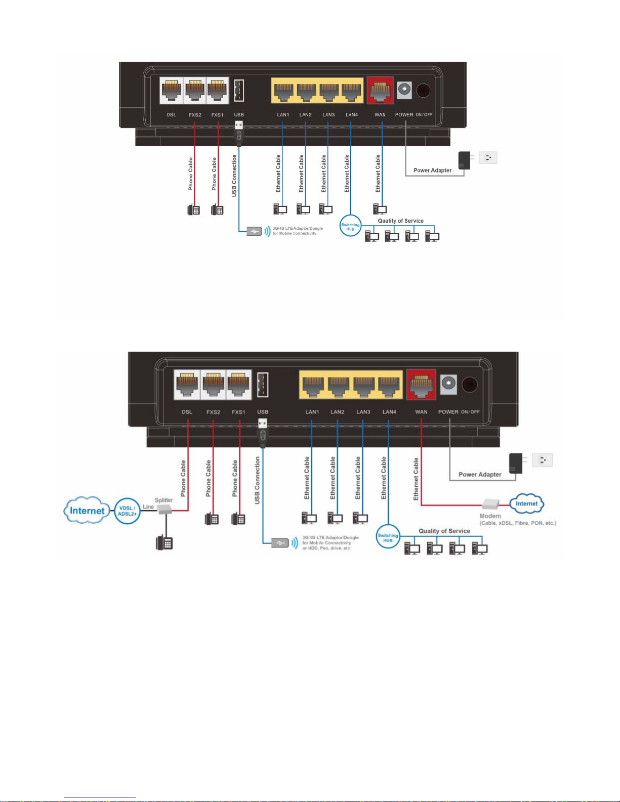
Connecting Your Router
Users can connect the VDSL2/ADSL2+ VoIP router as the following.
DSL mode
Broadband mode
Page 22
17
3G/4G LTE mode
Failover/fallback mode
Page 23

18
Network Configuration
Configuring a PC in Windows 7/ 8/ 10
1. For Windows 7/8, go to Start.
Click on Control Panel.
2. For Windows 10, Users can click
Start then click on Settings; or
right click the mouse when it
points at Windows ICON (Start),
then click Control Panel.
3. Click on Network and Internet.
4. When the Network and Sharing
Center window pops up, select
and click on Change adapter
settings on the left window
panel.
5. Select the Local Area
Connection, and right click the
icon to select Properties.
Settings of Windows 10
Control Panel
Page 24
19
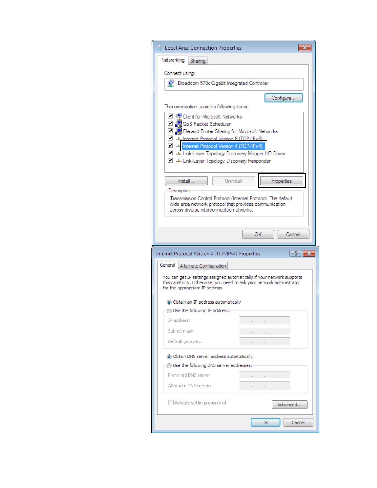
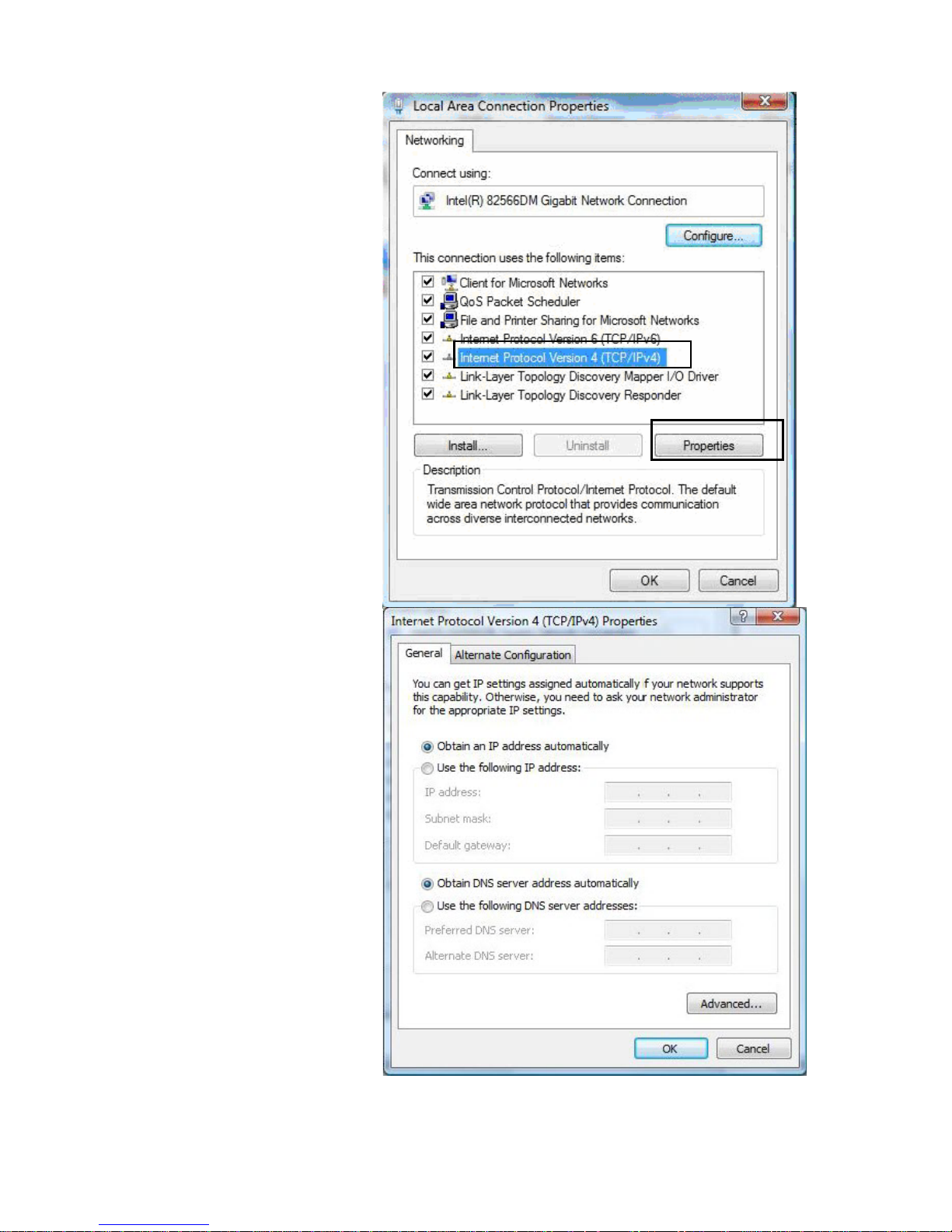
IPv4:
6. Select Internet Protocol
Version 4 (TCP/IPv4) then click
Properties
7. In the TCP/IPv4 properties
window, select the Obtain an IP
address automatically and
Obtain DNS Server address
automatically radio buttons.
Then click OK to exit the setting.
8. Click OK again in the Local
Area Connection Properties
window to apply the new
configuration.
Page 25
20
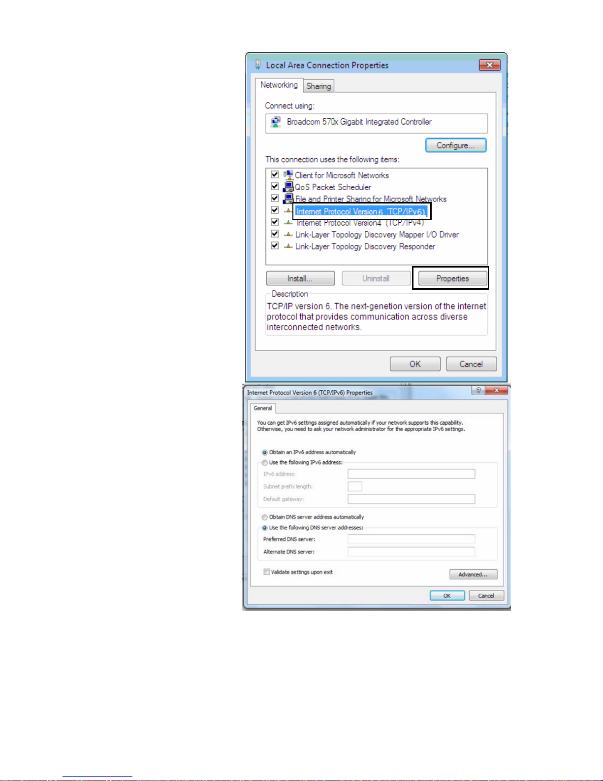
IPv6:
6. Select Internet Protocol
Version 6 (TCP/IPv6) then click
Properties
7. In the TCP/IPv6 properties
window, select the Obtain an
IPv6 address automatically and
Obtain DNS Server address
automatically radio buttons.
Then click OK to exit the setting.
8. Click OK again in the Local Area
Connection Properties window
to apply the new configuration.
Page 26

21
Configuring a PC in Windows Vista
1. Go to Start. Click on Network.
2. Then click on Network and
Sharing Center at the top bar.
3. When the Network and Sharing
Center window pops up, select
and click on Manage network
connections on the left window
pane.
4. Select the Local Area
Connection, and right click the
icon to select Properties.
Page 27
22
IPv4:
5. Select Internet Protocol
Version 4 (TCP/IPv4) then click
Properties.
6. In the TCP/IPv4 properties
window, select the Obtain an IP
address automatically and
Obtain DNS Server address
automatically radio buttons.
Then click OK to exit the setting.
7. Click OK again in the Local Area
Connection Properties window
to apply the new configuration.
Page 28
23
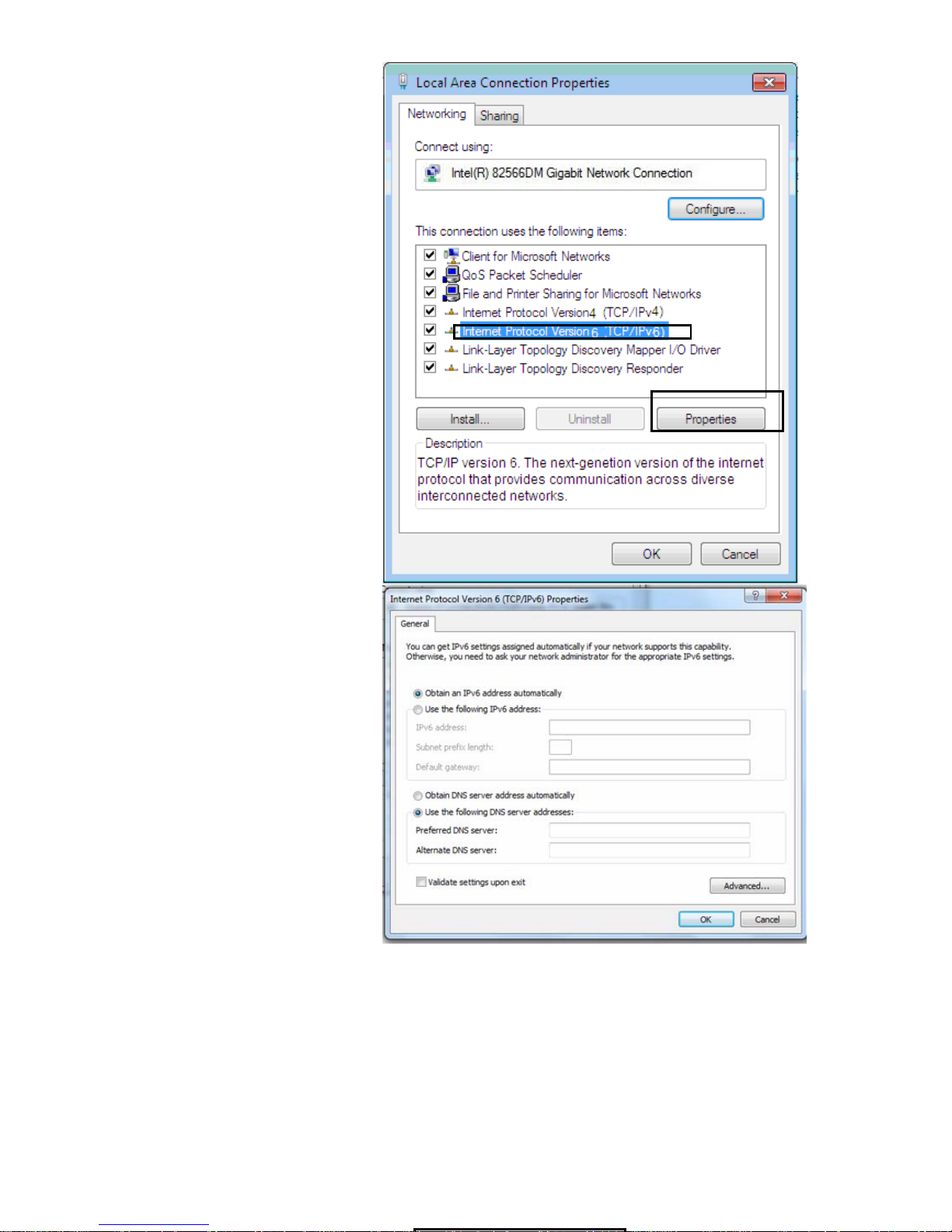
IPv6:
5. Select Internet Protocol
Version 6 (TCP/IPv6) then click
Properties.
6. In the TCP/IPv6 properties
window, select the Obtain an
IPv6 address automatically and
Obtain DNS Server address
automatically radio buttons.
Then click OK to exit the setting.
7. Click OK again in the Local Area
Connection Properties window
to apply the new configuration.
Page 29
24
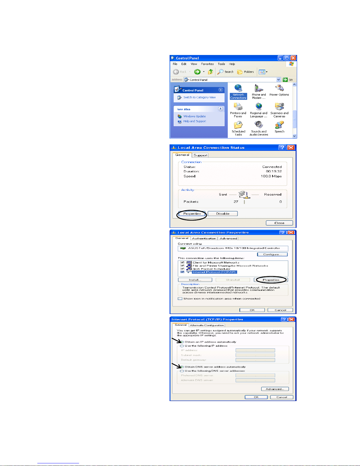
Configuring a PC in Windows XP
IPv4:
1. Go to Start / Control Panel (in Classic
View). In the Control Panel, double-click
on Network Connections
2. Double-click Local Area Connection.
3. In the Local Area Connection Status
window, click Properties.
4. Select Internet Protocol (TCP/IP) and
click Properties.
5. Select the Obtain an IP address
automatically and the Obtain DNS
server address automatically radio
buttons.
6. Click OK to finish the configuration.
Page 30
25
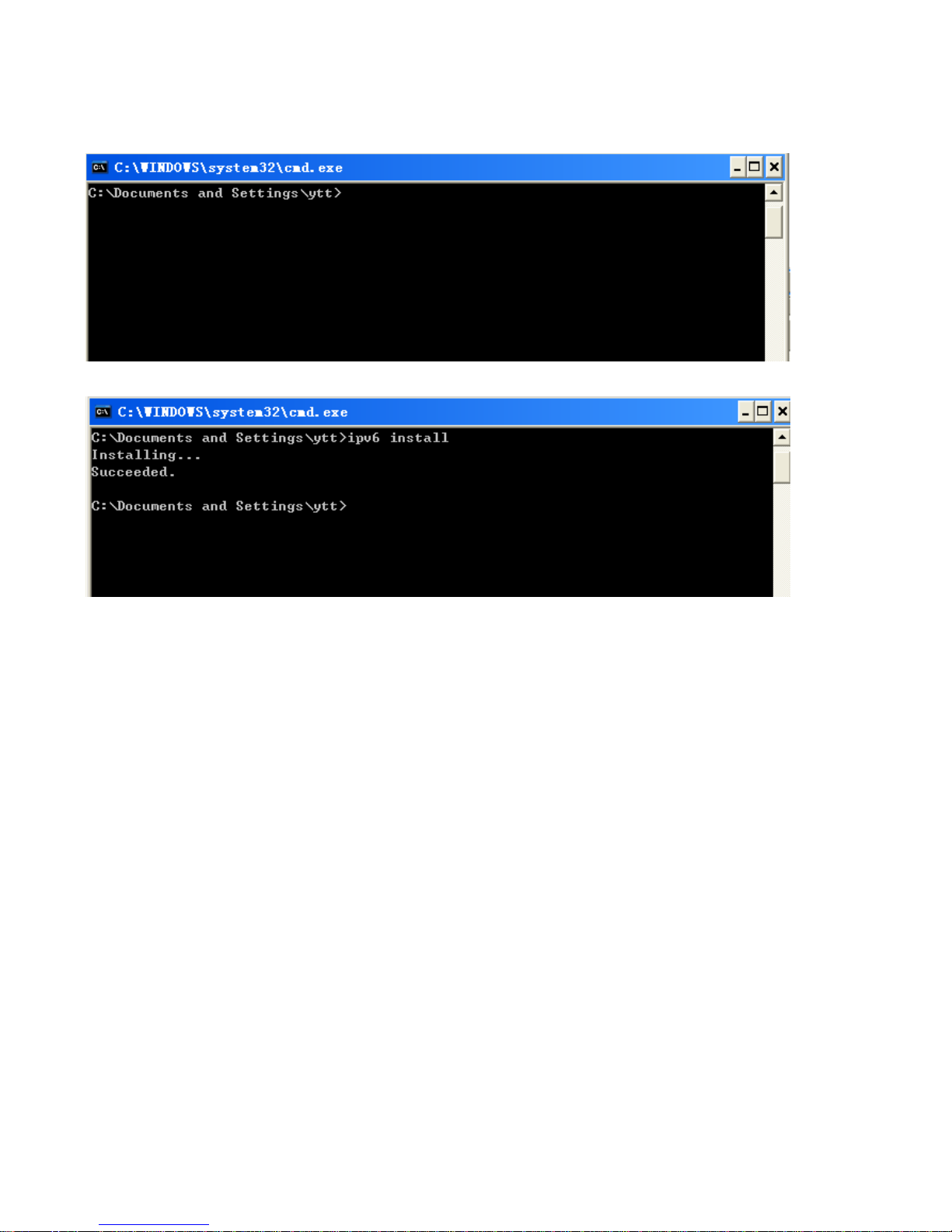
IPv6:
IPv6 is supported by Windows XP, but you should install it first.
Act as shown below:
1. On the desktop, Click Start > Run, type cmd, then press Enter key in the keyboard, the following screen
appears.
2. Key in command ipv6 install
Configuration is OK now, you can test whether it works ok.
Page 31

26
Factory Default Settings
Before configuring your router, you need to know the following default settings.
Web Interface (Username and Password)
Three user levels are provided by this router, namely Administrator, Remote and Local
respectively. See Access Control .
Administrator
Username: admin
Password: admin
Local
Username: user
Password: user
Remote
Username: support
Password: support
Attention
If you have forgotten the username and/or password of the router, you can restore the device
to its default setting by pressing the Reset Button more than 5 seconds.
Device LAN IPv4 settings
IPv4 Address: 192.168.1.254
Subnet Mask: 255.255.255.0
Device LAN IPv6 settings
IPv6 Address / prefix: Default is a link-local address and is different from each other as MAC
address is different from one to one. For example: fe80:0000:0000:0000:0204:edff:fe01:0001 / 64,
the prefix initiates by fe80::
DHCP server for IPv4
DHCP server is enabled.
Start IP Address: 192.168.1.254
IP pool counts: 100
Page 32

27
LAN and WAN Port Addresses
The parameters of LAN and WAN ports are pre-set in the factory. The default values are shown in
the table.
IPv4
LAN Port
WAN Port
IPv4 address 192.168.1.254
Subnet Mask 255.255.255.0
DHCP server function Enabled
IP addresses for
distribution to PCs
100 IP addresses continuing
from 192.168.1.100 through
192.168.1.199
The PPPoE function is
enabled to automatically get
the WAN port configuration
from the ISP.
IPv6
LAN Port
WAN Port
IPv6 address/prefix Default is a link-local address and is
different from each other as MAC
address is different from one to one.
For example :
fe80::204:edff:fe01:1/64,
the prefix initiates by fe80::
DHCP server function Enabled
The PPPoE function is
enabled to automatically get
the WAN port configuration
from the ISP.
Page 33

28
Information from your ISP
Before configuring this device, you have to check with your ISP (Internet Service Provider) to find
out what kind of service is provided.
Gather the information as illustrated in the following table and keep it for reference.
PPPoE(RFC2516)
VPI/VCI, VC / LLC-based multiplexing, Username, Password, Service
Name, and Domain Name System (DNS) IP address (it can be
automatically assigned by your ISP when you connect or be set manually).
PPPoA(RFC2364)
VPI/VCI, VC / LLC-based multiplexing, Username, Password and Domain
Name System (DNS) IP address (it can be automatically assigned by your
ISP when you connect or be set manually).
DHCP Client
VPI/VCI, VC / LLC-based multiplexing, Domain Name System (DNS) IP
address (it can be automatically assigned by your ISP when you connect or
be set manually).
IPoA(RFC1577)
VPI/VCI, VC / LLC-based multiplexing, IP address, Subnet mask, Gateway
address, and Domain Name System (DNS) IP address (it is a fixed IP
address).
Pure Bridge
VPI/VCI, VC / LLC-based multiplexing to use Bridged Mode.
Page 34

29
Easy Sign On (EZSO)
This special feature makes it easier for you to configure your router so that you can connect to the
internet in a matter of seconds without having to logon to the router GUI for any detail configuration.
This configuration method is usually auto initiated if user is to connect to the internet via Billion's
router for the first time.
After setting up the router with all the appropriate cables plugged-in, open up your IE browser, the
EZSO WEB GUI will automatically pop up and request that you enter some basic information that
you have obtained from your ISP. By following the instructions given carefully and through the
information you provide, the router will be configured in no time and you will find yourself surfing the
internet sooner than you realize.
EZSO window pops up:
Step1: Set the administration password.
Step 2: Set the Time Zone.
Step 3: Configure the WAN interface.
DSL mode (ADSL mode, please choose ATM; VDSL, please choose PTM)
Here take ADSL for example.
Before configuring with DSL mode, please confirm you have correctly connected the DSL line, and it
is now synchronized.
Select DSL, press Continue to go on to next step, press “Done” to quit the setting.
1. Enter the username, password from your ISP, for IP and DNS settings; also refer to your ISP.
Here IPv6 service is enabled by default.
Page 35

30
If the DSL line doesn’t synchronize, the page will pop up warning of the DSL connection failure.
3. Wait while the device is configured (DSL synchronized).
4. WAN port configuration is success and next to wireless, if you want skip wireless setting, click
Done.
Click Done, web configuration will be loaded, you will enter the web configuration page.
Page 36

31
5. After the configuration is successful, click Next to Wireless button and you may proceed to
configure the Wireless setting. The 8700VAX(L)-1600 supports dual-band wireless, here you can set
to activate wireless on which band or both and set the SSID and encryption Key. (1. Leave it empty
to disable the wireless security; 2. Fill in the Key, and the encryption mode will be WPA2-PSK/AES).
6. Continue to set 2.4GHz wireless.
7. Set the VoIP parameters. First user should turn to a VoIP service provider to register a SIP
account, write down the registration information and fill it in the following blanks. For detail, please
refer to VoIP.
Page 37

32
8. In the above page, click finish to complete the EZSO settings.
Page 38

33
Ethernet mode
1. Select Ethernet, press Continue to go on to next step.
2. Enter the username, password from your ISP, for IP and DNS settings, also refer to your ISP.
Here IPv6 service is enabled by default.
3. Wait while the device is configured.
4. WAN port configuration is success.
Click Done, web configuration will be loaded, you will enter the web configuration page.
Page 39

34
5. After the configuration is successful, click Next to Wireless button and you may proceed to
configure the Wireless setting. The 8700VAX(L)-1600 supports dual-band wireless, here you can set
to activate wireless on which band or both and set the SSID and encryption Key (1. Leave it empty to
disable the wireless security; 2. Fill in the Key, and the encryption mode will be WPA2-PSK/AES).
6. Continue to set 2.4GHz wireless.
7. Set the VoIP parameters. First user should turn to a VoIP service provider to register a SIP
account, write down the registration information and fill it in the following blanks. For detail, please
refer to VoIP.
Page 40

35
8. In the above page, click finish to complete the EZSO settings.
Page 41

36
3G/4G LTE
1. Select 3G/4G LTE, press Continue to go on to next step.
2. Enter the APN, username, password from your ISP, for settings about Authentication method, PIN,
etc, also refer to your ISP.
3. Wait while the device is configured.
4. WAN port configuration is success.
Click Done, web configuration will be loaded, you will enter the web configuration page.
Page 42

37
5. After the configuration is successful, click Next to Wireless button and you may proceed to
configure the Wireless setting. The 8700VAX(L)-1600 supports dual-band wireless, here you can set
to activate wireless on which band or both and set the SSID and encryption Key (1. Leave it empty to
disable the wireless security; 2. Fill in the Key, and the encryption mode will be WPA2-PSK/AES).
6. Continue to set 2.4GHz wireless.
7. Set the VoIP parameters. First user should turn to a VoIP service provider to register a SIP
account, write down the registration information and fill it in the following blanks. For detail,
please refer to VoIP.
Page 43

38
8. In the above page, click finish to complete the EZSO settings.
Page 44

39
Chapter 4: Configuration
Configuration via Web Interface
Open your web browser; enter the IP address of your router, which by default is 192.168.1.254, and
click or press ‘Enter’ key on the keyboard, a login prompt window will appear. The default root
username and password are “admin” and “admin” respectively.
Congratulations! You are now successfully logged in to the VDSL2/ADSL2+ Router!
Page 45

40
Once you have logged on to your BiPAC 8700VAX(L)-1600 Router via your web browser, you can
begin to set it up according to your requirements. On the configuration homepage, the left navigation
pane links you directly to the setup pages, which include:
Status (Summary, WAN, Statistics, Bandwidth Usage, 3G/4G LTE Status, Route, ARP, DHCP,
VPN, Log, VoIP)
Quick Start (Quick Start)
Configuration (LAN, Wireless 5G(wl0), Wireless 2.4G(wl1), WAN, System, USB, IP Tunnel,
Security, Quality of Service, NAT, Wake On LAN)
VPN (IPSec, VPN Account, Exceptional Rule Group, PPTP, L2TP, OpenVPN, GRE)
VoIP (SIP Devices, Service Provider, SIP Account, Call Block, VOIP Dial Plan, Phone Book)
Advanced Setup (Routing, DNS, Static ARP, UPnP, Certificate, Multicast, Management,
Diagnostics)
Page 46

41
Status
This Section gives users an easy access to the information about the working router and access to
view the current status of the router. Here Summary, WAN, Statistics, Bandwidth Usage, 3G/4G
LTE Status, Route, ARP, DHCP , VPN , Log and VOIP subsections are included.
Page 47

42
Summary
The basic information about the device is provided here (the following is a configured
screenshots to let users understand clearly).
Device Information
Model Name: Displays the model name.
Host Name: Displays the name of the router.
System Up-Time: Displays the elapsed time since the device is on.
Date/Time: Displays the current exact date and time. Sync button is to synchronize the
Date/Time with your PC time without regard to connecting to internet or not.
Software Version: Firmware version.
LAN IPv4 Address: Displays the LAN IPv4 address.
LAN IPv6 Address: Displays the LAN IPv6 address. Default is a Link-Local address, but
when connects to ISP, it will display the Global Address, like above figure.
MAC Address: Displays the MAC address.
DSL PHY and Driver Version: Display DSL PHY and Driver version.
Wireless Driver Version: Displays wireless driver version.
WAN
Line Rate – Upstream (Kbps): Displays Upstream line Rate in Kbps.
Line Rate – Downstream (Kbps): Displays Downstream line Rate in Kbps.
Default Gateway/IPv4 Address: Display Default Gateway and the IPv4 address.
Connection Time: Displays the elapsed time since ADSL connection is up.
Primary DNS Server: Displays IPV4 address of Primary DNS Server.
Secondary DNS Server: Displays IPV4 address of Secondary DNS Server.
Default IPv6 Gateway/IPv6 Address: Display the IPv6 Gateway and the obtained IPv6
address.
Page 48

43
WAN
This table displays the information of the WAN connections, users can turn here for WAN connection
information.
Interface: The WAN connection interface.
Description: The description of this connection.
Type: The protocol used by this connection.
Status: To disconnect or connect the link.
Connection Time: The WAN connection time since WAN is up.
IPv4 Address: The WAN IPv4 Address the device obtained.
IPv6 Address: The WAN IPv6 Address the device obtained.
DNS: The DNS address the device obtained.
Page 49

44
Statistics
LAN
The table shows the statistics of LAN.
Note: P5 is a configurable WAN/LAN port.
Interface: List each LAN interface. P1-P4 indicates the LAN interfaces (P5/WAN can work as a LAN
port).
Bytes: Display the total Received and Transmitted traffic statistics in Bytes for each interface.
Packets: Display the total Received and Transmitted traffic statistics in Packets for each interface.
Errors: Display the total statistics of errors arising in Receiving or Transmitting data for each
interface.
Drops: Display the total statistics of drops arising in Receiving or Transmitting data for each
interface.
Multicast (packets): Display the Received and Transmitted multicast Packets for each interface.
Unicast (packets): Display the Received and Transmitted unicast Packets for each interface.
Broadcast (packets): Display the Received and Transmitted broadcast Packets for each interface.
Reset: Press this button to refresh the statistics.
Page 50

45
WAN Service
The table shows the statistics of WAN.
Interface: Display the connection interface.
Description: The description for the connection.
Bytes: Display the Received and Transmitted traffic statistics in Bytes for every WAN interface.
Packets: Display the Received and Transmitted traffic statistics in Packests for every WAN interface.
Errors: Display the statistics of errors arising in Receiving or Transmitting data for every WAN
interface.
Drops: Display the statistics of drops arising in Receiving or Transmitting data for every WAN
interface.
Multicast (packets): Display the Received and Transmitted multicast Packets for every WAN
interface.
Unicast (packets): Display the Received and Transmitted unicast Packets for every WAN interface.
Broadcast (packets): Display the Received and Transmitted broadcast Packets for every WAN
interface.
Reset: Press this button to refresh the statistics.
xTM
The Statistics-xTM screen displays all the xTM statistics
Port Number: Shows number of the port for xTM.
In Octets: Number of received octets over the interface.
Out Octets: Number of transmitted octets over the interface.
In Packets: Number of received packets over the interface.
Out Packets: Number of transmitted packets over the interface.
In OAM Cells: Number of OAM cells received.
Out OAM Cells: Number of OAM cells transmitted.
Page 51

46
In ASM Cells: Number of ASM cells received.
Out ASM Cells: Number of ASM cells transmitted.
In Packet Errors: Number of received packets with errors.
In Cell Errors: Number of received cells with errors.
Reset: Click to reset the statistics.
xDSL
Mode: Modulation protocol, including G.dmt, G.lite, T1.413, ADSL2, AnnexL, ADSL2+ and AnnexM.
Traffic Type: Transfer mode, here supports ATM and PTM.
Status: Show the status of DSL link.
Link Power State: Show link output power state.
Page 52

47
Line Coding (Trellis): Trellis on/off.
SNR Margin (dB): Show the Signal to Noise Ratio(SNR) margin.
Attenuation (dB): This is estimate of average loop attenuation of signal.
Output Power (dBm): Show the output power.
Attainable Rate (Kbps): The sync rate you would obtain.
Rate (Kbps): Show the downstream and upstream rate in Kbps.
MSGc (#of bytes in overhead channel message): The number of bytes in overhead channel
message.
B (# of bytes in Mux Data Frame): The number of bytes in Mux Data frame.
M (# of Mux Data Frames in FEC Data Frame): The number of Mux Data frames in FEC frame.
T (Mux Data Frames over sync bytes): The number of Mux Data frames over all the sync bytes.
R (# of check bytes in FEC Data Frame): The number of check bytes in FEC frame.
S (ratio of FEC over PMD Data Frame length): The ratio of FEC over PMD Data frame length
L (# of bits in PMD Data Frame): The number of bit in PMD Data frame
D (interleaver depth): Show the interleaver depth.
Delay (msec): Show the delay time in msec.
INP (DMT symbol): Show the DMT symbol.
Super Frames: The total number of super frames.
Super Frame Errors: the total number of super frame errors.
RS Words: Total number of Reed-Solomon code errors.
RS Correctable Errors: Total number of RS with correctable errors.
RS Uncorrectable Errors: Total number of RS words with uncorrectable errors.
HEC Errors: Total number of Header Error Checksum errors.
OCD Errors: Total number of out-of-cell Delineation errors.
LCD Errors: Total number of Loss of Cell Delineation.
Total Cells: Total number of cells.
Data Cells: Total number of data cells.
Bit Errors: Total number of bit errors.
Total ES: Total Number of Errored Seconds.
Total SES: Total Number of Severely Errored Seconds.
Total UAS: Total Number of Unavailable Seconds.
xDSL BER Test: Click this button to start a bit Error Rate Test. The ADSL Bit Error Rate (BER) test
determines the quality of the ADSL connection. The test is done by transferring idle cells containing
a known pattern and comparing the received data with this known pattern to check for any errors.
Page 53

48
Select the Tested Time(sec), press Start to start test.
When it is OK, the following test result window will appear. You can view the quality of ADSL
connection. Here the connection is OK.
Reset: Click this button to reset the statistics.
Page 54

49
Bandwidth Usage
Bandwidth Usage provides users direct view of bandwidth usage with simple diagram. Bandwidth
usage shows the use of the bandwidth from two angles: Transmitted and Received, giving users a
clear idea of the usage.
LAN
Note: P5 is a configurable WAN/LAN port (here the example is in broadband WAN mode, p5
working as a WAN port).
Press View LAN Transmitted button to change the diagram to the statistics of the LAN Transmitted
Bytes. (Note: means Ethernet port #1, and the traffic information of the port #2 is identified with
blue, the same color with port#2 in the diagram; other ports all take the same mechanism.)
Page 55

50
When you press View WAN Traffic concurrently button, the WAN Bandwidth Usage pops up so
that users can view the WAN traffic concurrently.
Page 56

51
WAN Service
Press View WAN Transmitted button to change the diagram to the statistics of the WAN
Transmitted Bytes.
Page 57

52
Press View LAN Traffic concurrently button to directly switch to the LAN Bandwidth Usage page
to view the LAN traffic concurrently.
Page 58

53
3G/4G LTE Status
Status: The current status of the 3G/4G LTE connection.
Signal Strength: The signal strength bar and dBm value indicates the current 3G/4G-LTE signal
strength. The front panel 3G/4G LTE Signal Strength LED indicates the signal strength as well.
Network Name: The name of the 3G/4G LTE network the router is connecting to.
Network Mode: The current operation mode for 3G/4G LTE module, it depends on service provider
and card’s limitation, GSM or UMTS.
Card Name: Given a name for the embedded 3G/4G LTE module.
Card Firmware: Current used FW in the 3G/4G LTE module.
Current Received (RX) /Transmitted (TX) Bytes: Current Rx/TX (receive/transmit) packets in Byte
Total Received (RX) /Transmitted (TX) Bytes: The total Rx/TX (receive/transmit) packets in Byte
Total Connection Time: The total of 3G/4G LTE dongle connection time since the 3G/4G LTE is up
and running
Page 59

54
Route
Destination: The IP address of destination network.
Gateway: The IP address of the gateway this route uses.
Subnet Mask: The destination subnet mask.
Flag: Show the status of the route.
L U: Show the route is activated or enabled.
L H (host): destination is host not the subnet.
L G: Show that the outside gateway is needed to forward packets in this route.
L R: Show that the route is reinstated from dynamic routing.
L D: Show that the route is dynamically installed by daemon or redirecting.
L M: Show the route is modified from routing daemon or redirect.
Metric: Display the number of hops counted as the Metric of the route.
Service: Display the service that this route uses.
Interface: Display the existing interface this route uses.
Page 60

55
ARP
This section displays the router’s ARP (Address Resolution Protocol) Table, which shows the
mapping of Internet (IP) addresses to Ethernet (MAC) addresses. This is useful as a quick way of
determining the MAC address of the network interface of your PCs to use with the router’s Security
– MAC Filtering function. Here IPv6 Neighbor Table, listed with IPv6 address-MAC mapping, is
supported.
ARP table
IP Address: Shows the IP Address of the device that the MAC address maps to.
Flag: Shows the current status of the ARP entries.
L Complete: the route resolving is processing well.
L M(Marked as permanent entry): the route is permanent.
L P (publish entry): publish this route item.
MAC Address: Shows the MAC address that is corresponded to the IP address of the device it is
mapped to.
Device: here refers to the physical interface, it is a concept to identify Clients from LAN or WAN. For
example, the Clients in LAN, here displays “br0”.
Mark: Show clearly the SSID (WLAN) the device is in.
Neighbor Cache Table
IPv6 address: Shows the IPv6 Address of the device that the MAC address maps to.
MAC Address: Shows the MAC address that is corresponded to the IPv6 address of the device it is
mapped to.
Device: here refers to the physical interface, it is a concept to identify Clients from LAN or WAN. For
example, the Clients in LAN, here displays “br0”.
Mark: Show clearly the SSID (WLAN) the device is in.
Page 61

56
DHCP
The DHCP Table lists the DHCP lease information for all IP addresses assigned by the DHCP server
in the device.
Host Name: The Host Name of DHCP client.
MAC Address: The MAC Address of internal DHCP client host.
IP Address: The IP address which is assigned to the host with this MAC address.
Expires in: Show the remaining time after registration.
Mark: Show clearly the SSID (WLAN) the device is in.
Page 62

57
VPN
VPN status viewing section provides users IPSec, PPTP, L2TP, OpenVPN and GRE VPN status.
IPSec
Name: The IPSec connection name.
Active: Display the connection status.
Local Subnet: Display the local network.
Remote Subnet: Display the remote network.
Remote Gateway: The remote gateway address.
SA: The Security Association for this IPSec entry.
Refresh: Click this button to refresh the tunnel status.
Page 63

58
PPTP
PPTP Server
Name: The PPTP connection name.
Enable: Display the connection status with icon.
Status: The connection status.
Connection Type: Remote Access or LAN to LAN.
Peer Network IP: Display the remote (client side) network and subnet mask in LAN to LAN PPTP
connection.
Connected By: Display the IP of remotely connected client.
Action: Act to the connection. Click Drop button to disconnect the tunnel connection.
PPTP Client
Name: The PPTP connection name.
Enable: Display the connection status with icon.
Status: The connection status.
Connection Type: Remote Access or LAN to LAN.
Peer Network IP: Display the remote (server side) network and subnet mask.
Client: Assigned IP by PPTP server.
Action: Act to the connection. Click Disconnect button to disconnect the tunnel connection.
Refresh: Click this button to refresh the connection status.
Page 64

59
L2TP
L2TP Server
Name: The L2TP connection name.
Enable: Display the connection status with icon.
Status: The connection status.
Connection Type: Remote Access or LAN to LAN.
Peer Network IP: Display the remote (client side) network and subnet mask in LAN to LAN L2TP
connection.
Connected By: Display the IP of remotely connected client.
Action: Act to the connection. Click Drop button to disconnect the tunnel connection.
L2TP Client
Name: The L2TP connection name.
Enable: Display the connection status with icon.
Status: The connection status.
Connection Type: Remote Access or LAN to LAN.
Peer Network IP: Display the network and subnet mask of server side.
Client: Assigned IP by L2TP server.
Action: Act to the connection. Click Disconnect button to disconnect the tunnel connection.
Refresh: Click this button to refresh the connection status.
Page 65

60
OpenVPN
OpenVPN Server
Name: The OpenVPN connection name.
Enable: Display the connection status with icon.
Status: The connection status.
Connection Type: Remote Access or LAN to LAN.
Peer Network IP: Display the subnet address of client side in LAN to LAN mode.
Server IP: The tunnel virtual IP of server side assigned by server itself.
Connected By: The assigned tunnel virtual IP to remotely connected OpenVPN client.
Action: Act to the connection. Click Drop button to disconnect the tunnel connection.
OpenVPN Client
Name: The OpenVPN connection name.
Enable: Display the connection status with icon.
Status: The connection status.
Peer Network IP: Display the tunnel virtual address (WAN address) of server side.
Client IP: Assigned tunnel virtual IP by OpenVPN server.
Action: Act to the connection. Click Disconnect button to disconnect the tunnel connection.
Refresh: Click this button to refresh the connection status.
Page 66

61
GRE
Name: The GRE connection name.
Enable: Display the connection status with icons.
Status: The connection status, connected or disable.
Remote Gateway: The IP of remote gateway.
Refresh: Click this button to refresh the connection status.
Page 67

62
Log
System Log
Display system logs accumulated up to the present time. You can trace historical information with
this function. And the log policy can be configured in Configure Log section.
Refresh: Click to update the system log.
Clear: Click to clear the current log from the screen.
Page 68

63
Security Log
Security log displays the message logged about security, like filter messages and some firewall
message. You can turn to
IP Filtering Outgoing, IP Filtering Incoming, URL Filter to determine if you
want to log this information. Also you can turn to Configure Log section below to determine the level
to log the message. You can use this to track potential threats to your system and network.
Refresh: Click to update the security log.
Clear: Click to clear the current log from the screen.
Page 69

64
VoIP
Status
This VoIP status table displays the status of the VoIP phone usage, including Username - the
username registered in SIP Account, Host- the SIP registrar address, Status – the process in use,
Registered Time – the lasting period since the VoIP is up.
Page 70

65
Incoming Call Log
Incoming call log monitors incoming calls. It records all incoming call information ranging from Date,
Time, Duration, Caller ID, Caller Number & My Numb er.
Page 71

66
Outgoing Call Log
Outgoing call log monitors outgoing calls. It records all outgoing call information ranging from Date,
Time, Duration, Caller ID, Caller Number & My Numb er.
Page 72

67
Missed Call Log
Missed call log monitors missed calls. It records all missed call information ranging from Date, Time,
Duration, CallerID, Caller Number, My Number and Mark - the reason why the call is not
answered, with possible value reading DND, CF, CB or empty.
Page 73

68
Quick Start
Quick Start
This part allows you to quickly configure and connect your router to internet.
DSL mode (ADSL mode, please choose ATM; VDSL, please choose PTM)
Here take ADSL for example.
Select DSL, press Continue to go on to next step. Enter the username, password from your ISP, for
IP and DNS settings; also refer to your ISP. Here IPv6 service is enabled by default.
If the DSL line is not synchronized, the page will pop up warning of the DSL connection failure.
Page 74

69
3. Wait while the device is configured.
4. WAN port configuration is successful.
5. After the configuration is successful, click Next to Wireless button and you may proceed to
configure the Wireless setting. The 8700VAX(L)-1600 supports dual-band wireless, here you can set
to activate wireless on which band or both and set the SSID and encryption Key (1. Leave it empty
to disable the wireless security; 2. Fill in the Key, and the encryption mode will be WPA2-PSK/AES).
6. Continue to set 2.4GHz wireless.
Page 75

70
7. Set the VoIP parameters. First user should turn to a VoIP service provider to register a SIP
account, please write down the registration information and fill it in the following blanks.
In this page, user can continue to add SIP account and configure dial plan, for more, please refer to
SIP Account and VoIP Plan.
.
Page 76

71
Ethernet mode
1. Select Ethernet, press Continue to go on to next step.
2. Enter the username, password from your ISP, for IP and DNS settings; also refer to your ISP.
Here IPv6 service is enabled by default.
3. Wait while the device is configured.
4. WAN port configuration is successful.
Page 77

72
5. After the configuration is successful, click Next to Wireless button and you may proceed to
configure the Wireless setting. The device supports dual-band wireless connections, in Quick Start
part, users can only enable or disable the wireless on the band and the exact SSID and encryption
Key (1. Leave it empty to disable the wireless security; 2. Fill in the Key, and the encryption mode
will be WPA2-PSK/AES). For detail setting, please go to the Wireless part in this Manual.
6. Continue to set 2.4GHz wireless.
Page 78

73
7. Set the VoIP parameters. First user should turn to a VoIP service provider to register a SIP
account, please write down the registration information and fill it in the following blanks.
In this page, user can continue to add SIP account and configure dial plan, for more, please refer to
SIP Account and VoIP Plan.
Page 79

74
3G/4G LTE
1. Select 3G/4G LTE, press Continue to go on to next step.
2. Select the 3G mode, and enter the APN, username, password from your ISP; and check with your
ISP with the authentication method setting.
3. Wait while the device is configured.
4. WAN port configuration is successful.
Page 80

75
5. After the configuration is successful, click Next to Wireless button and you may proceed to
configure the Wireless setting. The device supports dual-band wireless connections, in Quick Start
part, users can only enable or disable the wireless on the band and the exact SSID and encryption
Key (1. Leave it empty to disable the wireless security; 2. Fill in the Key, and the encryption mode
will be WPA2-PSK/AES). For detail setting, please go to the Wireless part in this Manual.
6. Continue to set 2.4 GHz wireless.
Page 81

76
7. Set the VoIP parameters. First user should turn to a VoIP service provider to register a SIP
account, please write down the registration information and fill it in the following blanks.
In this page, user can continue to add SIP account and configure dial plan, for more, please refer to
SIP Account and VoIP Plan.
Page 82

77
VoIP Quick Setup
“VoIP Quick Setup” links to quick VoIP setting pages. In this part, users can conduct the necessary
settings (SIP account, VoIP Dial Plan, etc) of VoIP for use. For detail settings, please refer to VoIP.
Picture1
Click Add SIP Account to add new sip accounts (set the registration information).
Picture2
Click Apply to save the settings.
Page 83

78
For example:
In picture1, click Configure Dial Plan to extend to configure the dial plan. Please go to VOIP Plan to
get more.
Picture3
Page 84

79
Configuration
When you click this item, the column will expand to display the sub-items that will allow you to further
configure your router.
LAN, Wireless 5G (wl0), Wireless 2.4G (wl1), WAN, System, USB, IP Tunnel, Security, Quality
of Service, NAT and Wake On LAN.
The function of each configuration sub-item is described in the following sections.
Page 85

80
LAN - Local Area Network
A Local Area Network (LAN) is a shared communication system network where many computers
are connected. This type of network is area defined and is usually limited to a confined region within
a building.
Ethernet
Parameters
Group Name: This refers to the group you set in Interface Grouping section; you can set the
parameters for the specific group. Select the group via the drop-down box. For more information
please refer to Interface Grouping of this manual.
IP address: the IP address of the router. Default is 192.168.1.254.
Subnet Mask: the default Subnet mask on the router.
IGMP Snooping: Enable or disable the IGMP Snooping function. Without IGMP snooping,
multicast traffic is treated in the same manner as broadcast traffic - that is, it is forwarded to all
ports. With IGMP snooping, multicast traffic of a group is only forwarded to ports that have
members of that group.”
When enabled, you will see two modes:
L Standard Mode: In standard mode, multicast traffic will flood to all bridge ports when no
client subscribes to a multicast group.
L Blocking Mode: In blocking mode, the multicast data will be blocked when there are no
client subscribes to a multicast group, it won’t flood to the bridge ports.
Page 86

81
IGMP LAN to LAN Multicast: Check to determine whether to support LAN to LAN (Intra LAN)
Multicast. If user want to have a multicast data source on LAN side and he wants to get IGMP
snooping enabled, then this LAN-to-LAN multicast feature should be enabled.
LAN side firewall: Enable to drop all traffic from the specified LAN group interface. After activating it,
all incoming packets by default will be dropped, and the user on the specified LAN group interface
can't access CPE anymore. But, you can still access the internet service. If user wants to manage
the CPE, please turn to
IP Filtering Incoming to add the allowing rules. Note that all incoming
packets by default will be dropped if the LAN side firewall is enabled and user cannot manage this
CPE from the specified LAN group.
DHCP Server
You can disable or enable the DHCP (Dynamic Host Configuration Protocol) server or enable the
router’s DHCP relay functions. The DHCP protocol allows your router to dynamically assign IP
addresses to PCs on your network if they are configured to obtain IP addresses automatically.
L Disable
Disable the DHCP Server function.
L Enable
Enable the DHCP function, enter the information wanted. Here as default.
Start IP Address: The start IP address of the range the DHCP Server used to assign to the Clients.
End IP Address: The end IP address f the range the DHCP Server used to assign to the Clients.
Leased Time (hour): The leased time for each DHCP Client.
Option 66: Click Enable to activate DHCP option 66 for some special devices, like IPTV Set Box.
The devices can get firmware or some special service from the TFTP server. User needs to set the
IP or hostname of the TFTP server.
User Router’s setting as DNS server: Select whether to enable use router’s setting as DNS server,
if enabled, the PCs on the LAN side obtain the router’s setting as DNS server. If disabled, please
specify exactly the primary/secondary DNS server.
Primary/Secondary DNS server: Specify your primary/secondary DNS server for your LAN devices.
L DHCP Server Relay
Page 87

82
DHCP Server IP Address: Please enter the DHCP Server IP address.
Static IP List
The specified IP will be assigned to the corresponding MAC Address listed in the following table
when DHCP Server assigns IP Addresses to Clients.
Press Add to the Static IP List.
Enter the MAC Address, IP Address, and then click Apply to confirm your settings. But the IP
assigned should be outside the range of 192.168.1.100-192.168.1.199.
IP Alias
This function allows the creation of multiple virtual IP interfaces on this router. It helps to connect two
or more local networks to the ISP or remote node.
IP Alias: Check whether to enable this function.
IP Address: Specify an IP address on this virtual interface.
Subnet Mask: Specify a subnet mask on this virtual interface.
Click Apply to apply your settings.
Page 88

83
IPv6 Autoconfig
The IPv6 address composes of two parts, the prefix and the interface ID.
There are two ways to dynamically configure IPv6 address on hosts. One is “stateful” configuration,
for example using DHCPv6 (which resembles its counterpart DHCP in IPv4.) In the stateful autoconfiguration model, hosts obtain interface addresses and/or configuration information and
parameters from a DHCPv6 server. The Server maintains a database that keeps track of which
addresses have been assigned to which hosts.
The second way is “stateless” configuration. Stateless auto-configuration requires no manual
configuration of hosts, minimal (if any) configuration of routers, and no additional servers. The
stateless mechanism allows a host to generate its own addresses using a combination of locally
available information (MAC address) and information (prefix) advertised by routers. Routers
advertise prefixes that identify the subnet(s) associated with a link, while hosts generate an
"interface identifier" that uniquely identifies an interface on a subnet. An address is formed by
combining the two. When using stateless configuration, you needn’t configure anything on the client.
Group Name: Here group refers to the group you set in Interface Grouping section, you can set
the parameters for the specific group. Select the group by the drop-down box. For more
information please refer to Interface Grouping of this manual.
Static LAN IPv6 Address Configuration
Interface Address / Prefix Length: Enter the static LAN IPv6 address.
IPv6 LAN application
DHCPv6 Server: Check whether to enable DHCPv6 server.
Page 89

84
DHCPv6 Server Type: Select Stateless or Stateful. When DHCPv6 is enabled, this parameter is
available. Stateless: If selected, the PCs in LAN are configured through RA mode, thus, the PCs in
LAN are configured through RA mode, to obtain the prefix message and generate an address using
a combination of locally available information (MAC address) and information (prefix) advertised by
routers, but they can obtain such information like DNS from DHCPv6 Server. St ateful: if selected,
the PCs in LAN will be configured like in IPv4 mode, thus obtain addresses and DNS information
from DHCPv6 server.
Start interface ID: Enter the start interface ID. The IPv6 address composed of two parts, thus, the
prefix and the interface ID. Interface is like the Host ID compared to IPv4.
End interface ID: Enter the end interface ID.
Note: Interface ID does NOT support ZERO COMPRESSION "::". Please enter the complete
information.
For example: Please enter "0:0:0:2" instead of "::2".
Leased Time (hour): The leased time, similar to leased time in DHCPv4, is a time limit assigned to
clients, when expires, the assigned ID will be recycled and reassigned.
Issue Router Advertisement: Check whether to enable issue Router Advertisement feature. It is to
send Router Advertisement messages periodically.
ULA Prefix Advertisement: Enable this parameter to include the ipv6 ULA address in the RA
messages. ULA, unique local address, is an IPv6 address in the block fc00::/7. It is approximately
the IPv6 counterpart of the IPv4 private address. They are not routable in the global IPv6 Internet.
RADVD Type: The way that ULA prefix is generated.
L Randomly Generated
L Statically Configured: select to set manually in the following parameters.
Prefix: Set the prefix manually.
Preferred Life Time: The ULA prefix life time. When the time is over, the ULA prefix is invalid any
more, -1 means no limit.
Valid Life Time: It is a time threshold, when the time is over, clients should obtain new IPv6 address
from the router through RA; -1 means to be limitless.
MLD snooping: Similar to IGMP snooping, listens in on the MLD conversation between hosts and
routers by processing MLD packets sent in a multicast network, and it analyzes all MLD packets
between hosts and the connected multicast routers in the network. Without MLD snooping, multicast
traffic is treated in the same manner as broadcast traffic - that is, it is forwarded to all ports. With
MLD snooping, multicast traffic of a group is only forwarded to ports that have members of that
group.
L Standard Mode: In standard mode, multicast traffic will flood to all bridge ports when no
client subscribes to a multicast group.
L Blocking Mode: In blocking mode, the multicast data will be blocked when there is no
client subscribes to a multicast group, it won’t flood to the bridge ports.
MLD LAN to LAN Multicast: Check to determine whether to support LAN to LAN (Intra LAN)
Multicast. If user want to have a multicast data source on LAN side and he want to get MLD
snooping enabled, then this LAN-to-LAN multicast feature should be enabled
Page 90

85
Stateless and Stateful IPv6 address Configuration
Stateless: Two methods can be carried.
L With DHCPv6 disabled, but Issue Router Advertisement Enabled
With this method, the PCs in LAN are configured through RA mode, thus, the PCs in LAN are
configured through RA mode, to obtain the prefix message and generate an address using a
combination of locally available information (MAC address) and information (prefix) advertised by
routers.
L With both DHCPv6 and Issue Router Advertisement Enabled
With this method, the PCs’ addresses in LAN are configured like above method, but they can
obtain such information like DNS from DHCPv6 Server.
Page 91

86
Stateful: two methods can be adopted.
L With only DHCPv6 enabled
With this method, the PCs’ addresses are configured the same as in IPv4, that is addresses are
assigned by DHCPv6 server.
L With both DHCPv6 and Issue Router Advertisement Enabled
With this method, the PCs’ addresses are configured the same like above, and the address
information in RA packets will be neglected.
Page 92

87
Interface Grouping
Interface grouping is a function to group interfaces, known as VLAN. A Virtual LAN, commonly known
as a VLAN, is a group of hosts with the common set of requirements that communicate as if they were
attached to the same broadcast domain, regardless of the physical location. A VLAN has the same
attributes as a physical LAN, but it allows for end stations to be grouped together even if they are not
located on the same network switch.
Each group will perform as an independent network. To support this feature, you must create
mapping groups with appropriate LAN and WAN interfaces using the Add button.
(Please Note: P5 can be configured as EWAN, and when the device is in EWAN profile, there is no
P5/EWAN interface as P5 is working as a WAN port.)
Groups Isolation: If enabled, devices in one group are not able to access those in the other group.
Page 93

88
Click Add to add groups.
Group Name: Type a group name.
Grouped WAN Interfaces: Select from the box the WAN interface you want to applied in the group.
Grouped LAN Interfaces: Select the LAN interfaces you want to group as a single group from
Available LAN Interfaces.
Automatically Add Clients with following DHCP Vendor IDs: Enter the DHCP Vendor IDs for
which you want the Clients automatically added into the group. DHCP vendor ID (DHCP 60) is an
Authentication for DHCP Messages.
Click Apply to confirm your settings and your added group will be listed in the Interface Grouping
table below.
Page 94

89
In group "test", P2 and PPP0.1 are grouped in one group, they have their only network , see LAN.
If you want to remove the group, check the box as the following and press Remove.
Note: If you like to automatically add LAN clients to a WAN Interface in the new group add the
DHCP vendor ID string.
By configuring a DHCP vendor ID string any DHCP client request with the specified vendor
ID (DHCP option 60) will be denied an IP address from the local DHCP server.
If a vendor ID is configured for a specific client device, please REBOOT the client device
attached to the modem to allow it to obtain an appropriate IP address.
Each LAN interface can only be added into one group and one WAN interface can only be
used in one group.
Page 95

90
Wireless 5G(wl0) & 2.4G(Wl1)
BiPAC 8700VAX(L)-1600 is a simultaneous dual-band (2.4G and 5G) wireless router supporting
11b/g/n/a/ac wireless standards. It allows multiple wireless users on 2.4G and 5G radio bands to
surf the Internet, checking e-mail, watching video, listening to music over the Internet concurrently.
You can choose the optimum radio band wireless connection base on your environment.
Page 96

91
Basic
It let you determine whether to enable Wireless function and set the basic parameters of an AP and
the Virtual APs.
Wireless: Default setting is set to Enable. If you do not have any wireless devices, check the
checkbox again to unselect.
Hide SSID: It is function in which transmits its SSID to the air so that when wireless client searches
for a network, router can then be discovered and recognized. Check the checkbox to determine
whether you want to hide SSID.
Clients Isolation: if you enabled this function, then each of your wireless clients will not be able to
communicate with each other.
Disable WMM Advertise: Stop the router from ‘advertising’ its Wireless Multimedia (WMM)
functionality, which provides basic quality of service for time-sensitive applications (e.g. VoIP, Video).
Check to disable or enable this function.
Wireless multicast Forwarding (WMF): check to enable or disable wireless multicast forwarding.
SSID: The SSID is the unique name of a wireless access point (AP) to be distinguished from another.
For security purpose, change the default wlan-ap-2.4g to a unique ID name to the AP already built-
in to the router’s wireless interface. It is case sensitive and must not excess 32 characters. Make
sure your wireless clients have exactly the SSID as the device, in order to get connected to your
network.
Note: SSID is case sensitive and must not exceed 32 characters.
BSSID: Basic Set Service Identifier, it is a local managed IEEE MAC address, and is 48 bits value.
Country: Different countries have different wireless band resources, so you can select the
appropriate Country according to your location.
Max Clients: enter the number of max clients the wireless network can supports,1-16.
Guest/virtual Access Points: A “Virtual Access Point” is a logical entity that exists within a physical
Access Point (AP). When a single physical AP supports multiple “Virtual APs”, each Virtual AP
appears to stations (STAs) to be an independent physical AP, even though only a single physical AP
is present. For example, multiple Virtual APs might exist within a single physical AP, each advertising
Page 97

92
a distinct SSID and capability set. Alternatively, multiple Virtual APs might advertise the same SSID
but a different capability set – allowing access to be provided via Web Portal, WEP, and WPA
simultaneously. Where APs are shared by multiple providers, Virtual APs provide each provider with
separate authentication and accounting data for their users, as well as diagnostic information,
without sharing sensitive management traffic or data between providers. You can enable the virtual
AP.
Here you can enable some Virtual APs according to the request. And the other parameters of virtual
APs are the same to the above.
Click Apply to apply your settings.
Page 98

93
Security
Wireless security prevents unauthorized access or damage to computers using wireless network.
Note:
The WPS feature will also be unavailable when the security setting is not WPA2 PSK or OPEN. So,
if you manually set the wireless security setting, you should give notice to it, but you can find prompt
indicating configuration.
Manual Setup AP
Select SSID: select the SSID you want these settings apply to.
Network Authentication
L Open
WEP Encryption: Select to enable or disable WEP Encryption. Here select Enable.
Encryption Strength: Select the strength, 128-bit or 64-bit.
Current Network Key: Select the one to be the current network key. Please refer to key 1- 4 below.
Network Key (1- 4): Enter 13 ASCII characters or 26 hexadecimal digits for 128-bit encryption keys.
Enter 5 ASCII characters or 10 hexadecimal digits for 64-bit encryption keys.
Page 99

94
L Shared
This is similar to network authentication ‘Open’. But here the WEP Encryption must be enabled.
L 802.1x
RADIUS Server IP Address: RADIUS( Remote Authentication Dial In User Service), Enter the
IP address of RADIUS authentication server.
RADIUS Server Port: Enter the port number of RADIUS authentication server here.
RADIUS Key: Enter the password of RADIUS authentication server.
WEP Encryption: Select to enable or disable WEP Encryption. Here select Enable.
Current Network Key: Select the one to be the current network key. Please refer to key 2- 3 below.
Network Key (1- 4): Enter 13 ASCII characters or 26 hexadecimal digits for 128-bit encryption keys.
Enter 5 ASCII characters or 10 hexadecimal digits for 64-bit encryption keys.
Page 100

95
L WPA2
Protected Management Frame: Select whether to enable protected management frame
mechanism. By default, it is disabled. If enabled, the network adapter of the attempting wireless
client should also support this feature.
WPA2 Preauthentication: When a wireless client wants to handoff to another AP, with
preauthentication, it can perform 802.1X authentication to the new AP, and when handoff happens,
this mode will help reduce the association time.
Network Re-auth Interval: the interval for network Re-authentication. This is in seconds.
WPA Group ReKey Internal: The period of renewal time for changing the security key automatically
between wireless client and Access Point (AP). This is in seconds.
RADIUS Server IP Address: RADIUS( Remote Authentication Dial In User Service), Enter the
IP address of RADIUS authentication server. This is in seconds.
RADIUS Server Port: Enter the port number of RADIUS authentication server here.
RADIUS Key: Enter the password of RADIUS authentication server.
WPA/WAPI Encryption: There are two Algorithms, AES (Advanced Encryption Standard) and
TKIP(Temporal Key Integrity Protocol) which help to protect the wireless communication.
L WPA2-PSK
Protected Management Frame: Select whether to enable protected management frame
mechanism. By default, it is disabled. If enabled, the network adapter of the attempting wireless
client should also support this feature.
WPA/WAPI passphrase: Enter the WPA.WAPI passphrase; you can click here to display to view it.
WPA Group ReKey Internal: The period of renewal time for changing the security key automatically
between wireless client and Access Point (AP). This is in seconds.
WPA/WAPI Encryption: There are two Algorithms, AES (Advanced Encryption Standard) and
TKIP(Temporal Key Integrity Protocol) which help to protect the wireless communication.
 Loading...