

Page 1
INSTALLATION MANUAL
CHEVROLET BIG BLOCK
V4120 / V4220
Billet Specialties, Inc.
500 Shawmut Avenue
La Grange, Illinois 60526
TECH Line 708.588.0505
Fax 708.588.7181
www.billetspecialties.com
Page 2
PLEASE READ ALL INSTRUCTIONS BEFORE INSTALLING ANY
COMPONENTS OF THE V-TRAC PULLEY SYSTEM
Tech Line: 708.588.0505
Fax: 708.588.7181
www.billetspecialties.com
Required Tools & Materials
Anti-seize Compound
RTV Silicone
Gasket Scraper
Scotch-Brite® Pad
3/8-16 Thread Chaser* & Holder
7/16-14 Thread Chaser*
*Thread chasers are available at your
local parts store and are different from
a thread cutting tap.
11/16” Combo Wrench
3/4” Combo Wrench
Socket Wrench & Extension
10mm 12pt. socket
12mm 12pt. socket
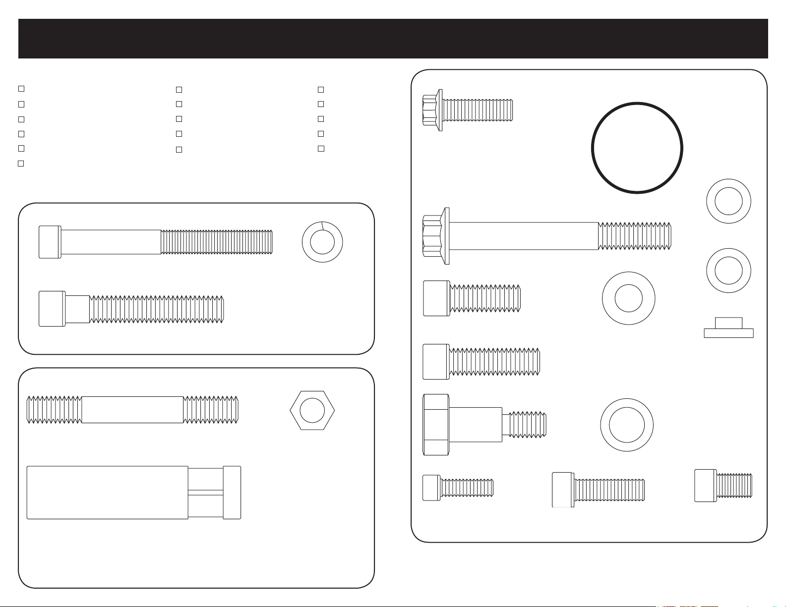
Skin Board #1 - Packaged with Power Steering Pump
5/16-24 x 3” Socket Head Cap Screw
(Power Steering Pump)
x2
7/16-14 x 2-1/4” Socket Head Cap Screw
(Power Steering Bracket)
x2
3/16” Allen
5/16” Allen
1/4” Allen
3/8” Allen
6mm Allen
x2
5/16”
Lock Washer
Skin Board #3 - Packaged In Main Box
x7
8mm-1.25 x 25mm
12pt. Cap Screw
(Bridge Bracket)
10mm-1.5 x 80mm 12pt. Cap Screw
(Alternator)
x3
3/8-16 x 1” Socket Head Cap Screw
(Crankshaft Pulley)
x2
3/8” Belleville Washer
(Crankshaft Pulley)
x4
O-Ring Set
x3
x1
8mm Slide Spacer
x2
10mm x .5mm
Shim Washer
x2
10mm x 1mm
Shim Washer
x2
Skin Board #2 - Packaged with Water Pump
3/8-16 x 3” Block Mounting Stud
Spacer Nut - 3”
7/16-14 x 1-1/2” Socket Head Cap Screw
(Alternator Bracket - Not used with Power Steering Kits)
x4
x4
x2
3/8-16 Zinc Coated
Hex Nuts
(Discard After Use)
x1
Compressor Shoulder Bolt
(A/C Compressor)
x3
1/4-20 x 3/4”
Socket Head Cap Screw
(Compressor Cover)
Other Hardware
Goodyear Gatorback V-Belt - Compressor 44-1/2”
Goodyear Gatorback V-Belt - Alternator 43” (w/o Power Steering) - 45” (w/ power steering)
8mm-1.25 x 25mm
Socket Head Cap Screw
(A/C Manifold)
x1
Compressor Shoulder
Bolt Washer
x2
5/16-24x1/2”
Socket Head Cap Screw
(Water Pump Pulley)
x4
Page 3
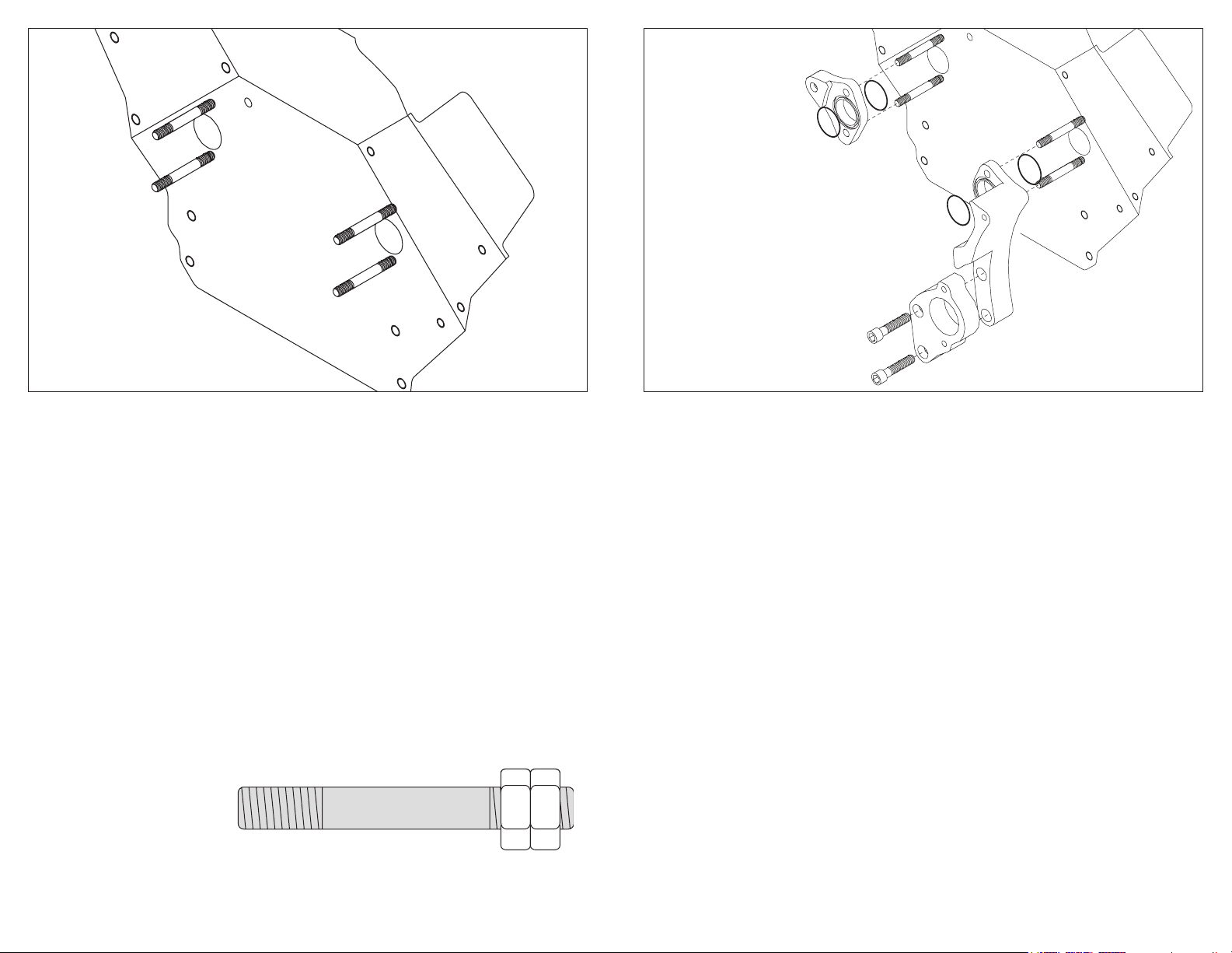
Figure 1: Prepping The Block
Disconnect battery & remove all existing accessory drive brackets and
components from motor.
Remove water pump, scrape away any existing gasket material with a gasket
scraper and dress surface with a Scotch Brite® pad.
Clean and prep threads on engine block at water pump (3/8-16) and driver side
bosses (7/16-14) by crank (for power steering kits). Use a 3/8-16 & 7/16-14 thread
chaser if necessary. Thread chasers are available at your local auto parts store or
tool dealer and are different from a thread cutting tool.
Apply RTV sealer to one end of the four 3/8-16 x 3” threaded studs and thread
studs into the water pump mounting holes and tighten.
The studs can easily be tightened by threading two 3/8-16 zinc coated nuts onto
the stud and tighten them against each other to act as a drive nut.
*Example
Figure 2: Install Alternator & A/C Brackets
Install the large O-rings into both sides of the passenger side compressor bracket
by seating them into the recessed groves. Place bracket over studs and seat up
against engine block.
Install the large O-rings into both sides of the driver side alternator bracket by
seating them into the recessed groves. Place bracket over studs and seat up
against engine block.
For kits with power steering – apply anti-seize to the threads of the two
7/16-14 x 2-1/4” socket head cap screws and thread through the power steering
bracket, alternator bracket and into engine block and finger tighten.
For kits without power steering – apply anti-seize to the threads of the two
7/16-14 x 1-1/2” socket head cap screws and thread through the alternator
bracket and into engine block and finger tighten.
TECH LINE: 708-588-0505 FAX 708-588-7181 www.billetspecialties.com
5
Page 4

Figure 3: Install Water Pump
Install water pump onto studs (make sure O-rings are still seated).
Figure 4: Install Power Steering Pump & Bridge Bracket
If you do not have power steering proceed to Step 2.
Apply anti-seize to exposed stud threads. Thread the four 3” spacer nuts onto the
studs with the hex end out. Tighten all spacer nuts firmly at this time.
Also tighten lower 7/16” cap screws on alternator bracket or power steering
bracket.
TECH LINE: 708-588-0505 FAX 708-588-7181 www.billetspecialties.com
STEP 1: Apply anti-seize to the threads of the two 5/16-24 x 3” socket head cap
screws. Place power steering pump and pulley onto bracket and thread the two
5/16” socket head cap screws with 5/16” lock washers through pump into
bracket and tighten firmly.
STEP 2: Apply anti-seize to the threads of four 8mm-1.25 x 25mm 12pt. ARP cap
screws. Align bridge bracket mount holes with the four spacer nuts. Install the four
8mm 12pt. ARP cap screws and tighten firmly.
7
Page 5

Compressor Side
*Flange of spacer fits into
adjustment slot on bracket.
Alternator Side
Figure 5: Install Alternator & A/C Compressor
Alternator: Apply anti-seize to the threads of the 10mm-1.5 x 8mm ARP 12pt. cap
screw and a 8mm-1.25 x 25mm ARP 12pt. cap screw. Place alternator between
lower bridge bracket and alternator bracket and thread the long ARP 12pt. cap
screw through the bridge bracket, alternator and into the alternator bracket and
finger tighten. 10mm shim washers are provided to shim the alternator boss to the
bridge bracket. The alternator boss may vary in width due to the polishing process. Place the 8mm slide spacer with the small end towards bridge bracket on
the short ARP 12pt. cap screw, align top alternator boss with bridge bracket and
thread the cap screw and slide spacer through bridge bracket and into alternator boss and finger tighten.
Compressor: Apply anti-seize to the threads of the 3/8-16 compressor shoulder
bolt and two 8mm-1.25 x 25mm ARP 12pt. cap screws. While supporting the
compressor, place the shoulder bolt and washer into the back compressor mount
boss and align with compressor bracket on motor and finger tighten. Thread one
8mm ARP 12pt. cap screw through bridge bracket and into lower compressor
boss and finger tighten. Place the 8mm slide spacer with the small end towards
bridge bracket on the short ARP 12pt. cap screw, align top compressor boss
with bridge bracket and thread the cap screw and slide spacer through bridge
bracket and into compressor boss and finger tighten.
TECH LINE: 708-588-0505 FAX 708-588-7181 www.billetspecialties.com
Figure 6: Install Crank Pulley, Water Pump Pulley, &
Compressor Clutch Cover
Install the crank pulley by applying anti-seize to the threads of the three
3/8-16 x 1” socket head cap screws, install the three 3/8” Belleville washers onto
each cap screw and thread through crank pulley into damper.
Install the water pump pulley by applying anti-seize to the threads of the four
5/16-24 x 1/2” socket head cap screws and threading them through the water
pump pulley into flange.
Install AC Compressor Clutch Cover
Apply Loctite Blue 242 to the following:
(3) 1/4-20 x 3/4” socket head cap screws
Place cover on clutch and thread the socket head cap screws through the cover
and into the clutch, torque to 40-45 inch/lbs.
Caution: Over tightening these festeners will cause damage to the compressor
clutch. Do Not Over Tighten.
Tighten all fasteners firmly.
9
Page 6

Without Power Steering
With Power Steering
Figure 7: Install A/C Compressor Manifold
Compressor Manifold – Read the precautions below, BEFORE installing the
compressor manifold. To install themanifold remove the bolts & protective cover,
being sure to leave the o-rings on compressor. Apply anti-seize to the threads of
the two 8mm-1.25 x 25mm socket head cap screws. Place manifold on
compressor and attach with the two 8mm cap screws and tighten firmly. Attach
compressor lines at this point or seal off threaded ends of manifold.
IMPORTANT
• Only remove sealed cap on compressor and install manifold if you plan on
charging your system immediately, leaving the compressor open to outside air
can introduce moisture into the system causing the cooling system not to
operate properly.
• Never connect the compressor clutch wire and run the compressor unless the
system is charged. Serious damage may occur to compressor. Do not install the
manifold unless you are going to finish installing the a/c hoses and never connect
the compressor clutch wire until system is ready to charge with Freon.
• Although the compressor is supplied with oil, the level may not be correct for
the entire system. Consult the instruction manual of the air conditioning unit for
proper levels and system charging procedures.
• Billet Specialties recommends having your air conditioning charged and
serviced by an automotive air conditioning service center with the proper
equipment to ensure many years of proper operation.
Figure 8: Install Belt
Route belts as shown in appropriate diagram, adjust alternator belt tension first.
Tighten alternator mounting hardware firmly. Adjust compressor belt tension,
tighten rear compressor shoulder bolt firmly then front compressor cap screw
firmly. Finish by tightening the top compressor cap screw.
Re-check all fasteners for tightness and proper belt tension. Connect all electrical
and start motor and allow to warm up. Turn motor off and re-check fasteners and
belts. Re-check after 100 miles.
Alternator Belt Length:
With Power Steering - 45”
Without Power Steering - 43”
Compressor Belt Length: 44-1/2”
TECH LINE: 708-588-0505 FAX 708-588-7181 www.billetspecialties.com
11
Page 7

V4120 / V4220
Billet Specialties, Inc.
500 Shawmut Avenue
La Grange, Illinois 60526
Tech Line 708-588-0505
Fax 708-588-7181
www.billetspecialties.com
 Loading...