

Page 1

Small Block Ford
289 / 302 / 351W / 5.0
Installation Manual
For Systems without A/C
#13605 / #13625
Billet Specialties, Inc.
500 Shawmut Avenue.
La Grange, Illinois 60526
Tech Line (708) 588-0505
Fax (708) 588-7181
Page 2
PLEASE READ ALL INSTRUCTIONS BEFORE INSTALLING ANY
COMPONENTS OF THE TRU TRAC SERPENTINE SYSTEM
Tech Line: 708.588.0505
Fax: 708.588.7181
www.billetspecialties.com
This kit is designed to be used with the following or similar 4 hole crankshaft
damper (not included)
289/302/351w 1970-1980 302, 1970-1997 351w
Professional Products #80045
Summit Racing #163289
Pioneer #DA-3513
Dimensions: 3.950” overall length 6.400” Dia.
5.0 1981-1995 5.0L
Ford Racing #M-6316-M50
Professional Products #80007
Summit Racing #163302
Pioneer #DA-3021
Dimensions: 3.950” overall length 6.400” Dia.
Other aftermarket dampers must be 3.950” overall length or less (space to 3.950”)
and cannot exceed 6.400” in diameter to clear water pump mount boss and
bolt. Damper must be 4-bolt pattern for crank pulley.
THIS KIT DOES NOT HAVE A PROVISION FOR MECHANICAL FUEL PUMP
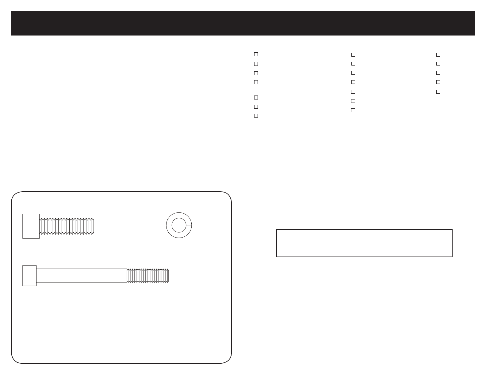
Skin Board #1 - Packaged with Power Steering Pump
Required Tools & Materials
Anti-seize Compound
RTV Silicone
New Oil Pan Gasket
Damper Puller
(Lisle P/N 45500 or similar)
Gasket Scraper
Scotch-Brite® Pad
5/16-18 Thread Chaser* & Holder
*Thread chasers are available at your
local parts store and are different from
a thread cutting tap.
1/2” Box End Wrench
5/8” Box End Wrench
3/4” Box End Wrench
11/16” Box End Wrench
Socket Wrench & Extension
10mm 12pt. socket
1/2” Socket
3/16” Allen
5/16” Allen
1/4” Allen
5/32” Allen
5mm Allen
x2
3/8-16 x 1-1/4” - Socket Head Cap Screw
(Power Steering Bracket)
5/16-24 x 3” - Socket Head Cap Screw
(Power Steering Pump)
x2
5/16”
Medium Split Lock Washer
(Power Steering Pump)
x2
TECH TIP:
Billet Specialties recommends the use of Anti-Seize on all
fasteners to prevent thread lock-up.
Page 3
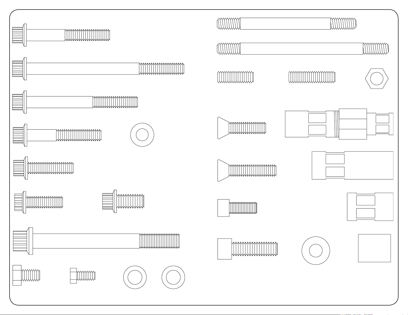
Skin Board #2 - Packaged In Main Box
x3
5/16-18 x 2-1/4” - 12pt. Cap Screw
(Water Pump & Timing Marker)
5/16-18 x 4-1/4” - 12pt. Cap Screw
(Water Pump)
5/16-18 x 3” - 12pt. Cap Screw
(Water Pump)
5/16-18 x 2” - 12pt. Cap Screw
(Timing Cover & Timing Marker)
x2
5/16-18 x 1-1/4” - 12pt. Cap Screw
(Water Pump)
x3
x2 x5
5/16” Flat Washer
(Water Pump)
x1
x1
5/16-18 x 3-3/4” - Block Mounting Stud
5/16-18 x 4-5/8” - Block Mounting Stud
x1
5/16-18 x 1” Socket Set Screw
(To Tensioner Spacer)
3/8-16 x 1-1/4” Threaded Stud
x1
8mm-1.25 x 25mm
Tensioner Coupler Nut Assembly x1
Flat Socket Cap Screw
(Bridge Bracket)
x2
8mm-1.25 x 30mm - Flat Socket Cap Screw
(To Tensioner)
x1
x2
5/16-18
Zinc Coated
Hex Nut
Spacer Nut - 2.197”
x1
x3
8mm-1.25 x 25mm
12pt. Cap Screw (Bridge Bracket)
10mm-1.5 x 100mm - 12pt. Cap Screw
(Alternator)
x2
1/4-20 x 1/2”
Hex Head Cap Screw
(Oil Pan)
x4
x2
5/16-18 x 1/2”
Hex Head Cap Screw
(Oil Pan)
x1
3/8-16 x 3/4” - 12pt. Cap Screw
(Tensioner Pulley)
x1
x2
10mm x .5mm
Shim Washer
(Alternator)
x2
10mm x 1mm
Shim Washer
(Alternator)
x4
5/16-24 x 3/4”
Socket Head Cap Screw
(Water Pump Pulley)
3/8-16 x 1-1/4”
Socket Head Cap Screw
(Crankshaft Pulley)
x4
x4
3/8” Belleville Washer
(Crankshaft Pulley)
Spacer Nut - 1.25”
Alternator Spacer
.875”
Other Hardware / Gaskets
Oil Pan Corner Gaskets & Oil Pan End Seal
Goodyear Poly-V Serpentine Belt - 57.75” #4060575 (with power steering)
Goodyear Poly-V Serpentine Belt - 55.5” #4060555 (without power steering)
x1
x1
Page 4
www.billetspecialties.com • Tech Line 708.588.0505
6
Small Block Ford Tru Trac - 13605 / 13625
7
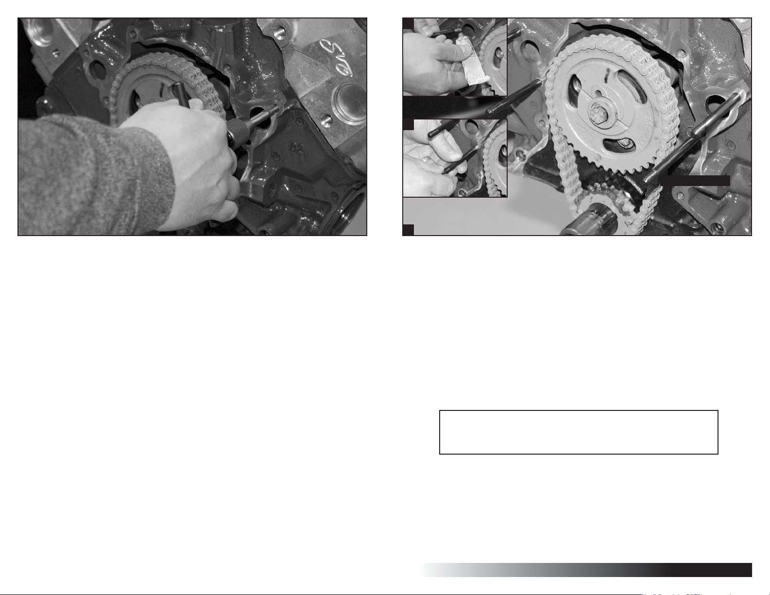
Figure 1: Engine Block Preparation
- Disconnect battery
- Remove existing alternator, air conditioning compressor and
associated brackets
- Remove all pulleys and water pump
- Use damper puller to remove damper
- Remove Timing cover
- Remove oil pan hardware and drop oil pan
If you are unable to remove the oil pan: First Cut the exposed oil pan
gasket flush with engine block using a sharp blade, then remove the first
three bolts from the oil pan on each side and loosen the remaining bolts
enough to allow the front of the oil pan to drop 3/8” to 1/2”.
- Remove all traces of gasket and sealer with gasket scraper and
Scotch-Brite® pad
- Clean crank snout with Scotch-Brite® pad
- Clean threads in block by chasing with a 5/16-18 thread chaser
A
B
5/16-18 x 4-5/8"
C
Figure 2: Install Mounting Studs
A,B] Apply RTV Silicone to two 5/16-18 x 3-3/4” threaded studs and thread studs
into passenger side of motor near water outlet and finger tighten.
C] Apply RTV Silicone to one 5/16-18 x 3-3/4” threaded stud and thread into
driver side top hole and finger tighten.
C] Take remaining 5/16-18 x 4-5/8” threaded stud, apply RTV Silicone and thread
into bottom hole.
TECH TIP:
Billet Specialties recommends the use of Anti-Seize on all
fasteners to prevent thread lock-up.
Important:
Remove fuel pump eccentric from cam gear; replace bolt & washer. Torque to
recomended spec.
Page 5

www.billetspecialties.com • Tech Line 708.588.0505
8
Small Block Ford Tru Trac - 13605 / 13625
9
Figure 3: Install Mounting Studs (Continued)
Figure 4: Prepare Timing Cover For Installation
Thread the two 5/16-18 zinc coated hex nuts onto one of the studs and tighten
against each other to act as a drive nut (see illustration below*); then seat the
stud firmly into the block. Repeat this for the three remaining studs.
Remove zinc coated hex nuts and discard.
Apply anti seize to exposed stud threads at this time.
*Example
Install oil pan end seal with a thin film of RTV silicone. If you were unable to
remove the oil pan install new corner gaskets at this time too.
Page 6

www.billetspecialties.com • Tech Line 708.588.0505
10
Small Block Ford Tru Trac - 13605 / 13625
11
B
B
C
A
Figure 5: Install Timing Cover & Gasket
Apply a thin film of RTV to back of timing cover and engine block surface.
A] Align and install timing cover gasket to block. Place timing cover over studs
and crank snout.
B] Thread one 5/16-18 x 2-1/4” ARP 12pt. bolt into driver side bottom hole on
timing cover and finger tighten.
D
Figure 6: Install Factory Timing Marker
A,B] Take factory steel timing marker and install one 5/16-18 x 2-1/4” ARP 12pt.
bolt through bottom hole of timing marker and thread into timing cover.
Thread one 5/16-18 x 2” ARP 12pt. bolt into other hole and finger tighten both
bolts.
C] Thread one 5/16-18 x 2” ARP 12pt. bolt into remaining driver side bottom hole
in timing cover and finger tighten.
If you did not remove the oil pan?
D] Install two 5/16-18 x 1/2" hex head cap screw through the holes nearest the
crankshaft and into the timing cover. Thread the two remaining 1/4-20 x 1/2" hex
head cap screws trough the corner holes of the oil pan into the timing cover.
Make sure corner gaskets line up with holes. Corner gaskets may need to be
trimmed to allow gaskets to sit flush with engine and
timing cover.
A
Page 7

www.billetspecialties.com • Tech Line 708.588.0505
12
Small Block Ford Tru Trac - 13605 / 13625
13
A
B
C
Figure 7: Install Water Pump
Apply a thin film of RTV silicone to water pump gasket and back of water pump.
Place water pump gasket on to timing cover and align. Install water pump over
studs and onto timing cover.
Figure 8: Install Spacer Nuts
A] Thread the two 2.197” spacer nuts with the hex end out onto the passenger
side water pump studs and finger tighten.
B] Thread the 1.569” spacer nut hex side out to the top driver side water pump
stud and finger tighten.
C] Thread the remaining short spacer nut on to the bottom water pump stud hex
side out (shown above) and finger tighten.
Page 8

www.billetspecialties.com • Tech Line 708.588.0505
14
Small Block Ford Tru Trac - 13605 / 13625
15
A
B
C
Figure 9: Complete Water Pump Installation
A] There are now five open holes remaining in the water pump, starting at the
top hole thread the 5/16-18 x 1-1/4” ARP 12pt. bolt and 5/16” flat washer into
hole and finger tighten.
B] Working in a clockwise direction, thread a 5/16-18 x 3” ARP 12pt. bolt and
5/16” flat washer into the next hole and finger tighten.
C] Continuing in a clockwise direction thread a 5/16-18 x 2-1/4” ARP 12pt. bolt
and 5/16” flat washer into the bottom right hole in the water pump and finger
tighten.
D] Thread a 5/16-18 x 1-1/4” ARP 12pt. bolt and 5/16” flat washer into the bottom
left hole in the water pump and finger tighten.
E] Moving on to the remaining hole in the water pump at the top, thread a
5/16-18 x 4-1/4” ARP 12pt. bolt and 5/16” flat washer into the hole and
finger tighten.
D
E
Figure 10: Oil Pan Installation (If Removed)
Install oil pan and gasket at this time, thread two 5/16-18 x 1/2" hex head cap
screw through the holes nearest the crankshaft and into the timing cover.
Thread the two remaining 1/4-20 x 1/2" hex head cap screws through the
corner holes of the oil pan into the timing cover.
Tighten all bolts at this time.
Note: Some aftermarket oil pans may require different length hardware.
Figure 10: Oil Pan Installation (If NOT Removed)
Tighten oil pan to motor and timing cover firmly
Tighten all bolts on the timing cover and then water pump at this time.
Page 9

www.billetspecialties.com • Tech Line 708.588.0505
16
Small Block Ford Tru Trac - 13605 / 13625
17
A
B
Figure 11: Install Power Steering Bracket & Pump
Figure 12: Install Crank Damper
At this time install the 4-bolt damper
and tigthen firmly.
A
If your kit does not include power steering proceed to Figure 12.
A] Place power steering bracket onto timing cover. Thread the two
3/8-16 x 1-1/4” socket head cap screws into bracket and tighten.
B] Attach power steering pump to bracket with two 5/16-24 x 3” socket head
cap screws and 5/16” split washers and tighten firmly.
B
Figure 13: Install Coupler Spacer & Stud
A] Apply anti-seize to the 3/8-16 x 1-1/4” threaded stud and thread into the top
passenger side ear of the timing cover & tighten.
B] Apply anti-seize to the exposed threads. Disassemble the tensioner coupler
assembly and thread the long spacer nut onto stud and tighten.
Page 10

www.billetspecialties.com • Tech Line 708.588.0505
18
Small Block Ford Tru Trac - 13605 / 13625
19
A
B
C
D
A
B
C D E
Figure 15: Install Tensioner
Figure 14: Install Bridge Bracket
Place the bridge bracket on the motor & align.
A,B] Apply anti-seize to the two 8mm-1.25 x 25mm ARP bolts and thread through
the bridge bracket into the driver side spacer nuts and finger tighten.
C] Apply anti-seize to the remaining 8mm-1.25 x 25mm ARP bolt and thread
through the bottom passenger side hole on the bridge bracket and into the
bottom spacer nut. Finger tighten.
D] Apply anti-seize to the 8mm-1.25 x 25mm flat socket cap screw and thread
through the bridge bracket into the remaining spacer nut on the passenger side
and finger tighten.
A] Apply anti-seize to the 5/16-18 x 1” socket set screw and thread into the back
of the tensioner. Apply anti-seize to the remaining threads on stud.
B] Thread the tensioner coupler spacer nut onto the tensioner and tighten.
C] Slide coupler nut back against the tensioner body.
D,E] Apply anti-seize to the two 8mm-1.25 x 30mm flat socket cap screws. Thread
through the bridge bracket into the tensioner and tighten.
Page 11

www.billetspecialties.com • Tech Line 708.588.0505
20
Small Block Ford Tru Trac - 13605 / 13625
21
A
A
B
Figure 16: Install Alternator
Apply anti-seize to the 10mm-1.5 x 100mm ARP 12pt. bolt. Place alternator
between bridge bracket and timing cover, aligning the bottom alternator
mounting hole with bridge bracket and timing cover.
A] Thread the 10mm-1.5 x 100mm ARP 12pt. bolt through the bridge bracket and
halfway through the alternator. Slide the alternator spacer into position between
the alternator and timing cover. Push bolt through the rest of the way and finger
tighten.
B] Apply anti-seize to the 8mm-1.25 x 25mm ARP 12pt. bolt. Align top alternator
mounting hole with bridge bracket, thread in the 8mm-1.25 x 25mm ARP 12pt.
bolt and tighten firmly.
B
Figure 17: Complete Bridge Bracket Installation
A] At this time tighten all bridge bracket bolts firmly, leave the bottom alternator
bolt loose and check to see if a shim needs to be added at this time.
The alternator mounting boss may vary in thickness due to the polishing process.
10mm shim washers are provided to shim alternator to bridge bracket (washers
may or may not be needed).
B] Thread the coupler nut onto the coupler spacer and tighten firmly.
Page 12

www.billetspecialties.com • Tech Line 708.588.0505
22
Small Block Ford Tru Trac - 13605 / 13625
23
Figure 18: Install Crankshaft Pulley
Install crank pulley with four 3/8-16 x 1” socket head cap screws and four 3/8”
Belleville washers and tighten firmly.
Note:
In some application it may be necesary to use a crankshaft pulley spacer for
proper belt alingment. Crankshaft pulley spacers are available at any Ford Racing
performance parts dealer.
A B
C
Spacer
Thickness (in.)
.350 M-8510-A351
.950 M-8510-B351
.875 M-8510-C351
.909 M-8510-D351
Figure 19: Install Water Pump Pulley
Install water pump pulley with four
5/16-24 x 3/4” socket head cap
screws and tighten firmly.
Check All Bolts For Tightness At This Time
Part Number
Figure 20: Install Tensioner Pulley & Serpentine Belt
A] Route serpentine belt as shown below. Wrap belt around tensioner pulley and
hold pulley in place.
B] Place a 5/8" socket with extension onto the tensioner nut. Rotate socket
handle clockwise until tensioner pulley slips onto tensioner shaft.
C] Release tension and install 3/8-16 x 3/4” ARP 12pt. bolt and washer onto
tensioner. Tighten firmly.
Belt Path Without Power Steering Belt Path With Power Steering
Page 13

#13605 / #13625
9/06
Billet Specialties, Inc.
500 Shawmut Avenue
La Grange, Illinois 60526
Tech Line 708.588.0505
Fax 708.588.7181
www.billetspecialties.com
 Loading...