

Page 1

HEMI / BB Chrysler
Installation Manual
For Systems without A/C
#14805 / #14825
Billet Specialties, Inc.
500 Shawmut Avenue.
La Grange, Illinois 60526
Tech Line (708) 588-0505
Fax (708) 588-7181
Page 2
PLEASE READ ALL INSTRUCTIONS BEFORE INSTALLING ANY
COMPONENTS OF THE TRU TRAC SERPENTINE SYSTEM
Tech Line: 708.588.0505
Fax: 708.588.7181
www.billetspecialties.com
IMPORTANT: Must use thin crank vibration damper Mopar Performance number
P3830183 or similar with this kit.
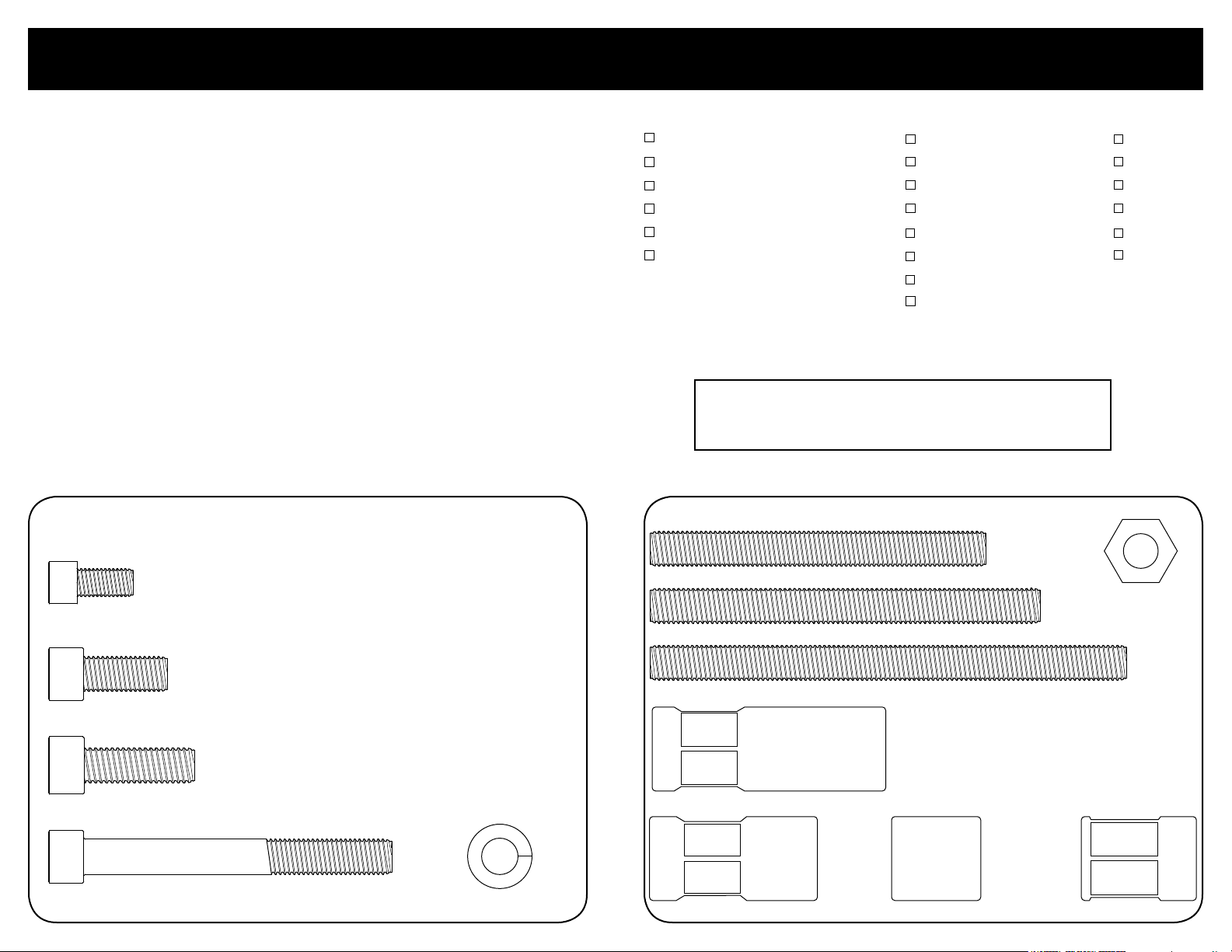
Skin Board #1 - Packaged with Power Steering Pump
x2
1/4-28 X 1/2” Socket Head Cap Screw
Power Steering Support Bracket To Bridge Bracket
Required Tools & Materials
Anti-seize Compound
RTV Silicone
Permatex Hylomar® gasket dressing
Gasket Scraper
Scotch-Brite® Pad
3/8-16 Thread Chaser* & Holder
*Thread chasers are available at your
local parts store and are different from
a thread cutting tap.
TECH TIP:
Billet Specialties recommends the use of Anti-Seize on all
fasteners to prevent thread lock-up.
5/8” Box End Wrench
9/16” Box End Wrench
3/4” Box End Wrench
11/16” Box End Wrench
Socket Wrench & Extension
10mm 12pt. socket
12mm 12pt. socket
3/8” 12pt. Socket
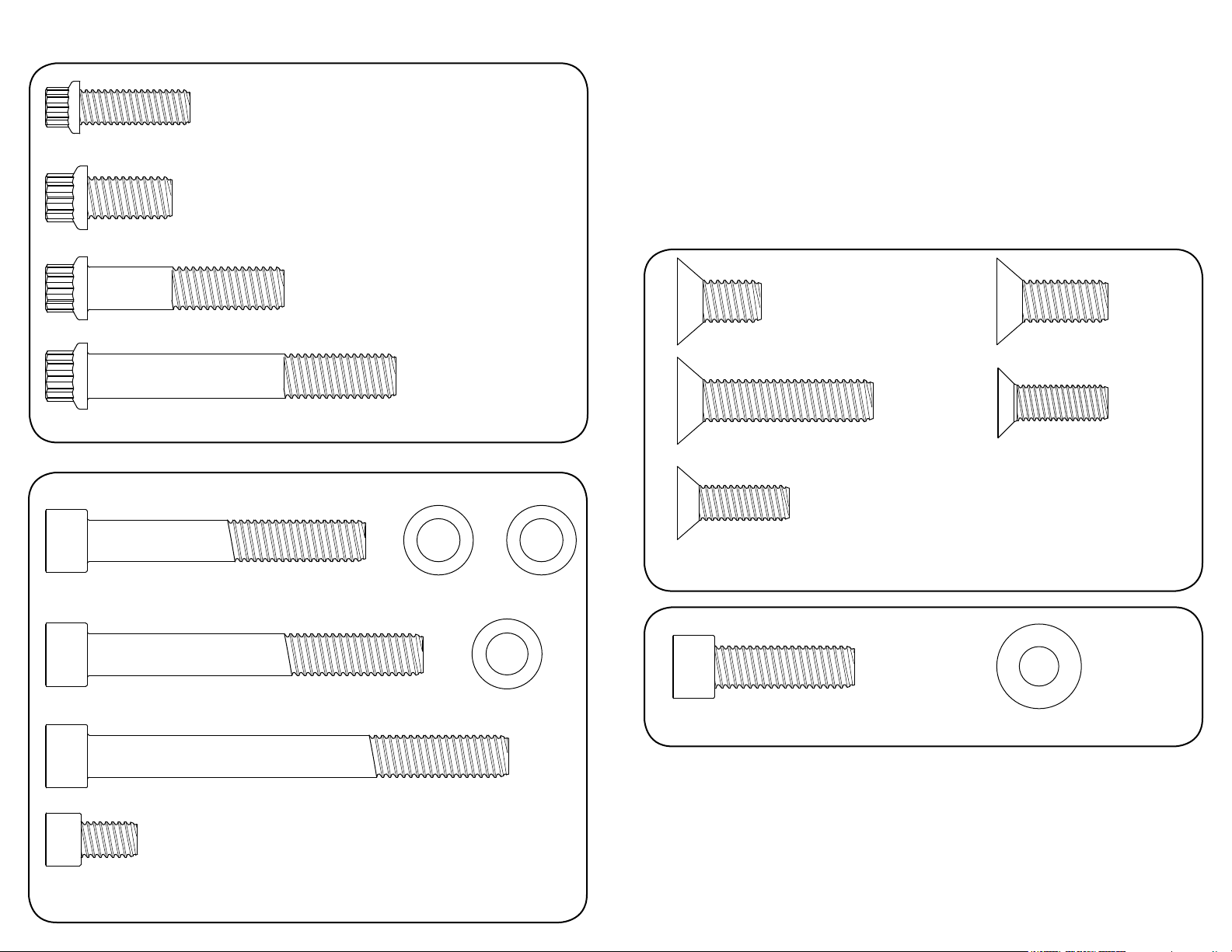
Skin Board #2 - Packaged with Water Pump
3/8-16 x 3” Block Mounting Stud
3/8-16 x 3-1/2” Block Mounting Stud
3/16” Allen
5/16” Allen
1/4” Allen
7/32” Allen
5mm Allen
6mm Allen
x1
x1
x2
3/8-16 Zinc Coated
Hex Nuts
x3
5/16-18 x 3/4” Socket Head Cap Screw
Power Steering Bracket To Alternator Bracket
x1
8mm-1.25 x 25mm Socket Head Cap Screw
Power Steering Pump To Power Steering Support Bracket
5/16-18 x 2-3/4” Socket Head Cap Screw
Power Steering Pump To Bracket
x1
3/8-16 x 4-1/4” Block Mounting Stud
x1
2-3/32” Spacer Nut
x2
x2
5/16” Lock Washer
x1x1x1
13/16” Spacer 1-1/32” Spacer Nut1-1/2” Spacer Nut
Page 3
Skin Board #3 - Packaged In Main Box
x1
8mm-1.25 x 25mm 12pt. Cap Screw
Bridge Bracket To Alternator
x1
3/8-16 x 3/4” 12pt. Cap Screw
Tensioner Pulley
3/8-16 x 1-3/4” 12pt. Cap Screw
Idler Pulleys
10mm-1.5 x 70mm 12pt. Cap Screw
Bridge Bracket To Alternator
3/8-16 x 2-1/2” Socket Head Cap Screw
Water Pump Housing To Block
3/8-16 x 3” Socket Head Cap Screw
Compressor Bracket To Block
x4
3/8-16 x 3/4” Flat Head Cap Screw
Thru Bridge Bracket Into Spacer Nut
x1
3/8-16 x 1-3/4” Flat Head Cap Screw
Thru Bridge Bracket To Water Pump Housing
x1
x2
10mm x .5mm
Shim Washer
x1
x2
10mm x 1mm
Shim Washer
x3
3/8” Flat Washer
x1
5/16-18 x 1” Flat Head Cap Screw
Bridge Bracket To Spacer Nut &
Tensioner To Bridge Bracket
5/16-18 x 1” Socket Head Cap Screw
Crankshaft & Water Pump Pulley
x1
3/8-16 x 1” Flat Head Cap Screw
Tensioner To Bridge Bracket
x1
8mm-1.25 x 25mm Flat Head Cap Screw
Bridge Bracket To Tensioner
x1
x10
5/16” Belleville Washer
Crank Pulley
x6
x1
x2
3/8-16 x 3-3/4” Socket Head Cap Screw
Water Pump Housing To Block
x1
5/16-18 x 1/2" Socket Head Cap Screw
Backside Of Tensioner Thru Bracket
Other Hardware / Gaskets
Goodyear Poly-V Serpentine Belt - 74.50” #4060745 (with power steering)
Goodyear Poly-V Serpentine Belt - 64.25” #4060642 (without power steering)
Page 4

www.billetspecialties.com
www.billetspecialties.com
7
[A]
1/2"
Figure 1 – Prepping The Block
Disconnect battery; remove all existing accessory drive brackets and components
from motor.
Remove water pump and housing, scrape away any existing gasket material with
a gasket scraper and dress surface with a Scotch Brite® pad.
Clean and prep threads on engine block at water pump, use a 3/8-16 thread
chaser if necessary. Thread chasers are available at your local auto parts store or
tool dealer and are different from a thread cutting tool.
Apply RTV sealer to one end of the 3/8-16 x 3” threaded stud and thread stud
into the driver side top water pump mount hole. Next apply RTV sealer to one
end of the 3/8-16 x 4-1/4” stud and thread into the lower driver side mount hole
and tighten. Apply RTV sealer to one end of the remaining 3/8-16 x 3-1/2” stud
and thread into the bottom passenger side mount hole and tighten. The studs
can easily be tightened by threading two 3/8-16 zinc coated nuts onto the stud
and tighten them against each other to act as a drive nut, see example. Apply
anti-seize to the exposed threads of the studs at this time. Check installed height
of studs by sliding water pump housing on to the studs. There should be 1/2” of
exposed threads on each stud, readjust as necessary.
[B]
[C]
Figure 2 – Install Water Pump Housing & Pump
Apply Permatex Hylomar® gasket dressing to both sides of water pump housing
gaskets and slip over studs on block. Install water pump housing onto studs make
sure top passenger gasket is still aligned.
(A) Apply anti-seize to the 3/8-16 x 2-1/2” socket head cap screw with 3/8”
washer and thread through water pump housing and into block, finger tighten.
(B) Thread the 2-3/32” long spacer nut to the driver side top stud and finger
tighten.
(C) Apply gasket dressing to both sides of water pump gasket and install water
pump to housing and tighten firmly. Seep hole on pump should point down.
Example
Page 5

www.billetspecialties.com
www.billetspecialties.com
9
[B]
[A]
[B]
[A]
Figure 3 - Install Tensioner Bracket
Place tensioner bracket (14827) on passenger side of water pump housing and
align with the two left mount bosses.
[A] Thread the 1-1/2" long spacer nut onto the lower stud and tighten firmly.
[B] Apply anti seize to the 3/8-16 x 3" socket head cap screw with 3/8" washer and
thread through tensioner bracket, water pump housing and into block,
tighten firmly.
Step 1
Figure 4 - Install Alternator Bracket
For kits without power steering proceed to Step 2.
Step 1: Attach the power steering pump bracket to the back of the alternator
bracket (14801) with three 5/16-18 x 3/4” socket head cap screws and tighten
firmly.
Step 2: [A] Place alternator bracket on driver side of water pump and thread the
1-1/32” spacer nut onto the bottom stud and finger tighten.
[B] Apply anti-seize to the 3/8-16 x 3-3/4” socket head cap screw with 3/8”
washers and thread through upper hole in bracket, water pump housing,
and into block.
Tighten all fasteners at this time firmly.
Page 6

www.billetspecialties.com
www.billetspecialties.com
11
[A]
[D]
[B]
[C]
Power Steering Support Bracket
Figure 5 - Install Bridge Bracket
For kits with power steering: attach the power steering support bracket to the
back of the driver side bridge bracket with two 1/4-28 x 1/2” socket head cap
screws and tighten firmly.
Place bridge bracket onto face of motor and align bracket mount holes with
spacer nuts and water pump bosses.
[A] Apply anti seize to the 3/8-16 x 3/4” flat head cap screw and thread through
the lower driver side of the bridge bracket and into the spacer nut, finger tighten.
[B] Apply anti seize to the 3/8-16 x 1” flat head cap screw and thread through the
top driver side bridge bracket and into upper spacer nut, finger tighten.
[B]
[A]
Figure 6 - Install Alternator
Apply anti-seize to the 10mm-1.5 x 70mm ARP 12pt cap screw. Place and align the
alternator between the bridge bracket and the alternator bracket with the long
mounting boss at the bottom.
[A] Thread the 10mm-1.5 x 70mm ARP 12pt cap screw through the bridge bracket
and alternator into the alternator bracket and finger tighten.
[B] Apply anti seize to the 8mm-1.25 x 25mm ARP 12pt cap screw, align top
alternator boss with the bridge bracket and thread cap screw through bridge
bracket and into alternator – finger tighten.
The alternator mounting boss may vary in width due to the polishing process.
10mm shim washers are provided to shim the alternator if needed at the bottom.
[C] Apply anti seize to the 3/8-16 x 1-3/4” flat head cap screw. Place the 13/16”
stainless spacer between bridge bracket and the top of the water pump housing,
thread the 3/8-16 x 1-3/4” flat head screw through the bridge bracket, spacer and
into the housing, finger tighten.
[D] Apply anti-seize to the 5/16-18 x 1” flat head screw and thread through the
lower passenger side of the bridge bracket into the spacer nut and finger tighten.
Page 7

www.billetspecialties.com
www.billetspecialties.com
13
[A]
[A]
[B]
[C]
Figure 7 – Install Tensioner
Apply anti seize to the two 8mm-1.25 x 25mm flat head screws, place tensioner
body between the bridge bracket and the tensioner bracket.
[A,B] Align tensioner holes with bridge bracket and thread the two
8mm-1.25 x 25mm flat head cap screws through the bridge bracket and into the
tensioner and tighten firmly.
[C] Apply anti seize to the 5/16-18 x 1/2” socket head cap screw, thread the cap
screw through back of tensioner bracket and into tensioner and tighten firmly.
[B]
[C]
Figure 8 – Install Power Steering Pump With Pulley
Apply anti seize to the two 5/16-18 x 2-3/4” socket head cap screws and to the
8mm-1.25 x 25mm socket head cap screw.
Place the power steering pump between the bridge bracket and the
alternator bracket aligning the pump ears with the mount holes in the power
steering bracket.
[A,B] Thread the two 5/16-18 x 2-3/4" socket head cap screws with 5/16” medium
split lock washers through the power steering pump and into the power steering
bracket and finger tighten.
For kits without power steering: Tighten all bridge bracket fasteners and accessory
hardware at this time firmly - proceed to Figure 9.
[C] Thread the 8mm-1.25 x 25mm socket head cap screw through the small
support bracket into the power steering pump and tighten firmly. Tighten the
two other power steering fasteners firmly at this time.
Tighten all bridge bracket fasteners and accessory hardware at this time firmly.
Page 8

www.billetspecialties.com
www.billetspecialties.com
15
Figure 9 - Install Crankshaft & Water Pump Pulleys
Apply anti-seize to the ten 5/16-18 x 1” socket head cap screws.
Crankshaft Pulley: Place crank pulley on damper and align holes, thread six
5/16-18 x 1” socket head cap screws with 5/16" Belleville washers (cup of washer
facing damper) through pulley into damper and tighten firmly (26 ft/lb).
Water Pump Pulley: Place water pump pulley and nose cone on shaft and attach
with four 5/16-18 x 1” socket head cap screws and tighten firmly (26 ft/lb).
[B]
[A]
[C]
[D]
Figure 11 - Install Serpentine Belt & Tensioner Pulleys
Route belt as shown in diagram below allowing belt to rest on pulley boss.
[1] [2]
[4][3]
Figure 10 - Install Idler Pulleys
Apply anti seize to the four 3/8-16 x 1-3/4” ARP 12pt cap screws.
Thread the 3/8-16 x 1-3/4” ARP 12pt cap screw through the idler pulley polished
cover, idler pulley and boss into the bridge bracket and tighten firmly (46 ft/lbs).
Repeat step for other three idler pulleys.
[A] Place a 5/8” box end wrench on tensioner nut and align belt onto pulley
groove above tensioner boss.
[B] Pull up on wrench until tensioner pulley is able to slip onto tensioner boss.
[C] Slowly return wrench to starting position to apply tension to belt.
[D] Thread 3/8-16 x 3/4” 12pt ARP bolt and thrust washer onto tensioner pulley and
tighten firmly.
Connect electrical and fluid lines, test run motor. Inspect fittings and hardware,
tighten if necessary.
With Power Steering Without Power Steering
Page 9

#14805/ #14825
Billet Specialties, Inc.
500 Shawmut Avenue
La Grange, Illinois 60526
Tech Line 708.588.0505
Fax 708.588.7181
www.billetspecialties.com
 Loading...