

Page 1
FM2213PC/FM2214PC BBC Top Mount Alt, w/ A/C & Power Steering
Tools Required:
5/32" Allen wrench
1/4" Allen wrench
3/16" Allen wrench
5/16” Allen wrench
1/2” Open-end wrench
9/16” Open-end wrench
3/8-16 Thread chaser (If necessary)
7/16-14 Thread chaser (If necessary)
New water pump to engine block gaskets
RTV silicone sealer
Anti-seize
10) At this time assemble the power steering bracket and pump assembly from the instructions
provided with the power steering bracket beginning at step 8.
Return to step 11 on this sheet when complete.
11) Install the compressor by aligning the compressor bosses with the compressor bracket,
thread the 3/8-16 x 5” socket head cap screw through the compressor and bracket. Thread the
3/8-16 nut and 3/8” lock washer onto the back and finger tighten.
Recommended Belt: Goodyear 6 Rib #4060605 (60.5”) or Dayco #5060605 (60.5”)
1) Disconnect battery & remove all existing accessory drive brackets and components from
motor.
2) Remove water pump, scrape away any existing gasket material.
3) Clean and prep threads in cylinder heads, use a thread chaser if necessary
(7/16-14 in passenger side head & engine block, 3/8-16 in driver side head and water pump).
Thread chasers are available at your local auto parts store or tool dealer and are different from a
thread cutting tool.
4) Thread the 3/8-16 x 2-1/2” threaded studs from the power steering skin board into the driver
side water pump mount holes and tighten. The studs can easily be tightened by threading two
3/8-16 nuts (not included) onto the stud and tighten them against each other to act as a drive nut.
Apply RTV sealer to engine block and water pump.
5) Install gaskets and then water pump. There should be no more than 5/8” of thread left exposed
on studs. If more than 5/8” thread is showing, remove stud(s) and clean out threads then reinstall
threaded stud(s) and check again. Apply anti-seize to the exposed threads on the studs. Also
apply anti-seize to the threads of all the remaining fasteners at this time.
6) Thread the two 2” long spacer nuts (from the power steering kit) onto the exposed studs with
the hex end out. Complete water pump installation by installing the passenger side water pump
bolts. Tighten firmly.
7) Place the idler stand-off into the compressor bracket. Note: Idler stand off has an oval key that
fits into like receptacle on bracket. Thread the 3/8-16 x 2-1/2” socket head cap screw through the
back of the compressor bracket into the idler stand off bracket and tighten. This fastener will be
torqued after the next step.
8) Attach the compressor bracket to the driver side cylinder head (outside holes nearest to the
exhaust manifold) with the 3/8-16 x 3/4” socket head cap screw at the bottom of the bracket and
the 3/8-16 x 1” socket head cap screw at the top of the cylinder head and tighten firmly (46 ft/lbs
each). At this time, tighten the idler stand off bolt from step 7 (46 ft/lbs).
9) Attach the turnbuckle assembly to the top left boss on A/C bracket by threading a 3/8-16 x
1-1/4” socket head cap screw through the turnbuckle assembly and 3/16” load washer and into
the compressor bracket, tighten firmly (46 ft/lb).
Swing turnbuckle to rest on water pump.
12) Thread the 3/8-16 x 1” socket head cap screw through the compressor ear (see figure) and
into the 1-3/4” long front spacer nut and tighten. Swing the compressor up to match up the front
spacer nut with the turnbuckle assembly, thread the 3/8-16 x 2-1/2” socket head cap screw
through the rear compressor ear (see figure) and through the
1-1/16 spacer and turnbuckle assembly into the front spacer nut and tighten.
13) Place the stainless bearing sleeve into the 3-1/4” diameter idler pulley (long end of the
sleeve goes into the bearing from backside of pulley). Insert assembly into the upper hole of the
power steering bracket. Thread the 3/8-16 x 2-1/2” socket head cap screw with 3/8” x 7/8" OD
stainless washer through the pulley and sleeve into the power steering bracket and tighten. Install
the idler pulley cover with the three #10-32 x 1/2" socket head cap screws and tighten. Install the
compressor cover with the three 1/4-20 x 3/4” socket head cap screws and tighten.
14) At this time install the alternator bracket and alternator using the instructions provided with
the alternator bracket. Return to step 15 on this sheet after installation.
15) Install the alternator pulley with cover, water pump pulley with cover, and crankshaft pulley
using the instructions provided with the pulley kit. Return to step 16 on this sheet when complete.
16) Route belt as shown in figure 2. Place bearing sleeve into 2-1/2” dia. pulley (long end of the
sleeve goes into the bearing from backside of pulley). Place idler pulley on belt and push belt and
pulley into position to line up with compressor bracket boss. Thread a 3/8-16 x 2-1/4" socket head
cap screw with 3/8" x 7/8” OD stainless washer through the pulley and sleeve into the 1-1/2”
aluminum Idler stand off. Tighten firmly (46 ft/lbs). Install idler pulley cover with three #10-32 x
1/2” socket head cap screws and tighten.
17) Adjust belt tension by twisting the two turnbuckle assemblies by hand until proper belt tension
is achieved. Do not over-tighten belt! Serious damage may occur to the accessory drive bearings
resulting in premature wear. Tighten jam nuts on turnbuckle. Tighten alternator socket head cap
screws (46 ft/lbs). Tighten compressor socket head screws (46 ft/lbs) and compressor swivel bolt
and nut with lock washer firmly.
Re-check belt tension.
18) Reconnect electrical and install A/C lines and fittings. Caution: Do not connect A/C
compressor electrical until system is properly charged. Test run motor and re-check belt
tension, adjust if necessary. R e-check belt tension after 100 miles.
Billet Specialties, Inc. 500 Shawmut Avenue La Grange, Illinois 60526 PH 800.245.5382 Fax 708.588.7181 www.billetspecialties.com
Page 2
FM2213PC/FM2214PC BBC Top Mount Alt, w/ A/C & Power Steering
Tools Required:
5/32" Allen wrench
1/4" Allen wrench
3/16" Allen wrench
5/16” Allen wrench
1/2” Open-end wrench
9/16” Open-end wrench
3/8-16 Thread chaser (If necessary)
7/16-14 Thread chaser (If necessary)
New water pump to engine block gaskets
RTV silicone sealer
Anti-seize
Recommended Belt: Goodyear Poly-V 6 Rib #4060605 (60.5”)
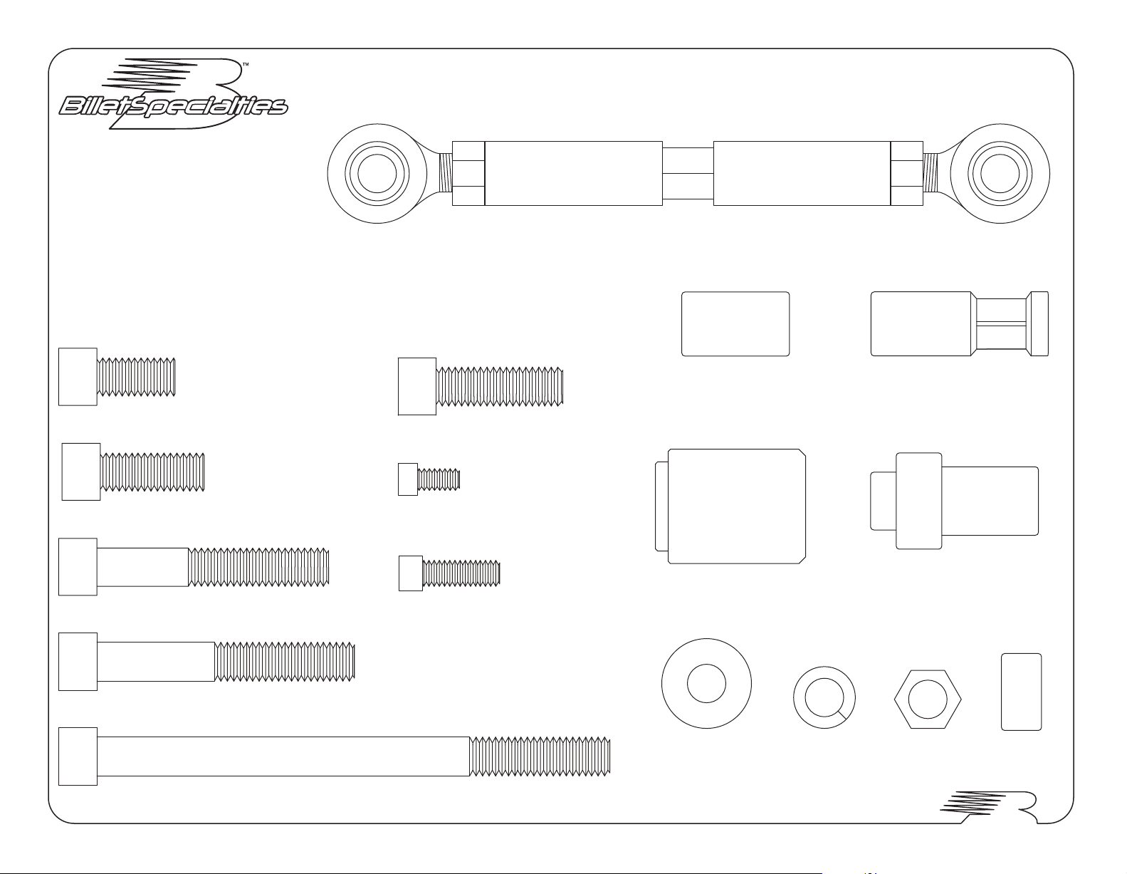
Fasteners shown are for A/C compressor bracket assembly. Refer to Alternator, Power
Steering, & Pulley Installation instructions for additional information.
Turnbuckle Assembly (x1)
3/8-16 x 3/4" Socket Head Cap Screw (x1)
3/8-16 x 1" Socket Head Cap Screw (x2)
3/8-16 x 2-1/4" Socket Head Cap Screw (x1)
3/8-16 x 2-1/2" Socket Head Cap Screw (x3)
3/8-16 x 1-1/4" Socket Head Cap Screw (x1)
#10-32 x 1/2" Socket Head Cap Screw (x6)
1/4-20 x 3/4" Socket Head Cap Screw (x3)
1-1/16" Rear Spacer (x1)
Idler Stand-Off (x1)
x2
3/8 x 7/8" Flat Washer
x1
3/8" Lock Washer
1-3/4" Front Spacer (x1)
Bearing Sleeve (x2)
x1 x1
3/8"-16 Hex Nut
3/16" Load Washer
3/8-16 x 5" Socket Head Cap Screw (x1)
Billet Specialties, Inc. 500 Shawmut Avenue La Grange, Illinois 60526 PH 800.245.5382 Fax 708.588.7181 www.billetspecialties.com
2-18-13
Page 3
FM2213PC/FM2214PC BBC Top Mount Alt, w/ A/C & Power Steering
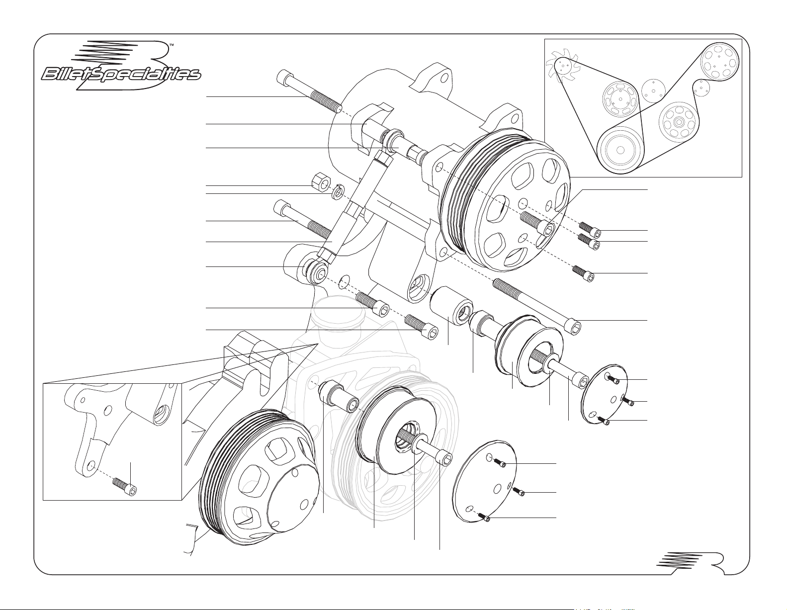
3/8-16 x 2-1/2" S.H.C.S.
1-1/16" Spacer
1-3/4" Front Spacer Nut
Figure 2: BELT PATH
3/8-16 Hex Nut
3/8" Lock Washer
3/8-16 x 2-1/2" S.H.C.S.
Turnbuckle Assembly
3/16" Spacer
3/8-16 x 1-1/4" S.H.C.S.
Thru Bracket To Cylinder Head
3/8-16 x 1" S.H.C.S.
Thru Bracket To Cylinder Head
3/8-16 x 3/4" S.H.C.S.
Thru A/C Bracket To Cylinder Head
Idler Stand-off
Bearing Sleeve
2-1/2" Idler Pulley
3/8" x 7/8" OD Washer
3/8-16 x 2-1/4" S.H.C.S.
3/8-16 x 1" S.H.C.S.
1/4-20 x 3/4" S.H.C.S.
1/4-20 x 3/4" S.H.C.S.
1/4-20 x 3/4" S.H.C.S.
3/8-16 x 5" S.H.C.S.
#10-32 x 1/2" S.H.C.S.
#10-32 x 1/2" S.H.C.S.
#10-32 x 1/2" S.H.C.S.
#10-32 x 1/2" S.H.C.S.
Bearing Sleeve
3-1/4" Idler Pulley
3/8" x 7/8" OD Washer
3/8-16 x 2-1/2" S.H.C.S.
Billet Specialties, Inc. 500 Shawmut Avenue La Grange, Illinois 60526 PH 800.245.5382 Fax 708.588.7181 www.billetspecialties.com
#10-32 x 1/2" S.H.C.S.
#10-32 x 1/2" S.H.C.S.
Page 4

5/16-18 x 3/4" SHCS
FM0209PC BBC Top Mount Alternator Bracket
Tools Required:
1/4” Allen Wrench
5/16” Allen wrench
1/2” Open End Wrench
9/16” Open End Wrench
7/16-14 Thread Chaser (If necessary)
Anti-Seize
We recommend applying Anti-Seize to all threads when assembling bracket.
Recommended Belt: Goodyear 6 Rib #4060460 (46”) or Dayco #5060460 (46.1”)
1) Disconnect battery & remove existing accessory drive brackets.
2) Clean & prep threads in passenger cylinder head (outside hole) and left side of water pump. Run a
7/16-14 thread chaser if necessary. Thread chasers are available at your local auto parts store or tool
dealer and are different from a thread cutting tool.
3) Thread the 7/16-14 x 1-1/4” threaded stud into the outside passenger side cylinder head and finger
tighten. For aftermarket cylinder heads with 3/8“ tapped holes use the included 3/8 to 7/16 adapter.
There should be no more than 5/8” of thread left exposed. ( if more than 5/8” thread is showing, remove
stud and clean out threads then reinstall threaded stud and check again) Apply anti-seize to the
exposed threads on the stud. Also apply anti-seize to the threads of all the remaining fasteners at this
time.
7/16-14 x 1-1/4" Threaded Stud
(Replace with 3/8 to 7/16”adapter
for some aftermarket heads)
3/8-16 x 1" SHCS
3/16" Spacer
3/8-16 x 1-1/4" SHCS
3/8-16 x 3/4" SHCS
3-11/32" Spacer Nut
4) Thread the 3-11/32” spacer nut onto the exposed stud and tighten firmly.
5) Attach the alternator bracket to the water pump with the two 3/8-16 x 3/4” stainless socket head cap
screws and finger tighten.
6) Thread the 3/8-16 x 1-1/4” stainless socket head cap screw through one end of the turnbuckle
assembly and the 3/16” spacer into the water pump boss and tighten firmly. Swing the turnbuckle to the
right and lay to rest out of the way.
7) Attach the alternator ear bracket to the top alternator boss with the 5/16-18 x 3/4” stainless socket
head cap screw and tighten (26 ft./lb.).
8) Place the alternator between the spacer nut and alternator bracket and thread the
3/8-16 x 2-3/4” stainless socket head cap screw through the Alternator bracket & alternator into the
spacer nut and finger tighten.
9) Swing the alternator up into position and match up to the turnbuckle assembly, thread the 3/8-16 x 1”
through the turnbuckle rod end into the alternator ear bracket and
tighten (46ft./lb.).
10) Route belt around alternator, water pump and crank pulleys. Twist turnbuckle by hand until proper
belt tension is achieved. Do not over-tighten belt! Serious damage may occur to the accessory drive
bearings resulting in premature wear.
11) Tighten jam nuts on turnbuckle. Tighten alternator socket head screw (46ft./lb.) Tighten alternator
bracket screws on water pump (46ft./lb.) Re-check belt tension.
12) Reconnect electrical and test run motor. Re-check belt tension after 100 miles.
Billet Specialties, Inc. 500 Shawmut Avenue La Grange, Illinois 60526 PH 800.245.5382 Fax 708.588.7181 www.billetspecialties.com
3/8 to 7/16 Adapter
5/16-18 x 3/4" Socket Head
Cap Screw (x1)
3/8-16 x 1" Socket Head
Cap Screw (x1)
3/8-16 x 1-1/4" Socket Head
Cap Screw (x1)
3/8-16 x 2-3/4" SHCS
Turnbuckle Assembly
7/16-14 x 1-1/4" Threaded Stud
3/8-16 x 2-3/4" Socket Head
Cap Screw (x1)
3/16” Load Washer
3-11/32" Spacer Nut (x1)
3/8-16 x 3/4" Socket Head
Cap Screw (x2)
Page 5

FM0230PC BBC Power Steering Bracket
Tools Required:
5/16” Allen wrench
3/8" Allen wrench
1/2” Open-end wrench
9/16” Open-end wrench
It is recommended that you use the proper tools to remove and install the power
steering pulley. KD Tools P/N2897 puller and installer set or similar will insure
proper pulley service. Some auto parts stores rent out tool sets.
Recommended Belt: Goodyear 6 Rib #4060385 (38.5”)* or Dayco #5060388 (38.8”)*
*If running power steering only
1) Disconnect battery, drain coolant, & power steering fluids. Disconnect coolant & power
steering lines. Remove all existing accessory drive brackets and components from motor.
2) Remove existing power steering bracket and pulley (press on pulleys require the use of a
special puller to avoid damage to power steering pump and pulley – see tool list)
3) Remove water pump, scrape away any existing gasket material.
3/8-16 Thread chaser (If necessary)
7/16-14 Thread chaser (If necessary)
New water pump to engine block gaskets
RTV silicone sealer
Anti-seize
Swing the rear steel bracket up and align with engine block lower mount boss, thread a 7/16-14 x
1-1/2” socket head cap screw through the thin 7/16” ID slide spacer, the rear steel bracket and the
21/32” long rear spacer into the engine block and finger tighten. Note: the spacers have a lip that
locates them in the adjustment slot of the bracket.
10) Thread a 3/8-16 x 1” socket head cap screw through one thin 3/8” ID slide spacer, the aluminum
power steering bracket and one more thin 3/8” ID slide spacer and into the power steering pump.
Finger tighten.
11) Thread the two remaining 3/8-16 x 3/4" socket head cap screws through the aluminum bracket
and into the water pump spacer nuts and tighten firmly (46 ft/lbs).
Do not install top bolt if installing kits with A/C #FM2213PC or #FM2214PC.
12) Install pulley:
For pumps with a keyed shaft – Place the pulley onto shaft, install thrust washer and nut. Tighten
nut.
For Pumps with a press on shaft – Always use a pump pulley installer to push the pulley onto the
shaft. The hub of the pulley should be flush with the end of the pump drive shaft. Follow the
instructions provided with the pulley installation tool.
Do not press or hammer the pulley onto the shaft, this will destroy the pump.
13) For bracket kits that are included with a serpentine conversion kit skip the next step and go on
to step 15
14) Install belt (38-1/2” recommended); adjust belt tension by moving pump in brackets. When
proper belt tension has been achieved, tighten all fasteners firmly. Check belt tension again and
adjust if necessary. Do not over tighten belt! Serious damage may occur to the accessory drive
bearings resulting in premature wear. Go to step 16.
4) Clean and prep threads in cylinder heads, use a thread chaser if necessary. 7/16-14 in engine
block & 3/8-16 in water pump. Thread chasers are available at your local auto parts store or tool
dealer and are different from a thread cutting tool.
5) Thread the 3/8-16 x 2-1/2” threaded studs from the power steering skin board into the driver
side water pump mount holes and tighten. The studs can easily be tightened by threading two
3/8-16 nuts (not included) onto the stud and tighten them against each other to act as a drive
nut. Apply RTV sealer to engine block and water pump.
6) Install gaskets and then water pump. There should be no more than 5/8” of thread left
exposed on studs. If more than 5/8” thread is showing, remove stud(s) and clean out threads
then reinstall threaded stud(s) and check again. Apply anti-seize to the exposed threads on the
studs. Also apply anti-seize to the threads of all the remaining fasteners at this time.
3/8-16 x 3/4" Socket Head Cap Screwx53/8-16 x 1" Socket Head Cap Screw
7) Thread the two 2” long spacer nuts (from the power steering kit) onto the exposed studs with
the hex end out and install the passenger side water pump bolts to complete installation of water
pump. Tighten firmly.
8) Attach the steel three hole power steering bracket to the front of pump with two
3/8-16 x 3/4” socket head cap screws and tighten firmly (46 ft/lb). Attach steel adjustment bracket
to the back of the power steering pump with one 3/8-16 x 3/4" socket head cap screw and finger
tighten.
9) Place pump assembly on motor and align three hole steel bracket with water pump boss by
the spacer nuts. Thread the 1/2-13 x 3/4" socket head cap screw through the bracket and into
the water pump and finger tighten.
Billet Specialties, Inc. 500 Shawmut Avenue La Grange, Illinois 60526 PH 800.245.5382 Fax 708.588.7181 www.billetspecialties.com
15) Only if you have purchased a complete serpentine conversion kit. Align pump so that the fill cap
is level, tighten all fasteners firmly. Install power steering lines and fittings at this time. Return to the
main kit instructions at this time.
16) Install power steering lines and fittings, inspect hoses for kinks or nicks and replace as
necessary. Fill reservoir to the proper level and test run motor. Re-check belt tension and adjust if
necessary. Re-check belt tension after 100 miles.
x1
7/16" Rear Spacer
Length 21/32"
x1
7/16-14 x 1-1/2" Socket Head Cap Screw
3/8-16 x 2-1/2" Threaded Stud
x1
x2
3/8" Slide Spacer
x2
x1
1/2-13 x 3/4" Socket Head Cap Screw
x1
7/16" Slide Spacer
2" Spacer Nut
x2
Page 6

FM0230PC BBC Power Steering Bracket
3/8-16 x 3/4" S.H.C.S.
Thru Bracket To Spacer Nut
Do not install top bolt if installing kit with A/C
*1/2-13 x 3/4" S.H.C.S.
Thru Steel Bracket To Water Pump
(see below)
Billet Aluminum
Power Steering Bracket
7/16-14 x 1-1/2" S.H.C.S.
Rear Steel Bracket
Thru Bracket & Spacers To Block
3/8" Slide Spacer
3/8-16 x 1" S.H.C.S.
To Power Steering Pump
3/8" Slide Spacer
Power Steering Pulley Nut
Thrust Washer
Keyway power steering pulley
shown. Press-on pulley does not
require thrust washer or nut.
7/16" Slide Spacer7/16" Rear Spacer
Hex End Out
2" Spacer Nut
3/8-16 x 3/4" S.H.C.S.
Thru Rear Bracket To Pump
Length 21/32"
3/8-16 x 2-1/2"
Threaded Stud
Billet Specialties, Inc. 500 Shawmut Avenue La Grange, Illinois 60526 PH 800.245.5382 Fax 708.588.7181 www.billetspecialties.com
*1/2-13 x 3/4" S.H.C.S.
To Water Pump
To Water Pump
3/8-16 x 3/4" S.H.C.S.
To Power Steering Pump
Three-Hole Steel Bracket
Page 7

FM3210PC BBC Serpentine Pulley Kit - LWP
ALTERNATOR PULLEY
5/8"
Alternator
Lock Washer
4-40 x 3/8"
Socket Head
Cap Screw (x3)
(x1)
5/8"
Alternator
Hex Nut
(x1)
WATER PUMP PULLEY CRANKSHAFT PULLEY
x3
3/8-16 x 1" Socket Head Cap Screw (x3)5/16-24 x 3/4" Socket Head Cap Screw (x4) 3/8" Belleville Washer
Tools Required:
3/32" Allen wrench
Tools Required:
1/4" Allen wrench
15/16" Socket
Billet Specialties, Inc. 500 Shawmut Avenue La Grange, Illinois 60526 PH 800.245.5382 Fax 708.588.7181 www.billetspecialties.com
Tools Required:
5/16” Allen wrench
 Loading...