

Digital Crane Scale Type LDN
User Manual
Art. Nr. 900030 13. Juni 2006

Index of Contents
Declaration of Conformity 1- 3
1. Safety Instructions 1- 4
2. Keypad 1- 5
3. Key Functions 1- 5
4. Display- Symbols 1- 6
5. Auto Power- Off 1- 7
6. Infrared- Transmitter 1- 8
7. Power Supply of Electronic Device 1- 10
8. Battery Charger / Charging 1- 10
8.1 General 1- 12
8.2 Safety Instructions 1- 12
8.3 Functioning of LED 1- 12
8.4 Putting into Operation 1- 12
8.5 Charge Procedure 1- 13
8.6 Special Instructions to Avoid Sparks 1- 13
8.7 Recommendations for Charging Sealed Lead Acid Batteries 1- 13
9. Accessories 1- 14
9.1 Additional Equipment for Data Transmission 1- 14
9.2 Data Protocols 1- 14
9.2.1 Extended Data Protocol 1- 15
9.2.2 EHP- Standard Data Protocol 1- 16
10. Technical Specifications 1- 17
10.1 Dimensions and Self- Weight 1- 17
10.2 Electrical Properties 1- 18
11. Spare Parts List 1- 19
12. Trouble Shooting 1- 20
12.1 Device Errors
13. Error Detections 1- 21

Declaration of Conformity
Manufacturer EHP-Wägetechnik GmbH
Dieselstrasse 8
D-77815 Bühl (Baden), Germany
declares that the weighing instrument
Digital Crane Scale Type LDN
is conform with following harmonized standards:
EN 45501, EN 50081 part1 according to the provisions of the directive 89/336/EEC
(electromagnetic compatibility, EMC).
EN 60950 according to the provisions of the directive 73/23/EEC (low voltage directive).
EN 45501 / 8.2 non-automatic and EC approved weighing instruments according to the
provisions of the directive 90/384/EEC.
This product is marked with the CE sign.
Bühl, September 2005 Stefan Tisch / Technical Manager
This declaration of conformity is suitable to EN 45014.

1. Safety Instructions
Please read this instruction manual carefully before you set digital crane scale into operation
to prevent injuries and protect your digital crane scale against damages.
More satefy instructions and warnings could be found directly in the corresponding chapter.
...before setting into operation
• Use the EC type -approved version of this digital crane scale only in weather protected
(roof protected) environment, so do not expose it directly sun, rain and snow etc.
• Do not operate this digital crane scale outside the nominal temperature range, e.g. in frost
risk environment (less than -10°C) or high heated areas (over +40°C), in order to perform
best accuracy.
• Check if your crane scale is placed absolutely correct and safe into corresponding hook.
• Respect ACCIDENT PREVENTION REGULATIONS.
• Keep this instruction manual.
...in operation
• Pay attention that scale and load are placed correctly.
• Do not use any solvents for cleaning of the crane scale to prevent defects and damages.
...in case of defects
• Repair work is only allowed to be done by qualified personnel.
• See also chapter TROUBLE SHOOTING and ERROR CODES.
IMPORTANT:
Please be careful with seals and marks on EC type-approved crane scales. If these are
damaged, please inform your local office of weights and measures.
Your digital crane scale works by the principle of a high precision strain gauge sensor system
with subsequent signal processing.
The user/operator is responsible for the safety of this weighing instrument, i.e. perform a
visual control of all tension stressed parts (e.g. ring, hook and shackle) at regular intervals.
In case of visual abrasion of these mounting parts, EHP can offer you a complete technical
check according to the German accident prevention regulations.
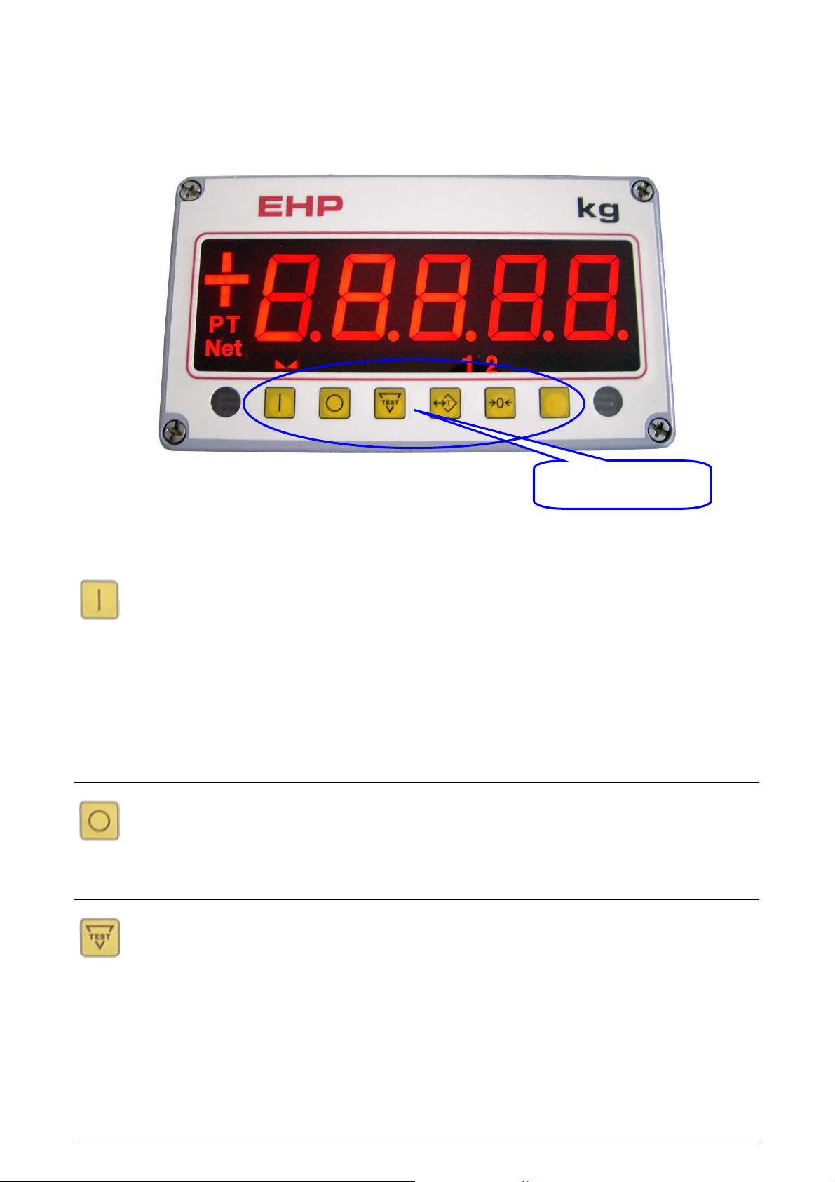
2. Keypad
Figure 2.1: Keypad / Function Keys
3. Key Functions
Function Keys
Function Key for Scales Power-On
• Switches on the scale.
• Activates the automatic display segment check.
• After testing without error display is automatically set to “0“.
Please always switch on scale minimum 5 minutes (warm-up time) before
start of weighing. If preload exceeds 20% of crane scales nominal capacity
(initial zero-setting range) then only +/- sign is displayed. Normal operating
status /weighing mode will be reached again by reducing preload under the
20%-limit and power off-/on-switching.
Function Key for Scales Power-Off
• Switches off the scale.
Power off-/on-switching will reset all crane scale errors (reset function).
Function Key for Test- Routine
Activates during approx. 5 seconds the automatic display segment check
and further particulars are displayed.
For approx. 5 seconds display is flashing:
8 8 8 8 8 (Segment Check)
L A H (Software – Version)
- 1 0.0 4 (Version-No.Release)
- - - 0 1 (Scale No.)
C 0 1 (Frequency Channel No.)
H 0 1 (IR- Transmitter Channel No.)

Function Key to store and to delete Tare Values (TARE- Button)
• (Subtractive) TARE function is activated.
• Current weight value is stored into tare memory.
• Display shows ″0″.
• Net -LED is illuminated.
• Exit by repressing TARE button and GROSS weight is displayed again.
Function Key for Zero-Setting (Zero- Button)
• Sets display to ″0″ (semi-automatic zero-setting device).
• Zero-setting range: -1…+3% of nominal capacity.
Zero-setting outside semi-automatic zero-setting range and also in active
tare weighing mode is not possible. Outside of scales 1/4d-range (a quarter
of verification interval) only +/- sign is illuminated.
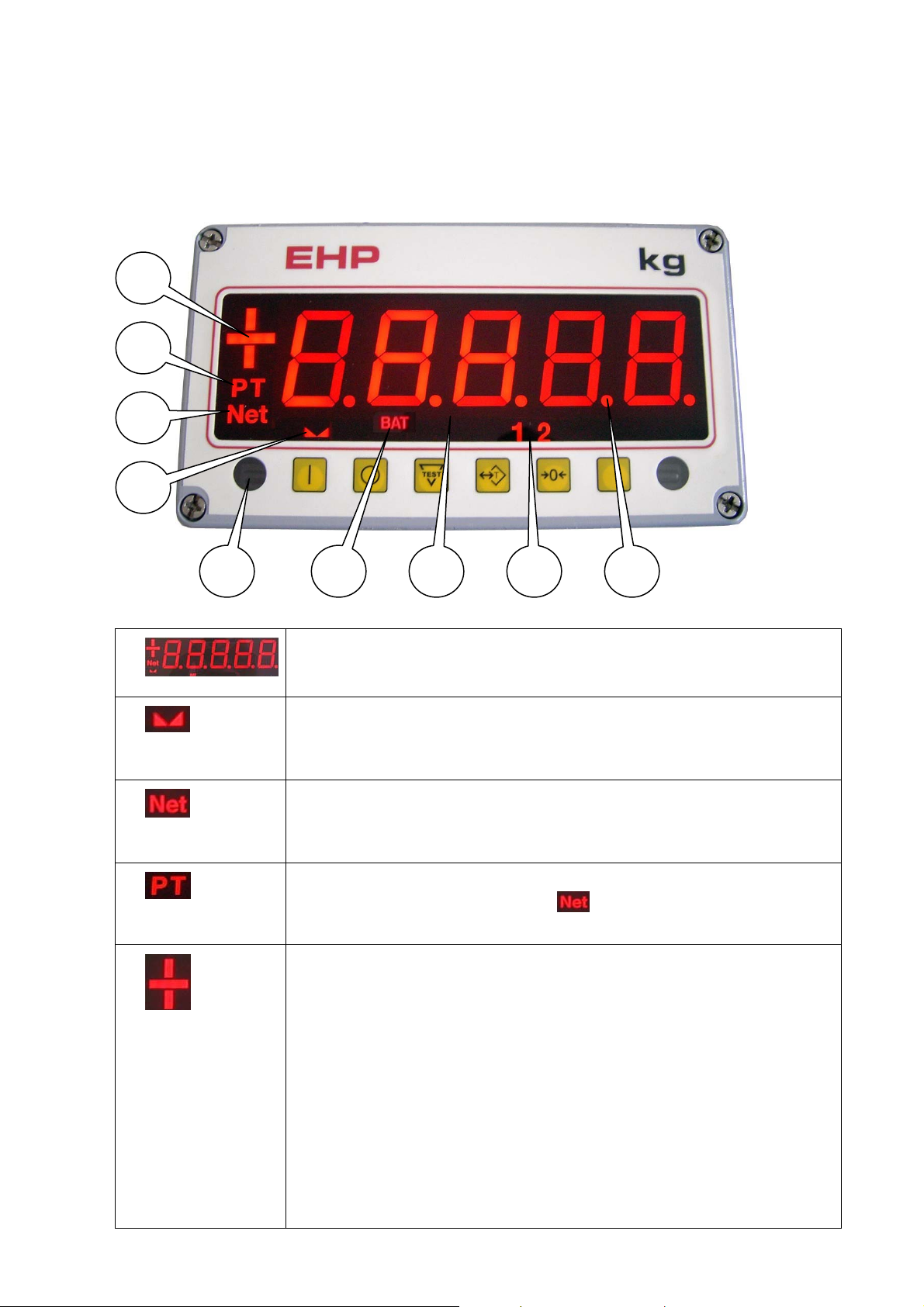
4. Display- Symbols
Figure 4.1: Display
5
4
3
2
8
6 7 1 9
1 -
2 -
3 -
4 -
5 -
Display
Display consists of 5-digit, 7-segments-LED.
Dwell Control Indication
This sign is illuminated when load on crane scales’ hook is motionless
AND a correct weighing result is displayed.
Symbol for Net Weight
This symbol is displayed if a tare value is set. The displayed weight is a
net weight.
Symbol for Pre-Tare
This Symbol is illuminated with the
given. The shown weight value is a net-weight.
Sign- Symbol
Every weight value is displayed combined with its (algebraic) sign.
Æ
Overload Indication:
If crane scale is loaded with more than 2e (2x scales verification
interval) above the nominal capacity range (see model type
indication plate), so display will switch ‘dark’ and only sign-symbol is
displayed.
Normal weighing status is reached again when crane scale is
unloaded (inside permissible weighing range). Example: Capacity
10t: 2x verification interval 5kg = 10kg, i.e. display is switched ‚dark’
at a weight of 10010kg. In respect of SATEFY AND HEALTH please
do not overload crane scale.
- Symbol, if a Tare value was

6 -
Symbol for Decimal Point
Is displayed to indicate position of decimal point.
7 -
8 -
9 -
Symbol for Battery Control
Scales’ accumulator is to charge below a battery voltage of 5.4 volts,
displayed by a flashing
can still work with your instrument for the next 30 minutes (e.g. if it is
not possible to pause your weighing process). By then the battery
needs to be charged. At a battery voltage of 5.3 volts the scale is
switched off automatically to avoid a total discharge and consequently
accumulator damage.
Symbol for the range
Shows range 1 or 2 at Multirange systems.
Receiver (diode) of IR- Transmitter
symbol (empty accumulator). Now you
5. Auto Power-Off
This instrument is equipped with an automatic power-off setting device, which is set default =
deactivated. In scales setup mode you can choose a power-off setting time between 1…99
minutes. To activate this device or changing of setting time, please contact after sales service.
6. Infrared- Transmitter
By means of IR-transmitter you can activate further additional functions beside scale keypad
functions.
Change transmitters’ batteries (4pcs. a 1.5V Type AAA, Micro, LR03, AM4, MN2400) when
operating distance is getting insufficient (less than approx. 20m).

Picture 6.1: IR-Transmitter
14
1
3
5
7
9
13
12
2
4
6
8
10
11
1 -
2 -
3 -
4 -
5 -
6 -
Press button to input and delete tare values (TARE- Button)
This key has same function as on scales’ keypad.
Press button to activate the PRINT- Function (PRINT- Button)
Through this scales display value (plus additional data) will be transmitted via UHF
radio to receiver units (see accessories), e.g. a single print out will be activated on the
integrated printer of TELEDATA receiver unit.
Press button for zero-setting (Zero- Button)
This key has same function as on scales’ keypad.
Press button to activate the ADD- Function (Add- Button)
Press this button if several different single weights within one charge should be
collected resp. added. Scales display value (plus additional data) will be transmitted
via radio to receiver units, e.g. a single weight registration within a total print out will
be activated on TELEDATAs integrated printer.
Non-active, only possible in combination with dual-range scales.
Press button to activate Print Total- Function
Through this scales display value (plus additional data) will transmitted be via UHF
radio to receiver units (see accessories), e.g. a total print out (total of all single weight
values will be activated on the integrated printer of TELEDATA receiver unit (additon
of all single weight registrations transmitted by ADD- Function).
7 -
Press button to activate Test Routine (Test- Button)
This key has same function as on scales’ keypad.

8 -
9 -
10 -
11 -
12 -
Press button for scales’ (remote) power- off
Press this button to switch off the scale by remote control. A re-power-on is possible
by pressing any button of IR- transmitter or by pressing function key
on scales’
keypad. This function could be set deactivated by factory or in scale setup.
Non-active
Non-active
Enter- Button
This press button transfers a code (max. 5 digits) which is entered by numeric keys
together with actual weight value via radio / RS232 (see accessories) to receiver
devices.
Shift- Button
Press this button to activate numeric keys. Now you can input any numbers (max. 5
digit code) between 0…9 (blue numbers).
13-
Symbol for active numeric keys
If this LED is illuminated then you can select the (blue) numbers of IR- transmitter
numeric block (see also Shift- Button).
14-
Transmission- Symbol
Transmitting remote control is displayed by flashing LED.
Note:
If functions: Print, Add and Total are activated by IR-transmitter, their characters are also
displayed on scale. Activating of function keys is now locked during the next approx. 5 seconds in
order to prevent transmitting several commands by mistake.
1- 10

7. Power Supply of Electronic Device
Electronic device is protected by a fast-acting fuse 1A (5 x 20mm DIN 41571).
Crane scale type LDN is powered by a special battery 6 volts.
Picture 7.1: Accumulator with open battery housing
LDN
WARNING:
Avoid setting in false connection or inverse-polarity or connecting of another power supply as
accumulators supplied by manufacturer.
Colour code of supply leads: +/ plus = red, - / minus = black
8. Charger / Charging
It is only allowed to charge the accumulator by original provided EHP- charger, either by using
scales’ charging plug (picture 8.2) or directly (picture 8.1). The charger is equipped with an
electronic charging current limiting so that it is not possible to overcharge the accumulator.
Charging current control is indicated on chargers’ front panel
(All connectors are protected against inverse-polarity).
1- 11

Picture 8.1: Charger and Battery charging
Picture 8.2: Scales’ Plug Socket (Bottom side of scales’ battery housing)
LDN
Charger
6V-Battery
Charging plug to
connect with
scales’ charging
socket
Charging plug to
connect battery
directly
Picture 8.3: Scales’ plug socket with charging plug
Charging plug
Plug socket
Fuse socket
(Fuse 1A, fast-acting,
5x20mm)
1- 12

LDN
8.1 General
The charger is designed in primary switch mode technology. This provides a constant DC voltage
which guarantees a long lifetime of maintenance free sealed lead acid batteries. A holding device
for wall mounting will be found on the back side of the charger.
8.2 Safety Instructions
The charger is especially designed to charge maintenance free lead acid batteries. The charger
housing can only be opened and maintained by authorized personnel. Unqualified opening may
cause damages to charger and will cancel guarantee. Operation with an opened housing is strictly
prohibited. Only a qualified technician is allowed to replace the fuse. The charger can only be
operated if sufficient cooling is assured. The charger can only be operated in closed rooms and
must be protected against moisture.
8.3 Functioning of LED
LED light
red
LED light
green
8.4 Putting into operation
Compare the rated voltage of type plate of charger with the rated voltage of the battery.
The charger will be connected with the plug socket of crane scale to charge the battery I the scale.
To charge the battery outside the scale, an adapting cable is needed (optional) see picture 8.1
8.5 Charge Procedure
When charging the battery, the LED is burning green.
8.6 Special Instructions to Avoid Sparks:
Battery is connected
charger is in loading mode with 1,6A
Battery is charged, charger is in float-charge mode
(max 50 mA) Battery can’t be overloaded.
1. Connect mains supply without battery connection.
2. Disconnect mains after a short period of time.
3. Connect battery with correct polarity.
4. Connect mains supply.
1- 13

LDN
8.7 Recommendations for charging sealed lead acid batteries
Charge/ Discharge
; Before delivery of your crane scale type LDN 6V-battery was already charged for 12 hours and
is therefore instantly ready to operate.
; Charge after each discharge even after partly discharge.
; Never store a discharged battery.
; A completly discharged battery must be charged for min. 16 hours.
; If charging time is below 16 hours for more than 3 days then charge one time for 24 hours to
equalize the poor charging.
; Ambient charging temperature should range between 10°C and 30°C.
Before longer storage periods (2 possibilities)
A: Disconnect battery from charger and store it fully charged.
! CAUTION: Charge battery for min. 36 hours before storage period of 3 months or more!
B: You can leave battery on charge for an unlimited time (trickle charge). It is recommended to
store battery at a cool place.
High ambient temperatures
Charging at temperatures above 30°C is not recommended. Your charger is adjusted with a
charging voltage valid for 20°C.
Low ambient temperatures
Charging below 10°C is not recommended. At low temperatures the available capacity is reduced.
Deep discharge
Try to avoid deep discharges. If a deep discharge occured charge battery as soon as possible for
24 hours.
Maintenance
Wipe battery surface from time to time with a dry and clean cloth.
1- 14

LDN
9. Accessories
9.1 Additional Equipment for Data Transmission
Crane scale type LDN can be equipped with a radio transmitter for data transmission on receiver
units (Teledata, Telebox Plus, Greybox und Large Display) or connection to computer directly:
Large display (*)
Teledata (*)
Greybox
(*) Not available in all countries.
Note:
The connection of additional equipment is under control of a metrological verification, i.e. it is not
allowed to refer received and printed data to a third party.
9.2 Data Protocols
9.2.1 Extended Data Protocol
The extended data protocol (23byte) which is send via radio transmission / serial interface RS232/
V24 (9600 baud, cyclical, approx. 1 transmission per second), has following data format:
1 Startbit
8 Databit
1 Stopbit
No parity
Telebox Plus (*)
1- 15

Byte # ASCII Description
1. S Start sign
LDN
2. 0
1
2
3
4
3. blank (20H)
+
-
4. Digit 5 5th digit (from the right) of weight value
5. Digit 4 4th digit (from the right) of weight value
6. Digit 3 3rd digit (from the right) of weight value
7. Digit 2 2nd digit (from the right) of weight value
8. Digit 1 1st digit (from the right) of weight value
9. B
No decimal point
One position after decimal point
Two positions after decimal point
Three positions after decimal point
Four positions after decimal point
No sign
Plus
Minus
Scale Tare OFF (Gross- Weight)
(e.g. 19520)
(e.g. 1952.0)
(e.g. 195.20)
(e.g. 19.520)
(e.g. 1.9520)
N
10. E
1
2
11. 0
1
12. 0
1
2
3
4
5
6
7
8
Scale Tare ON (Net- Weight)
Single range scale
Range I
Range II
No standstill
Standstill
No button is pressed at IR-transmitter
Button 2 (Print- Button)
Button 4 (Add- Button)
Button 6 (Total- Button)
A
Scale is switched off manually
1- 16

LDN
X
E
C
13. V
H
L
14. (1 – 99) Digit 1 of scale no.
15. (1 – 99) Digit 2 of scale no.
16. (X) Not in use
17. N
J
G
18. Digit 5 5th digit (from the right) of numerical input / IR-transmitter
19. Digit 4 4th digit (from the right) of numerical input / IR-transmitter
Scale is switched off automatically by auto power-off
Transmission error
Test
Battery of scale is full charged
Battery of scale – pre-warning
Battery of scale – discharged/ empty
No overload
Overloaded
Out of initial zero-setting range
20. Digit 3 3rd digit (from the right) of numerical input / IR-transmitter
21. Digit 2 2nd digit (from the right) of numerical input / IR-transmitter
22. Digit 1 1st digit (from the right) of numerical input / IR-transmitter
23. 03 H End of block (03 Hex)
9.2.1 EHP- Standard- Protocol
The standard-protocol (18 byte) is compatible completely to the transmission with additional EHPreceiver units (Teledata, Telebox Plus and Large Display). In comparison to the extended protocol
byte #18… #22 (numerical code) are missing.
1- 17

10. Technical Specifications
10.1 Dimensions and Self-Weight
Dimensions in millimeter
LDN 0,5 / 1 / 2
228
60
ø16
168135
100
LDN
LDN 5
228
90
ø22
256135
141
Net
Bat
28 237
475
2
1
29
Self- weight: 12kg
Net
Bat
43
654
2
1
45
237
Self- weight: 18kg
LDN 20
173
LDN 10
842
140
ø36
290
Net
38
195
Bat
2
1
227
ca.1045
110
ø32
Net
195
Bat
2
1
64
290
61
330
56
255
66
330
Self- weight: 35kg
Self- weight: 48.5kg
Technical variations may cause the specifications to change without notice
1- 18

LDN
10.2 Electrical Properties
Power supply of electronic device 6V DC maintenance-free lead acid battery 14.4Ah
Minimal battery voltage 5.3V DC
Power supply of IR- transmitter 4pcs. a 1.5V Type AAA, Micro, LR03, AM4, MN2400
Operation distance of IR- transmitter approx. 35m with angle < 20°
Minimal operation time of scale 80 hours
Power supply of battery charger 230V AC, 50/60Hz
Nominal charging time < 12 hours
Maximum number of verification intervals 2500 divisions (acc. EC type-approval certificate)
Nominal temperature range -10°C...+40°C
Temperature range -10°C...+50°C
EEC protection class IP 54
1- 19

LDN
11. Spare Parts List
For spare parts please contact your next representative service center or manufacturers’ after
sales service.
Part No. Part
69009 Battery charger 6V / 1,6A
69268 Battery 6V / 12Ah
70972 IR – transmitter
72061 Electronic pc-board LDN
52525 Fast-acting fuse 1A, 5 x 20mm, DIN 41571
72204 Front panel LDN
56639 Protection shield LDN 0.5-5t
61578 Protection shield LDN 10t
72237 Protection shield LDN 20t
72215 Ram protection LDN 10t / 20t
72216 Ram protection LDN 5t
66319 Load cell LD 0.5-2t
74690 Load cell LD 5t
69355 Load cell LD 10t
72270 Load cell LD 20t
1- 20

LDN
12. Trouble Shooting
Repair work on digital crane scale LDN is only allowed by qualified
technical personnel.
If the advice does not bring any success, please contact the after sales service.
12.1 Device Errors
Fault Cause Corrective
Display is dark No power Please check if scale is
switched on.
Please check if battery is
charged.
Please control the fuse.
(Only approved version)
Display shows for a short time ’+’
sign after switching on.
(Only non-approved version)
Display flashes
Display shows only the ‘+’ sign High overload Reduce the weight to a
It is not possible to switch off the
scale.
Scale can not set to zero.
Scale is out of initial zerosetting range
Scale is overloaded Reduce the load inside the
Electronic error Remove fuse and insert it
Scale is outside zero-setting
range
Scale is set into tare
weighing mode, Net- LED is
illuminated.
Switch off scale, unload the
scale and switch on again.
nominal weighing range (see
type plate on right side of the
scale)
permissible value
again, switch on scale.
Please reduce the load inside
the zero-setting range.
Press TARE- Button again to
quit tare weighing mode.
1- 21

LDN
13. Error Detection
Automatic error diagnosis routines verify cyclically the proper function of the weighing instrument
and ensure a faultless operation; a permanent visual control is not necessary anymore. In case of
an error, it will be displayed in form of an error code (see table). Therefore weighing is no longer
possible. Scale will automatically be switched off after approx. 5 seconds.
Error Code Cause Corrective
02 Amplifier input voltage is to
low.
03 Amplifier input voltage is to
high.
04 AD-Converter Error Switch off the scale and switch
Switch off the scale and switch
on again.
Please contact after sales
service.
Switch off the scale and switch
on again.
Please contact after sales
service.
on again.
Please contact after sales
service.
1- 22

EHP Wägetechnik GmbH
Dieselstraße 8 • D-77815 Bühl (Baden)
Tel. +49 (0) 7223 93660 • Fax +49 (0) 7223 30140
E-mail: info@ehp.de • www.ehp.de
servizio post-vendita after sales service service après-vente
Kundendienst servicio post-venta serviço pós-venda
Tel. +49 (0) 7223 9366 0 • Fax +49 (0) 7223 30140
 Loading...