

Page 1
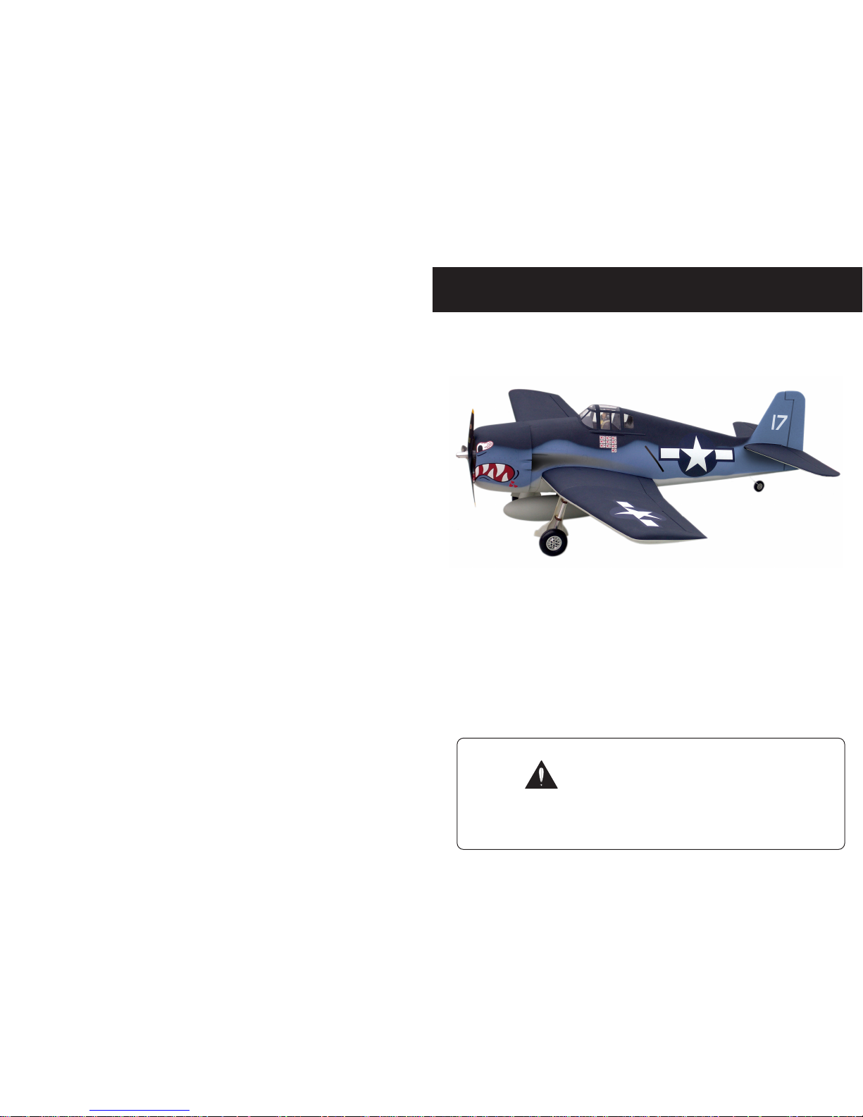
Specification:
Len gth :1365 m m(54")
Win g Sp an :18 29 mm(7 2")
Win g Are a :64.8 3 sq. d m
6. 99 sq. ft
Win g L oadin g :100 .3 g/sq . dm
32 .9 oz/s q. ft
Fly ing Weigh t : 6.5 kg(14 .3 l bs)
Rad io :6ch & 8 serv os
Eng ine :120 4 -cycle
SAFETY PRECAUTIONS
Before start,please carefully read the explanations!
F6F Hellcat
INSTRUCTION MANUAL
First-time builders should seek advice from people having building
experience.If misused or abused,it can cause serious bodily injury
and damage to property.
Fly only in open areas and preferably at a dedicated R/C flying site.
We suggest having a qualified instructor carefully inspect your
airplane before its first flight.Please carefully read and follow all
instructions included with this airplane,your radio control system
and any other components purchased separately.
(The people under 18 years old is forbidden from flying this model)
This R/C airplane is not a toy!
Page 2
4-cycle .120
15″X7
6
86
6
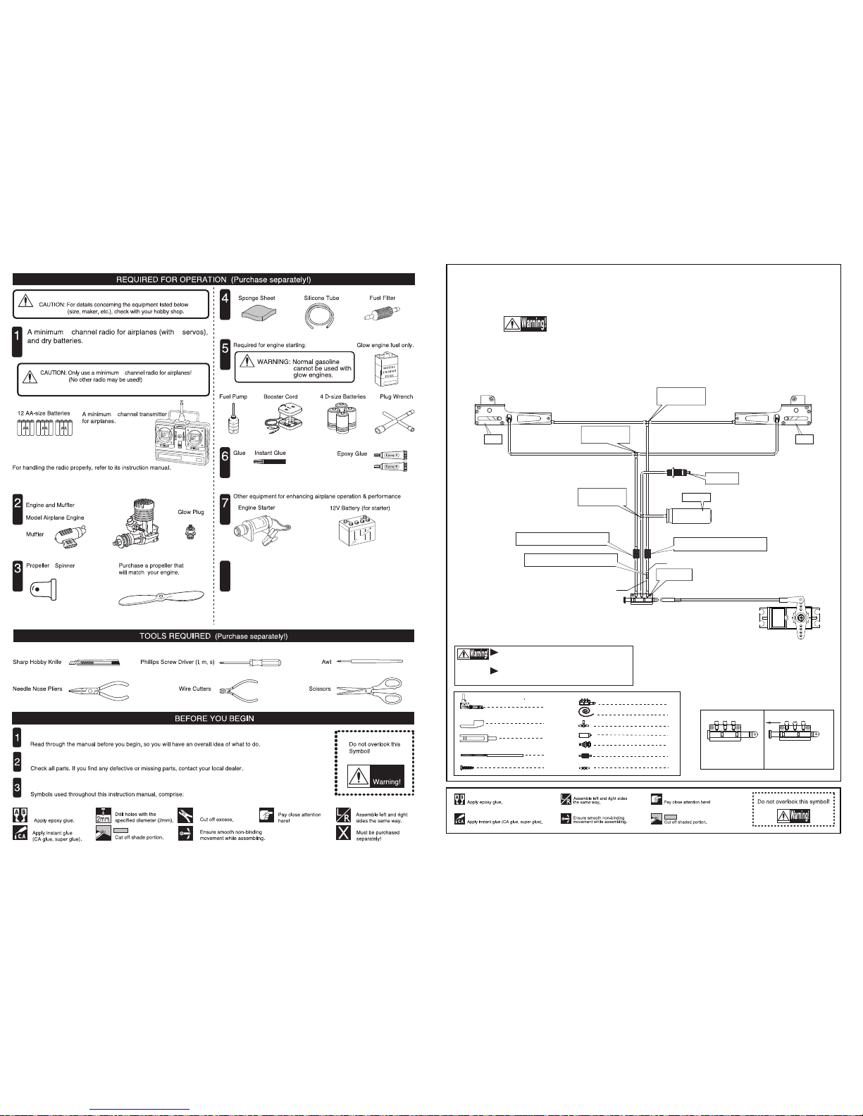
6 channel radio for aiplane is highly recommended for this model.
9
Optional parts: rubber wheel with metal hub,
oleo struts and retracts system.
Spinner nut
Air tank
Switch
Air inlet
3-way
pressure inlet
3-way
pressure inlet
3-way
pressure inlet
Push plug to the far end
to make gear down
Pull out length of 8mm
to make gear up
Air valve
Air valve
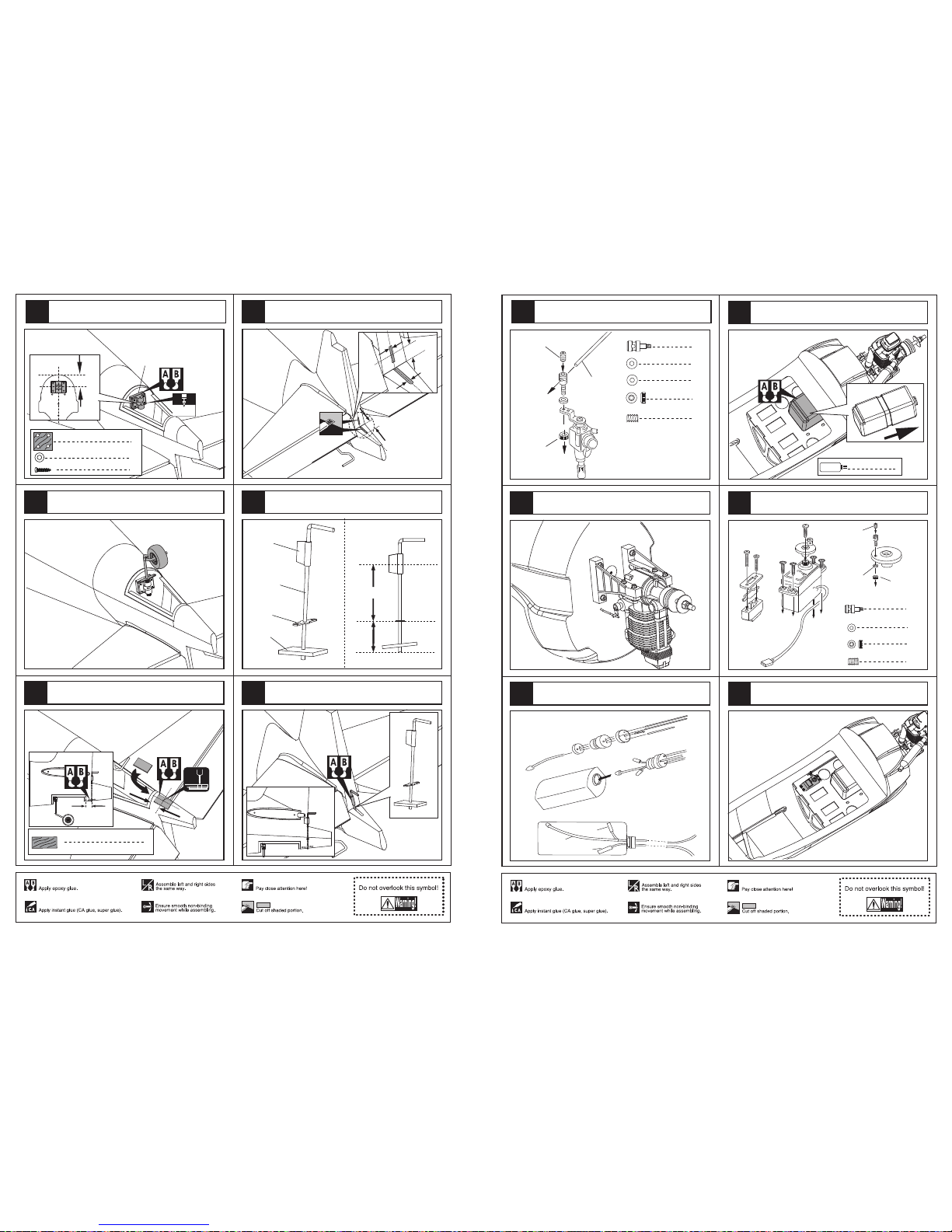
Make sure to assemble retracts as instructed below.
Two wheel retract system
Quick release connector
Quick release connector
Pressure reduction inlet
Strut
Strut
3-way pressure inlet
3
Pressure reduction inlet
1
1
Air tank
1
Air inlet
2
1
1
Air line (3000mm)
2
Quick release connector
Strut
( 90 )
Switch
Clevis
Rod (2X300mm)
1
1
1
Retainer
TP Screw(2x14mm)
2
Ø1.7mm
Ø0.2mm
Pleas notice the inner diameter for each
side of the pressure reduction inlet.
Please insure the sealing of the retract
system before flight .
Page 3
Make sure hinges are
mounted in the same line.
Securely glue together. If coming off during flights, you 'll
lose control of your airplane which leads to accidents!
Aileron
1mm
Trailing
edge
Make sure they are in
the right position while
installing.
6
Pin hinge(24x24mm)
8
6
2
2
2
4
2
4
2
2
Clevis
Rod (2x300mm)
Retainer
TP Screw (2.3x12mm)
Wooden Block(20x20x8mm)
Servo tray(68.5x56.5x2mm)
Pin hinge(24x24mm)
Screw (3x40mm)
Washer(3x15mm)
2
Washer(3x15mm)
Lock Nut (3mm )
Clevis
Retainer
Rod (2x300mm)
Screw (2x10mm)
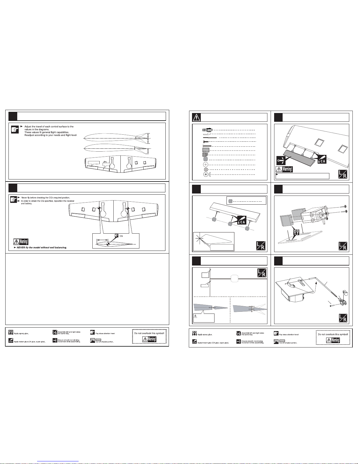
Install the servo as the illustration below
Install the nylon control horn and connect the linkage.
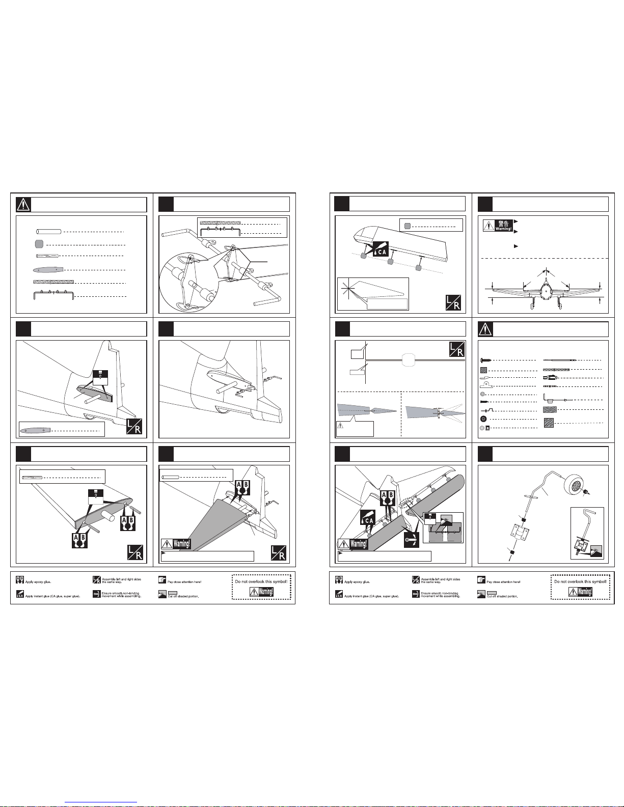
Apply instant type CA glue to aileron and pin hinge.
Keep some space about 1mm width between
aileron and trailing edge.
Assemble the aileron to main wing with instant type CA glue.Be careful
to ensure the moving parts of the hinges are able to move freely.
1
2
3
4
5
1
Accessory list for the coming installation steps.
117mm
20mm
20mm
30mm
AILERON
FLAP
FLAP
AILERON
Side View
Adjustment.
The centre of the Gravity.
82
81
16
Page 4
8
10
2
2
2
4
4
2
Clevis
Rod (2x300mm)
Retainer
TP Screw (2.3x12mm)
Wooden Block(20x20x8mm)
Servo tray(68.5x56.5x2mm)
Screw (3x40mm)
TP Screw (2.3x12mm)
TP Screw (2.3x12mm)
8
TP Screw (2.3x12mm)
2
2
Washer(3x15mm)
2
Washer(3x15mm)
Lock Nut (3mm )
1
Rib template (2mm ply)
4
Wood dowel (6x30mm)
Main wing joiner
2
2
Metal wire (1.8x290mm)
1.5mm
3mm
Rod (2x300mm)
Clevis
Washer(3x15mm)
Washer
Lock Nut (3mm )
Screw (3x40mm)
6mm
1
Rib template (2mm ply)
2mm ply
8
TP Screw (2.3x12mm)
Pin hinge(36x20x1mm)
6mm
4
Wood dowel (6x30mm)
2mm ply
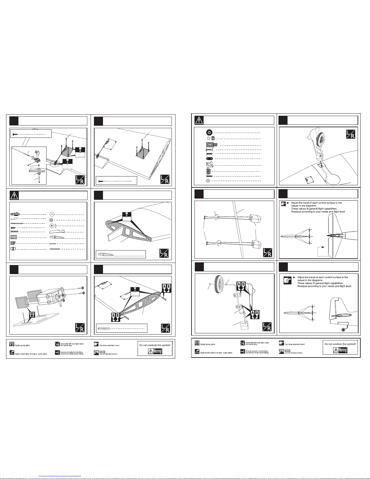
Secure the servo.Install the nylon control horn
and connect the linkage.
Secure the servo with servo tray.
According to the rib template drill holes to the
relevant position in the mid wing.
Install the servo as the illustration below
According to the rib template drill holes to the wing
root and epoxy wood dowel in them.
6
8
9
10
2
Accessory list for the coming installation steps.
7
Top view
Side View
30mm
30mm
RUDDER
Top view
Position for
right diagram.
ELEVATOR
Side View
25mm
25mm
Wooden Block(43x28x26mm)
1
Gear door
2
4
Collar (5mm)
Wheel (100mm)
Landing gear(5mm)
2
1
12
6
TP Screw (3x20mm )
Landing gear straps
4
TP Screw (2.6x14mm)
Washer (3x6mm)
12
2
Wooden Block(25x15x13mm)
TP Screw (2.6x14mm)
Collar (5mm)
Wooden supporter
Collar (5mm)
Epoxy the wheels to the wings steadily.
TP Screw (3x20mm )
Wooden Block
Landing gear straps
Landing gear(5mm)
Fix the wooden block to appropriate position
in the landing gear.
Epoxy the wheel pants to the wooden blocks steadly. Adjustment.
Adjustment.
76
15
77
78
79
80
Accessory list for the coming installation steps.
Page 5
5mm
70mm
55mm
2
Fibre tube(5x30mm)
Fibre tube(5x30mm)
55mm
24mm
5mm
2
PVC Part
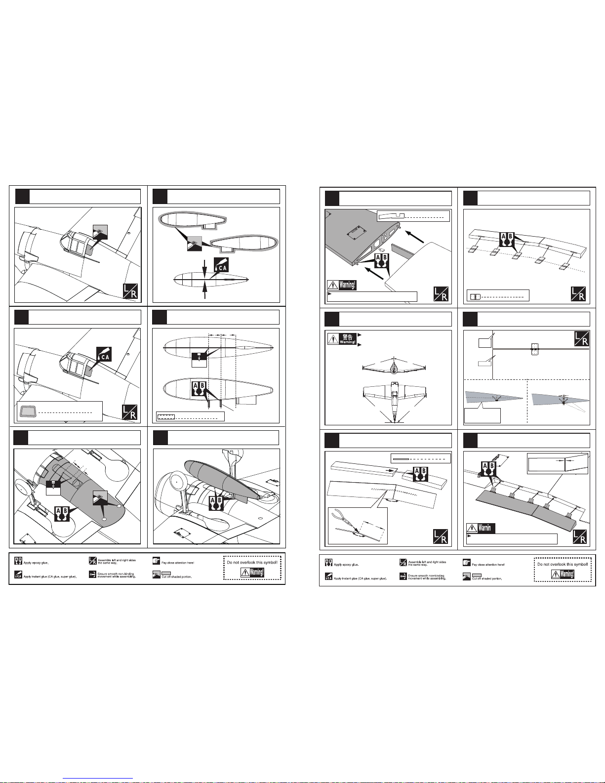
Cut off the shaded portion carefully from the fuselage.
(This step decided by customers themselves)
Glue the PVC parts to the fuselage carefully.
(This step decided by customer themselves)
Epoxy the bottom cover to mid wing and drill holes to
appropriate position.
Drill holes to appropriate position in the bomb
and epoxy fibre tube in them.
Trim the shaded portion carefully and glue the
two parts hardly together with CA glue.
Epoxy the drop tank to the bottom cover.
72
14
74
71
73
70
75
Main wing joiner
2
Securely glue together. If coming off during flights, you 'll
lose control of your airplane which leads to accidents!
B=B'
A=A'
A`
A
B`
B
10
Pin hinge(24x24mm)
2
Metal wire (1.8x290mm)
172º
140mm
172º
Flap
1mm
Make sure they are in
the right position while
installing.
Trailing
edge
Make sure to glue securely.
If not properly glued, a failure in flight may occur.
Securely glue together.If coming off during flights,
you'll lose control of your airplane which leads
to accidents!
Securely glue together. If coming off during flights, you 'll
lose control of your airplane which leads to accidents!
2mm
Epoxy the main wing to the mid wing through the
main wing joiner and wood dowel.
Assemble the wings.
Keep some space about 1mm width between
trailing edge and flap.
Connect the flap by a bended metal wire.
Epoxy the pin hinges to the flaps tightly.
Epoxy the flaps to the wings as illustration.
12
13
14
11
16
3
15
Page 6
Retracts strut
LockNut(4mm)
Bushing (8x4mm)
Bushing (8x4mm)
Note:rubber wheels oleo struts
and retracts are optional.
Rod (2x300mm)
Clevis
Washer(3x15mm)
Washer
Lock Nut (3mm )
Screw (3x40mm)
Screw (2x10mm)
3mm
2
Wood dowel (6x50mm)
2
2
Blind Nut (6mm)
Screw (6x50mm)
1
Gear door
2
Wheel (100mm)
8
2
TP Screw(3x20mm)
8
LockNut (4mm)
4
Wooden Block
Wooden Block
4
Bushing (8X4mm)
Washer(3x6mm)
Retainer
Rod (2x300mm)
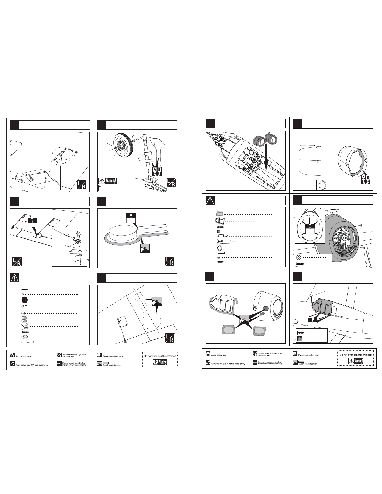
Secure the servo.Install the nylon control horn
and connect the linkage.
Assemble the wheel and the gear door to the retract.
Take care to assemble the whell pants to right sides.
Connect the retainer and the servo arm with
linkage as below.
Cut away the surplus parts of plastic cover
carefully along the shaded line.
5mm
Cut away the shaded portion for assembling
the gear house.
18 20
21
4
17
Accessory list for the coming installation steps.
19
6
TP Screw (2.3x8mm)
Ply (15x15x3mm)
6
1.5mm
TP Screw (2.3x8mm)
1
Former
TP Screw(3x20mm)
TP Screw(3x20mm)
Washer (3x6mm)
5
5
1.8mm
6
TP Screw (2.3x8mm)
1
Canopy
Ply (15x15x3mm)
6
1
1
Drop tank
Bottom cover
1
Former
2
Fibre tube(5x30mm)
TP Screw(3x20mm)
Washer (3x6mm)
5
5
2
PVC Part
Cut the shade portion off the canopy and
cowling carefully.
Install the receiver and the battery in the fuselage.
Assemble the cowling to fuselage with screw.
Epoxy the former to appropriate position in the cowling.
155mm
Epoxy the plies in the inside of the fuselage as below and
assemble the canopy to the fuselage with TP screw.
65
66
68
69
13
67
Accessory list for the coming installation steps.
Page 7
4
4
Clevis
Copper joiner
4
4
Screw (2x10mm)
Nut (2mm )
4
Washer(2x5mm)
Steel wire
Copper joiner
Lock Nut (2mm )
Screw (2x10mm)
Ball joint
Washer(2x5mm)
Add a rubber ring to the
clevis for insuring safety
Throttle servo
Switch servo
Elevator servo
Rudder servo
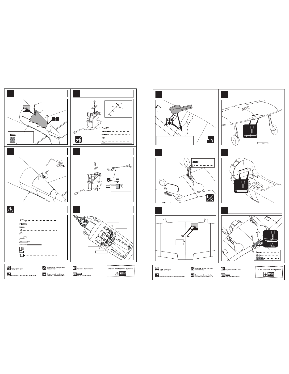
Install the servo of swith.
Install the servo.
The sketch map when the servos install completion.
TP Screw (2.3x12mm)
1.5mm
8
TP Screw (2.3x8mm)
Ply (15x15x3mm)
8
Collar
4
4
Clevis
Copper joiner
4
4
Screw (2x10mm)
Nut (2mm )
4
Washer(2x5mm)
Clevis
1
Rod (2x300mm)
1
1
Retainer
1
Ring
1
1
Air tank
Switch
Assemble the tail fuselage cover with TP screw.
Assemble wheel to tail under carriage with collar.
61
63
62
64
12
60
Accessory list for the coming installation steps.
160mm
50mm
Center
line
6mm
2
Wood dowel (6x50mm)
100mm
100mm
18mm
6mm
6.2mm
Blind Nut
2
2
Blind Nut (6mm)
Screw(6x50mm)
Reinforcement Plate
1
Assemble the wings to the fuselage with screw.
Drill holes at relevant position in the fuselage.
Drill two holes for pulling out the servo extension line.
Drill holes at appropriate position in the mid wings
and fix the wood dowel in them.
TP Screw (3x20mm)
8
TP Screw (3x20mm)
8
Washer(3x6mm)
Assemble the retract to the mid wing.
The sketch maps when the gear up and down.
Epoxy the gear house to the relevant position.
Note:Please fix the air tube before
assemble the wheel house to the wing.
23
22
25
26
5
24
27
Page 8
B=B'
A=A'
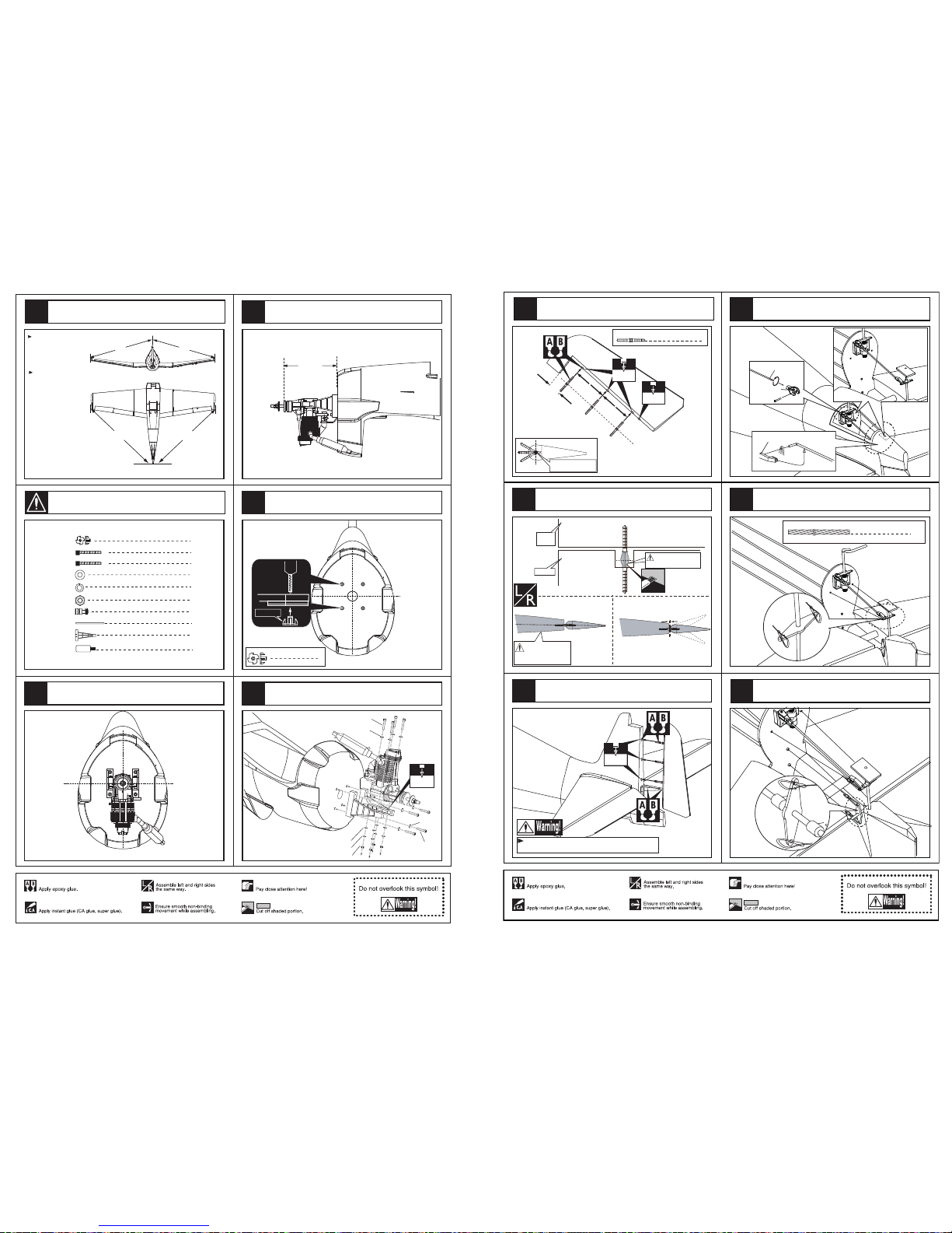
Drill 6.2mm holes at the place
of main wing.
Install the wing to the fuselage
with 6x50mm screws as shown
in the diagrams below.
A`
A
B`
B
4
Blind Nut (4mm)
1
Engine mount (68x105mm)
Linkage Stopper
4
4
12
4
Washer(4x8mm)
Screw (4x35mm)
Spring Washer (4mm)
Nut (4mm)
2
4
Screw (4x25mm)
2
Plastic tube (2x400mm)
Fuel tank (550cc)
1
160 mm
In case of 2-cycle & 4-cycle engine.
The side view of the engine install completion.
The front view of the engine install completion.
5.2mm
Blind Nut
Blind Nut (4mm)
4
Drill four holes and set blind nut at diameter in the
firewall for mounting the engine.
Washer (4x8mm)
Washer (4x8mm)
Washer (4x8mm)
Screw (4x35mm)
Screw (4x25mm)
Nut (4mm)
Spring Washer (4mm)
4mm
Install the engine carefully.
Assemble the wings.
29
30
31
28
6
32
Accessory list for the coming installation steps.
Retainer
Rod (2x300mm)
Clevis
2
Steel wire (0.5x3000mm)
Make sure hinges are
mounted in the same line.
3
Pin hinge(2.5x48mm)
2.5mm
27mm
75mm
75mm
2.5mm
Securely glue together. If coming off during flights, you 'll
lose control of your airplane which leads to accidents!
1mm
Rudder
Tailing
edge
Cut away the rubber tube when
the epoxy glue dried.
Make sure they are in
the right position while
installing.
Keep some space about 1mm width between the
tailing edge and the rudder.
Apply instant type CA glue to rudder and pin hinge
Epxoy the rudder to the fuselage steadily.
3mm
The sketch map for connecting the arms in tail
landing gear and the arm for rudder.
The sketch map of steel wire assembled to the arms
for rudder.
The sketch map of steel wire assembled to the arms
of U-style wire.
56
57
58
59
60
55
11
Page 9
28mm
Metal arms
Rod (3x130mm)
Pin hinge
Ply (35x20x3mm)
29mm
51mm
5mm
2mm
18mm
TP Screw(3x20mm)
Washer (3x6mm)
4
4
Ply (3mm)
2
1.8mm
Ply (6mm)
40mm
25mm
3mm
Ply (35x20x3mm)
1
25mm
The sketch map of assembling the wheel steeling
mount to appropriate position in the fuselage.
The sketch map when tail wheel assemble completion.
Epoxy a ply to appropriate position in the fuselage
as belowand drill a hole in right point.
Trim slots carefully in the fin and tail fuselage as below.
Notice the position of pin hinge,Metal armon the
the metal wire.
Epoxy the pin hinge to the vertical fin as below.
50
51
52
53
54
10
49
Fuel tank (550cc)
1
Fuel supply line
Fuel spray line
Air pressure line
Set Screw (3x4mm)
Set Screw (2mm)
Rod (2x400mm)
Set Screw (2mm)
Washer (2mm)
Linkage Stopper
1
1
1
1
Washer (4x8mm)
4
Set Screw (3x4mm)
Mount the fuel tank to the fuselage.
Assembly of the fuel tank.
Notice the position of the lines in the tank.
Linkage Stopper
Washer (2mm)
Washer (2mm)
Nut (2mm)
Set screw (3x4mm)
Washer (
2mm
)
Set screw (3x4mm)
1
1
1
1
Install the throttle servo.
Assemble the throttle servo to the fuselage.
Assemble the accelerator push rod to the engine.
The sketch map when the engine install completion.
34
35
36
33
38
7
37
Page 10
4mm
4
Wood dowel (4x30mm)
2
1
Steel wire (0.5x3000mm)
Steel wire (0.5x3000mm)
U-style wire (3mm)
Securely glue together. If coming off during flights, you 'll
lose control of your airplane which leads to accidents!
U-style wire (3mm)
1
Stab joiner(12x230mm)
6
Pin hinge(24x24mm)
4
Matal douel (4x30mm)
1
Rib template (2mm ply)
2mm ply
2
1
Steel wire (0.5x3000mm)
U-style wire (3mm)
4mm
1
Rib template (2mm ply)
According to the rib template drill holes to the tail of
fuselage as below.
1
Stab joiner(12x230mm)
Drill two holes at the stabilizer root base on rib template
and epexy the wood dowel in them.
connect the fullarm on elevator with steel wire as below.
Install the U-style wire to appropriate position in the tail of
fuselage and assemble the stabilizer to fuselage as illustration.
Drill holes to appropriate position in the stabilizer .
39
40
41
42
43
8
Accessory list for the coming installation steps.
Collar
Tail landing gear
Collar
Collar
3
1
Nose arm(3mm)
Collar (3mm)
3
1
1
Tail landing gear(3mm)
Tail wheel (45mm)
1
Retainer
Rod (2X257mm)
1
TP Screw(3x20mm)
Washer (3x6mm)
4
4
2
Steel wire (0.5x3000mm)
1
Clevis
1
Tail landing gear(3x105mm)
Pin hinge(2.5x48mm)
Ply (35x20x3mm)
1
8
TP Screw (2.3x8mm)
Ply (15x15x3mm)
8
Elevator
1mm
Trailing
edge
Make sure they are in
the right position while
installing.
Securely glue together. If coming off during flights, you 'll
lose control of your airplane which leads to accidents!
3mm
Make sure hinges are
mounted in the same line.
6
Pin hinge(24x24mm)
Glue the elevator to the stabilizer by CA glue
and epoxy glue.
Apply instant type CA glue to elevator and pin hinge.
Keep some space about 1mm width between
elevator and tailing edge.
Ply (6mm)
1
B'
A
A'
B
Make sure to glue securely.
If not properly glued, a failure in flight may occur.
Temporarily fasten down the main wing and
check its correct position.
Securely glue together.If coming off during flights,
you'll lose control of your airplane which leads
to accidents!
A=A'
B=B'
Assembly of the stabilizer.
Assemble the tail landing gear to the wheel steeling
mounts as below.
46
47
48
9
44
Accessory list for the coming installation steps.
45
 Loading...