

Page 1
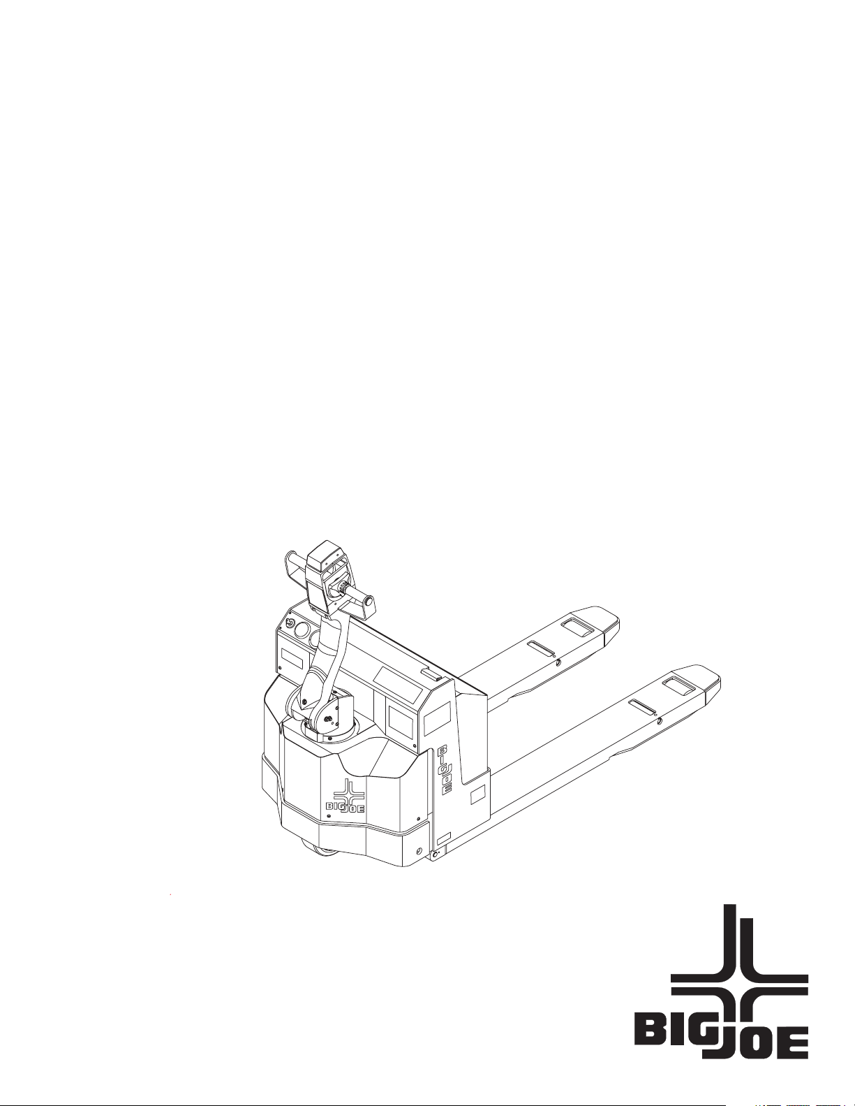
PPT 45 Series
Self-Propelled,
Pallet Lift Truck
Serial Numbers 373323
through 374781
Operation
Maintenance
Repair Parts List
PPT0104-901336 i
Manual No. 901336
Page 2

SAFETY SECTION
SAFETY WARNINGS
Throughout this manual the following Warning Words
will be used in conjunction with important operator
instructions. The listing below shows the level of the
warnings.
DANGER
DANGER
This is the highest level statement. Failure to follow the
listed instructions will most likely result in severe injury
or death.
WARNING
WARNING
This is a statement of serious hazard. Failure to follow
the listed instructions could place the individual at risk
of serious injury or death. The statements used with
this level of warning deal with a safe operating
procedure. If the procedure is ignored, the possibility of
personal injury may exist.
Energy Isolation
During the servicing of the PPT 45 it may be required to
work with and around electrical power. In most cases,
the truck will be serviced with the batteries
disconnected. However, some of the service
procedures may require working with the battery
connected or within the battery charger. As required,
the lockout and tagout of the main power supply will be
required and will need to be indicated as shown below.
Lockout: The placement of a lockout device on an
energy-isolating device (breaker panel, etc.), in
accordance with an established procedure, ensuring that the energy- isolating device and the equipment being controlled cannot be operated until the
lockout device is removed.
Tagout: The placement of a tagout device on an
energy- isolating device (circuit breaker), in accordance with an established procedure, to indicate
that the energy-isolating device and the equipment
being controlled cannot be operated until the
tagout device is removed.
An appropriate locked out and tagged out power supply
is shown in the illustration below. The tag, as
suggested by the illustration below, should accompany
lockout devices used for this safety function.
CAUTION
CAUTION
The statements used with this level of warning deal
with a safe operating procedure. If the procedure is
ignored, the possibility of personal injury may exist.
IMPORTANT
IMPORTANT
This type of statement is used to draw attention to a
procedure that needs to be followed to prevent
machine damage.
ii PPT0104-901336
Page 3

Table of Contents
SECTION 1 DESCRIPTION
1-1. INTRODUCTION .........................................................................................................................................1-1
1-2. GENERAL DESCRIPTION ..........................................................................................................................1-1
1-3. NAMEPLATE ............................................................................................................................................... 1-1
1-4. SAFETY FEATURES................................................................................................................................... 1-2
1-5. OPTIONS..................................................................................................................................................... 1-2
SECTION 2 OPERATION
2-1. GENERAL.................................................................................................................................................... 2-1
2-2. OPERATING PRECAUTIONS .................................................................................................................... 2-1
2-3. GENERAL CONTROL OPERATION...........................................................................................................2-2
2-4. DRIVING AND STOPPING PROCEDURES ...............................................................................................2-2
2-4.1. Standard Travel ................................................................................................................................ 2-2
2-4.2. Creep Travel..................................................................................................................................... 2-2
2-5. BELLY-BUTTON SWITCH. (Figure 2-1)...................................................................................................... 2-3
2-6. STEERING ARM RETURN SPRING...........................................................................................................2-3
2-7. LIFT AND LOWER CONTROLS..................................................................................................................2-3
2-8. LOADING AND UNLOADING ...................................................................................................................... 2-3
2-9. PARKING..................................................................................................................................................... 2-3
SECTION 3 MAINTENANCE
3-1. GENERAL.................................................................................................................................................... 3-1
3-2. OPERATOR DAILY CHECKS .....................................................................................................................3-1
3-3. MONTHLY AND QUARTERLY CHECKS....................................................................................................3-1
3-4. BATTERY CARE .........................................................................................................................................3-1
3-4.1. General............................................................................................................................................. 3-1
3-4.2. Battery Removal ............................................................................................................................... 3-3
3-4.3. Testing and Charging of Lead Acid Battery ......................................................................................3-3
3-5. LUBRICATION............................................................................................................................................. 3-4
SECTION 4 ADJUSTMENT AND REPAIR
4-1. GENERAL.................................................................................................................................................... 4-1
4-2. PART NUMBER IDENTIFICATION .............................................................................................................4-1
4-3. STEERING ARM AND CONTROL HEAD ................................................................................................... 4-1
4-3.1. Belly-Button Switch Adjustment........................................................................................................4-1
4-3.2. Potentiometer Testing and Adjustment ............................................................................................4-2
4-3.3. Control Head Switch Replacement...................................................................................................4-3
4-3.4. Steering Arm.....................................................................................................................................4-4
4-3.5. Steering Arm Spring Replacement ................................................................................................... 4-5
4-3.6. Electrical Control Cable Replacement.............................................................................................. 4-6
4-4. BRAKES ......................................................................................................................................................4-8
4-4.1. Brake Pad Adjustment ...................................................................................................................... 4-8
4-4.2. Brake Pad Replacement...................................................................................................................4-9
4-4.3. Replacement of Brake Assembly ...................................................................................................4-11
PPT0104-901336 iii
Page 4

4-4.4. Replacement of Dead-Man Switch ................................................................................................. 4-12
4-4.5. Replacement of Creep Travel Switch .............................................................................................4-12
4-4.6. Replacement of Control Arm Shock Absorber................................................................................ 4-13
4-5. DRIVE MOTOR, TRANSMISSION, DRIVE WHEEL, AND PIVOT TUBE ASSEMBLY .............................4-13
4-5.1. Drive Motor Servicing. .................................................................................................................... 4-13
4-5.2. Inspect and replace worn brushes as follows:................................................................................ 4-13
4-5.3. Inspect commutator assembly........................................................................................................ 4-14
4-5.4. If the motor needs to be replaced, remove it from the transmission as follows:............................. 4-15
4-5.5. Transmission Assembly Removal. ................................................................................................. 4-16
4-6. BASE, FRAME AND FORK SECTION ......................................................................................................4-17
4-6.1. General........................................................................................................................................... 4-17
4-6.2. Load Wheel Replacement .............................................................................................................. 4-17
4-6.3. Frame Assembly: Fork Section and Lift Linkage Repair and Replacement. .................................. 4-18
4-7. ELECTRICAL............................................................................................................................................. 4-20
4-7.1. Battery Removal and Replacement................................................................................................ 4-20
4-7.2. Battery Cable Assemblies Replacement. ....................................................................................... 4-20
4-7.3. Transistor/Contactor Panel............................................................................................................. 4-21
4-7.4. Horn Replacement.......................................................................................................................... 4-22
4-7.5. Battery Charger. ............................................................................................................................. 4-23
4-7.5.1. 12V Light Duty Gel-Cell Batteries................................................................................. 4-23
4-7.5.2. Medium Duty 6V Battery Pack...................................................................................... 4-23
4-7.5.3. Heavy Duty 24V Steel Case Flooded Cell Industrial Battery (Not shown)....................4-23
4-7.6. BATTERY DISCHARGE INDICATOR............................................................................................ 4-24
4-7.6.1. Battery Discharge Indicator Replacement. ................................................................... 4-24
4-7.7. HOURMETER. ............................................................................................................................... 4-25
4-7.7.1. Hour meter Replacement. ............................................................................................4-25
4-7.8. KEYSWITCH. .................................................................................................................................4-25
4-7.9. Wire Harness Testing. .................................................................................................................... 4-25
4-8. HYDRAULICS............................................................................................................................................ 4-27
4-8.1. Line and Fitting Replacement......................................................................................................... 4-27
4-8.2. Hydraulic Pump, Motor, and Reservoir Assembly. ......................................................................... 4-27
4-8.3. Lift Cylinder Removal. .................................................................................................................... 4-29
4-8.4. Lift Cylinder Repair. ........................................................................................................................ 4-29
4-8.5. Hydraulic Pressure Adjustment. ..................................................................................................... 4-30
4-9. DECALS AND TRIM. ................................................................................................................................. 4-30
4-9.1. Painting Requirements. .................................................................................................................. 4-30
4-9.2. Decals and Plates. ......................................................................................................................... 4-30
SECTION 5 OPTIONS
5-1. COLD CONDITIONING PACKAGE.............................................................................................................5-1
iv PPT0104-901336
Page 5

SECTION 6 TROUBLESHOOTING
6-1. TROUBLESHOOTING CHART ...................................................................................................................6-1
6-2. Contactor Testing ........................................................................................................................................6-3
6-2.1. Contactor Testing .............................................................................................................................6-3
6-2.2. Switch Testing. ................................................................................................................................. 6-3
6-3. TRANSISTOR CONTROLLER TROUBLESHOOTING ...............................................................................6-5
6-3.1. Circuit Operation...............................................................................................................................6-6
6-3.2. GENERAL SYSTEM CHECKOUT. ..................................................................................................6-9
6-3.3. ADJUSTMENT ...............................................................................................................................6-10
6-4. DIAGNOSTICS. ......................................................................................................................................... 6-11
6-4.1. Programmer Diagnostics ................................................................................................................ 6-12
6-4.2. Diagnostic History...........................................................................................................................6-12
6-4.3. Test the Fault Detection Circuitry ................................................................................................... 6-12
6-5. Maintenance .............................................................................................................................................. 6-12
6-5.1. Cleaning .........................................................................................................................................6-13
6-5.2. Transistor Control Electrical Panel Maintenance............................................................................6-13
6-6. Troubleshooting ......................................................................................................................................... 6-13
6-6.1. Check for Power to the Controller ..................................................................................................6-14
6-6.2. Check for Contactor Operation and Keyswitch Input (KSI) ............................................................6-14
6-6.3. Check Potentiometer Circuitry........................................................................................................ 6-14
6-6.4. Check for controller output .............................................................................................................6-15
SECTION 7 PARTS LIST
7-1. Control Head Assembly ...............................................................................................................................7-2
7-2. Steering Arm ................................................................................................................................................7-6
7-3. Power Section Parts ....................................................................................................................................7-8
7-4. Transmission, Motor and Brake Assembly ................................................................................................7-12
7-5. Drive Motor Repair Parts ...........................................................................................................................7-14
7-6. Base and Frame Parts ............................................................................................................................... 7-17
7-7. Fork Section Parts ..................................................................................................................................... 7-18
7-8. Hydraulic Cylinder Parts ............................................................................................................................7-21
7-9. Hydraulic Cylinder Parts ............................................................................................................................7-22
7-10. Battery Installation Parts............................................................................................................................ 7-24
7-11. Battery Charger Assembly......................................................................................................................... 7-26
7-12. Contactor Panel Assembly Parts ............................................................................................................... 7-28
7-13. Charger Circuit Board ................................................................................................................................ 7-30
7-14. Load Wheels .............................................................................................................................................. 7-31
7-15. Optional Equipment ...................................................................................................................................7-32
7-15.1.Cold Conditioning ...........................................................................................................................7-32
PPT0104-901336 v
Page 6

vi PPT0104-901336
Page 7
Section 1
DESCRIPTION
1-1. INTRODUCTION
This publication describes the PPT 45 lift truck
manufactured by Big Joe Manufacturing Company,
Lincolnwood, Illinois 60646. Covered in this manual are
operating instructions, planned maintenance
instructions, lubrication procedures, corrective
maintenance procedures and a complete parts list with
parts location illustrations.
By following the recommendations contained in this
manual, you will receive many years of dependable
service from your Big Joe lift truck.
1-2. GENERAL DESCRIPTION
The self-propelled PPT 45 truck, Figure 1-1, lifts and
transports payloads up to 4500 pounds on rigid forks.
The forward and reverse motion is controlled by either
of two control levers mounted on the control head.
Stopping and turning is controlled by the steering arm.
Lift and Lower is controlled by pushbuttons located on
the control head. The battery-powered lift truck is quiet
and without exhaust fumes.
The reversible DC motor propels the lift truck in forward
or reverse direction throughout the available speed
range. The PPT 45 lift truck can be driven with forks
raised or lowered. The lift truck must be operated and
stored in an area where it will be protected from the
elements.
1-3. NAMEPLATE
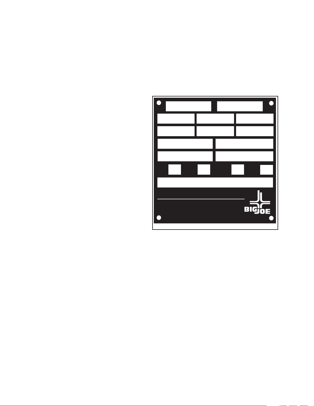
The nameplate (Figure 1-2) is the key for identifying
many of the features of your lift truck. It provides
information such as:
• Model number
• Serial number
• Maximum capacity, load center, and maximum
lift height
• If applicable, alternate capacity, load center,
and maximum lift height
• Truck weight without battery
• Minimum weight of battery
• Battery voltage
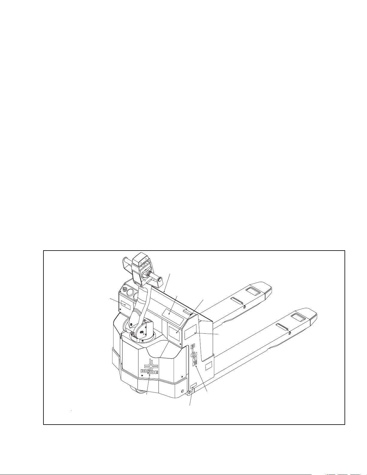
Refer to Figure 1-1 for serial number location, if the
nameplate becomes lost or illegible.
Logo Plate
And Insert
Big Joe Logo
Figure 1-1. PPT 45 Orientation
No Rider
Decal
Operationing
Instructions
S/N Location
Access Panel
Caution Decal
3 places
Name
Plate
Big Joe Logo
I-7001
PPT0104-901336 1-1
Page 8
1-4. SAFETY FEATURES
The PPT 45 is designed and engineered to provide
maximum safety for operator and payload. Some of the
safety features incorporated into the design are:
• Deadman brake to apply mechanical brake and cut
off drive power when the steering arm is released.
• Belly-button switch to reverse truck should the
operator accidentally pin himself against a wall or
obstruction when backing up in slow speed.
• All control functions automatically return to 'OFF"
when released.
• Externally accessible quick-disconnect battery plug
within operator's reach.
• Separately fused control circuits and power circuits.
• Lift carriage backrest to help stabilize the load.
• Readily accessible HORN button.
• Slip-resistant hand grips to provide a firm hand
hold for operator.
• Flow control valve regulates maximum load lowering speed within prescribed limits.
• Relief valve maintains hydraulic pressure within
prescribed limits.
• High visibility color scheme of truck provides visual
alert of trucks presence.
1-5. OPTIONS
Big Joe offers options and accessories for the PPW 45
lift truck such as:
• Cold conditioning package
• Load backrest extension
• Skid adapter
•Casters
MODEL NO
MAX CAP LB/KG
MAX CAP LB/KG
TRUCK WT LESS BATTERY LB/KG.
TRUCK WT WITH BATTERY LB/KG.
TRUCK
TYPE
COMPLIES WITH THE APPLICABLE REQUIREMENTS OF ANSI B56.1 AND OSHA ST
BIG JOE MANUFACTURING COMPANY
WISCONSIN DELLS, WISCONSIN
BATTERY
TYPE
US PATENT NO. 4,444,428
AUSTRALIAN PATENT NO. 537,987
LOAD CTR IN/NM LIFT HT IN/MM
LOAD CTR IN/NM LIFT HT IN/MM
CERTIFIED
SERIAL NO.
BATTERY MIN WT LB/KG
BATTERY MAX WT LB/KG
TRUCK
TYPE
ANDARDS
53965
Figure 1-2. Name Plate
I-7002
1-2 PPT0104-901336
Page 9
Section 2
OPERATION
2-1. GENERAL
This section gives detailed operating instructions for
the PPT 45 lift truck. The instructions are divided into
the various phases of operations, such as operating lift,
driving, and stopping. Routine precautions are included
for safe operation.
2-2. OPERATING PRECAUTIONS
WARNING
Improper operation of the lift truck may result in
operator injury, or load and/or lift truck damage.
Observe the following precautions when
operating the PPT 45 lift truck.
1. Do not operate this truck unless you have been
trained and authorized to do so and have read all
warnings and instructions in this manual and on the
truck.
2. Do not operate this truck until you have checked its
condition. Give special attention to Tires and
Rollers, Horn, Battery, Controller, Lift System,
Brakes, Steering Mechanism, Guards and Safety
Devices.
3. Operate truck only from designated operation
position. Wear foot protection. Do not carry
passengers.
4. Observe applicable traffic regulations. Yield right of
way to pedestrians. Slow down and sound horn at
cross aisles and wherever vision is obstructed.
5. Start, stop, travel, steer and brake smoothly. Slow
down for turns and on uneven or slippery surfaces
that could cause truck to slide or overturn. Use
special care when traveling without load, as the
risk of overturn may be greater.
6. Always look in direction of travel. Keep a clear
view, and when load interferes with visibility, travel
with load or lifting mechanism trailing.
7. Use special care when operating on ramps-travel
slowly, and do not angle or turn. Travel with lifting
mechanism or load downhill.
8. Do not overload truck. Check nameplate for
capacity and load center information.
9. Before lifting, be sure load is centered, forks are
completely under load, and load is as far back as
possible against load backrest.
10. Do not handle loads that are higher than the load
backrest unless load is secured so that no part of it
could fall backward.
11. When leaving truck, neutralize travel control. Fully
lower lifting mechanism and set brake. When
leaving truck unattended or storing for prolonged
periods, disconnect battery.
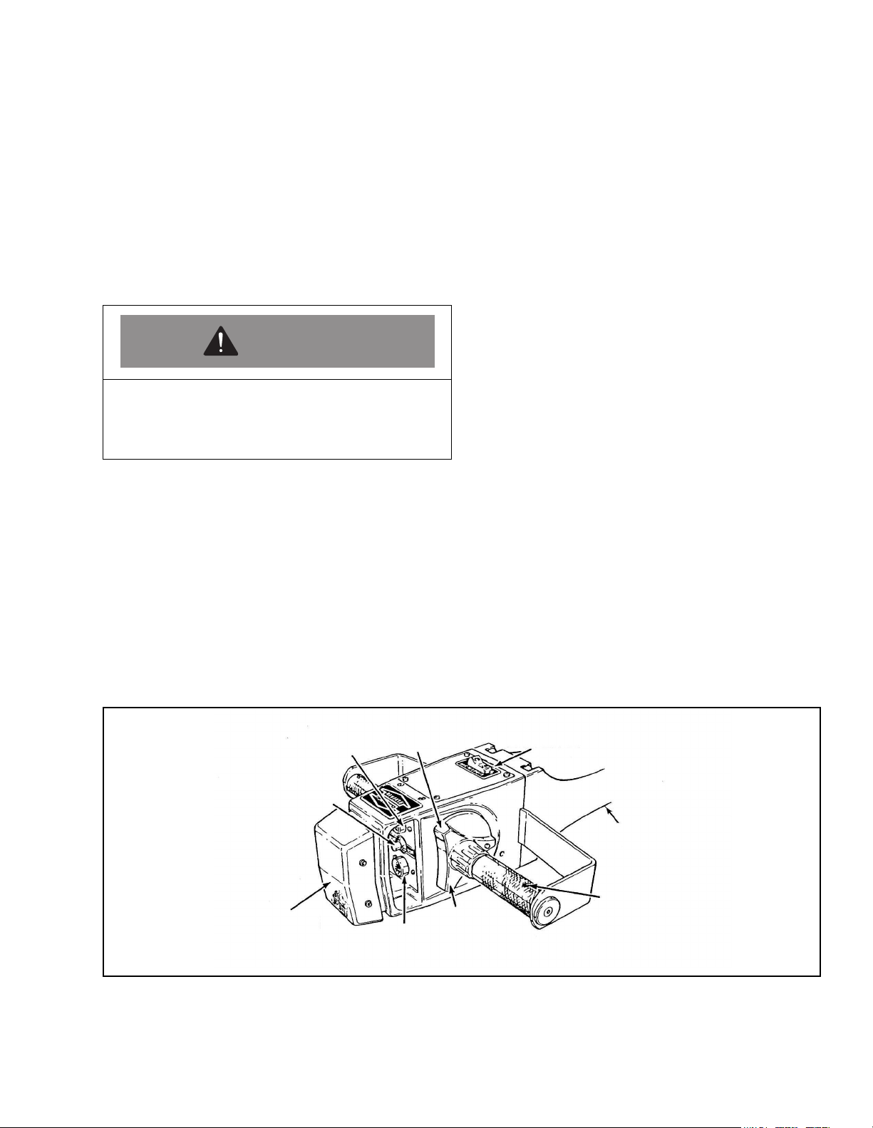
Reverse
Speed
Control
Fork
Lower
Control
Forward
Speed
Control
High Speed
CutOu t Switch
I 7003
Steering
Arm
If Rotating Grips
Are Preferred,
Remove Pins
I-7003
Belly Button
Switch Guard
Horn
Pushbutton
Fork
Raise
Control
Figure 2-1. Steering Control
PPT0104-901336 2-1
Page 10
2-3. GENERAL CONTROL OPERATION
The speed control (Figure 2-1), located on each side of
the control head, provides fingertip control for driving
the truck. Rotating, or pressing the speed control
downwards moves the truck in the FORWARD
direction. As the speed control is pressed, it closes
electrical contacts for first speed, or creep, in the
forward direction. Pressing the speed control farther
increases the speed of the truck. The speed control is
infinitely variable, which means that the farther the
control is pressed, the faster the truck will move.
NOTE: The truck is equipped with a High Speed
Cutout Switch, located on the control head,
higher travel speeds will be available. With this
switch in the OFF position, standard travels
speeds are available. Place the switch in the
ON position to enable the highest travel
speed.
Rotating or pressing the speed control upwards moves
the truck in the REVERSE direction. The upper portion
of the speed control controls the reverse speeds in the
same manner.
The pushbutton switches, located behind the belly
button switch guard, activate the lift-lower controls and
the horn.
4. To slow down or stop, release the speed control
and lower or raise the steering arm to the
horizontal or vertical position. In those positions,
the brake pads apply pressure to the brake disc
slowing or stopping the truck.
NOTE: Procedures for movement in reverse are
the same as in the forward direction.
5. To travel in reverse, lower steering arm to a
comfortable position above horizontal and slowly
press the speed control upwards.
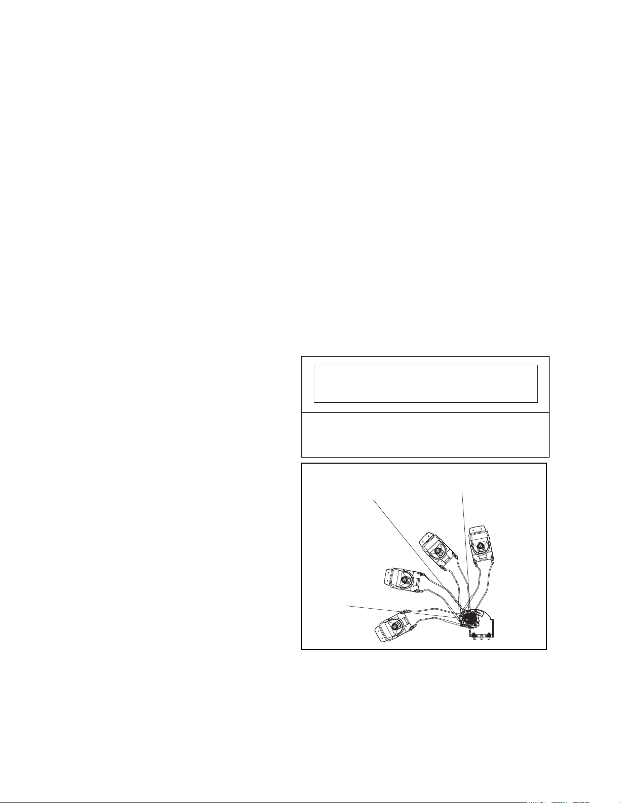
2-4.2 Creep Travel
1. Creep, or the slowest travel speed, is available in
both forward and reverse.
2. Lower the handle from the vertical position until
you hear a "click" which indicates that the controls
are energized. See Figure 2-2.
3. Rotate the speed control for either forward or
reverse travel.
IMPORTANT
The brake is applied by lowering or raising the steering
arm. When the steering arm is lowered or raised
approximately half way the brakes are partially applied.
When the steering arm is raised completely vertical,
the brakes are fully applied. (See Figure 2-2) All
traction control power is shut off when the brake is
engaged. When the steering arm is in the upright
position, the brake acts as a parking brake. Deadman
braking occurs when the handle is released and spring
action raises it to the upright position.
2-4. DRIVING AND STOPPING PROCEDURES
2-4.1 Standard Travel
1. If equipped, turn on the key switch. Grasp the grips
of the steering arm so that the speed control can
be comfortably operated by either thumb.
2. Lower the steering arm to a comfortable position
above horizontal to disengage the brake and to
energize the electrical circuits.
3. To move forward (with load trailing), slowly press
the speed control downwards. Press the forward
speed control farther to increase speed. If
engaged, the High Speed cutout switch will disable
the highest travel speeds.
With the control handle in the creep position, creep
speed will be the only speed available no matter how
far the speed control is rotated.
Brake Dis-engaged,
Brake Dis-engaged,
All Controls Energized
Brake Fully Engaged
Controls De-energized
Forward/Reverse
Creep Speed Enabled,
All Controls Energized
Brake Fully Engaged
Controls De-energized
I-7004
Figure 2-2. Brake Arm Actuation
2-2 PPT0104-901336
Page 11

2-5. BELLY-BUTTON SWITCH. (FIGURE 2-1)
The belly-button switch (Figure 2-1) minimizes the
possibility of the driver being pinned by the steering
arm while driving the lift truck forward in slow speed. If
the guard presses against the operator while the lift
truck is being driven forward, the guard actuates a
switch, which changes the direction of the lift truck to
reverse direction in low speed.
2-6. STEERING ARM RETURN SPRING
The steering arm return spring automatically raises the
steering arm to the upright position when the steering
arm is released. If the steering arm snaps up abruptly,
or does not fully raise, the steering arm return spring
requires adjustment. Return truck to maintenance for
adjustment.
2-7. LIFT AND LOWER CONTROLS
Lift/Lower Control buttons are located on the steering
control head, behind the belly button switch guard.
(Figure 2-1)
• To lift the forks, push in LIFT button and hold until
forks reach desired height.
• To lower the forks, push in LOWER button and
hold until forks descend to desired height.
2-8. LOADING AND UNLOADING
1. Move truck to location where load is to be picked
up.
2. Using the BACKWARD speed control, move truck
backward into position so forks are within pallet or
skid, the load is centered over the forks and as far
back toward the backrest as possible.
3. Raise forks to lift load.
4. Drive to area where load is to be placed.
5. Move truck to position load at the delivery location.
6. Lower the load until it rests squarely in place and
the forks are free.
7. Using the FORWARD speed control, slowly move
the truck straight forward to remove forks from
pallet.
2-9. PARKING
When finished with moving loads, drive truck to its
maintenance or storage area. If equipped, turn off the
key switch. If the lift truck is designed to use a remote
charger, disconnect battery cable from the truck
receptacle and connect it to the chargers receptacle. If
the lift truck is equipped with an internal charger,
connect the power cable to the charger plug to charge
the batteries.
Charge batteries as necessary. Refer to battery care
instructions, Section 3-4.
PPT0104-901336 2-3
Page 12

NOTES:
2-4 PPT0104-901336
Page 13

Section 3
MAINTENANCE
3-1. GENERAL
Maintenance includes both the operator daily check
procedures and scheduled maintenance, which must
be performed by a qualified service technician. Any
problems noted during the operator's daily inspection
or the monthly and quarterly scheduled maintenance
procedures must be corrected by a qualified
maintenance technician.
3-2. OPERATOR DAILY CHECKS
Table 3-1 is a checklist identifying both visual and
operational checks that must be performed by the
operator on a daily basis to ensure the safety of the
equipment. Optional items are noted as such.
WARNING
• If the truck is found to be in need of repair,
unsafe, or contributes to an unsafe
condition, report it immediately to your
designated authority.
• If during operation, the truck becomes
unsafe, report it immediately.
• Do not operate the truck until it has been
restored to safe operating condition.
• Do not make any unauthorized repairs or
adjustments.
3-3. MONTHLY AND QUARTERLY CHECKS
Table 3-2 is a monthly and quarterly inspection and
service chart based on normal usage of equipment.
Normal use is eight hours per day, five days per week
for a total of 40 hours per working week. If the lift truck
is used in excess of forty hours per week, the
frequency of inspection and service should be
increased accordingly.
3-4. BATTERY CARE
WARNING
• Hydrogen gas that vents from lead acid
batteries can explode. Do not smoke, use an
open flame, or create an arc or sparks in the
vicinity of the batteries. Ventilate well when
in an enclosed space and when charging.
• The batteries contain SULFURIC ACID, which
causes severe burns. Do not get acid in eyes,
on the skin or clothing. In case of contact,
flush immediately and thoroughly with clean
water. Obtain medical attention when eyes
are affected.
3-4.1 General
The life of the batteries can be extended by giving them
proper care. Perform a daily check of the batteries
whether or not the equipment is in daily use.
IMPORTANT
• DO NOT overcharge the batteries or battery life
will be shortened.
• DO NOT allow batteries to become completely
discharged (specific gravity 1.150 or less for
flooded cell batteries. Maintenance free battery
charge level is not measured by specific gravity).
This will also greatly shorten battery life.
PPT0104-901336 3-1
Page 14

Table 3-1. Daily Checks
VISUAL CHECKS
ITEM PROCEDURE
DAMAGE Check for bent, dented or broken parts.
LEAKS Check drive unit and hydraulic system.
TIRES AND WHEELS Check drive wheel and load wheels for wear, damage, binding, etc.
FORKS Check for bends and misalignment.
CABLES AND HOSES Check that they are in place and not damaged.
BATTERY If your unit is equipped with flood cell batteries, check the water level and vent
caps for damage or plugging.
IMPORTANT: If the lift truck is equipped with maintenance free batteries, DO
NOT attempt to remove battery caps.
BATTERY CONNECTOR Check for cracks, burns and for tight connections with truck receptacle.
GUARDS Check load backrest, covers and guards for damage.
SAFETY DEVICES Check that warning labels, data plates, etc. are in the same condition as
originally equipped.
FRAME AND SERVICE
COVER
Check for damaged paint, cracks in welds or other damage.
OPERATIONAL CHECKS
HORN Check for sound.
STEERING Check for binding or excessive play. Excessive play will be indicated by a
physical shifting or movement of the transmission.
TRAVEL Check all speed ranges, forward and reverse. No unusual noise should be
present.
HYDRAULIC CONTROLS Check lift and lower for binding or unusual noises, etc.
BRAKES Check that brake stops truck within a safe distance and works smoothly. Check
dead-man brake by releasing handle.
HOUR METER Check for proper operation.
PARKING BRAKE Make sure it holds the truck in place.
BATTERY CHARGE
INDICATOR
BELLY BUTTON SWITCH In an open and unrestricted area check for proper operation.
Check that battery discharge indicator is on "full" or the specific gravity of
batteries, as checked with a hydrometer, indicates full charge.
3-2 PPT0104-901336
Page 15
Table 3-2. Monthly and Quarterly Inspection and Service Chart
NOTE: The following service checks should be performed by a qualified service technician.
INTERVAL INSPECTION OR SERVICE
Monthly Clean drive motor and check condition of commutator, brushes, and springs (Section 4-5).
Monthly Clean hydraulic pump motor and check condition of commutator, brushes, and springs
(Section 4-8).
Monthly Check brake for proper operation.
Monthly Check load wheels for wear. A poly load wheel must be replaced if worn to within 1/16 inch
of hub. Check for separation from hub.
Monthly Check drive wheel for wear. A poly drive wheel must be replaced if wheel is worn to within 1
inch of hub. Check for separation from hub.
Monthly Inspect wiring for loose connections and damaged insulation.
Monthly Inspect contactor for proper operation.
Monthly Check deadman brake switch for proper operation.
Quarterly Check lift cylinder for leakage.
Quarterly Check for excessive jerking of steering arm when stopping or starting.
Quarterly Check brake pads for wear. Brake pads must be replaced when air gap can not be
adjusted to tolerances shown in Section 4-4 Brakes.
3-4.2 Battery Removal
The PPT 45 has three optional battery sets, a single
industrial battery, a set of two 12 V batteries or a set of
four 6V batteries.
Each of the battery sets is enclosed in a removable
case. Removal of battery requires that the electrical
cables to the lift truck be disconnected. When the
cables have been disconnected, the batteries or
battery case can be removed from the lift truck.
(Section 4-7).
CAUTION
The battery cases are heavy and can contain
flooded cell batteries. Use appropriate lifting
devices to remove the battery case from the lift
truck.
3-4.3 Testing and Charging of Lead Acid Bat-
tery
Use the following procedure for flooded cell batteries:
NOTE: If the lift truck is equipped with maintenance
free batteries, skip steps 1 and 2. DO NOT
attempt to open maintenance free battery
caps.
1. Obtain a battery hydrometer.
2. Use the hydrometer to check specific gravity of
each cell.
NOTE: Battery specific gravity readings should
agree within ±0.025 from cell to cell. If
variation is greater, the battery may have
to be replaced.
IMPORTANT
Be sure that no cell plates are exposed (not covered
by fluid) before charging. Add distilled water
sufficient to just cover top of cell plates. DO NOT
over fill cells.
Use distilled water only. Impurities in tap water will
damage battery plates.
PPT0104-901336 3-3
Page 16
3. Charge batteries in accordance with hydrometer
readings.
WARNING
• Do not service batteries while they are being
charged.
• Do not connect or disconnect battery from
charger while charger is on.
NOTE: A fully charged battery has a specific
gravity of 1.260 to 1.275.
4. After charging, again check water level in each cell
of the flooded cell batteries. Water level must cover
plates but not be higher than the base of the
battery cell filler neck.
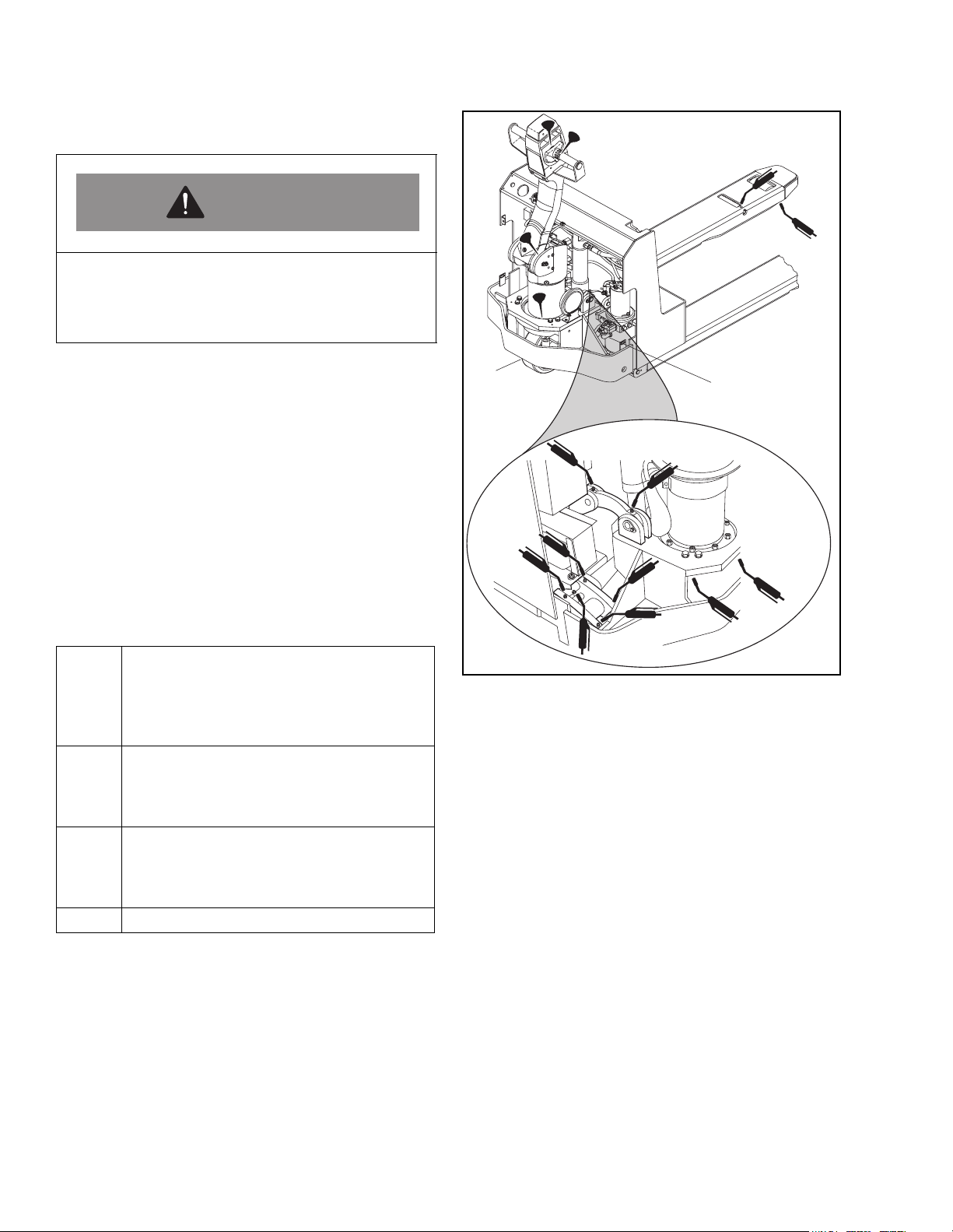
3-5. LUBRICATION
Refer to Table 3-3 for recommended types of grease
and oil. Table 3-3, in conjunction with Figure 3-1,
identifies the items requiring periodic lubrication and
where they are located on the lift truck.
Table 3-3. Recommended Lubricants
(See Table 3-4 for Application)
No. 1 Transmission oil - EP SAE 80W-go.
Capacity - 1.5 quart. Big Joe No. 055780
(Replace with 055790. 1W-30, if cold
conditioning option for continuous
operation below 320F is installed).
No. 2 Grease-Lithium base, general purpose. Big
Joe No. 055750 (Replace with 055753 if
cold conditioning option for continuous
operation below 320F is installed).
No. 3 Hydraulic oil. Big Joe No. 900855 (Gallon)
or 900893 (Quart). (Replace with 055784 if
cold conditioning option for continuous
operation below 320F is installed)
No. 4 Engine lubricating oil - No. 20
I-7044
Figure 3-1. Lubrication Locations
3-4 PPT0104-901336
Page 17
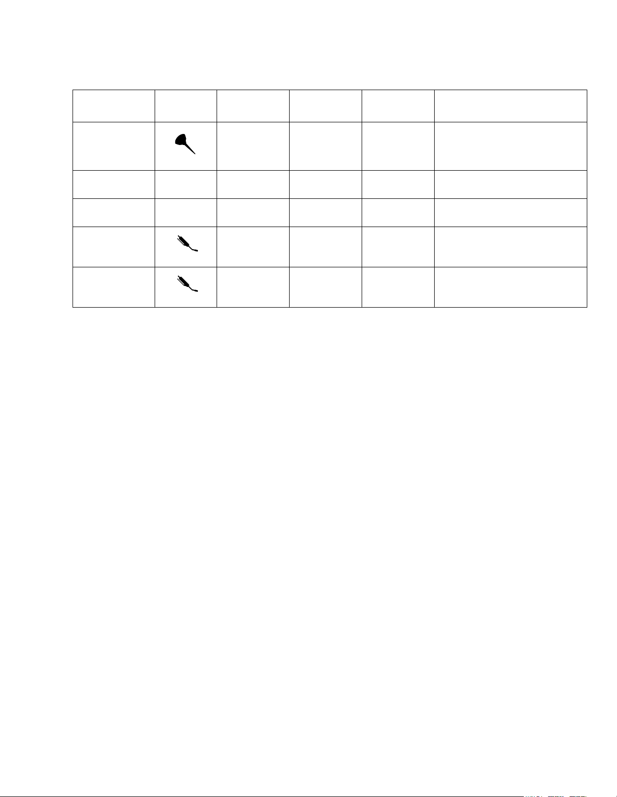
Table 3-4. Lubrication Chart
Time Interval
Semi-Annually
Annually
Semi-Annually
40 hours
Semi-Annually
*Raise lift truck to gain access to load wheels grease zerk. Illustration above shows only one side of the lift truck.
Repeat procedure on the other side of the truck.
Figure 3-1
Index
2
1
Location
Steering Arm
Elbow
Transmission
Housing
Hydraulic
Reservoir
Lift Linkage,
includes load
wheels*
Drive unit
turntable
bearings
Method Of
Application
Oil Can No. 4 1 or 2 drops each time serviced
Can No. 1 Fill to plug level
Can No. 3 Lower carriage, fill to 1 inch
Grease Gun No. 2 Pump until you see old grease
Grease Gun No. 2 5 or 6 pumps into each of two
Type
(Table 3-4)
Application of Lubricant
below elbow tap in reservoir
leave bushing
bearing grease fittings.
PPT0104-901336 3-5
Page 18

NOTES:
3-6 PPT0104-901336
Page 19
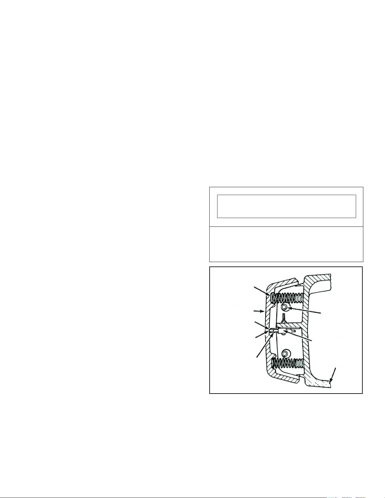
Section 4
ADJUSTMENT AND REPAIR
4-1. GENERAL
This section contains information and procedures for
maintenance of the PPT 45 lift trucks. Maintenance
includes adjustment, and repair.
The illustrations in this section identify lift truck
maintenance parts. The callouts on each illustration
correspond to the reference index numbers in the
applicable text.
Parts listings are provided in Section 7 of this manual.
The parts list provides the Big Joe Manufacturing
Company part number, the part description, and the
quantity of the part required in the assembly.
When identifying each part to be ordered, visually
compare the part in the illustration with the actual part
needed. To assure proper identification of each part
being ordered, include your truck model number and
serial number (see nameplate), the part number
description and quantity of the part(s) needed. If the
nameplate becomes lost or illegible, refer to Figure 1-1
for other serial number locations.
4-2. PART NUMBER IDENTIFICATION
To determine the part number of a replacement part,
identify the assembly in which the part is used and in
Section 7, locate the illustration of the appropriate
assembly. Find the index number for the part on the
illustration and refer to that index number in the parts
list. If the part number is NP, order the next higher
assembly. If the part number is VAR, order by part
name with truck model number and serial number
If the part is listed with more than one part number,
select the proper part number by comparing the
description in the parts list with the specifications of
your truck. Refer to the nameplate to determine
application to your truck.
4-3. STEERING ARM AND CONTROL HEAD
WARNING: Testing of belly-button safety switches in
operation should be limited to areas clear of obstacles
against which an operator could be pinned. Use low
speed in forward.
4-3.1 Belly-Button Switch Adjustment.
If the actuator gap of the belly-button switch needs
adjustment, proceed as follows (Figure 4-1):
1. Disconnect the battery.
2. Drive out the roll pins that secure the belly-button
casting (Figure 4-1). Drive from the left to the right.
NOTE: While removing the belly-button casting,
the two return springs will drop free. Catch
the springs while pulling the casting away
to prevent their loss.
3. Bend actuator levers of belly-button switches to
adjust the gap between rollers and belly-button
casting as required (See Figure 4-1).
IMPORTANT
If too small a gap exists between bellybutton switch
actuator rollers and the belly-button casting, one or
both of the belly-button switches may be actuated
constantly.
Belly Button
Springs
Belly Button
Casting
Gap
Roller
Bend Actuator
Levers Here
Figure 4-1. Steering Arm Control Head
Roll Pins
Belly Button
Switches
Control
Head
I-7006
PPT0104-901336 4-1
Page 20

4. Reinstall belly-button casting, making certain all
parts are back in place. Check operation of the
belly-button safety switches by pressing the bellybutton casting while listening for the 'click' that
indicates that the switches have actuated.
4. Disconnect the connector round located at
contactor panel, connecting the control cable and
wire harness. Set an ohmmeter to the RXIK (1000)
scale and connect across pin contacts of wires 7
and 11 at the control cable pin housing.
NOTE: The click should be heard when the belly-
button casting has moved about 50
percent of its normal travel distance. If the
click is heard at the beginning of travel, the
switches may actuate at inappropriate
times. If the click is heard near the end of
travel, they should be adjusted to activate
earlier.
5. Repeat steps 2 through 4 until pressing the
bellybutton casting actuates the switches properly
6. Reconnect battery and turn power ON with
keyswitch. In an open, unrestricted area and
traveling at a low speed in forward (towards
operator), press the belly-button casting inwards to
confirm that the belly-button switches reverse the
truck direction.
4-3.2 Potentiometer Testing and Adjustment
1. Disconnect the battery
2. Remove screws (20 and 64, Figure 4-2) and
access covers (40 and 66).
3. Check gap between rollers on directional switches
(7) and surface of cam (46). If required, adjust
position of bracket (50) to obtain a 0.03-0.06 inch
clearance.
5. Slowly press the control lever (52, Figure 4-2) in
the forward direction until a click indicating forward
switch closure is heard. Ohmmeter should indicate
4550 ohms (± 250 ohms).
6. If incorrect reading is obtained, use access hole, in
the side of the control head (Figure 4-3) to gain
access to the potentiometer. (3, Figure 4-2). Insert
a screwdriver blade into the slot on the back side of
the potentiometer (Figure 4-3) and turn slightly.
Vary the amount and direction of screwdriver
rotation until the specified value is achieved.
7. Repeat step 5 while pressing control lever in
reverse direction. Meter readings should be the
same as for the forward direction (± 200 ohms). If
meter readings are not the same, adjust position of
bracket (44, Figure 4-2) as necessary to obtain the
same values. Adjust the potentiometer again if
necessary.
8. Reassemble the control head.
4-2 PPT0104-901336
Page 21
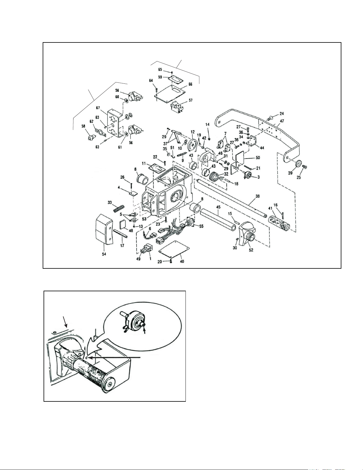
Push Button
Switch
Assembly
High Speed
Cutout Switch
Assembly
Figure 4-2. Control Head Assembly
Control
Head
Potentiometer
Adjustment Slot
Adjustment
Access Hole
I-7008
Figure 4-3. Control Head Potentiometer Adjustment
I-7007
4-3.3 Control Head Switch Replacement
1. Disconnect the battery.
NOTE: Access to belly-button switches (5, Figure
4-2) is provided by removal of safety cover
(54). Access to other switches is provided
by removal of top cover (66), bottom cover
(40), and switch plate (67).
2. Refer to Section 4-3.1, if necessary to gain access
to a defective belly-button switch.
NOTE: Switch operation may be checked with a
continuity light containing a battery, or with
an ohmmeter.
3. Replace a defective belly-button switch (5) as
follows:
a. Remove locknuts (13) and screw (26) to
release belly-button switch (5) and insulator
(4).
PPT0104-901336 4-3
Page 22
b. Tag and disconnect electrical wires from
bellybutton switchs.
c. Connect electrical wires to new belly-button
switchs, as noted during removal.
d. Install insulator (4) and belly-button switch (5)
and secure with screws (26) and locknuts (13).
e. Adjust belly-button switch (Section 4-3.1).
4. Replace a defective high speed cutout switch (57)
as follows:
a. Disconnect the battery.
b. Remove screws (64) and top cover (66).
c. Remove screws (65) to release cutout switch
(57).
d. Tag and disconnect electrical wires from the
old cutout switch (57).
e. Connect electrical wires to new cutout switch
(57) to the same terminals from which they
were removed.
f. Install cutout switch (57) into the control head
and secure with screws (65).
g. Install control head top cover (66) and secure
with screws (64).
h. Connect battery.
5. Replace a defective pushbutton switch (56 or 58)
as follows:
a. Disconnect the battery.
b. Remove screws (64) and top cover (66).
c. Remove screws (20) and bottom cover (40).
d. Remove screws (22 and 23) to release switch
plate (67).
e. Remove screws (63) to remove lift or lower
switch (56).
f. Remove nut and washer (61) from back of
horn switch (58) to remove it from the switch
plate (67).
g. Tag and disconnect electrical wires from
defective switch.
h. Connect wires to new switch, as noted during
removal.
i. To install lift or lower switch (56), slide the new
switch through back of switch plate (67) and
secure with screws (63).
j. To install horn switch (58), slide the switch
through the front of switch plate (67) and
secure with its washer and nut.
k. Install switch plate (67) and secure with screws
(22 and 23).
l. Install top cover (66) and secure with screws
(64).
m. Install bottom cover (40) and secure with
screws (20).
n. Connect the battery.
4-3.4 Steering Arm.
1. Steering Arm Return Spring Adjustment (Figure 4-
4)
WARNING
The steering arm will fall when the tension on the
return spring is released.
The tension on the steering arm return spring
should allow the steering arm to return gently to the
upright position. Excessive tension on the steering
arm return spring will cause the steering arm to
snap up and may cause damage to the electrical
cable or to the spring.
If the steering arm does not fully return, first check
for binding in the wiring harness before making any
adjustments. If no binding is found, then the problem is with the steering arm return spring. Refer to
Figure 4-4 and proceed as follows to adjust the
steering arm return spring tension.
a. Hold the steering arm (2, Figure 4-4) in the
upright position and make sure the arm
cannot fall.
b. Insert a 5/16 inch Allen wrench through hole in
bottom of steering arm (2) and loosen screw
(20). The spring tube (25) will rotate
counterclockwise when screw (20) is loosened.
c. With a pair of vise-grip pliers, grip the flat
surfaces of spring tube (25) and rotate
clockwise 180 degrees.
NOTE: The flat surfaces are on the protruding
end of the spring tube (25), where the
pins (15 and 16) are installed.
d. Hold spring tube (25) in rotated position and
tighten screw (20) to secure.
e. Check the spring action by lowering the
steering arm (2) and returning it to the upright
position two or three times.
f. If necessary repeat steps a through e,
increasing or decreasing amount of rotation of
the spring tube (25) until steering arm (2)
returns gently to full upright position.
4-4 PPT0104-901336
Page 23
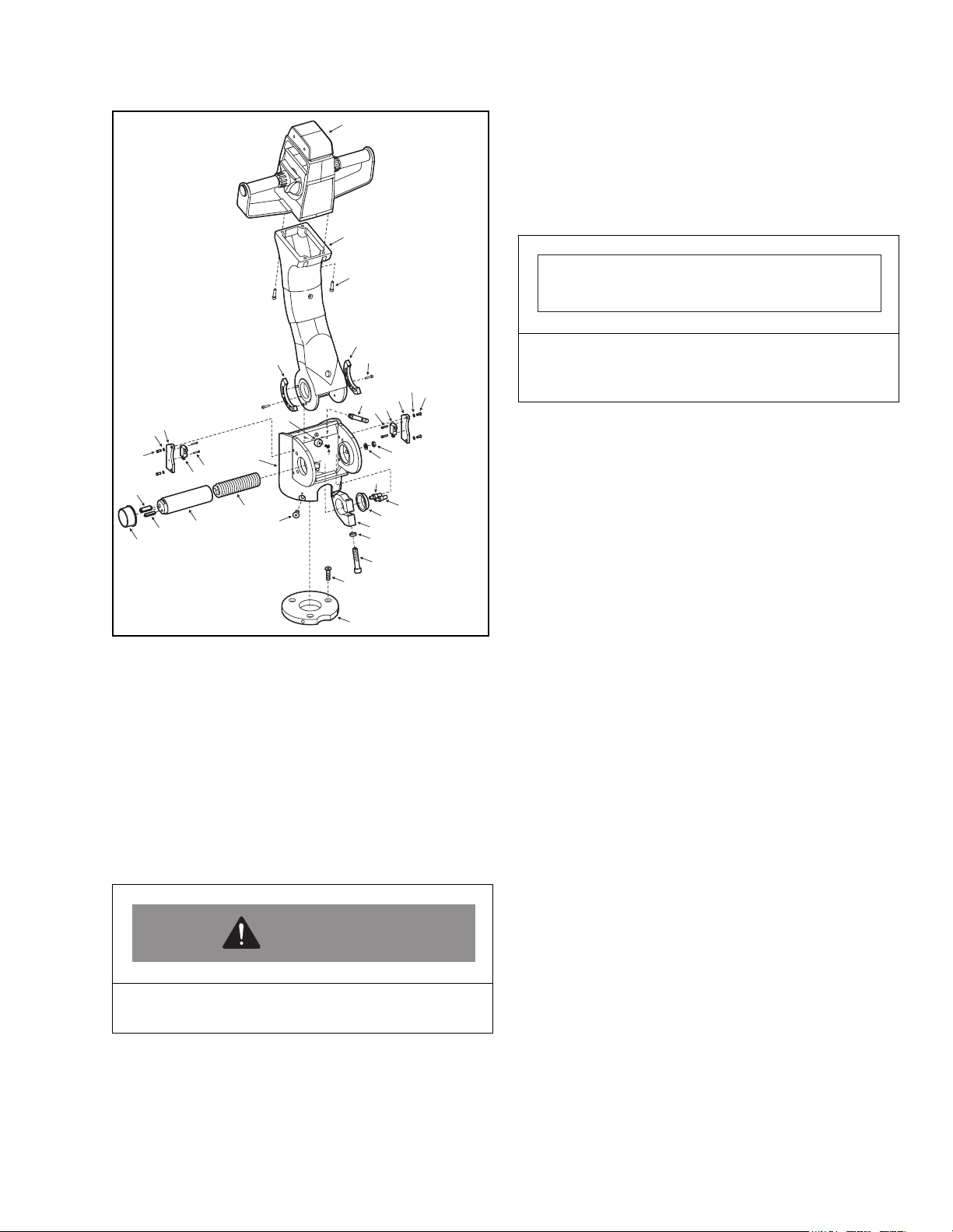
1
alignment match mark to assist in reinstallation.
e. Insert a 5/16 inch Allen wrench through hole in
bottom of steering arm (25, Figure 4-4).
Loosen and remove screw (20) and spacer
(19).
2
3
4
31
10
11
12
28
27
8
9
25
26
29
32
24
23
5
11
12
10
7
9
8
30
21
13
14
15
16
17
18
19
20
22
I-7057
Figure 4-4. Steering Arm Spring
4-3.5 Steering Arm Spring Replacement
The steering arm return spring (24, Figure 4-4) is
replaced while the steering arm (2) is in the upright
position.
a. Disconnect battery.
b. Remove control head by removing the four
capscrews (3). Remove the control from the
control arm and disconnect the round control
cable connector.
WARNING
The steering arm will fall downward when the
tension on the return spring is released.
c. Hold steering arm (2) and make sure the arm
cannot fall.
d. With a piece of chalk or crayon, draw a straight
line from center of spring tube (11, Figure 4-4)
outward onto steering tube, marking an
IMPORTANT
Unless properly supported, steering arm (2) will drop
out of the steering tube when the spring tube (25,
Figure 4-4) is removed.
f. Put a block under steering arm (2) at steering
tube.
g. With a pair of vise-grip pliers, grip the flat
surfaces of spring tube (25, Figure 4-4) and
slowly pull it free from the steering arm (2),
steering tube and tube clamp (18, Figure 4-4).
NOTE: The flat surfaces are on the protruding
end of the spring tube (25), where the
pins (15 and 16) are installed. Steering
arm return spring (24) will remain
inside the spring tube (25).
h. Remove steering arm return spring (24) from
spring tube (25). If spring is severely jammed
and will not come loose, use punch and drive
the 1/4-inch diameter roll pin (26) into the tube.
Save pin for re-use. Remove the spring. Tap
roll pin back into place.
i. Lubricate the ends and the outer surface of the
new steering arm return spring (24) with a
lithium base general purpose grease.
j. Insert spring (24) into spring tube (25) and
press in, making sure that one spring loop eye
fits over the 3/8-inch pin (28) at the closed end
of the spring tube.
k. Slide spring tube (25) into pivot cap and
steering arm (2) through tube clamp (18).
Slowly rotate spring tube a few degrees each
way until the steering arm return spring (24)
snaps into place over spring pin (15).
l. Install spacer (19) and screw (20), but do not
tighten. Align match mark on the spring tube
(25) with the line drawn in step e. Tighten
screw (20).
m. Remove block from under steering arm.
n. Install control head.
PPT0104-901336 4-5
Page 24
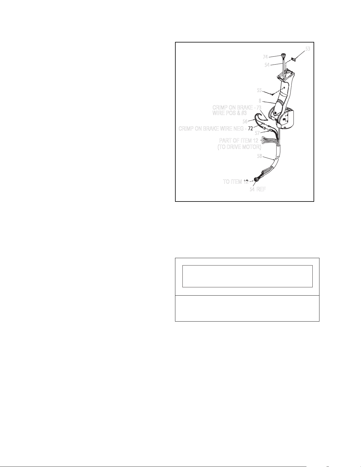
o. Refer to paragraph 4-3.4, step 1, above, and, if
53
8
55
58
57
56
CRIMP ON BRAKE WIRE NEG
73
CRIMP ON BRAKE
WIRE POS & #3
PART OF ITEM 12
(TO DRIVE MOTOR)
TO ITEM 12
54
54
necessary, adjust the tension on steering arm
return spring.
p. Reconnect battery.
4-3.6 Electrical Control Cable Replacement.
1. Disconnect battery.
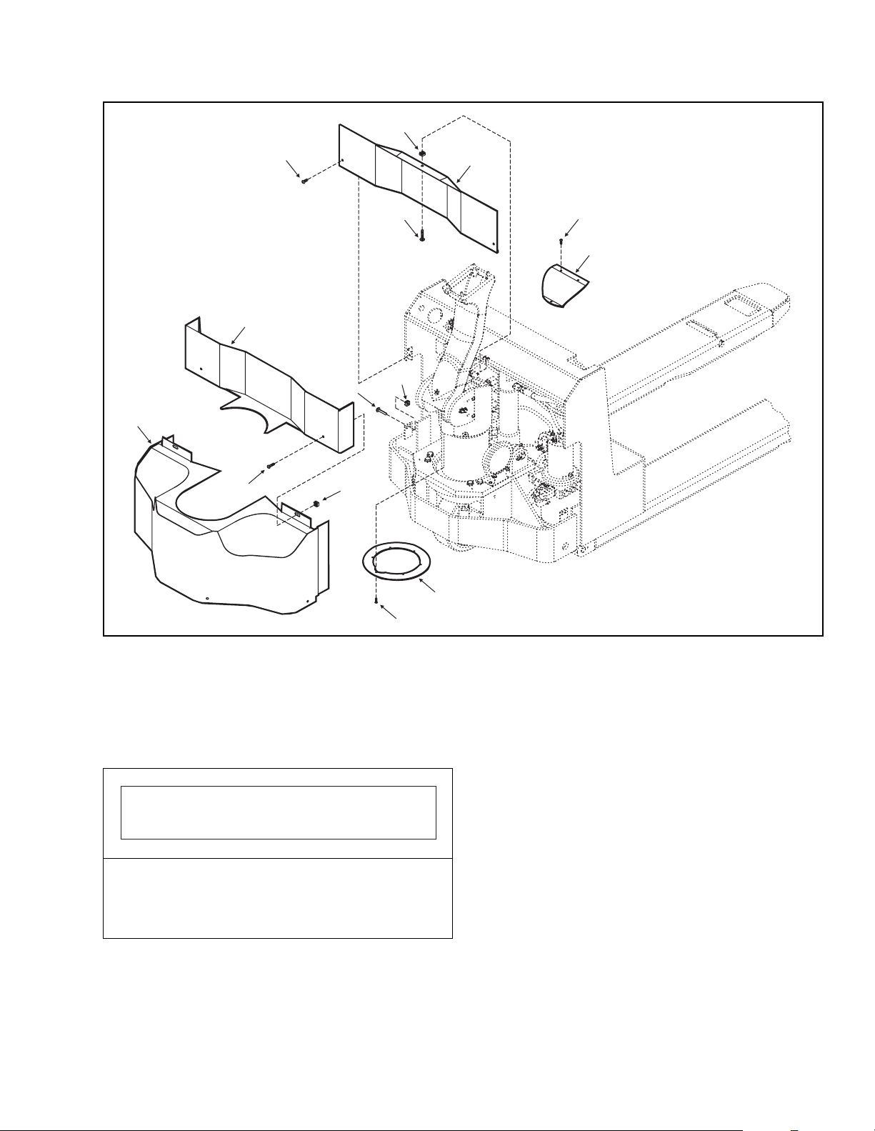
2. Remove screws (66, 67 and 68, Figure 4-6), lockwashers, flat washers, and motor compartment
covers (61, 62 and 69). Remove the three brake
cover plate screws (46) and the brake cover plate
(64).
3. Remove 4 screws (23, Figure 4-4) that fasten
control head assembly to steering arm.
4. Disconnect the exposed control cable connector
(74, Figure 4-5).
5. Remove cable clamp (53) located within the control
arm by loosening screw (55).
6. Disconnect connector (54) located inside the motor
compartment, above the top end of the hydraulic
cylinder.
7. Cut off connector (74) from the top end of the
cable.
NOTE: Measure the amount of excess cable that
is located at the top end of the control arm.
Make sure to leave this additional amount
of new cable.
Tape the loose end of the new cable to the
cut end of the old cable before removing
the old cable from the control arm.
8. Pull the cut end of cable out of the control arm from
below. Make sure to pull the new cable through
until the new connector has just enough slack to
enable connection to the control head.
9. Remove the four screws (1, Figure 4-6) from the
ring guard (3) and slide the guard upwards.
10. Remove the two cable clamps to free drive motor
and control cable bundle. Note routing of cable,
and position of cable clamps, to ensure proper
installation.
I-7010
Figure 4-5. Control wiring Harness
11. Cut the electrical tape at both ends of the braided
fabric sleeve that is bundling the cables and slide
the sleeve towards one end. This will release the
pressure on the sleeve making cable removal
easier.
IMPORTANT
Take care not to cut or damage the four red brake
controls wires that are bundled with the control
cable.
12. Pull the old control cable out of the bundle and
remove the cable from the lift truck.
13. Using electrical tape, wrap the loose ends of the
new cable together.
14. With the braided fabric sleeve in the relaxed
condition, thread the new cable through the
braided sleeve. Make sure to leave enough cable
at each end of the braided sleeve to enable
connections to be made properly.
4-6 PPT0104-901336
15. Group all cables coming from drive motor, deadman switch and control cable, and reinstall cable
clamp (5, Figure 4-5). Make sure to remove excess
slack from the new cable assembly before securing
with cable clamp.
Page 25
4
9
68
7
66
10
1
46
2
64
8
62
65
7
4
66
6
69
67
5
65
4
46
3
1
Figure 4-6. Motor Compartment Service Covers
16. Secure one end of the braided fabric sleeve to the
cable bundle with electrical tape. Pull the fabric
sleeve taught and securely tape the remaining end
of the fabric sleeve to the cable bundle with
electrical tape.
IMPORTANT
Improper cable adjustment will damage cable. If too
tight, cable will tear when steering arm is in up
position. If too loose, cable will buckle or be pinched
when steering arm is in down position.
17. Work steering arm up and down a few times to
assure that the electrical control cable is not
binding.
63
I-7059
18. Pivot transmission through entire turning range,
make sure that all electrical cables and wire leads
will flex properly and not become caught or
pinched at any time.
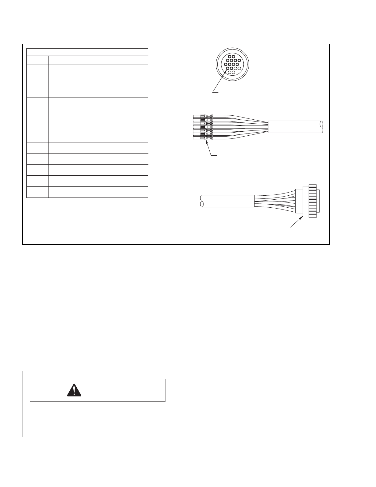
19. Reinstall wires 1 through 12 into pin locations 1
through 12, respectively in the new connector. See
Figure 4-7.
20. Reattach the round control cable connector (54,
Figure 4-5) within the motor compartment.
21. Reinstall the control head assembly, attaching the
round connector to the end of the new control
harness (74, Figure 4-5) and secure with screws
(3, Figure 4-4).
22. Install brake tube cover plate (2, Figure 4-6).
23. Install motor compartment covers (6, 8 and 10,
Figure 4-6) and secure with flat washers,
lockwashers and screws.
24. Connect the battery and test operate the lift truck.
PPT0104-901336 4-7
Page 26
HOUSINGS
PIN NO.
1
WIRE NO.
1
004705 CABLE
WIRE COLOR
BLACK
2
3
4
5
6
7
8
9
10
11
10
11
12 12
2
3
RED
BLUE
CONTACT-SOCKET
SEE CHART FOR
4
5
6
7
8
ORANGE
YELLOW
BROWN
RED W/BLACK STRIPE
BLUE W/BLACK STRIPE
PIN CONNECTIONS
1
2
3
4
5
6
7
LOOSE SOCKET WIRES -
9
ORANGE W/BLACK STRIPE
YELLOW W/BLACK STRIPE
CONNECT ACCORDING
TO CHART
BROWN W/BLACK STRIPE
BLACK W/RED STRIPE
CONNECTOR
I-7019
Figure 4-7. Control Cable Connections
4-4. BRAKES
4-4.1 Brake Pad Adjustment
1. Disconnect battery.
2. Jack up the truck so the drive wheel is off the
ground; then securely block the truck to prevent
movement.
3. Remove screws (5, 7 and 9, Figure 4-6), lockwashers, flat washers, upper and lower motor
compartment covers (6, 8 and 10).
4. Remove the four screws (1) securing the guard
ring (3) and slide the guard ring upwards as much
as possible.
CAUTION
Removing the mounting screws will loosen the
steering arm. Support the arm to prevent injury
from falling steering arm.
5. Remove the four screws (23, Figure 4-4) securing
the steering arm to the drive motor assembly and
remove the steering arm, providing access to the
brake assembly.
NOTE: Use caution when removing the steering
arm that brake and control head cables
are not disconnected or damaged.
6. Locate the rubber seal on the brake assembly (1,
Figure 4-8) Slide the rubber cover seal upwards
onto the armature to enable access to the
adjustment points (2).
4-8 PPT0104-901336
Page 27
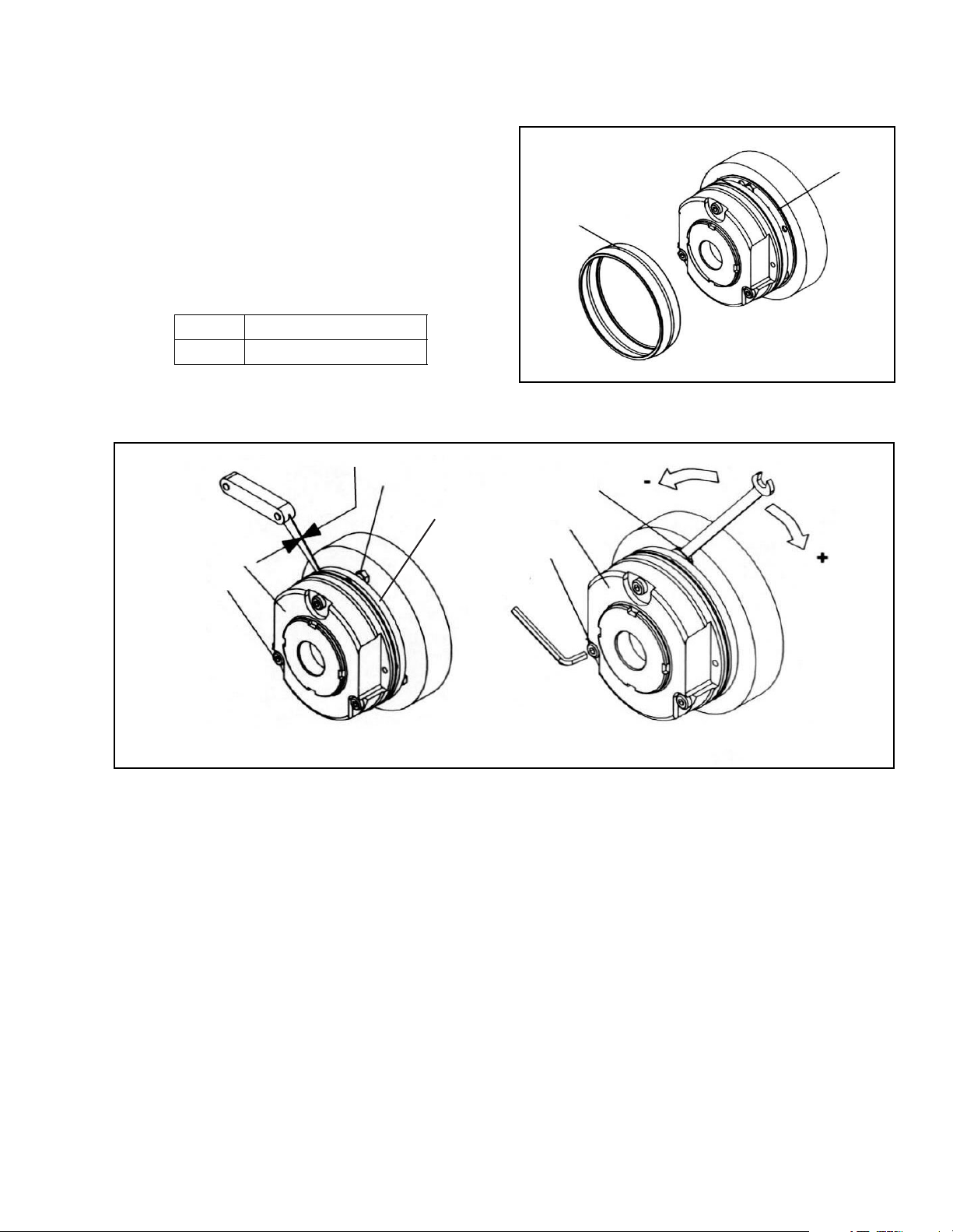
7. Adjust the air gap between the armature plate (2,
Figure 4-9) and the stator (1) using the three
hexagon screws (3). Using standard feeler gauges,
adjust to achieve the dimension "SLU" at each hex
nut, which sets the gap for the armature plate
(Table 4-1). When the adjustment has been made
at each hex nut, recheck all other hex nuts to verify
the adjustment.
Table 4-1. Brake Pad Air
Gap Adjustment Measurement
Size 16
SLU 0.012" (0.3 mm)
S
LU
3
2
2
1
I-7014
Figure 4-8. Electric Brake Assembly
3
1
1
4
Figure 4-9. Brake Pad Adjustment
8. Reinstall the rubber cover seal (1, Figure 4-8).
Make sure to seat the seal around the base of the
armature plate and the lower groove in the
armature.
9. Reinstall the steering arm.
10. Remove blocking and lower truck
11. Reconnect the battery and test the brake function.
12. Repeat brake adjustment as needed to make sure
that the stops properly.
4
I-7014
4-4.2 Brake Pad Replacement
Replace the brake if it does not engage when the
steering arm is raised to within 15 degrees from its park
position or lowered to within 15 degrees from its lowest
position (Figure 2-2) and brake pad adjustment does
not improve braking. Proceed as follows:
1. Disconnect battery.
2. Jack up the truck so the drive wheel is off the
ground; then securely block the truck to prevent
movement.
3. Remove screws (5, 7 and 9, Figure 4-6), lockwashers, flat washers, upper and lower motor
compartment covers (6, 8 and 10).
PPT0104-901336 4-9
Page 28
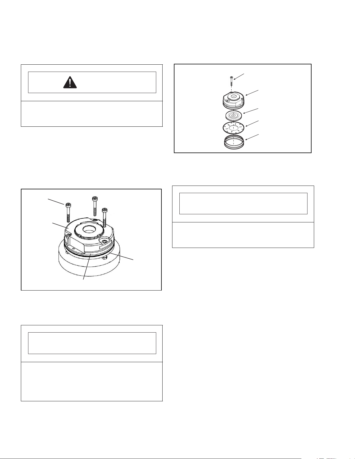
4. Remove the four screws (1) securing the guard
ring (3) and slide the guard ring upwards as much
as possible.
9. Remove and replace the friction plate (4) and
brake hub (3) assemblies.
1
CAUTION
Removing the mounting screws will loosen the
steering arm. Support the arm to prevent injury
from falling steering arm.
5. Remove the four screws (23, Figure 4-4) securing
the steering arm to the drive motor assembly.
NOTE: Use caution when removing the steering
arm that brake and control head cables
are not disconnected or damaged.
6. Remove the three brake assembly mounting bolts
(1, Figure 4-10).
1
2
2
3
4
5
I-7036
Figure 4-11. Brake Parts
10. Align the friction plate mounting holes with the
mounting bolt holes.
IMPORTANT
Make sure that the raised edge of the friction plate
(4) is facing upwards toward the brake hub
assembly.
3
4
Figure 4-10. Brake Assembly
7. Lift the brake assembly (2) off of the drive motor
assembly.
I-7015
IMPORTANT
The splined hub on the brake hub (3, Figure 4-11)
assembly must be positioned downwards, towards
the center of the motor assembly. If the brake hub is
not assembled in this fashion, damage to the splined
gear may result.
8. Slide the rubber cover seal (5, Figure 4-11)
upwards, loosening the friction plate (4) and brake
hub (3) assembly.
11. Insert the three mounting bolts (1, Figure 4-11)
through the brake assembly and reposition over
the splined shaft on the drive motor assembly.
12. Secure the three brake assembly mounting bolts
(1). Torque the bolts to 17 ft. lbs. (23 Nm).
13. Adjust the brake air gap. See Section 4-4.1 Brake
Pad Adjustment.
14. Slide the rubber cover seal into place.
15. Reinstall the steering arm assembly. Secure the 4
mounting bolts (23, Figure 4-4).
NOTE: Make sure to route the electric wires and
cable through the semi-circular notch in
the brake assembly mounting plate on top
of the drive motor assembly.
16. Reposition the guard ring (3, Figure 4-6) and
secure with the four mounting screws (1).
17. Reinstall motor compartment covers (6, 8 and 10).
18. Remove blocking and lower truck
19. Reconnect the battery.
4-10 PPT0104-901336
Page 29
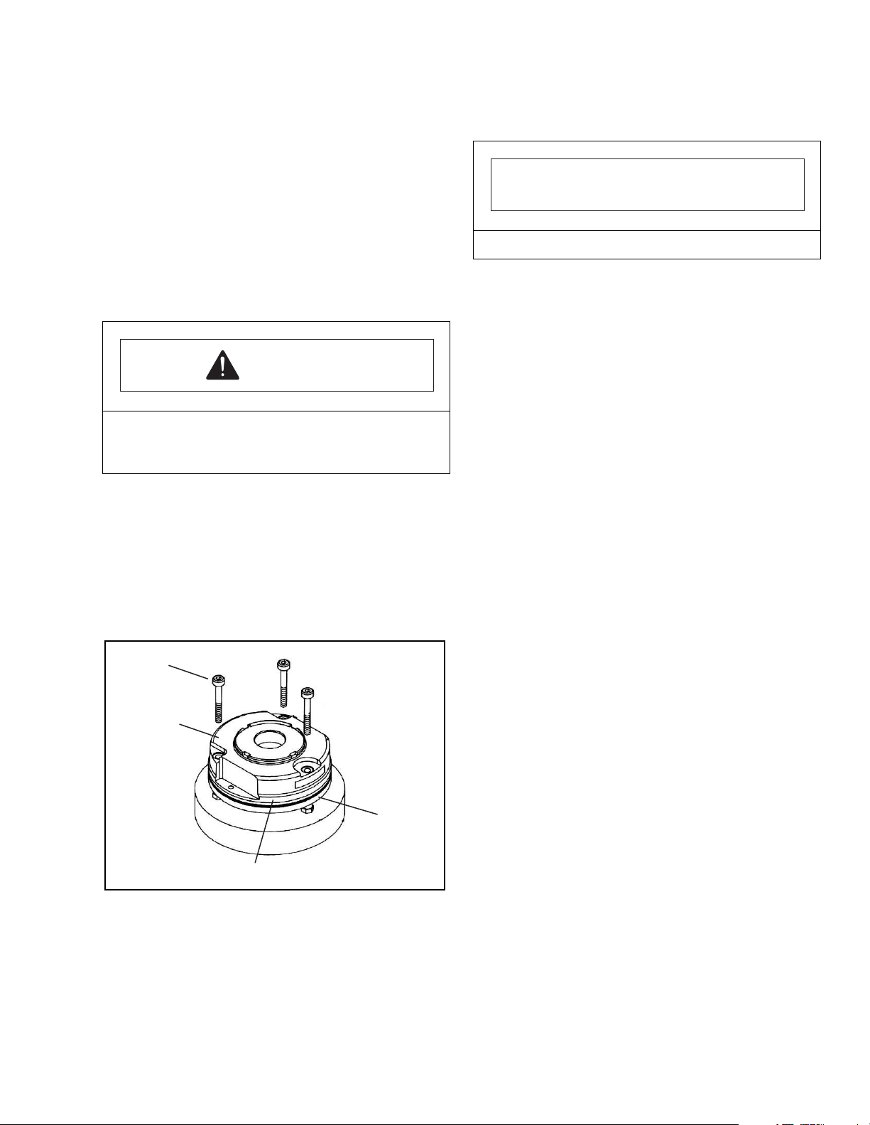
4-4.3 Replacement of Brake Assembly
1. Disconnect battery.
2. Jack up the truck so the drive wheel is off the
ground; then securely block the truck to prevent
movement.
3. Remove screws (5, 7 and 9, Figure 4-6), lockwashers, flat washers, upper and lower motor
compartment covers (6, 8 and 10).
7. Trace the wire harness to the Creep and Deadman
switches.
IMPORTANT
Note connections before removing wires.
4. Remove the four screws (1) securing the guard
ring (3) and slide the guard ring upwards as much
as possible.
CAUTION
Removing the mounting screws will loosen the
steering arm. Support the arm to prevent injury
from falling steering arm.
5. Remove the four screws (23, Figure 4-4) securing
the steering arm to the drive motor assembly.
NOTE: Use caution when removing the steering
arm that brake and control head cables
are not disconnected or damaged.
6. Remove the three brake assembly mounting bolts
(1, Figure 4-12).
1
2
Remove the wires from the two switches and disconnect the three wire connector.
8. Cut the red and blue wires as close to the crimp-on
connector as possible.
NOTE: A new crimp-on connector is included with
the replacement brake assembly.
9. Remove the old brake assembly (2, Figure 4-12).
10. Install new brake assembly and secure with the
three cap screws (1, Figure 4-12).
11. Using the provided crimp-on connector connect the
red and blue wires to the wiring harness.
12. Adjust the brake air gap. See Section 4-4.1 Brake
Pad Adjustment.
13. Reinstall the steering arm assembly. Secure the 4
mounting bolts (23, Figure 4-4).
NOTE: Make sure to route the electric control
cable through the semi-circular notch in
the brake assembly mounting plate on top
of the drive motor assembly.
14. Reposition the guard ring (63) and secure with the
four mounting screws (3, Figure 4-6).
15. Reinstall motor compartment covers (6, 8 and 10).
16. Remove blocking and lower truck
17. Reconnect the battery.
3
4
Figure 4-12. Brake Parts
PPT0104-901336 4-11
I-7015
Page 30
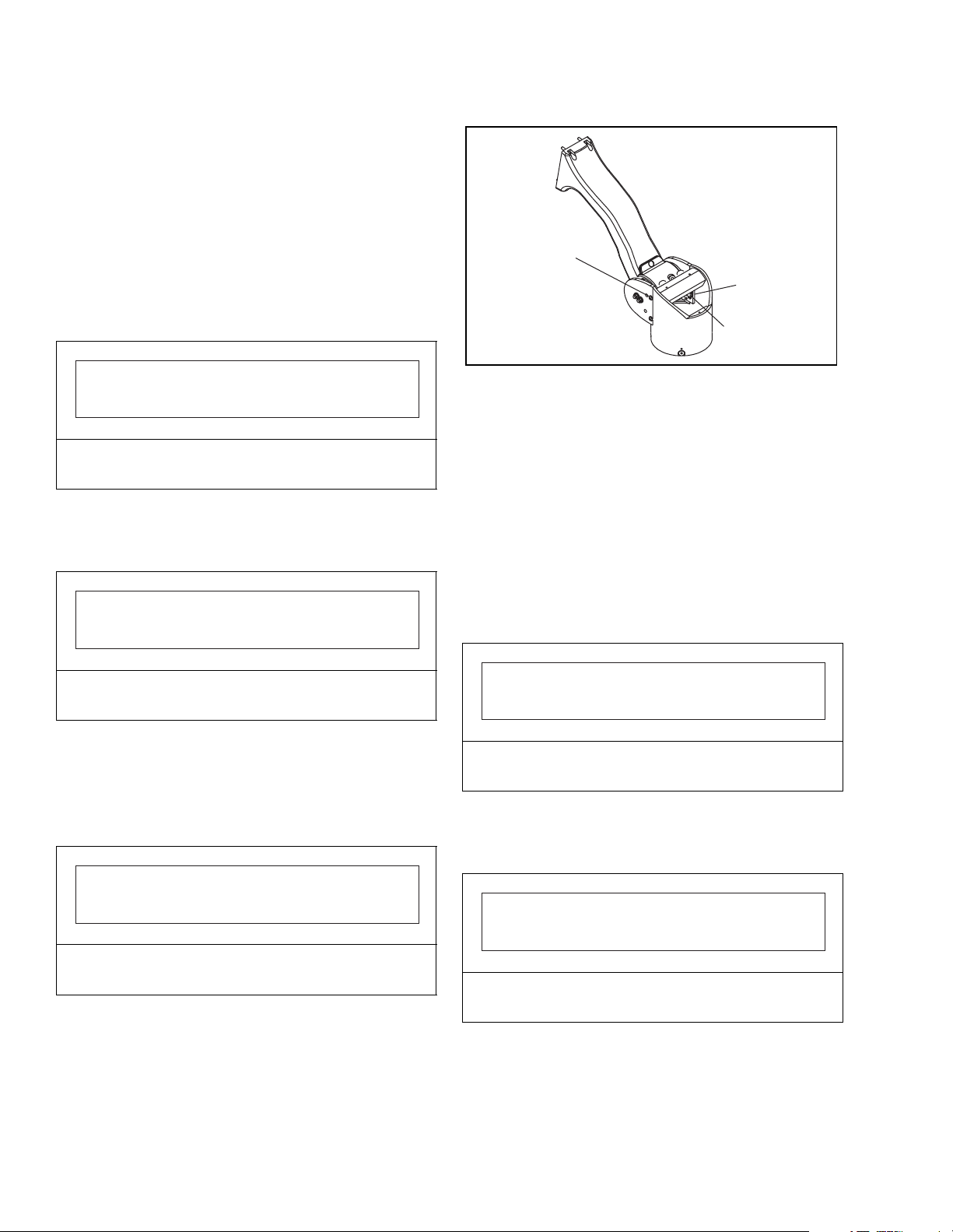
4-4.4 Replacement of Dead-Man Switch
1. Disconnect the battery.
2. Block the wheels to prevent the truck from rolling.
3. Remove the steering tube cover plate (2, Figure 4-
6).
4. Remove the switch mounting bracket mounting
screws (3, Figure 4-13).
NOTE: When standing at the control head, the
Dead Man Switch is located on the right
hand side of the steering tube.
3
2
1
I-7016
IMPORTANT
DO NOT loosen the mounting screws for the dead-
man actuation cams.
5. Remove the switch mounting bracket (2) and
switch assembly (1).
6. Note the wire connections to the switch.
IMPORTANT
Make sure to note the terminals to which the wires
are connected.
7. Remove the switch (1) from the mounting bracket
(2) and install new switch onto mounting bracket.
8. Reconnect wiring to match the original switch.
9. Reinstall switch mounting bracket onto steering
tube.
Figure 4-13. Dead Man Switch
4-4.5 Replacement of Creep Travel Switch
1. Disconnect the battery.
2. Block the wheels to prevent the truck from rolling.
3. Remove the steering tube cover plate (2, Figure 4-
6).
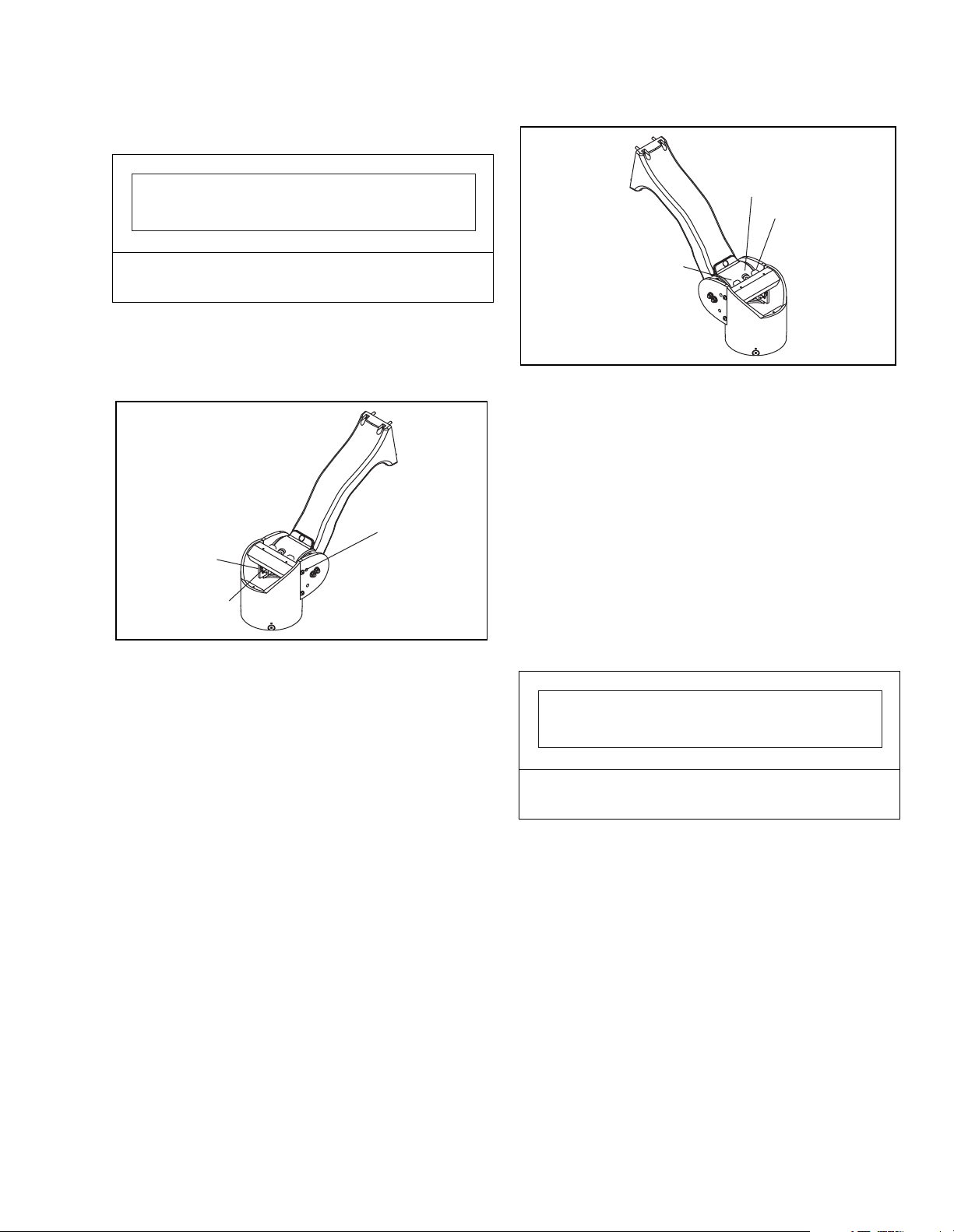
4. Remove screws (3, Figure 4-14) securing the
dead-man switch mounting bracket.
NOTE: When standing at the control head, the
Creep Travel Switch is located on the left
hand side of the steering tube.
IMPORTANT
DO NOT loosen the mounting screws for the creep
travel actuation cams.
5. Remove the switch mounting bracket (2) and
switch assembly (1).
6. Note the wire connections to the switch.
IMPORTANT
IMPORTANT
Make sure not to pinch any of the wires when
reinstalling the mounting bracket.
10. Reinstall steering tube cover plate.
11. Reconnect battery, remove wheel blocking and test
operate truck to verify dead-man switch operation.
4-12 PPT0104-901336
Make sure to note the terminals to which the wires
are connected.
7. Remove the switch (1) from the mounting bracket
(2) and install new switch onto mounting bracket.
8. Reconnect wiring to match the original switch.
Page 31
9. Reinstall switch mounting bracket onto steering
tube.
IMPORTANT
1
2
Make sure not to pinch any of the wires when
reinstalling the mounting bracket.
10. Reinstall steering tube cover plate.
11. Reconnect battery, remove wheel blocking and test
operate truck to verify dead-man switch operation.
3
2
1
I-7017
Figure 4-14 . Creep Travel Switch
4-4.6 Replacement of Control Arm Shock
Absorber
If the control arm snaps upwards when it is released
and the arm impacts the two rubber stops (2, Figure 4-
15), observe the operation of the control arm shock
absorber (1). The shock absorber should contact the
control arm before the arm contacts the rubber
bumpers, slowing the upward travel speed. If the shock
absorber does not function in this way, it needs to be
replaced.
1. Hold control arm in a lowered position.
2. Remove the old shock absorber (1).
3. Install new shock absorber.
4. Hold the control arm in the operating position and
release. The shock absorber should slow the
upward travel of the control arm.
2
I-7018_1
Figure 4-15. Control Arm Shock Absorber
4-5. DRIVE MOTOR, TRANSMISSION, DRIVE
WHEEL, AND PIVOT TUBE ASSEMBLY
4-5.1 Drive Motor Servicing.
The drive motor exposed surfaces should be cleaned
at least once a month to assure proper cooling of
motor. Use an air hose to blow bust off of motor
surfaces.
If the truck does not run and the drive motor is at fault,
disconnect the battery and inspect brushes (2, Figure
4-17) and commutator (on armature). Replace brushes
if they are worn. Remove rough spots on the
commutator with fine sandpaper.
IMPORTANT
Make sure to remove any sandpaper particles or
dust from the commutator before reassembly.
4-5.2 Inspect and replace worn brushes as
follows:
1. Disconnect the battery.
2. Make sure the four cables to the drive motor are
properly labeled Al, A2, Fl, and F2; then disconnect
the cables from the drive motor.
3. Move the power and control cable bundle out of the
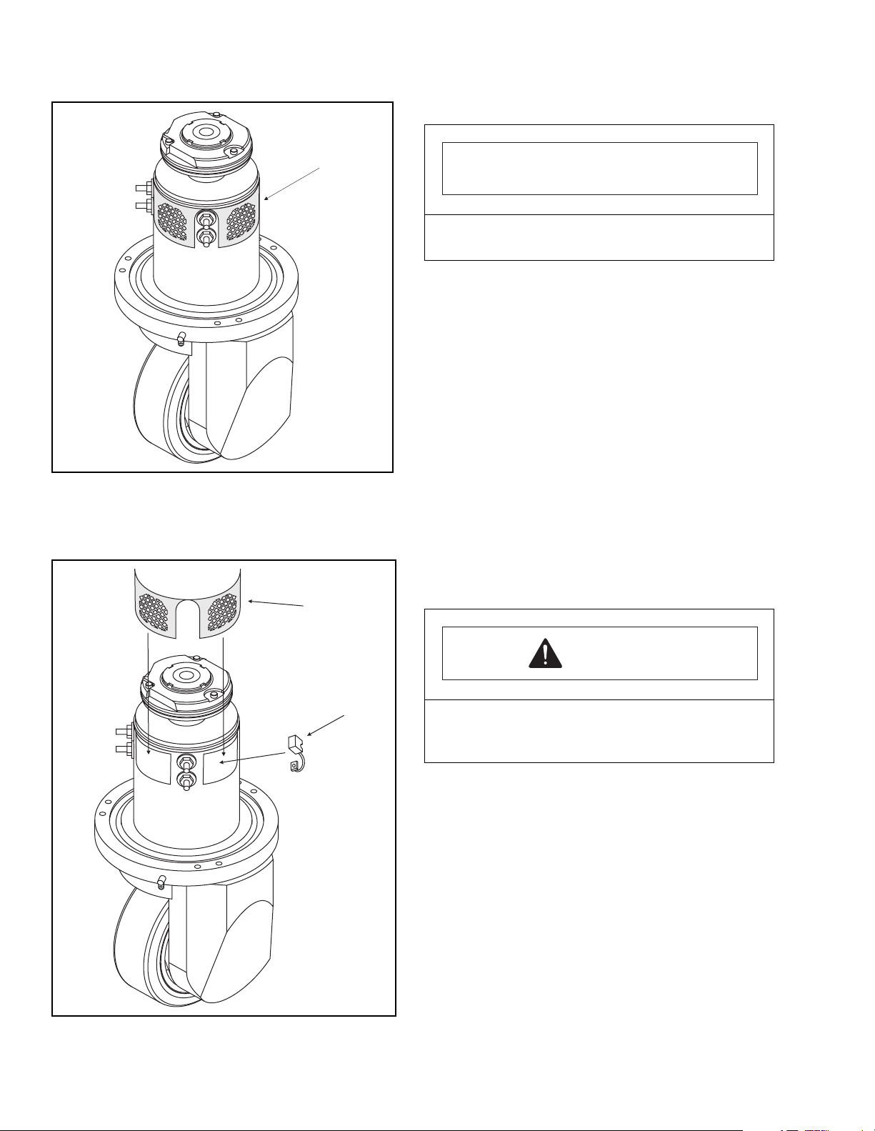
way. Loosen and remove the motor headband (1,
Figure 4-16).
PPT0104-901336 4-13
Page 32
1
I-7020
Figure 4-16. Remove Motor Headband
4. Loosen the mounting screw on each brush power
lead and remove brush.
1
IMPORTANT
Make sure that the brush spring is not removed from
the support pin or allowed to unwind.
5. Install new brush, reseat brush spring and secure
the electrical lead.
6. Repeat Steps 3 and 4 for remaining brushes.
4-5.3 Inspect commutator assembly.
If the brushes are not worn and the motor does not run,
inspect the commutator for wear or damage as follows:
1. Disconnect the battery.
2. Jack up the truck so the drive wheel is off the
ground; then securely block the truck to prevent
movement.
3. Remove screws (5, 7 and 9, Figure 4-6), lockwashers, flat washers, upper and lower motor
compartment covers (6, 8 and 10).
4. Remove the four screws (1) securing the guard
ring (3) and slide the guard ring upwards as much
as possible.
Figure 4-17. Replace Motor Brushes
2
I-7021
CAUTION
Removing the mounting screws will loosen the
steering arm. Support the arm to prevent injury
from falling steering arm.
5. Remove the four screws (23, Figure 4-4) securing
the steering arm to the drive motor assembly.
NOTE: Use caution when removing the steering
arm that brake and control head cables
are not disconnected or damaged.
6. Remove spring clip, splined gear and woodruff key
(1, 2 and 3, Figure 4-18).
7. Remove allen head screws (4) and motor end plate
(5).
8. Remove headband assembly (1, Figure 4-16).
9. Remove commutator end-head assembly (7,
Figure 4-18) and upper bearing (9).
4-14 PPT0104-901336
Page 33
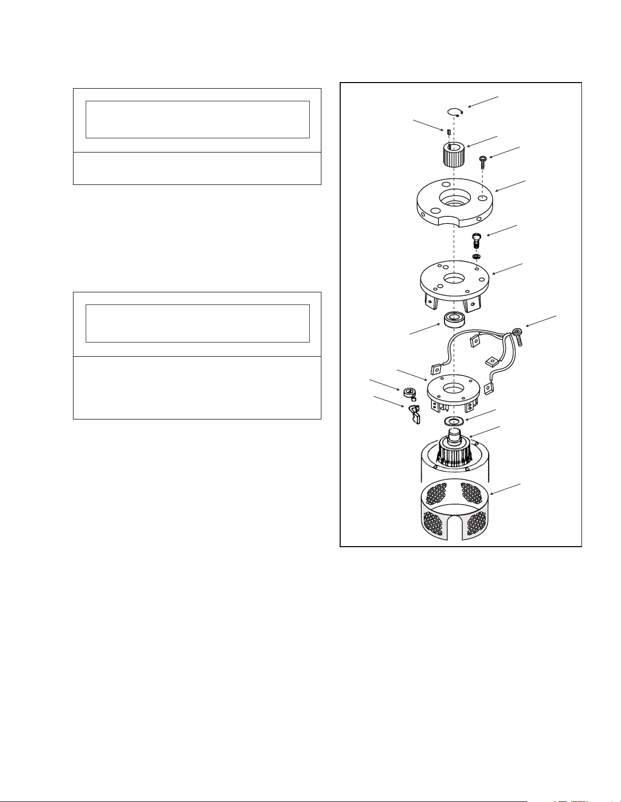
1
IMPORTANT
Make sure to remove the spring washer (13) and
save for reassembly.
10. Remove all brushes (12).
11. Remove the brush box assembly (10) and brush
springs (11).
12. Inspect the commutator assembly (14) for signs of
wear or burns. If the commutator shows signs of
wear, use fine sandpaper to resurface commutator
contact surfaces.
IMPORTANT
Make sure that no sandpaper particles or other
foreign matter enters the open motor.
If the commutator is burned, the motor must be fully
rebuilt or replaced.
13. Clean the commutator of sand particles and
reassemble the motor in reverse of disassembly
procedure.
2
3
4
5
6
7
8
9
10
11
12
13
14
14. Reinstall the steering arm.
15. Reconnect battery and test operate the truck.
15
4-5.4 If the motor needs to be replaced,
remove it from the transmission as follows:
1. Disconnect the battery.
2. Block load wheels to prevent the truck from
moving.
3. Elevate the front end lift truck and support the truck
on jack stands .
4. Remove motor compartment service covers.
5. Remove pivot tube cap (2, Figure 4-6) from the
pivot tube.
6. Label and disconnect wires leading to the
deadman switch and creep travel switch.
7. Remove four control head mounting screws and
control head, then disconnect control cable at the
round connector.
PPT0104-901336 4-15
8. Remove the cable clamp securing the control cable
9. Remove control cable from steering arm.
10. Remove the four screws securing the steering arm
11. Remove steering arm assembly.
12. Make sure the four cables to the drive motor are
Figure 4-18. Motor Commutator
inside the steering arm.
and remove the steering arm.
properly labeled Al, A2, Fl, and F2; then disconnect
the cables (1, Figure 4-19) from the drive motor.
I-7022
Page 34
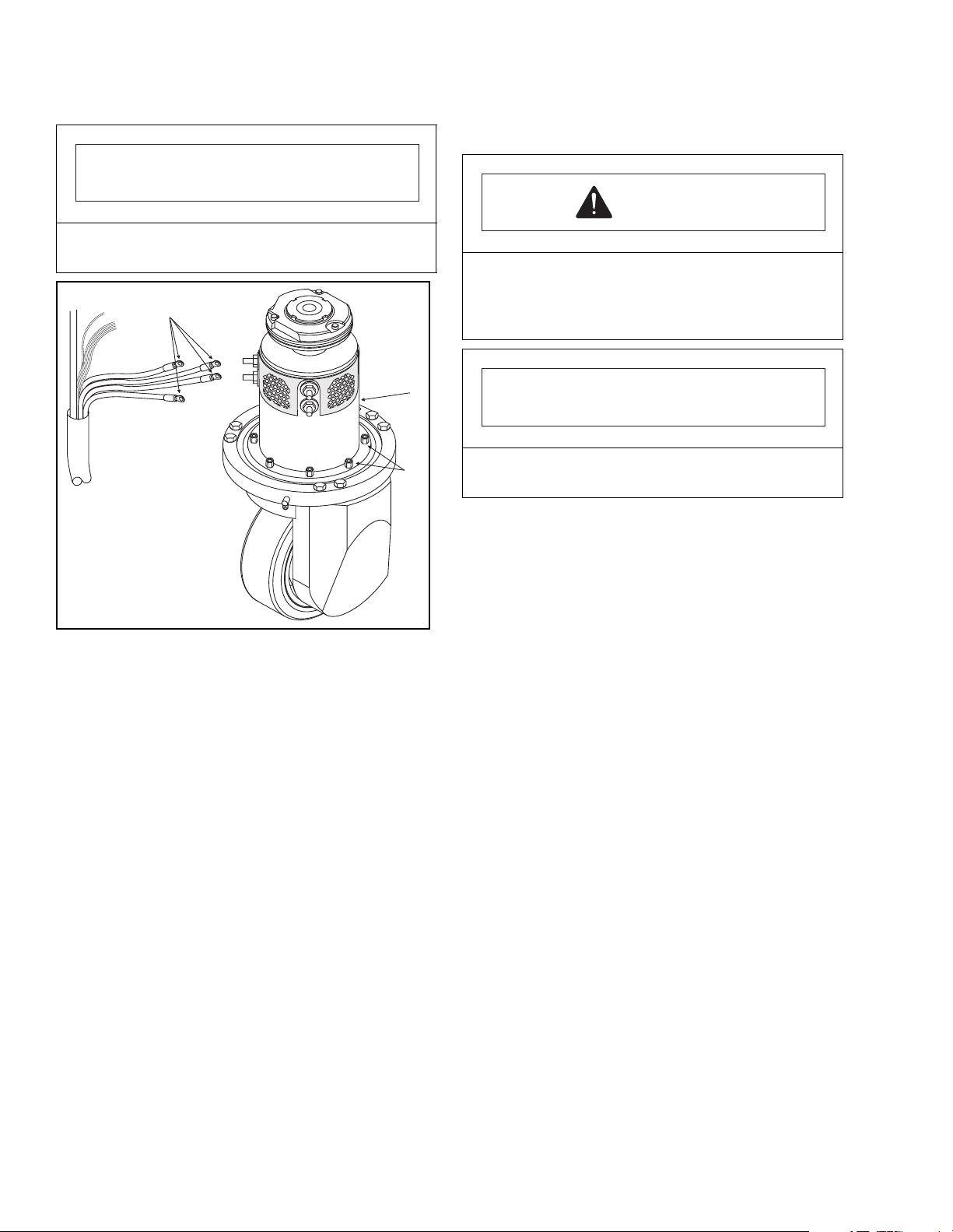
IMPORTANT
Note the location and routing of the control cables for
the reassembly process.
1
17. Reconnect the four cables to the drive motor.
Make sure to match the cable label to the terminal.
CAUTION
Make sure that wires do not contact sharp edges
of any assembly. Vibration can cause the
insulation to become damaged leading to an
electrical hazard.
3
2
I-7023
Figure 4-19. Motor Removal
13. Remove the eight hexhead cap screws (2) holding
the motor mounting plate to the transmission.
14. Remove the motor and mounting ring assembly
(3).
15. Install new drive motor onto transmission. Make
sure to align the splined shaft on the motor with the
splined receiver on the top of the transmission.
NOTE: When the motor has been removed, the
transmission sump will be exposed. Cover
opening to prevent foreign objects from
falling into the transmission.
16. Install the eight hexhead cap screws.
IMPORTANT
Make sure to relocate the motor control cables as
they were initially installed.
18. Reconnect the steering arm.
19. Reinstall control cable into steering arm and
secure with cable clamp.
20. Connect control cable using the round connector in
the control head.
21. Reinstall control head assembly.
22. Reconnect the battery.
23. Test operate the lift truck.
4-5.5 Transmission Assembly Removal.
NOTE: The transmission does not have any user
serviceable parts. If the transmission is the
cause of travel problems, it will need to be
replaced.
1. Disconnect battery.
2. Block load wheels to prevent the truck from
moving.
3. Elevate the drive end of the lift truck and support
the truck on jack stands .
4. Remove motor compartment service covers.
5. Remove pivot tube cap (2, Figure 4-6) from the
pivot tube.
6. Label and disconnect wires leading to the
deadman switch and creep travel switch.
7. Remove four control head mounting screws and
control head, then disconnect control cable at the
round connector.
4-16 PPT0104-901336
Page 35
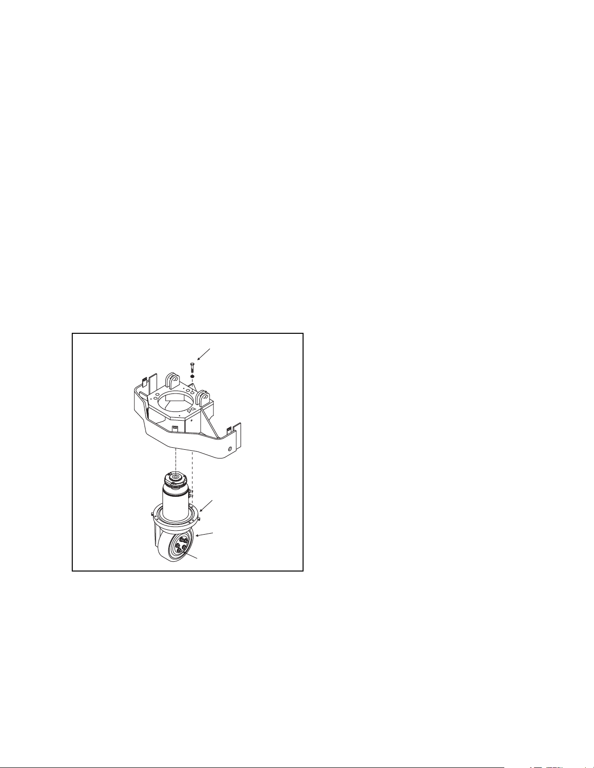
8. Remove the cable clamp securing the control cable
inside the steering arm.
9. Remove control cable from steering arm.
10. Remove the four screws securing the steering arm
and remove the steering arm.
11. Remove steering arm assembly.
12. Remove the drive motor. See Section 4-5.4.
NOTE: An alternate method is to remove the
motor and transmission assembly from the
truck, then remove the motor.
13. Support the transmission assembly and remove
the six bolts (1, Figure 4-20) securing the
transmission assembly to the truck and remove the
transmission and drive wheel assembly (2).
14. Remove the drive wheel (4) from the transmission
by removing the five lug nuts (3).
15. Install new transmission by reversing steps 2 - 14
above.
1
4-6. BASE, FRAME AND FORK SECTION
4-6.1 General
The base and frame section of the truck includes the
information plates, decals, fork section and load
wheels. Make certain that all decals remain on the
truck and are legible. If decals are damaged or
missing, they must be replaced.
4-6.2 Load Wheel Replacement
1. Raise the forks.
2. Block the drive wheel to prevent the truck from
rolling.
3. Jack up the forks to raise the load wheels off the
floor. Securely block the forks in the raised position
by positioning supports under both fork tips.
4. Drive the roll pin (3, Figure 4-21) from the load
wheel shaft (5) and pull the load wheel shaft out of
the load wheel housing (1). The load wheel and
both spacers (4) will drop free.
NOTE: Using a fine tip marker, draw a match
mark line across the end of the load wheel
shaft and onto the load wheel housing.
This line will assist in realigning the pin
hole in the shaft with the pin hole in the
wheel housing.
2
4
3
Figure 4-20. Transmission Removal
I-7024
5. Install new load wheel and bearing assemblies:
NOTE: If the load wheel is worn to approximately
1/8" thickness or is cracked or damaged,
replace the wheel and bearing assembly.
Big Joe recommends that both load wheel
assemblies be replaced at the same time.
a. Partially insert the load wheel shaft (5) into the
load wheel housing (1).
b. Install one spacer (4) onto the shaft, between
the arms of the load wheel housing (1).
c. Position the new load wheel and bearing
assembly (2) between the housing arms (1)
and slide the shaft (5) through the load wheel.
d. Install the remaining spacer (4) between the
load wheel and housing arm and push the
shaft completely into the housing.
e. Align the hole in the shaft with the hole in the
housing for the roll pin and install the roll pin.
6. Repeat installation procedures for the other load
wheel assembly.
PPT0104-901336 4-17
Page 36
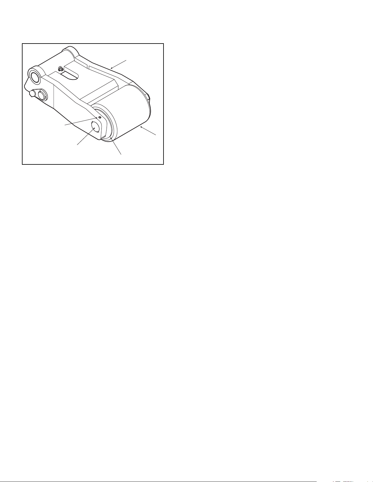
b. Pull wheel housing out of fork section to gain
access to the keeper pin (5). Remove lock
1
screw and keeper pin (5).
c. Drive out roll pin (2) from shaft (7). Remove
shaft from the power section end of the pull
rod.
NOTE: It may be necessary to either extend
or retract the hydraulic cylinder to gain
access to the roll pin.
3
2
5
4
Figure 4-21. Load Wheel Assembly
I-7026
4-6.3 Frame Assembly: Fork Section and Lift
Linkage Repair and Replacement.
1. Lift Linkage repair and replacement:
a. Lift complete truck to height sufficient to permit
access to lift linkage under forks. Provide
blocking under power section frame and at
tips of forks.
b. Remove screws (11, Figure 4-22) that secure
the lower support pins (9) to the pivot
weldment (8). Remove both support pins from
the pivot weldment.
c. Drive roll pin (2) from pivot weldment (8).
d. Remove lift link support pin (5) from pivot
weldment.
NOTE: Using a fine tip marker, draw a match
mark line across the end of the lift link
support pin and onto the pivot
weldment. This line will assist in
realigning the pin hole in the shaft with
the pin hole in the link lift shaft.
e. Remove the roll pin (2) and remove the pivot
shaft (7) from power section. Remove pivot
weldment (8) and lower the pull rod assembly
(6) and link shaft to the floor.
f. Replace worn or damaged lift link components
g. Reassemble lift linkage by reversing steps "a"
through "e" above.
2. Pull Rod Removal and Installation (Figure 4-22)
a. Remove roll pin (2) from the fork section and
remove shaft (1).
Using a fine tip marker, draw a match
mark line across the end of the lift link
support pin and onto the link lift shaft.
This line will assist in realigning the
pin hole in the shaft with the pin hole
in the link lift shaft.
d. If replacing one pull rod assembly (6), take the
initial measurement from the remaining good
rod. Adjust the new rod assembly to match the
measurement. If replacing both pull rods,
rotate the turnbuckles to set a 37 ¾"
measurement on the 48" fork.
e. Install wheel housing end of replacement rod
first. Secure pull rod to wheel HSG assembly
using keeper pin (5). Secure keeper pin with
lock screw . Shim as needed (3).
f. Install the other end of the pull rod into the
pivot weldment and secure with shaft (7).
Secure shaft (7) with roll pin (2). Shim as
needed (3).
NOTE: If the holes do not line up, rotate the
turnbuckle until the holes align
properly.
g. Rinstall shaft (1) and roll pin (2) to reconnect
pull rod to wheel HSG assembly.
h. Insert pivot shaft (9) to secure the pull rod
assembly to the pivot tube. Secure pivot shaft
with screw (11) and washer (10). Shim as
needed (3).
i. Visually compare the position of the load
wheels (4). If necessary, adjust turnbuckle on
new pull rod to match position of the other load
wheel.
j. Remove supports from truck and lower the unit
to the ground. Check to make sure that both
wheel housings retract at the same time and
that the forks are level when the lift truck is fully
raised.
k. After confirming adjustment, tighten jamb nut
against the turnbuckle on the new pull rod.
4-18 PPT0104-901336
Page 37
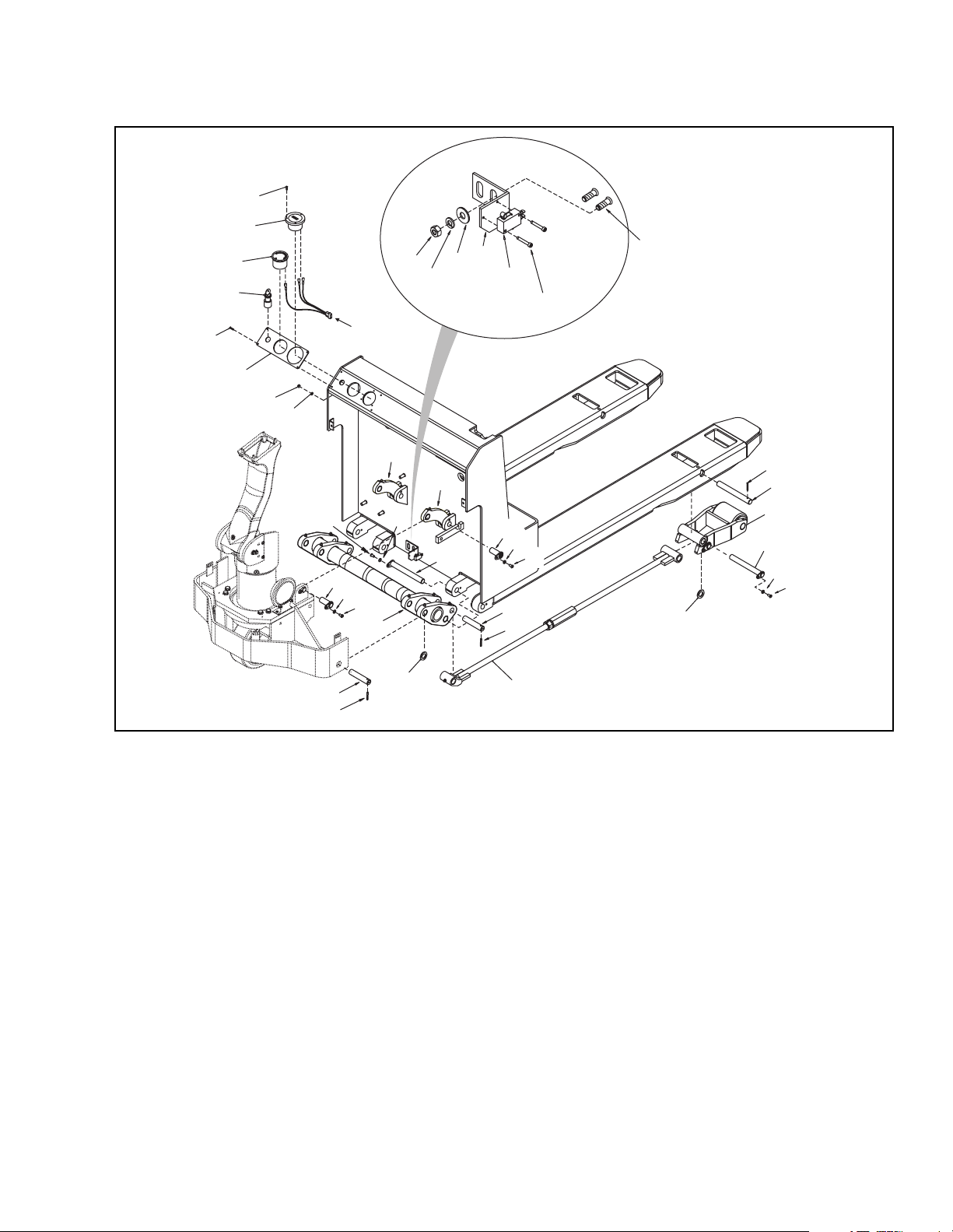
24
27
THREADED STUDS WELDED
TO MOTOR COMPARTMENT
WALL.
26
25
21
10
19
18
17
16
24
TO
CONTROLLER
23
22
14
12
12
11
10
9
13
10
11
8
3
7
2
Figure 4-22. Lift Link Assembly
3. Power Section Frame Repair:
a. Repair of power section frame is limited to
chasing damaged threads and welding of any
broken welds.
b. Replace a worn or damaged U-clip nuts as
needed.
Removal of components mounted on power section
frame may be necessary to complete repairs/welding of
frame, refer to table of contents for identification of
instructions on such components.
13
2
1
4
10
5
11
10
11
7
2
3
6
I-7049
PPT0104-901336 4-19
Page 38
4-7. ELECTRICAL
4-7.1 Battery Removal and Replacement
1. The batteries are enclosed in the battery
compartment.
2. Remove the battery compartment cover by
removing the lock handle (1, Figure 4-23), and
lifting the battery compartment cover (2) off the lift
truck.
WARNING
4-7.2 Battery Cable Assemblies Replacement.
1. Disconnect batteries (Section 4-7.1).
2. Trace the cable (1, Figure 4-24) that needs to be
replaced from the battery compartment into the
motor compartment.
3. Remove the cable from the appropriate insulated
stand-off (2).
NOTE: Note the additional cables (3, 4) attached
to the insulated stand-off.
4. Remove the cable assembly from the truck.
NOTE: Cable connectors are factory applied and
are not individually replaceable.
• Batteries available for the lift truck vary in
weight. A suitable hoist and sling
arrangement must be used to prevent injury.
• Batteries may contain electrolyte. Use
extreme caution when handling lead acid
batteries.
3. Disconnect the battery plug (3) from the connector.
4. Disconnect battery cables (4 and 5) from batteries.
5. Remove batteries (6) from lift truck.
CAUTION
The 6V battery pack with charger and the 24V
flooded cell industrial battery packs will require
the use of a lifting device to safely remove the
battery.
NOTE: • The PPT 45 has three optional battery sets,
a single 24V flooded cell industrial battery
(10, Figure 4-23), a set of 4 6V batteries (9)
or a set of two 12V batteries (8).
5. Route replacement cable assembly from the
battery compartment into the motor compartment.
CAUTION
Make sure that wires do not contact sharp edges
of any assembly. Vibration can cause the
insulation to become damaged leading to an
electrical hazard.
6. Attach the new cable to the appropriate insulated
stand-off.
NOTE: Make sure to reattach the additional
cables removed from the insulated standoff.
7. Reconnect cables to the battery.
• Each of the battery sets is enclosed in a
removable case. Removal of the battery
packs requires that the electrical cables to
the lift truck be disconnected. When the
cables have been disconnected, the
batteries or battery case can be removed
from the lift truck.
• Depending on the battery installed, spacers
(7) may be utilized to secure the batteries.
Make sure to replace the spacers in the
appropriate locations.
6. Install new batteries and reconnect power cables.
4-20 PPT0104-901336
Page 39
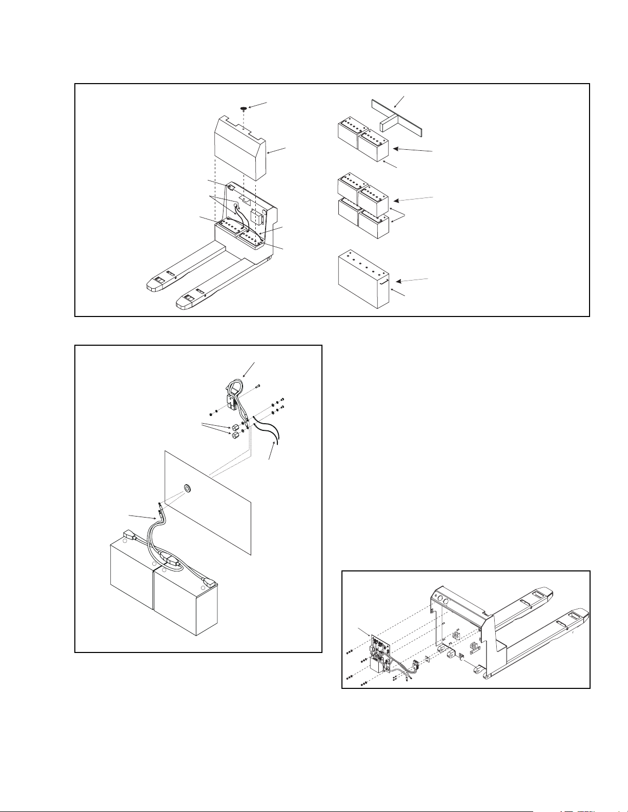
1
7
2
3
5
6
4
6
8
9
10
Two 12V batteries with
charger built into truck
Four 6V batteries with
charger built into
battery pack
Single 24V (flooded cell)
industrial battery
I-7027
Figure 4-23. Battery Installation
4-7.3 Transistor/Contactor Panel
3
2
NOTE: Erratic operation of the truck may be caused
by defective controller components. Before
removing the contactor control panel, perform
troubleshooting procedures per paragraph 6-3,
to determine corrective action to be taken.
1. Contactor Panel Removal.
4
1
-
+
-
+
Figure 4-24. Battery Cable Replacement
a. Disconnect the battery.
b. Remove screws (5, 7 and 9, Figure 4-6), lock-
washers, flat washers, and motor compartment
covers (6, 8 and 10).
c. Refer to Figure 4-25 and tag and disconnect all
electrical wires and cables, which connect to
the contactor panel (1).
d. Remove nuts and lockwashers to release and
remove the contactor panel assembly.
1
I-7028
I-7029
Figure 4-25. Contactor Panel Removal
PPT0104-901336 4-21
Page 40
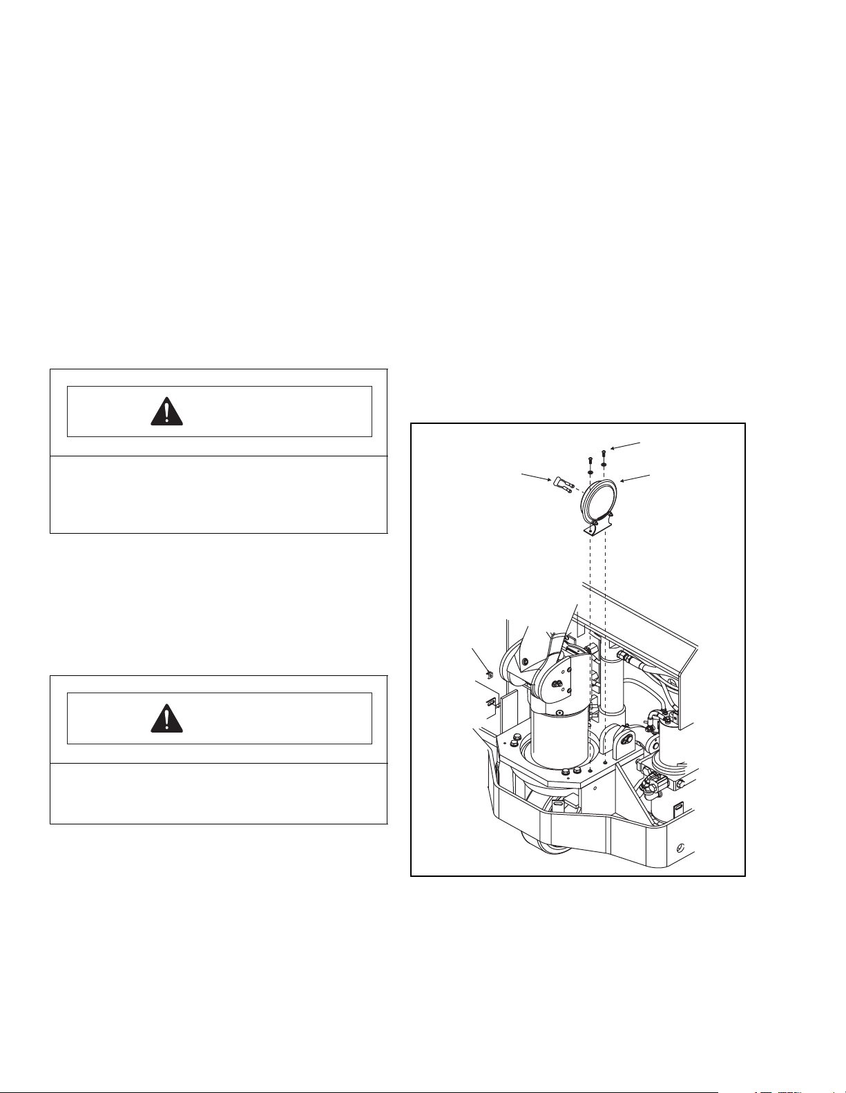
2. Contactor Panel Disassembly
a. Refer to Figure 4-27 for the location and
identity of the major replacement components
mounted on the panel and remove defective
part.
NOTE: The forward and reverse contactors
used on this panel are not repairable
and must be replaced if defective.
3. Contactor Panel Reassembly
a. Install replacement parts in same location and
orientation as the defective part removed.
b. Connect all electrical wires and cable
assemblies, as noted during removal and
shown on Figure 4-27.
4-7.4 Horn Replacement.
To replace the horn, proceed as follows:
1. Tag and disconnect all electrical connections from
horn..
2. Remove nuts, lockwashers and flat washers (2,
Figure 4-27) to release and remove the horn (1).
3. Check the spike suppressor assembly (3) for
damage. If any part is damaged, the entire spike
suppressor assembly must be replaced.
4. Install horn (1) and secure with nuts, flat washers
and lockwashers (2).
5. Connect all electrical wires to the horn, as noted
during removal.
6. Install motor compartment (service) cover and.
7. Connect the battery.
CAUTION
Make sure that wires do not contact sharp edges
of any assembly. Vibration can cause the
insulation to become damaged leading to an
electrical hazard.
4. Contactor Panel Reinstallation.
a. Install contactor panel and secure with lock-
washers and nuts.
b. Refer to Figure 4-27 and wiring diagrams
(Figure 4-30). Connect all electrical wires and
cables to the contactor panel, as noted during
removal.
CAUTION
Make sure that wires do not contact sharp edges of
any assembly. Vibration can cause the insulation to
become damaged leading to an electrical hazard.
2
3
1
c. Install motor compartment (service) cover and
secure.
d. Connect the battery.
Figure 4-26. Horn Replacement
4-22 PPT0104-901336
Page 41

14
MAX
15AMP
1
POS
4
1
1
FWDREV
3
NEG
POS
POS
A2
NEG
MAX 15AMP
3
120 AMP
MAXIMUM
8
2
Figure 4-27. Contactor Panel Replacement Parts
4-7.5 Battery Charger.
NOTE: If the lift truck is equipped with a heavy duty
24V steel case flooded cell industrial battery,
the charger is remotely located. The charger
for the trucks equipped with two 12V batteries
is built into the truck and the charger for trucks
equipped with the 6V battery pack is built into
the battery pack.
4-7.5.1 12V Light Duty Gel-Cell Batteries
The light duty Gel-Cell battery charger (1, Figure 4-28)
is split into two components. The transformer is
mounted below the contactor panel in the motor
compartment. The controller is mounted in the upper
right side of the power section frame. The power plug
(2) is located above the battery cover. The charge
status indicator, which built into the controller, is
readable through the opening in the top surface of the
battery cover.
To charge the batteries, plug the charger into 110 V AC
power.
4
5
6
7
NEG
I-7030
4-7.5.2 Medium Duty 6V Battery Pack
The medium duty battery pack is a self contained unit
with batteries and charger built into the battery case.
The charger (3, Figure 4-28) is split into two
components, the transformer in the lower section of the
battery case and the controller located at the top of the
case. The power plug (2) is located on the front of the
battery case. The charge status indicator, which is built
into the charger controller, is readable through the front
of the battery case, next to the power plug.
To charge the battery pack, move the battery connector
from the truck plug into the battery pack plug, and then
plug the charger into 110 V AC power.
4-7.5.3 Heavy Duty 24V Steel Case Flooded
Cell Industrial Battery (Not shown)
The 24V heavy duty industrial battery is charged with a
remote charger. To charge the battery, unplug the
battery connector from the truck plug and plug the
charger into the charge plug.
PPT0104-901336 4-23
Page 42
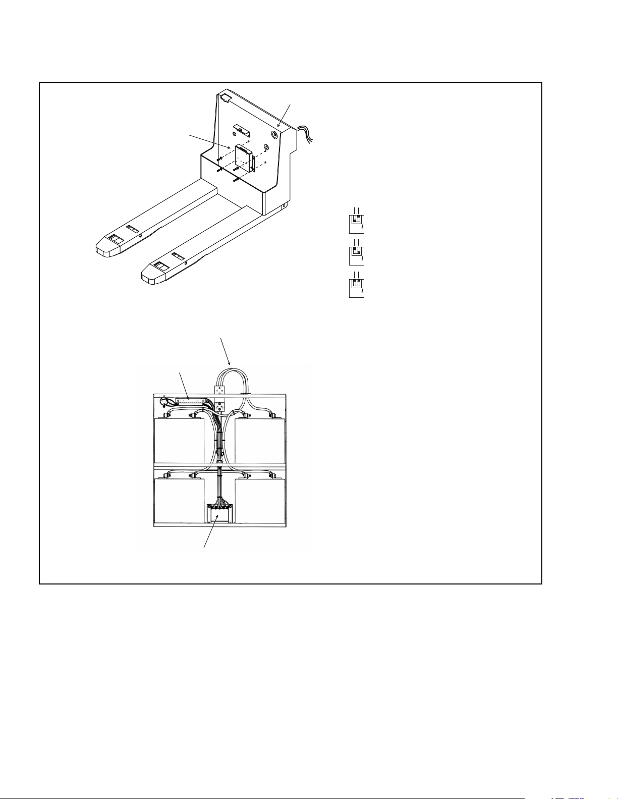
2
1
Set dip switches on charger
logic board as required by
battery configuration
Default setting -
2
1
ON
Gel Cell (GMF) Batteries
Two 12V Batteries W/truck Mounted Charger
4
3
Absorbed
2
1
ON
Cell (AMF) Batteries
Flooded Cell Battery
2
1
ON
Glass Mat
3
Four 6V Battery Pack and Charger
Figure 4-28. Battery Pack and Charger Variations
4-7.6 BATTERY DISCHARGE INDICATOR.
Replacement parts for the optional battery discharge
indicator are detailed in Figure 7-20. Refer to the wiring
diagram to help ensure proper connections.
4-7.6.1 Battery Discharge Indicator Replace-
ment.
1. Operation of the battery discharge indicator (1,
Figure 4-29) may be checked by comparing its
reading against a hydrometer. Indicator should
4-24 PPT0104-901336
show a full charge when hydrometer shows a
specific gravity of 1.260 to 1.275.
NOTE: If the Discharge Indicator does not
function properly, check the 5 Amp fuse
located on the rear side of the indicator
before replacing the indicator. The
indicator must be removed from the
display panel to enable access to the fuse.
If the fuse has not blown, replace the
discharge indicator as follows:
I-7032-2
Page 43
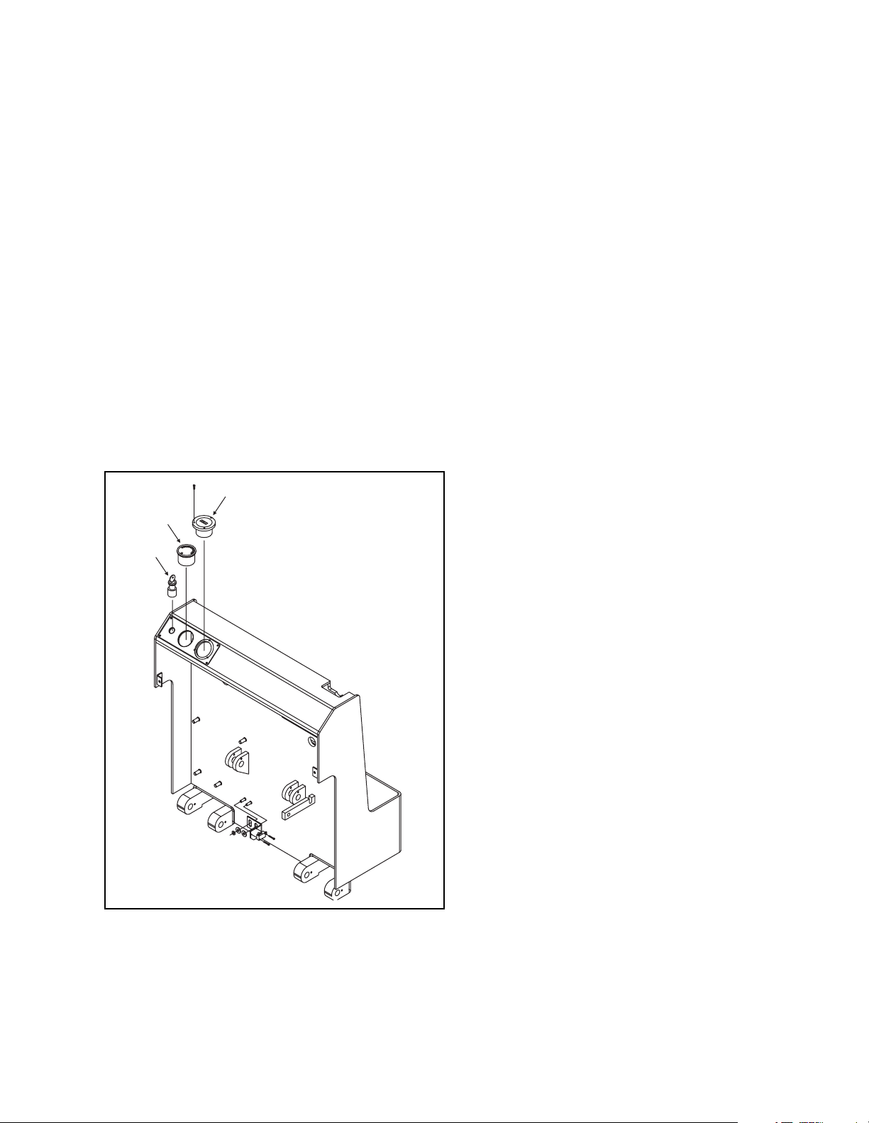
2. To replace the battery discharge indicator (1),
proceed as follows:
a. Disconnect the battery.
b. Tag and disconnect terminals behind the
indicator.
c. Remove two lock nuts and U-bracket to
release and remove the indicator.
NOTE: Replacement indicator will be
furnished with nuts and U-bracket.
The original U-bracket may be reused,
if not damaged.
d. Install new battery discharge indicator (1) and
secure with supplied U-bracket and nuts. If
required, trim the U-bracket legs to proper
length, or reuse the old u-bracket.
e. Reconnect terminals as noted during charge
indicator removal.
f. Connect the battery.
2
1
3
4-7.7.1 Hour meter Replacement.
1. Operation of the hour meter (2) may be checked
against a watch.
2. To replace the hour meter (2), proceed as follows:
a. Disconnect the battery.
b. Remove the 3 screws, lock washers and nuts
found around the "bezel" or outer ring of the
meter and remove the hour meter from the panel.
c. Tag and disconnect the terminal and diode
from the hour meter.
d. Reconnect the terminal and diode to the new
hour meter (2).
e. Install the new hour meter into the panel and
secure with the 3 screws, lock washers and
nuts.
f. Connect the battery.
4-7.8 KEYSWITCH.
The optional key switch is item 3, Figure 4-29. The key
switch installation is accomplished by inserting the
supplied wiring into wire number 3, of control panel
harness, at the slip-on connector of the in-line fuse.
Refer to the wiring diagram to help ensure proper
connections.
I-7035
Figure 4-29. Indicator Replacement
4-7.7 HOURMETER.
The hour meter (2, Figure 4-29) is available for
attachment to the motor circuits to indicate use of the
drive and lift functions to help ensure proper
connections.
4-7.9 Wire Harness Testing.
1. Wire harnesses are illustrated and identified on the
figures in this manual containing the components
they are associated with. As an aid to testing,
individual wires in each harness have their wire
numbers permanently marked on both ends. Refer
to the wiring diagram shown in Figure 4-30.
2. Testing procedures are as follows:
a. Disconnect the battery.
b. Tag and disconnect electrical wires as
necessary.
c. Disconnect plug(s) and/or receptacle(s), if any
d. Using a multimeter, check all individual wire
leads for continuity. Continuity must exist in
each individual wire lead.
3. If a wire harness fails continuity test, it must be
replaced. Make careful note of harness routing,
and location of any clamps or wire ties before
removing. Route new harness, and install any
clamps or wire ties, as noted during removal.
4. Connect electrical wires, as noted during removal.
5. Connect any plug(s) and/or receptacle(s), as noted
during removal.
6. Connect the battery.
PPT0104-901336 4-25
Page 44
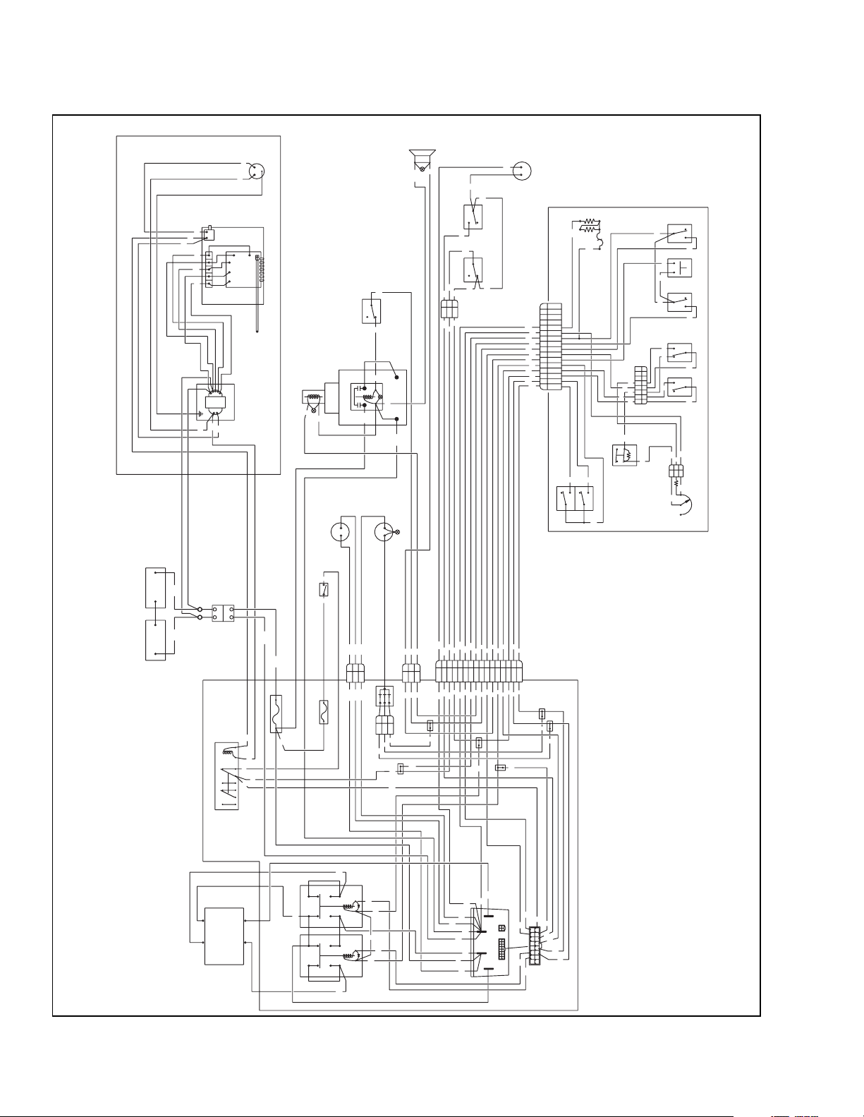
BLACK
BLACK
BLACK
WHITE
WHITE
HORN
ELECTRIC
BRAKE
MALE OUTLET
19
120 VAC
+
GR
-
20
GREEN
BLUE
BOARD
LOGIC
WHITE 18
TRANSFORMER
BLACK
LOGIC BOARD HEATSINK/ENCLOSURE
THERMISTER
120 VAC BATTERY CHARGER CIRCUIT
WHITE
RMT LWR
SOLENOID
VALVE
9
9
DISCHARGE
INDICATOR
33
KEYSWITCH
-
+
PUMP MOTOR
SOLENOID
SWITCH
LIFT LIMIT
N.O.
POS
METER
HOUR
8
COM
N.C.
8
8
-
+
BREAKER
CIRCUIT
19
19
19
16
BLACK
17
WHITE
RED
18
TERMINAL
STRIP
WHITE
WHITE 17
WHITE 16 (BLUE)
BLACK
RED
BLACK
RED
GREEN
20
19
20
BLACK
RED
+
6
NEG
15
33
15
3
1
2
3
15
3
PUMP MOTOR
POS
NEG
NEG
NEG
16
-
+
3
3
SWITCH
COM
CREEP
N.O.
N.C.
3
SWITCH
DEADMAN
COM
N.O.
N.C.
3
3
CONTROL HEAD
N.C.
COM
12
10
CONDITIONING
COLD
16
15
14
13
12
12
11
11
10
10
9
9
8
8
7
7
6
6
5
5
4
4
3
3
2
2
1
1
10
LIFT
N.O.
8
6
HORN
10
N.C.
LOWER
10
COM
N.O.
9
SLOW REV
N.O.
6
COM
12
N.C.
8
7
6
4
7
12
365
2
4
1
3
7
REVERSING
N.O.
4
COM
N.C.
3
12
2.7K
LIMIT SWITCH
2
N.O.
REVERSE
HIGH SPEED
1
N.O.
N.C.
N.C.
FORWARD
COM
COM
11
12
6
12
2
1
3
5K SPEED CONTROL
1.2K
11
POTENTIOMETER
12
5
506179
WIRING DIAGRAM-PPT45, XSTR
BATTERIES
-
+
NEGPOS
-
STANDOFFS
+
+
-
-
CONNECTOR
BATTERY
NEG
POS
NEG
POS
NEG
3
2
1
POS
NEG
120 AMP
WHITE
BLACK
19
A
AC CHARGING RELAY
B
1
7
34
96
NONONC NC
3
20
3
3
3
NEG
15 AMP
DIODE ASSY
6
8
9
3
2
1
6
8
9
3
2
1
8
1
2
10
3
3
12
16
10
4
98765
1011121314
10
2
1
123456789
123456789
AND CONTACTOR PANEL
SOLID STATE CONTROL
1
2
5
5
3
11
3
15
15
16
11
15
3
12
16
3
8
F2
A1
12
16
NEG
NEG
NEG
NEG
POS
POS
POS
11
M-
B-
B+
A2
3
5
7
16
8
16
8
1
9
15
14
4
1315
1
1112
237
2
14
13
2. SEE ELECTRICAL SCHEMATIC506180.
1. DASHED CIRCUITS ARE OPTIONAL ITEMS.
NOTES:
-
REV
A1
A2
F1
F2
MOTOR
DRIVE
A2
FWD
13
5
+
5
14
5
+
F1
I-7038
Figure 4-30. Electrical Schematic
4-26 PPT0104-901336
Page 45
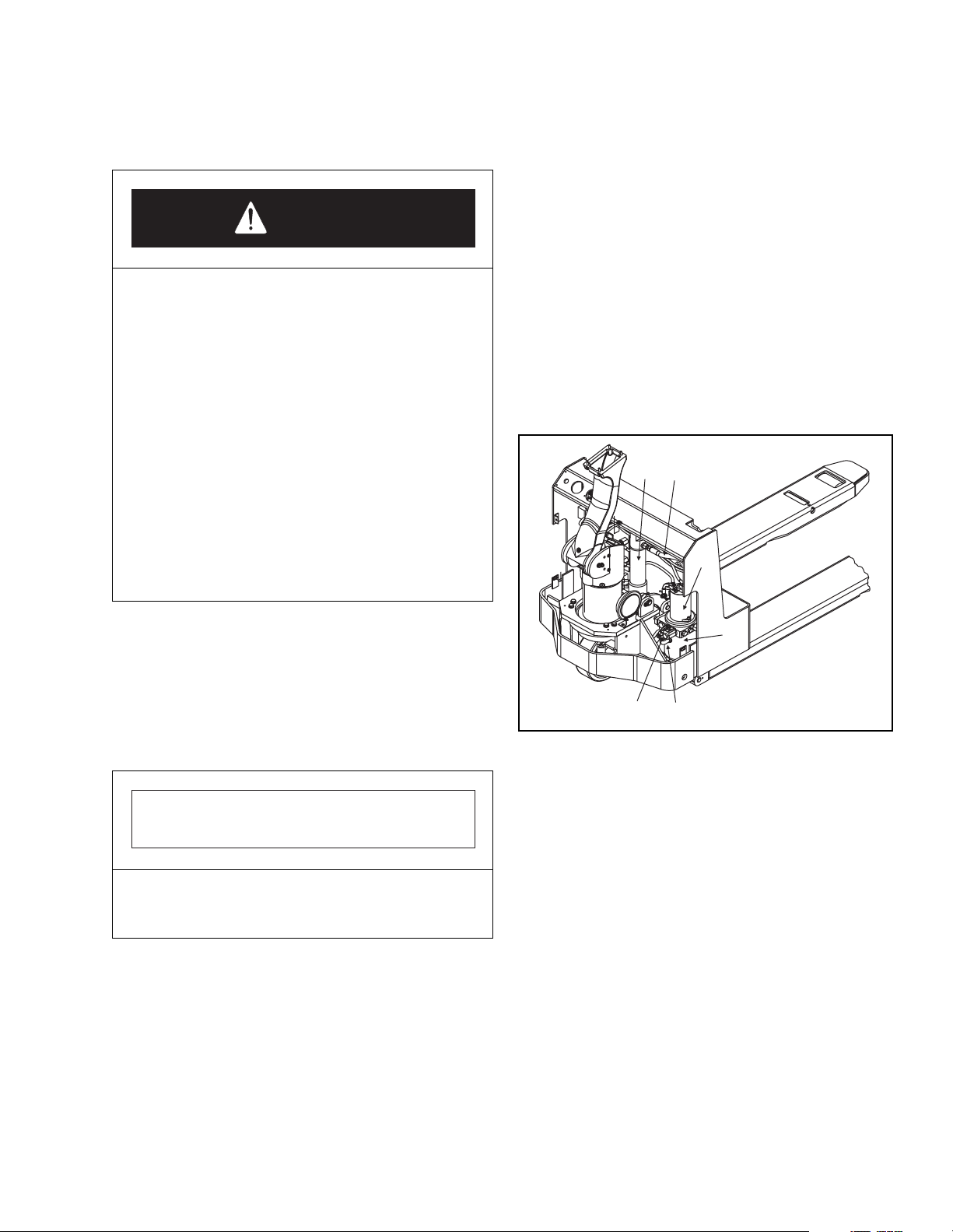
4-8. HYDRAULICS.
4-8.1 Line and Fitting Replacement.
DANGER
• Hydraulic oil under pressure can penetrate
the skin. It is toxic and can damage tissue.
Always use a piece of wood or cardboard to
check for suspected hydraulic leaks. NEVER
USE YOUR HANDS. Obtain immediate
medical attention from a medical provider
knowledgeable with hydraulic fluid injuries if
pressurized hydraulic fluid pierces the skin.
Failure to obtain prompt medical assistance
could result in gangrene or other serious
damage to tissue.
• When forks are raised, pressure exists in the
hydraulic system lines and fittings. To
ensure release of pressure, forks must be
fully lowered and the battery disconnected
before performing any maintenance on the
hydraulic system.
4. Refer to Figure 4-31 and remove leaking line (2) or
fitting and replace it with a new line or fitting.
5. Remove the vent plug and elbow (5 & 6, Figure 4-
31). Check level of hydraulic oil. Hydraulic oil must
be one inch below bottom of elbow (5). If required,
add hydraulic oil to bring to proper level. Use
hydraulic oil listed in Table 3-3.
6. Reinstall the vent plug (6).
7. Reconnect the battery and operate the lift lower
button to refill cylinder and lines with hydraulic oil.
8. Lower forks fully and disconnect battery.
9. Recheck hydraulic oil level, see Steps 5 and 6.
10. Install motor compartment (service) cover.
11. Reconnect the battery.
1
2
3
NOTE: Leaking hydraulic fittings may be repaired by
simply tightening the fittings. If this does not
repair the leak, the fittinìg or line must be
replaced.
1. Lower forks fully.
2. Disconnect battery (Section 4-7.1).
3. Remove motor compartment (service) cover.
IMPORTANT
Hydraulic oil can damage parts. Wipe off any oil
immediately. Provide a container under line or fitting,
before disconnecting.
4
5
6
Figure 4-31. Hydraulic System
I-7033
4-8.2 Hydraulic Pump, Motor, and Reservoir
Assembly.
The hydraulic pump, motor, and reservoir assembly
can be disassembled and repaired. The motor and
control valves can be repaired, however, a defective
pump must be replaced as a complete unit. Proceed as
follows to remove and disassemble the hydraulic
pump, motor, and reservoir assembly
PPT0104-901336 4-27
Page 46
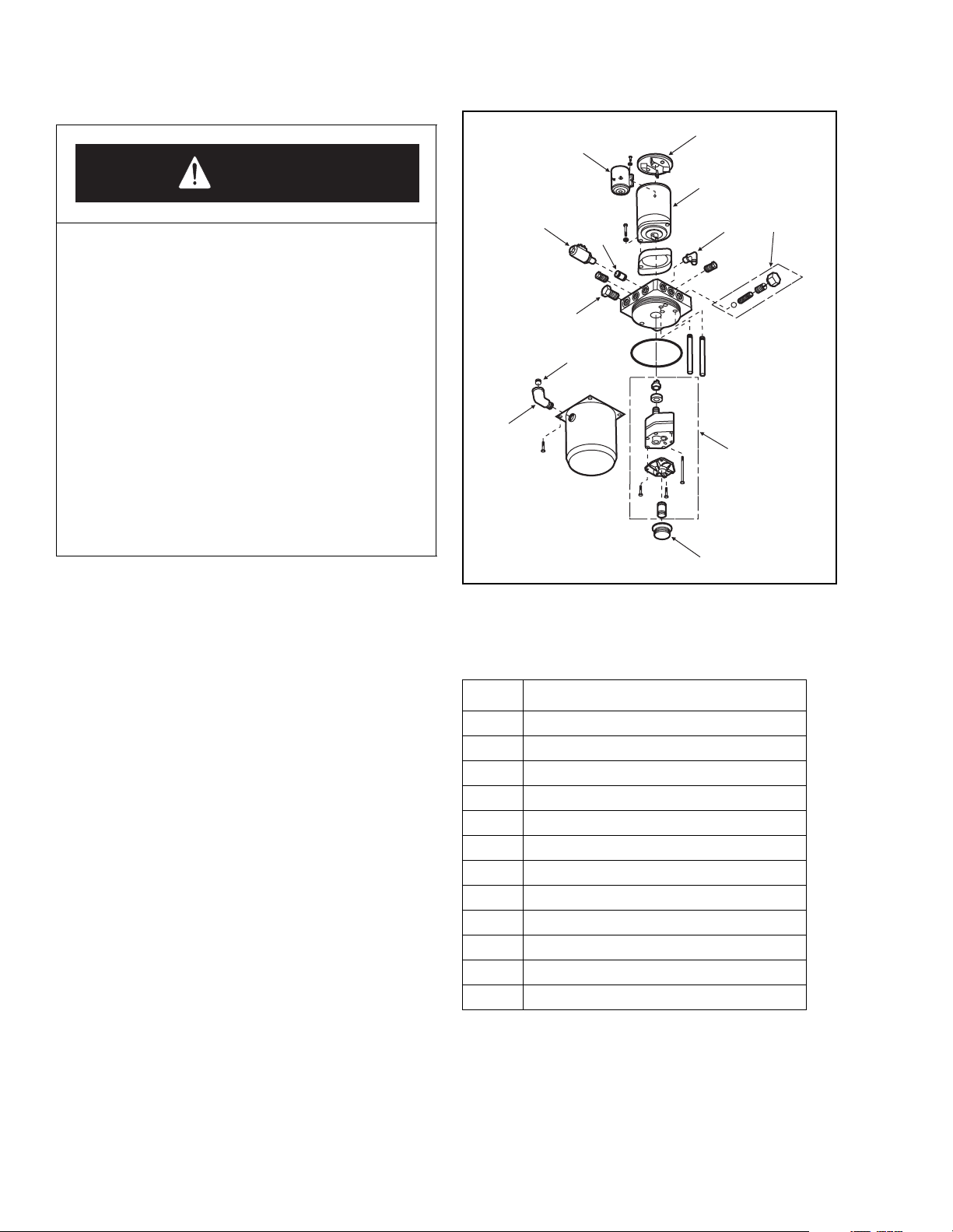
.
1
12
DANGER
• Hydraulic oil under pressure can penetrate
the skin. It is toxic and can damage tissue.
Always use a piece of wood or cardboard to
check for suspected hydraulic leaks. NEVER
USE YOUR HANDS. Obtain immediate
medical attention from a medical provider
knowledgeable with hydraulic fluid injuries if
pressurized hydraulic fluid pierces the skin.
Failure to obtain prompt medical assistance
could result in gangrene or other serious
damage to tissue.
• When forks are raised, pressure exists in the
hydraulic system lines and fittings. To
ensure release of pressure, forks must be
fully lowered and the battery disconnected
before performing any maintenance on the
hydraulic system.
1. Lower forks fully and disconnect battery.
2. Remove screws and remove motor compartment
(service) cover.
3. Tag and disconnect all electrical wires from the
pump, motor, and reservoir assembly (3 & 4,
Figure 4-31).
4. Remove hose assembly (2) and adapter (9, Figure
4-32).
5. Remove screws, lockwashers and flat washers to
release and remove pump/motor assembly (3 & 4,
Figure 4-31).
6. Remove vent plug (7, Figure 4-32) and drain
hydraulic oil from reservoir into a clean bucket or
suitable container.
7. Refer to Figure 4-32 for parts relationship and
Table 4-2 for parts identification. Replace damaged
components.
2
10
11
3
9
8
7
6
4
5
Figure 4-32. Hydraulic Pump/Motor Assembly
Table 4-2. Hydraulic Pump/Motor
Parts IdentificationI
Item Description
1 Cap/Brush Kit
2 24 V Motor
3 Relief Valve Assembly
4 Pump Assembly
5Filter
6 Elbow
7 Breather Plug
8 Check Valve
9 9/16" Elbow
10 Solenoid Release Valve
11 Flow Regulator Valve
12 24 V Solenoid
I-7034
4-28 PPT0104-901336
Page 47
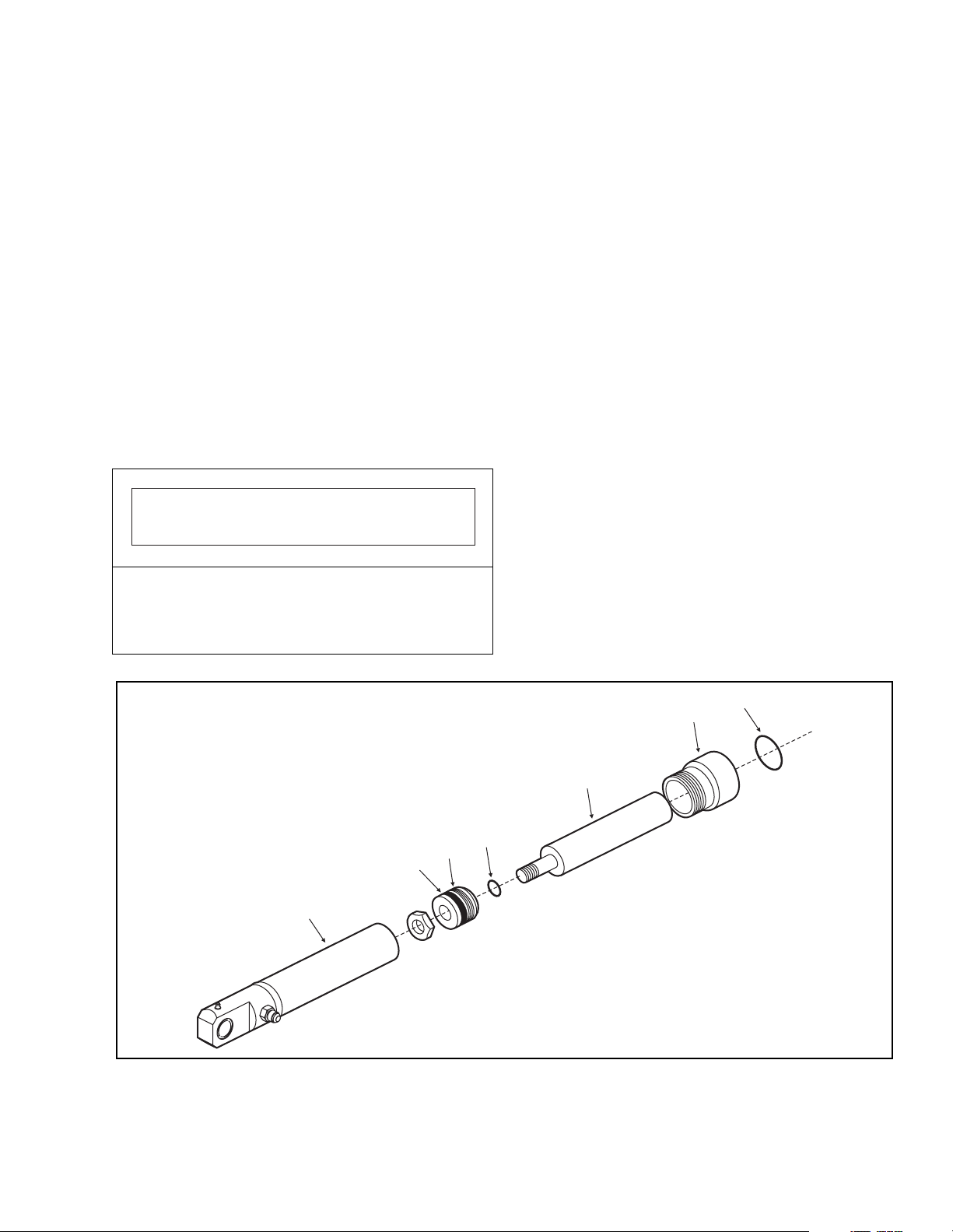
4-8.3 Lift Cylinder Removal.
1. Disconnect batteries.
2. Lift complete truck to height sufficient to permit
access to under side of hydraulic cylinder (1,
Figure 4-31). Provide blocking under power section
frame and at tips of forks.
3. Remove hydraulic supply line (2). Plug open end
of hydraulic line to prevent fluid loss.
NOTE: The cylinder may have some hydraulic oil
in it.
4. Remove screw from the lower cylinder support.
NOTE: This screw is reached from below.
5. Remove upper keeper pin.
6. Remove cylinder.
7. Install new cylinder by reversing Steps 3 - 5.
IMPORTANT
4-8.4 Lift Cylinder Repair.
To rebuild or replace components in a lift cylinder,
proceed as follows:
1. Secure the lift cylinder in a vise, clamping lightly at
the base of the cylinder.
2. With spanner wrench, remove the cylinder head (2,
Figure 4-33) from the cylinder weldment (7).
3. Withdraw the cylinder rod (3) from the cylinder
NOTE: If the cylinder weldment (7), cylinder rod
(3), or cylinder head (2) is damaged, the
entire lift cylinder must be replaced.
4. Replace all wipers, seals and damaged or worn
pads (1, 4, 5, 6).
5. Coat all parts with the correct hydraulic oil (Table 3-3).
6. Insert cylinder rod (3), with attached pads, wipers
and seals into the cylinder weldment (7).
7. Install cylinder head and tighten to 5-7 lbs/ft.
When reinstalling the hydraulic supply line make
sure that it does not touch the electrical stand-off or
any other component that could cause wear and
premature failure.
5
6
7
2
1
3
4
I-7061
Figure 4-33. Lift Cylinder Assembly
PPT0104-901336 4-29
Page 48

4-8.5 Hydraulic Pressure Adjustment.
The relief valve is factory set to open at the rated
pressure setting for the pump (not to exceed 2,575 psi)
and rarely needs adjusting.
DANGER
• Hydraulic oil under pressure can penetrate
the skin. It is toxic and can damage tissue.
Always use a piece of wood or cardboard to
check for suspected hydraulic leaks. NEVER
USE YOUR HANDS. Obtain immediate
medical attention from a medical provider
knowledgeable with hydraulic fluid injuries if
pressurized hydraulic fluid pierces the skin.
Failure to obtain prompt medical assistance
could result in gangrene or other serious
damage to tissue.
• When forks are raised, pressure exists in the
hydraulic system lines and fittings. To
ensure release of pressure, forks must be
fully lowered and the battery disconnected
before performing any maintenance on the
hydraulic system.
4. Activate pump motor and observe reading on
pressure gauge. If pressure reading is between
2,475 and 2,575 psi, the relief valve is functioning
properly and does not need adjustment. If pressure
reading is below 2,475 psi or above 2,575 psi,
proceed as follows to adjust relief valve:
IMPORTANT
Do not set pressure too high or hydraulic system may
be damaged. Factory recommended limits of 2,475 to
2,575 psi should be observed. Under no circumstances
should pressure be set above 2,575 psi.
5. Remove protective cover nut from relieve valve
assembly (3, Figure 4-32) to gain access to
adjusting screw. With pump motor running,
observe pressure gauge and set pressure between
2,475 and 2,575 psi by turning adjusting screw (3)
clockwise to increase pressure or
counterclockwise to decrease pressure.
6. Deactivate pump motor, disconnect pressure
gauge, and reconnect hose.
7. Install motor compartment (service) cover.
If you suspect that the relief valve is malfunctioning,
perform the following procedures:
1. Lower forks as far as they will go.
2. Remove motor compartment (service) cover.
3. Disconnect hose (2, Figure 4-31) from elbow (9,
Figure 4-32) at pump and connect a pressure
gauge of adequate range (0-3,000 psi) to the
elbow.
4-9. DECALS AND TRIM.
4-9.1 Painting Requirements.
Clean all dirt, scale, and other foreign matter from
surfaces to be painted. Touch up paint on frames and
pull rods with yellow enamel (Big Joe P/N 901201).
Touch up paint on remaining parts with black satin
enamel (Big Joe P/N 901202).
4-9.2 Decals and Plates.
Refer to Figure 1-1 for location and identification of
decals and information plates. Make sure decals and
plates are legible and securely attached.
4-30 PPT0104-901336
Page 49
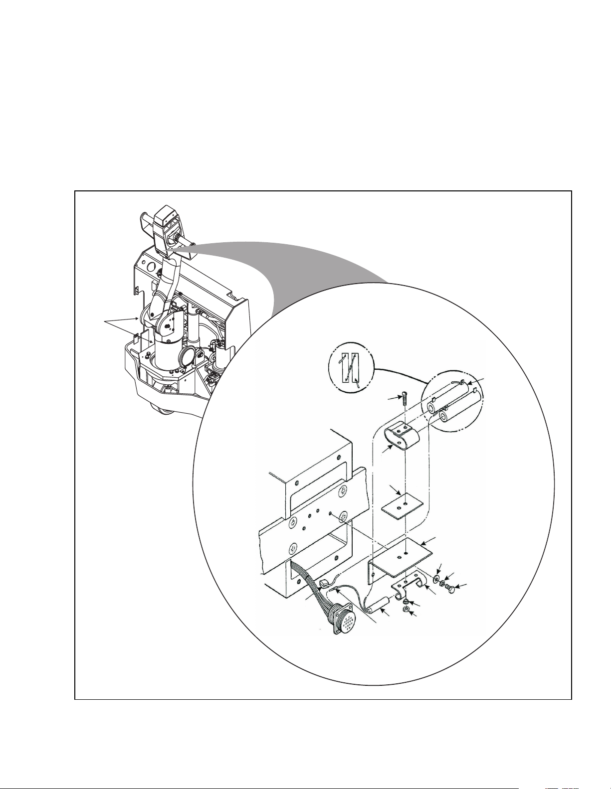
Section 5
OPTIONS
5-1. COLD CONDITIONING PACKAGE.
Continuous operation of the PPT lift trucks at
temperatures below 32° F (freezing) in applications
such as meat lockers and freezers, requires the
changing of oils and grease, and modification of the
16
control head and deadman switch as shown in Figure
5-1. For intermittent operation under 32° F, the oils and
grease need not be changed. Refer to the wiring
diagram to help ensure proper connections.
2
3
4
5
15
13
14
Figure 5-1. Cold Conditioning Package
12
11
6
7
8
9
10
I-7060
PPT0104-901336 5-1
Page 50

NOTES:
5-2 PPT0104-901336
Page 51

6-1. TROUBLESHOOTING CHART
MALFUNCTION PROBABLE CAUSE CORRECTIVE ACTION
Section 6
TROUBLESHOOTING
Truck will not run, lift system does
not operate.
Truck does not run forward or
reverse. All other functions
operate normally.
Truck runs forward but not in
reverse.
Truck runs in reverse but not in
forward.
Truck runs forward and in reverse
at lower speeds; will not run at
high speed.
Truck does not slow with brake, or
brake does not engage
Oil sprays or flows from lift
cylinder.
a. 120 AMP fuse blown Check fuse Replace if necessary
b. Battery dead or disconnected. Check battery and quick disconnect
(Section 4-7.1)
c. Defective wiring. Check for open circuit and repair as
required.
d. Key switch, if equipped,
defective.
a. Check all wiring. A loose
connection may be the cause of
malfunction.
b. Defective Deadman/brake
switch.
c. Switch in control head broken. Check and replace switch if defective.
d. Transistor control fault may need
to be reset.
Defective switch in control head, or
defective contactor.
Defective switch in control head, or
defective contactor.
Defective speed control switch in
control head, or defective by-pass
contactor.
a. Defective brake/deadman
switch.
b. Defective brake solenoid.
Defective seal in lift cylinder. Overhaul lift cylinder and install new
Bypass key switch to determine if bad
Tighten all loose connections before
further troubleshooting
Check and replace switch if defective.
Move control arm up into the neutral
position to reset.
Check for positive dc voltage at wire F2 on reverse contactor. If not present
when steering arm is in operating
position and control lever is in reverse,
reverse switch is defective. If voltage is
present, contactor is defective.
Check for positive dc voltage at wire F1 on forward contactor. If not present
when steering arm is in operating
position and control lever switch is in
forward, forward switch is defective. If
voltage is present, contactor is
defective.
Check resistance at High Speed
switch. If the reading is the same in
either position, the High Speed switch
is bad. Replace switch.Check for
variable resistance at the
potentiometer when direction control is
activated. If not noted, replace
potentiometer.
Check brake/deadman switch for
continuity. If none found when the
control arm is in the brake position,
replace switch.Replace brake
assembly.
seal and wiper ring. See Section 4-8.4
Lift Cylinder Repair.
PPT0104-901336 6-1
Page 52

MALFUNCTION PROBABLE CAUSE CORRECTIVE ACTION
Squealing sounds when lifting
forks.
Lift carriage does not lift to top. Oil level too low. Add oil to reservoir
Weak, slow or uneven action of
hydraulic system.
Forks do not lift, pump motor does
not run.
Forks do not lift, motor runs. Defect in hydraulic system. Check the oil level in the reservoir and
Forks lift, but will not go down. Defect in hydraulic system. Check lowering control switch and
Load will not hold a. Oil bypassing internally between
Forks creep downward under load
when in a raised position.
Steering arm does not return to
the upright position.
Truck moves forward when arm is
pulled down.
Steering arm jerks excessively
starting or stopping the truck.
Drive motor is jerky. Motor commutator damaged. Replace motor.
a. Oil level too low.
b. Lift linkage binding.
a. Defective pump or relief valve.
b. Worn lift cylinder seal.
c. Load larger than capacity.
d. Defective lift motor solenoid.e.
Battery charge low.
a. Battery is dead or disconnected.
b. Defective wiring.
c. Defect in electrical system for
operating pump motor
check valve and adapter body.
b. Worn lift cylinder seal.
Leak in hydraulic system cylinder
seal or lowering valve.
a. Return spring improperly
adjusted.
b. Binding electrical cable.
a. Belly-button switch defective.
b. Short in control head
Drive wheel worn. Replace drive wheel if worn to within 3/
Add oil to reservoir.Apply grease.
Check pressure. Adjust valve.Replace
cylinder seal.Refer to I.D. plate for
capacity.Replace.Charge battery.
Check and recharge if required.Check
and repair as required.Check lift switch
in control head, as well as the solenoid
on the pump motor. Repair or replace.
the oil lines to the lift cylinders, and
repair as required.If normal, check the
hydraulic pump, and relief valve.
Repair, or adjust.
lowering valve; look for blockage in
hydraulic line. Repair/adjust as
required.
Disassemble, clean, and reassemble
Replace worn parts as
required.Replace cylinder seal.
Check lowering solenoid valve and
internal check valve for blockage
preventing valve from closing
completely to block oil. Look for
leaking fitting in hydraulic line. Check
pump for leakage back into reservoir.
Repair or replace as required.
Readjust spring tension.Check and
free the binding item. Verify that the
cable has not been damaged. Repair
or replace as needed.
Check for short, and repair or replace
as necessary.Check wiring and repair
as required.
8 inch of hub.
6-2 PPT0104-901336
Page 53
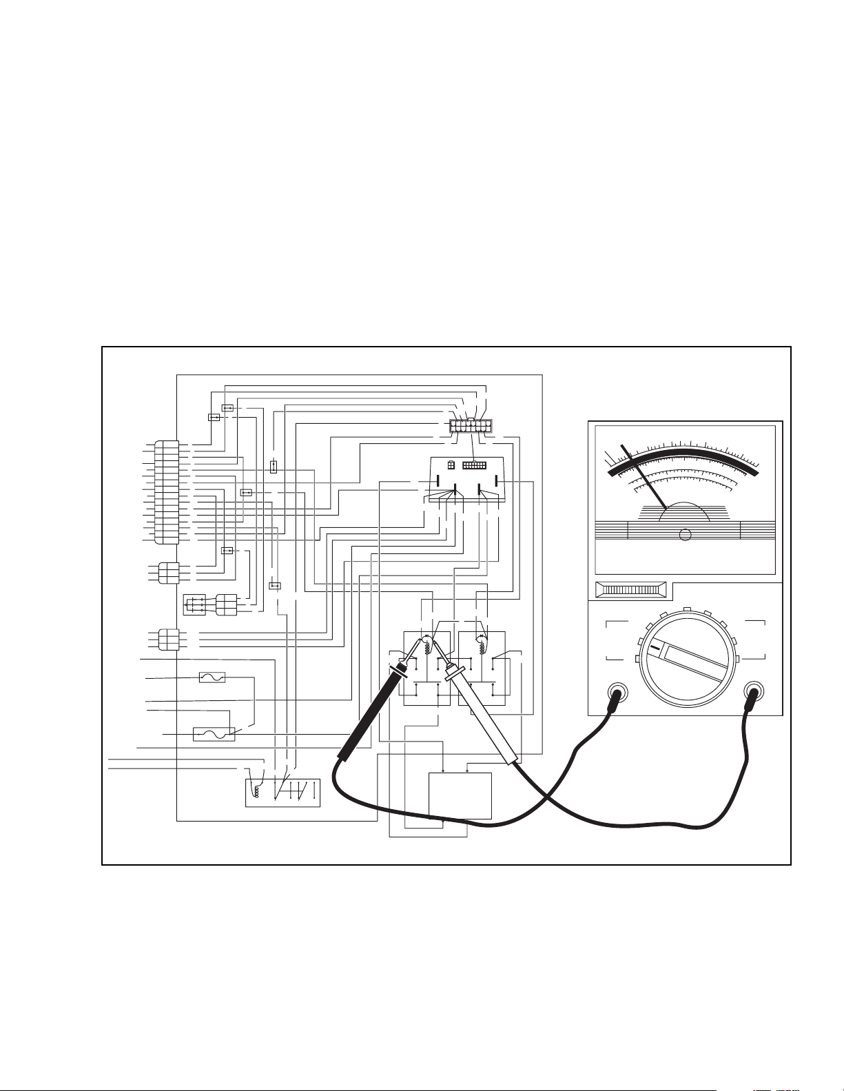
6-2. CONTACTOR TESTING
Make certain battery is in good condition and fully
charged before beginning tests.
6-2.1 Contactor Testing
1. Make certain battery is in good condition and fully
charged before beginning tests.
2. Elevate rear (drive wheel) of truck
3. Reconnect the battery.
4. Place the VOM test meter on the 50V scale and
connect the test probes to the (+) and (-) coil
connections of the suspect contactor (Figure 6-1).
SOLID STATE CONTROL
AND CONTACTOR PANEL
2
1
1
1
1
2
2
4
5
6
7
8
9
10
11
12
3
3
15
16
9
8
6
NEG
NEG
POS
3
4
5
6
7
8
9
10
11
12
13
14
15
16
1
2
3
3
2
1
2
3
4
5
6
7
8
9
10
11
12
3
3
15
16
9
8
6
DIODE ASSY
NEG
NEG
POS
15 AMP
5
A1
5
8
10
3
3
8
1
2
2
1
3
12
16
13
-
F2
NOTE: Testing of the reverse contactor is shown
in Figure 6-1.
5. If the truck is equipped with a keyswitch, turn it on
and place the steering control in the run position
(brake off) and depress the speed control,
6. Voltage should read 24 volts, as applicable. It
voltage does not read 24 volts the problem is in the
switches or wiring leading to the contactor unit.
(See Section 6-6.2 for switch testing.) If 24 volts is
present, the problem is in the contactor unit, and
the contactor must be disassembled and detective
parts replaced.
2
1
4
5
15
16
1315
1112
14
3
8
237
11
7
M-
NEG
NEG
NEG
5
+
13
14
16
9
1
8
A2
B+
B-
100
10
20
50
0
POS
POS
NEG
POS
3
4
5
6
2
1
10
5
15
OHMS Adj
OFF
14
5
5
-
+
F1
D
C
V
RX1Q
1000
150
15
150mA DC
1000
AC 15V
150
0
A
C
V
1000V
AC/DC
150mA DC
MAX
NEG
POS
120 AMP
WHITE
BLACK
3
19
A
AC CHARGING RELAY
500V
REV
3
20
3
3
96
7
34
1
B
NONONC NC
FWD
A2
F1
A1
DRIVE
MOTOR
A2
F2
MAX
I-7039
Figure 6-1. Contactor Testing
6-2.2 Switch Testing.
1. Disconnect the battery
3. Connect the meter test probes to the common #5
(#10 for push button switches) and the suspect
switch lead at the terminal connector.
2. Set the VOM test meter on the RX1 scale.
NOTE: #2 switch lead for the reverse switch is
shown in Figure 6-2.
PPT0104-901336 6-3
Page 54
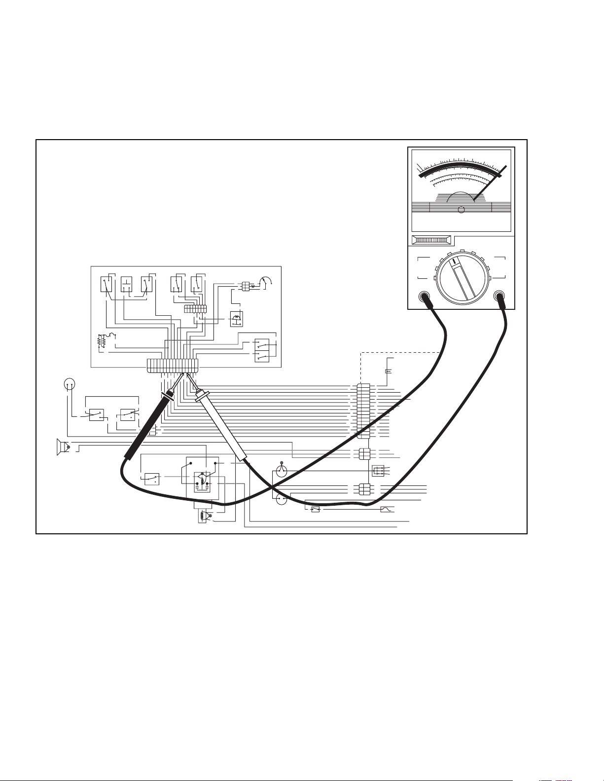
4. If the truck is equipped with a keyswitch, turn it on,
lower the control handle to the driving position and
depress the suspect switch.
5. Resistance should read zero ohms or a small
amount of ohms.
REVERSING
SLOW REV
LOWER
N.C.
N.O.
9
COM
10
10
11
12
13
14
15
16
1110987
12
3
3
3
2
15
15
1
N.C.
8
COM
8
N.O.
LIFT LIMIT
SWITCH
COM
COM
7
3
N.C.
N.C.
N.O.
N.O.
4
6
12
1
8
36547
2
6
12
3
7
4
7
8
9
1
2
3
4
5
6
1
3
654
2
PUMP MOTOR
POS
NEG
NEG
8
POS
PUMP MOTOR
SOLENOID
9
RMT LWR
VALVE
9
SOLENOID
5K SPEED CONTROL
POTENTIOMETER
3
11
11
2
6
1.2K
1
12
12
12
2.7K
12
HIGH SPEED
LIMIT SWITCH
REVERSE
N.O.
2
COM
N.C.
N.O.
1
COM
N.C.
FORWARD
NEG
HORN
ELECTRIC
BRAKE
LIFT
HORN
N.C.
N.O.
8
COM
6
10
10
COLD
10
CONDITIONING
12
CONTROL HEAD
+
-
16
CREEP
SWITCH
3
COM
3
6
NEG
DEADMAN
3
SWITCH
N.C.
N.O.
N.C.
COM
3
N.O.
3
15
33
6. If resistance is present (10 ohms or more), the
switch or wiring leading to the connector is
defective and must be repaired or replaced.
3
4
5
2
5
-
+
HOUR
METER
-
+
DISCHARGE
INDICATOR
33
KEYSWITCH
1
2
4
5
6
7
8
9
10
11
12
3
3
15
16
9
8
6
NEG
NEG
POS
SOLID STATECONTROL
AND CONTACTOR PANEL
1
1
2
2
3
3
4
4
5
5
6
6
7
7
8
8
9
9
10
10
11
11
12
12
13
3
14
3
15
15
16
16
9
1
8
2
6
3
DIODE ASSY
NEG
3
NEG
2
1
POS
15AMP
6
10
100
20
50
5
0
RX1Q
1000
D
C
150
V
15
500V
MAX
10
OHMS Adj
OFF
15
150mA DC
150mADC
1
1000
1000V
AC/DC
MAX
AC 15V
150
0
A
C
V
I-7040
Figure 6-2. Switch Testing
6-4 PPT0104-901336
Page 55
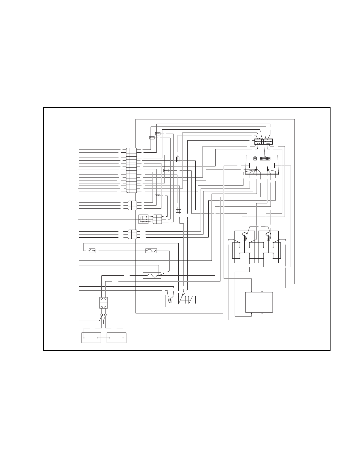
6-3. TRANSISTOR CONTROLLER TROUBLE-
SHOOTING
The basic Big Joe Transistor Controlled Electrical
System is shown in schematic form in Figure 6-3. Refer
to the wiring diagrams included in Chapter 4 for
complete wiring diagram for this truck. Refer to these
diagrams and the schematic for tracing of electrical
circuits during troubleshooting and testing procedures.
SOLID STATE CONTROL
AND CONTACTOR PANEL
2
1
1
1
1
2
33
KEYSWITCH
RED
BLACK
-
+
BATTERY
CONNECTOR
-
+
STANDOFFS
NEGPOS
NEG
2
4
6
8
10
12
3
16
NEG
NEG
POS
5
7
9
11
3
15
9
8
6
POS
3
4
5
6
7
8
9
10
11
12
13
14
15
16
1
2
3
DIODE ASSY
3
2
1
2
3
4
5
6
7
8
9
10
11
12
3
3
15
16
9
8
6
NEG
NEG
POS
15 AMP
120 AMP
WHITE
BLACK
8
3
8
1
2
2
1
3
19
A
AC CHARGING RELAY
10
20
1
B
2
1
4
5
15
16
14
1315
1112
3
8
237
16
8
B-
NEG
5
B+
-
F1
F2
14
9
1
POS
POS
14
5
FWD
DRIVE
MOTOR
13
A2
POS
+
F1
11
5
5
3
3
F2
3
3
3
96
7
34
NONONC NC
7
M-
A1
12
16
NEG
NEG
NEG
5
13
-
+
REV
A2
A1
A2
+
-
BATTERIES
-
+
I-7041
Figure 6-3. Transistor Controller Schematic
PPT0104-901336 6-5
Page 56
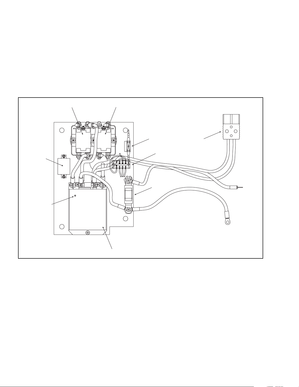
6-3.1 Circuit Operation
14
MAX
15AMP
While operation of the transistorized control system is
transparent to the operator, it is helpful to understand
the operating principles and features of the transistor
controller when troubleshooting trucks equipped with
this controller. The controller (2, Figure 6-4) is mounted
on the contactor electrical panel, installed within the
motor compartment of the lift truck. Figure 6-6 identifies
the contacts of a typical controller.
1
POS
4
1
1
FWDREV
MAX 15AMP
4
5
6
3
NEG
POS
POS
A2
NEG
3
120 AMP
MAXIMUM
7
NEG
8
2
I-7041
Figure 6-4. Contactor Panel Parts
1. Smooth Stepless Operation.
The Big Joe custom transistor controller allows
superior control of the vehicle's drive motor speed.
The amount of current delivered to the motor is set
by varying the 'on" time (duty cycle) of the controllers transistors. This technique, called "pulse width
modulation" (PWM), permits silent, stepless operation.
2. Current Multiplication.
During acceleration and during reduced speed
operation, the controller allows more current to flow
into the motor than flows out of the battery. The
controller acts like a DC transformer, taking in low
current and high voltage (the full battery voltage)
and putting out high current and low voltage. The
battery only has to supply a fraction of the current
that would be required by a conventional controller
(in which the battery and motor current are always
equal). The current multiplication feature gives
vehicles using these controllers greater driving
range per battery charge.
3. Acceleration Limiting.
A built-in acceleration limiting circuit maintains a
maximum rate of power increase to the motor. If full
throttle is applied at start-up, the acceleration ramp
setting determines how quickly the output of the
controller increases. When full throttle is applied,
the standard controller setting requires approxi-
6-6 PPT0104-901336
Page 57

mately one second to reach full output. This feature
contributes to smooth, even starts. (See adjustment instructions to adjust acceleration rate setting.)
4. Current Limiting.
The transistor controllers limit the motor current to
a preset maximum. This feature protects the controller from damage that might result if the current
were limited only by the motor demand. The current limit feature also protects the rest of the system. By eliminating high current surges during
vehicle acceleration, the stresses on the motor and
batteries are reduced and their efficiency and service life are improved. Because of the smoother
operation, there is less wear and tear on the vehicle drive train.
The maximum motor current can be factory-set to a
lower value than the standard maximum if
requested. For further flexibility, the current limit
setting on some models is field-adjustable. (See
adjustment instructions.)
5. Plugging.
A form of electrical braking, called plugging, can be
used to slow the vehicle. When the motor is
reversed with the accelerator advanced (i.e.. when
the vehicle is moving forward, the direction control
is moved to the REVERSE position), the armature
acts as a generator. Current from the armature
flows through a plug diode in the controller. The
controller regulates the current in the motor field
winding to give an appropriate level of plugging
torque. The vehicle slows smoothly to a stop, and
then automatically accelerates in the other direction. A 1 kHz tone will be heard during plugging.
The maximum plugging current is factory set per
customer requirements, and is also field adjustable
(see adjustment instructions).
6. Under-voltage Protection.
The control circuitry requires a minimum battery
voltage to function properly. The controller is
designed so its output is gradually reduced if the
battery voltage falls below a certain level. The cutoff voltage is listed in the specifications (see Table
6-1). Reducing the output to the motor allows the
battery voltage to recover, and an equilibrium is
established in which the battery supplies as much
current as it can, without falling below the minimum
voltage cutoff.
7. Over-voltage Protection.
As with the under-voltage protection, the controller
has a means of preventing operation when battery
voltages reach an "over-voltage" situation, a condi-
tion where battery voltages are too high for proper
functioning. Excess voltage can occur from an
unregulated battery charger or from improper or
faulty wiring.
Table 6-1. Controller Specifications.
Big Joe Model 90 /200-02
Input Voltage 24
Current Limit 250 Amps*
Rating:
1 Minute 250 Amps
2 Minute 200 Amps
5 Minutes 150 Amps
1 Hour 100 Amps
Under-voltage Cutout 16 V
Max F/R current 2 Amps
Operating Frequency 15 kHz
*60 second rating.
8. Thermal Protection.
Because of their design, the controllers barely get
warm to the touch in normal operation. However,
overheating can occur if the controller is undersized for its application or becomes overloaded. If
the internal temperature of the controller exceeds
165° F (74° C) the current limit is automatically
reduced. The current limit continues to drop
steadily until at 200° F (94° C) it is reduced to zero
and the truck will not function. This feature allows
the vehicle to be operated at a reduced performance level in order to permit maneuvering out of
the way and stopping in a safe location. After the
controller cools down, full current limit and performance return automatically.
Although this action is not damaging to the controller, it does suggest a mismatch. If thermal cutback
occurs often in normal vehicle operation, the controller is probably undersized for the application,
and a higher current model should be used. The
controller shifts frequency during an "over temperature" condition from its normal 15 kHz to 1 kHz,
providing an audible tone alerting the operator to
the over temperature condition.
The controller is also protected from under temperature operation. Should the controllers internal
temperature fall below -13° F (-25° C) (for example
being parked overnight in an icehouse), the current
limit will be 1/3 the maximum. Once the controller
warms above 77° F (25° C), full current limit and
performance return automatically.
PPT0104-901336 6-7
Page 58

9. Accelerator Fault Protection (Runaway Protection).
11. Hand Held Programmer (Optional)
To prevent uncontrolled operation, the controller
shuts off the motor output in the event a short circuit fault in the accelerator or its wiring is detected.
The throttle configuration is a 2-wire potentiometer
ranging from 5000 ohms for full off to 0 ohms for
full on. The controller returns to normal operation
when the fault (e.g., accelerator wiring, broken
connectors, potentiometers that fail or are set to
start at 0) has been corrected.
10. Controller Fault Detection.
An internal micro-controller automatically maintains
surveillance over the functioning of the controller.
When a fault is detected, the appropriate fault code
is signaled via the LED, externally visible on the
side of controller (See 8, Figure 6-4 for LED location on controller). The diagnostic codes flashed by
the LED are listed in Table 6-4.
If the fault is critical, the controller is automatically
disabled. Faults can be caused internally (e.g..
shorted transistors) or externally (e.g., wrench or
hardware dropped across controller terminals).
While disabled, the controller's direction contactor
output and internal logic are both off.
Faults are detected by monitoring the controllers
M-output. If the M-output remains low for more
than 20 ms, a fault is detected. Fault protection is
disabled for throttle demand greater than 80%.
To recover from a fault, the F/R switch must be
turned off and back on again. If the fault has been
corrected, the controller will turn back on.
The automatic fault detection system includes:
• Contactor coil open / shorted driver (F/R and
shunt contractor)
• Contactor driver over-current / contactor coil
short
• Contactor welded
• Emergency reverse circuit check
• M- output fault
• Memory checks upon start-up
• Over-voltage cutback
• Power supply out of range (internal)
• Throttle fault
• Under-voltage cutback
• Watchdog (external and internal)
• Watchdog (internal)
A hand held programmer is available that is
designed specifically for use with the controller. It
serves dual functions of reading diagnostic data
provided by the controller and adjusting certain
performance values of the controller. The programmer (Part Number 005472-02) is available
through your Big Joe dealer. If you require dealer
location information, contact Big Joe Manufacturing Co. phone number 847-675-8700.
12. Fault Recording.
Fault events are recorded in the controller's memory. However, multiple occurrences of the same
fault are recorded as one occurrence
The fault event list can be loaded into the programmer for readout. The Special Diagnostics mode
provides access to the controller's diagnostic history file. The history file contains the entire fault
event list created since the diagnostic history file
was last cleared. The standard Diagnostics mode
provides information about only the currently active
faults.
13. Fault Recovery (including recovery from disable).
Almost all faults require a cycling of the KSl (Key
Switch Input) or brake input to reset the controller
and enable operation. The only exceptions are
shown in Table 6-2.
Table 6-2. Fault Recovery Exceptions.
FAULT RECOVERY
Anti-tie down Release and re-select Mode 1
Contactor overcurrent
Emergency
reverse
HPD (High
Pedal Disable)
Over-voltage When battery voltage drops below
SRO When proper sequence is
Thermal cutback When temperature comes within
Throttle fault Clears when condition gone
Under-voltage When battery voltage rises above
When condition clears
Belly Button switch re-applied or
brake cycled
Lower throttle to below HPD
threshold
over-voltage setting
followed
range
under-voltage level
6-8 PPT0104-901336
Page 59

14. Emergency Reverse: Enhanced Plugging Current.
Emergency reverse (or "belly button") switches are
mounted on the handles of walkie vehicles. The
emergency reverse switch is wired to the controller
and other vehicle electronics in such a way that if
the button is pressed against the operator by the
advancing vehicle, the controller enables
enhanced plugging current to slow the vehicle and
reverse its direction. After the button is released,
normal controller operation is not resumed until
neutral (no movement) is selected or until the
brake is cycled (brake, then release). However,
repeatedly pressing the belly button will reactive
the emergency reverse function.
15. Arcless F/R Switching.
Each time the F/R switch passes through neutral,
the controller's output is rapidly turned off (even if
the throttle is held on) so that all motor current has
stopped by the time the direction contactor drops
out. Controller output always starts at zero and
increases smoothly at the set acceleration rate
each time a new direction is selected. Bypass contactor operation is also arcless, when interrupting
currents less than the controller's current limit.
16. High Pedal Disable (HPD)
When the controller Key Switch Input (KSI) is
turned on, it will sense a "high" (advanced accelerator) situation and will inhibit the output until the
accelerator is released and reapplied. By preventing the unit KSI from being turned on with the throttle depressed, this safety feature (also called
Neutral Start) required the truck to start smoothly
from zero throttle when the battery is plugged in. It
also protects against sudden starts caused when
problems in the throttle linkage (e.g., bent parts,
broken return spring) give a partial or full throttle
signal to the controller, even with the accelerator
released, when the battery is plugged in.
6-3.2 GENERAL SYSTEM CHECKOUT.
Carefully complete the following checkout procedure. If
you find a problem during the checkout, refer to
Section 5 for further information.
The checkout can be conducted with or without the
handheld programmer. However, the checkout
procedure is easier with a programmer. To evaluate the
system without a programmer, observe the LED and
note the flashing pattern and refer to Table 6-4 for the
code description.
CAUTION
• Put the vehicle up on blocks to get the drive
wheel off the ground before beginning these
tests.
• Turn the keyswitch off and make sure that
the brake is applied (brake switch open), the
throttle is in neutral, and the forward/reverse
switches are open.
• Do not stand, or allow anyone else to stand,
directly in front of or behind the vehicle
during the tests.
1. If a programmer is available, connect it to the
programmer connector (6, Figure 6-7) on the
controller.
2. Turn the lift truck key switch to the ON position.
The programmer should "power up" with an initial
display (2, Figure 6-5), and the controllers Status
LED should begin steadily blinking a single flash. If
neither happens, check for continuity in the key
switch circuit and controller ground.
3. If you are using a programmer, put it into the
diagnostic mode by pressing the "Menu Navigation
Key" (1, Figure 6-5). Using the Navigation key,
select the Faults menu. Display the Faults menu by
pressing the Right side of the Navigation key.
Press the Right side of the Navigation key again to
display the list of System Faults. The display
should indicate "No Known Faults."
Release the brake by pulling down the control arm
into the operating position. The controllers LED
should continue blinking a single flash and the programmer should continue to indicate no faults. If
there is a problem, the LED will flash a diagnostic
code and the programmer will display a diagnostic
message. If you are conducting the checkout without a programmer, look up the LED diagnostic
code in Table 6-4.
When the problem has been corrected, it may be
necessary to cycle the brake in order to clear the fault
code.
PPT0104-901336 6-9
Page 60
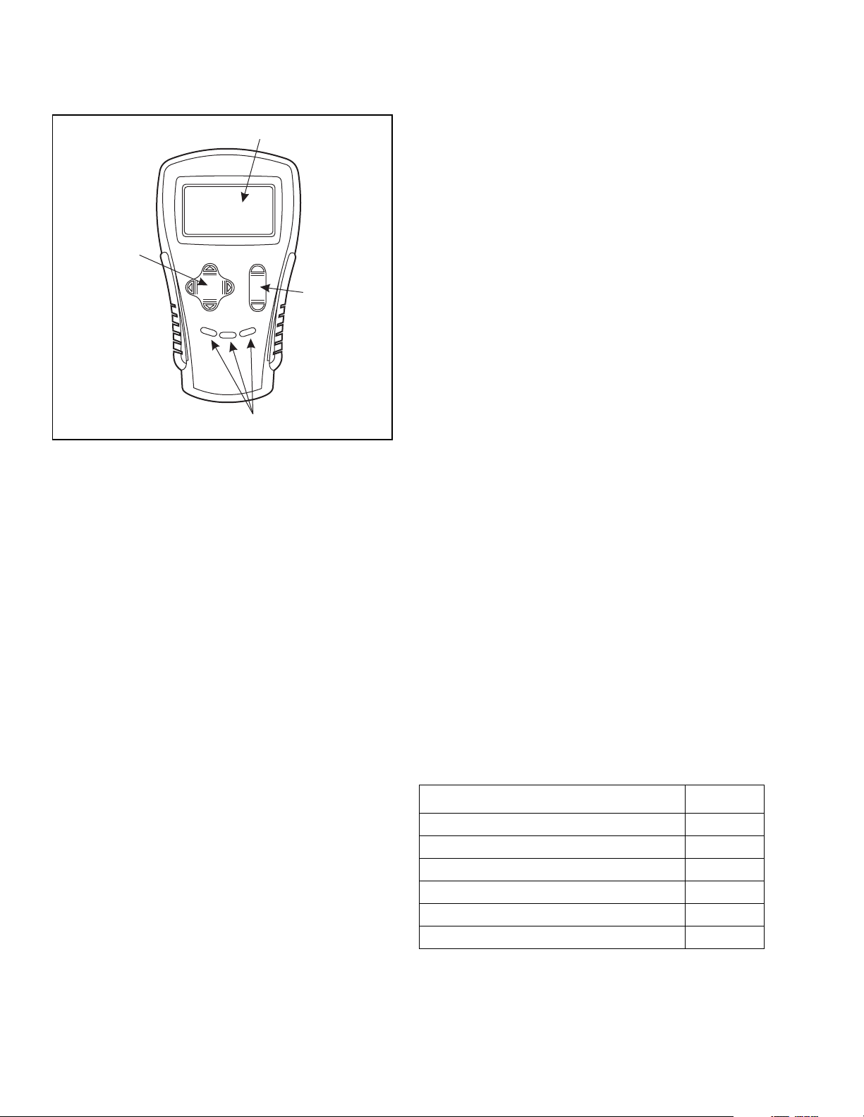
2
1
+
3
-
4
I-7045
Figure 6-5. Hand Held Programmer
4. With the brake released, select a direction and
operate the throttle. The motor should begin to turn
in the selected direction. If it does not, verify the
wiring to the forward/reverse switches, forward/
reverse contactors and motor. The motor should
run proportionally faster with increasing throttle. If
not, refer to Section 5.
5. If you are using a programmer, put it into the test
mode by using the Navigation key (1) to select the
"Monitor" menu. Select the Monitor mode by
pressing the "Right" arrow on the Navigation key.
Press the Navigation key "Down" arrow to scroll
down to observe the status of the forward, reverse,
brake, emergency reverse, and mode switches.
Cycle each switch in turn, observing the
programmer. Each input should show the correct
state on the programmer.
6. Check the controller's fault detection circuitry as
described in Section 6-3.1, Step 10.
7. Take the vehicle off the blocks and drive it in a
clear area. It should have smooth acceleration and
good top speed.
8. Test the plug braking of the vehicle. The vehicle
should smoothly slow to a stop and reverse
direction, with the audible plugging tone.
9. Verify that all options, such as high pedal disable
(HPD), static return to off (SRO), and anti-tie-down,
are as desired.
10. Check to see whether the emergency reverse
(belly button) feature is working correctly. Verify
that the circuit is operational by momentarily
disconnecting one of the emergency reverse wires.
The vehicle should be disabled and a fault
indicated.
6-3.3 ADJUSTMENT
To change a parameter using the programmer, use the
Navigation key (1) to select the "PROGRAM" menu.
Press the Right key to display a listing of program
settings. Scroll down the Program Listing until the
desired parameter is highlighted on the display. Press
the Right key to display the settings for the item
selected. Press the Increase/Decrease key ("+" or "-")
(3, Figure 6-5) until the desired value setting is
reached. The parameter is now set at the desired
value. All programming occurs in real time. That means
the parameter can be changed while the vehicle is in
operation.
Some parameters are dependant on other parameters.
When the programmer is being used to adjust a
parameter and a limit is reached, the display will stop
changing.
NOTE: Changing the value of the related parameter
may allow the original parameter to be
adjusted further.
Table 6-3. Adjustment Settings
Function Setting
Creep Speed 7
Mode 1- Plugging Current Limit 80A
Mode 1 - Acceleration Rate 1.0s
Mode 2 -Plugging Current Limit 80A
M ode 2 - Acceleration rate 1.0
Mode 2 - Maximum Speed 85%
6-10 PPT0104-901336
Page 61

6-4. DIAGNOSTICS.
The motor controller provides diagnostics information
to assist in troubleshooting drive system problems. The
diagnostics information can be obtained in two ways:
• Reading the appropriate display on the programmer
• Observing the fault codes issued by the Status
LED. The Status LED is located on the side of the
controller. See 8, Figure 6-4 for location of the LED
on the controller.
During normal operation with no faults present, the
Status LED flashes a single flash at approximately 1
flash/second. If the controller detects a fault, a 2-digit
fault identification code is flashed continuously until the
fault is corrected. For example, three flashes followed
Table 6-4. LED Codes
LED Code Explanation
LED Off Not illuminated No power or defective controller
Solid On Always on Defective controller
Single Flash 0 Controller operational, no faults
1 - 2 0 00 Hardware fail-safe error
1 - 3 0 000 M- fault or motor output short
1 - 4 0 0000 Sequencing fault (SRO)
2 - 1 00 0 5k W-0 or throttle wiper input fault
2 - 2 00 00 Emergency reverse circuit check fault (BB wiring)
2 - 3 00 000 High-pedal-disable fault (HPD)
2 - 4 00 0000 Throttle pot low open or shorted to B+ or B-
3 - 1 000 0 Contactor or shunt driver over current
3 - 2 000 00 Welded direction contactor
3 - 3 000 000 Not used - reserved for future use
4 - 1 0000 0 Low battery voltage
4 - 2 0000 00 Overvoltage
4 - 3 0000 000 Thermal cutback
4 - 4 0000 0000 Not used - reserved for future use
by two flashes is code "3,2" appears in the LED code
table as:
000 00 000 00 000 00
(3,2) (3,2) (3,2)
The codes are listed in Table 6-4. The "0" 's in Table 64 indicate an illuminated LED. For suggestions about
possible causes of the various faults, refer to 6-1
Troubleshooting Chart at the beginning of this section.
Operational faults, such as an over-temperature
situation, are cleared as soon as the operation is
brought within range. Non-operational faults, such as a
throttle fault, usually requires the brake or key switch to
be cycled after the problem is remedied.
NOTE: Only one fault is indicated at a time and faults are not presented in the sequence shown in Table 6-4.
PPT0104-901336 6-11
Page 62

6-4.1 Programmer Diagnostics
With a programmer, diagnostics and troubleshooting is
more direct than with the LED alone. The programmer
presents complete diagnostic information in plain
language - no code to decipher. Faults are displayed in
the Diagnostic Menu, and the status of the controller
inputs/outputs is displayed in the Test Menu.
The following 4-step process is generally used for
diagnosing and troubleshooting an inoperative vehicle
using the programmer:
1. Visually inspect the vehicle for obvious problems:
2. Diagnose the problem:
3. Test the circuitry with the programmer:
4. Correct the problem.
Repeat the last three steps as necessary until the
vehicle is operational.
Refer to the Troubleshooting Chart (Section 6-1.) for
suggestions covering a wide range of possible faults.
6-4.2 Diagnostic History
The handheld programmer can be used to access the
controller's diagnostic history file. When the
programmer is connected to the unit, the error log file is
automatically uploaded into the handheld programmer.
To see the present status of the unit, use the Menu
Navigation Key (1, Figure 6-5) to select:
Faults->System Faults.
To access this log, use the Menu Navigation Key to
select:
Faults->Fault History
The faults are shown as a code and descriptive text. If
there are multiple faults, you have to scroll through the
list using the Up and Down Buttons on the Menu
Navigation Key
The faults may be intermittent faults, faults caused by
loose wires, or faults caused by operator errors. Faults
such as contactor faults may be the result of loose
wires: contactor wiring should be carefully checked out.
Faults such as HPD or over-temperature may be
caused by operator habits or by overloading.
After a problem has been diagnosed and corrected,
clearing the diagnostic history file is recommended.
This allows the controller to accumulate a new file of
faults. By checking the new diagnostic history file at a
later date, you can quickly determine whether the
problem has been completely fixed.
To clear the diagnostic history file, select:
Faults->Clear Fault History.
You will be asked to confirm your actions. Use the
"plus" arrow (+) for yes to clear the menu and the
"minus" arrow (-) (3, Figure 6-5) to cancel your
selection and not clear the Fault History.
6-4.3 Test the Fault Detection Circuitry
1. Put the vehicle up on blocks to get the drive wheel
off the ground.
2. Disconnect the battery and make sure the keyswitch is in the "OFF" position.
3. Using an inline fuse holder fitted with a 10 amp
fuse and alligator clips, connect the controller's M
and B- terminals. See 3, 4, Figure 6-7.
4. Reconnect the battery and turn the key switch to
the "ON" position. Release the brake and apply the
throttle. The motor should not operate and the
direction contactors should not pull in.
5. Leave the key switch on and remove the in-line
fuse wire. The vehicle status should continue to
remain off.
6. Cycle the key switch off and on. Release the brake
and apply the throttle. The vehicle should now
operate normally.
6-5. MAINTENANCE
There are no user-serviceable parts inside the
controller. No attempt should be made to open the
controller. Opening the controller may damage it and
will void the warranty
The transistor controller is programmed at the factory
specifically for the truck on which it is equipped. It is
important to replace the controller with the correct
preprogrammed performance settings to make sure
that the truck operates properly. See the Illustrated
Parts List for the preprogrammed controller part
number.
It is recommended that the controller exterior be
cleaned periodically and if a handheld programmer is
available, this periodic cleaning provides a good
opportunity to check the controller's diagnostic history
file. It is also recommended that the controller's fault
detection circuitry be checked whenever the vehicle is
serviced.
6-12 PPT0104-901336
Page 63
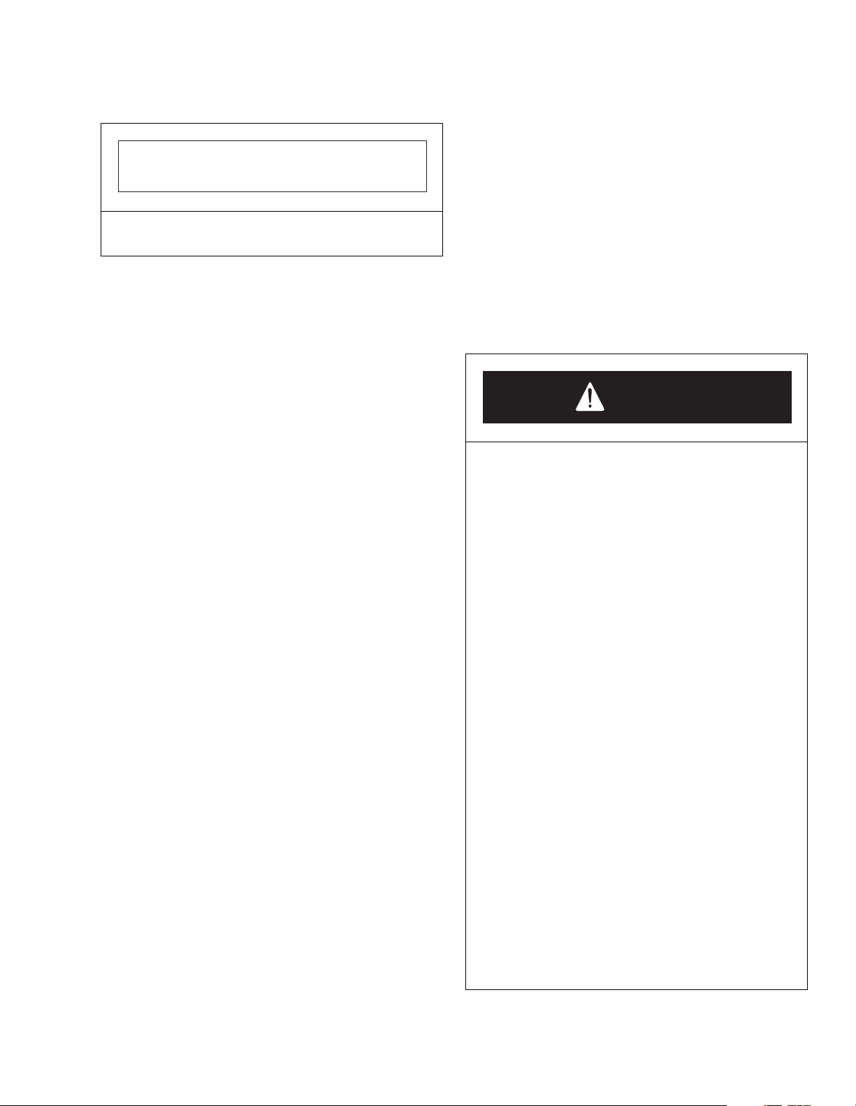
6-5.1 Cleaning
IMPORTANT
If the unit is being operated in an extremely dusty
location, more frequent cleaning is recommended.
6-6. TROUBLESHOOTING
The following procedures are to fix vehicles that will not
operate properly. Refer to the basic wiring schematic
(Figure 6-3) when conducting these tests. Make sure
the controller is hooked up as shown in Figure 6-4.
Refer to the wiring diagram and schematic for your
vehicle. These tests require a general purpose volt
ohmmeter. You can use either a conventional "VOM" or
an inexpensive digital voltmeter.
1. Remove power by disconnecting the battery
2. Discharge the capacitors in the controller by
connecting a load (such as a contactor coil or a
horn) across the controllers B+ and B- terminals.
3. Remove any dirt or corrosion from the bus bar
areas on both the Forward and Reverse
contactors. The controller should be wiped clean
with a moist rag. Allow it to dry completely before
reconnecting the battery.
4. Make sure the connections to all of the Forward
and Reverse contactor bus bars are tight. Use two
well insulated wrenches for this task in order to
avoid stressing the bus bars.
6-5.2 Transistor Control Electrical Panel
Maintenance
1. Panel Removal
a. Disconnect the battery.
b. Remove the motor compartment cover per
instructions in Section 4 of this manual.
c. Refer to Figure 6-4 and tag and disconnect all
electrical wires and cables from the transistor
control electrical contactor panel.
d. Remove two nuts and lock washers to release
and remove the electrical panel.
2. Panel Disassembly and Reassembly
a. Refer to Figure 6-4 for identity of components
of the electrical panel and as required, remove
defective components.
b. Upon reassembly of the electrical panel,
inspect each connection to make sure that a
good positive contact is made at all wire and
cable connections.
3. Panel Installation
a. Install the electrical panel assembly in reverse
of instructions for removal.
In general, when a problem has been isolated as a fault
within the controller, the controller must be replaced. If
the source of the problem has not been determined or
is suspected to be within other truck systems and not
the controller, proceed as directed.
DANGER
• Working on electric vehicles you must
protect yourself against runaways, high
current arcs, and out-gassing from lead acid
batteries:
• Runaways
• Some fault conditions could cause the
vehicle to run out of control. We suggest
that you jack up the vehicle and get the
drive wheels off the ground before
attempting these procedures or any other
work on the motor control circuitry.
• High current arcs
• Electric vehicle batteries can supply very
high power for short times. If they are
accidentally short circuited, arcs can
occur. Always open the battery circuit
(disconnect battery) before doing work
on the motor control circuit. Wear safety
glasses and use properly insulated
wrenches to prevent accidental shorts.
DO NOT wear jewelry (rings, bracelets,
etc) while working on the electrical
controls of any lift truck.
• Lead acid batteries
• Charging or discharging batteries
generates hydrogen gas, which can build
up in and around the batteries. Always
follow the battery manufacturers
recommendations when working around
batteries. Wear safety glasses.
PPT0104-901336 6-13
Page 64
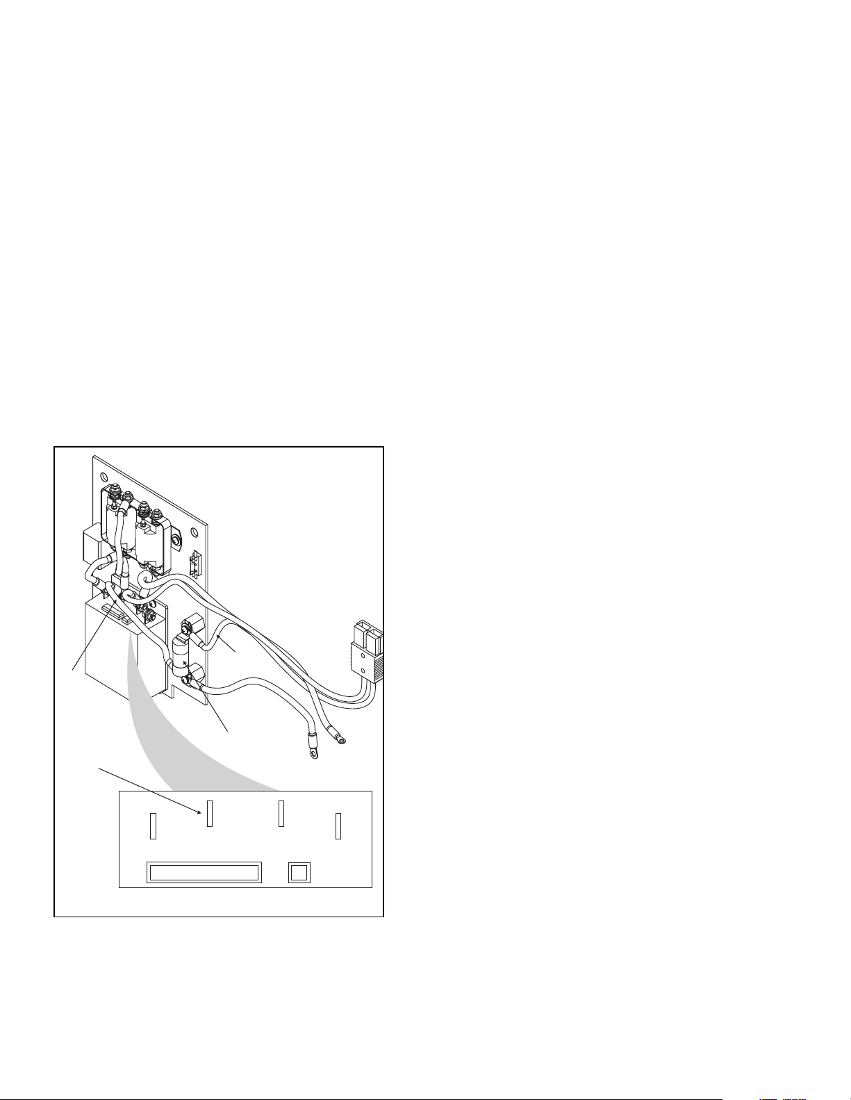
6-6.1 Check for Power to the Controller
1. Leave the keyswitch off for these tests (if truck is
so equipped).
2. Verify that battery negative terminal (-) connects to
the "B-" terminal of the controller. Connect
voltmeter negative lead (-) to this point.
3. Connect voltmeter positive lead (+) to the battery
side of the power fuse (2, Figure 6-6). Check for full
battery voltage. If it is not there, the trouble is in the
battery pack or the cables to it.
4. Connect the voltmeter positive lead (+) to the
controller B+ terminal (1, Figure 6-6). You should
read full battery voltage. If this voltage is zero or
close to zero, the trouble is either a bad controller,
a bad power fuse (2), or an incorrectly connected
cable (3, 4). Trace the cable to make sure it is
hooked up properly. If these check out, the
controller is malfunctioning and must be replaced.
4
3
2
1
A2
B+
Figure 6-6. Controller Terminals
B-
Prog
M-
I-7042
6-6.2 Check for Contactor Operation and Key-
switch Input (KSI)
1. If the truck is equipped with a power key, turn the
key to the ON position and move the accelerator in
forward or reverse, until the micro switch operates
(clicks).
2. This should cause the main contactor to operate
with an audible click. Connect the voltmeter across
the contactor coil terminal. You should see full
battery voltage.
3. The controller KSI terminal should also be getting
full battery voltage. Verify this with the voltmeter.
Connect the voltmeter (-) to the controller Bterminal, and the voltmeter (+) to the controller's
KSI terminal, pin 16 (wire 3) on the multi-pin
connector to the controller.
4. If the contactor coil and KSI terminal are not getting
voltage, that's the problem. Use the voltmeter to
find out where it is not getting through. Connect the
voltmeter (-) to the controllers B- terminal and
check the following points with the voltmeter (+)
lead to trace the flow and determine where the
power loss occurs:
a. First, check both sides of the control wiring fuse.
b. Check both sides of the keyswitch (if truck is so
equipped).
c. Check both sides of the accelerator
miscroswitch.
d. Finally, check the contactor coil and controller
KSI.
5. If the contactor coil and KSI are getting voltage,
make sure that the contactor is really working by
connecting the voltmeter across its big terminals.
There should be no measurable voltage drop. If
you see any at all, the contactor is bad.
6-6.3 Check Potentiometer Circuitry
The following procedure applies to the basic
accelerator input configuration for these controllers,
which is a nominal 5000 ohm potentiometer connected
as a two-wire rheostat (0 ohms = full on, 5000 ohms =
full off).
1. With the forks lowered, the keyswitch off, and the
battery disconnected, remove the multi-pin
connector going to the controller. Connect an
ohmmeter to pins 7 + 8 (wires 7 + 11). Lower the
control arm and measure the resistance as you
move the accelerator. The resistance at the limits
should be within these ranges:
Accelerator at Start: 4300 ohms to 4800 ohms
Accelerator at Maximum: 0 ohms to 50 ohms
6-14 PPT0104-901336
Page 65
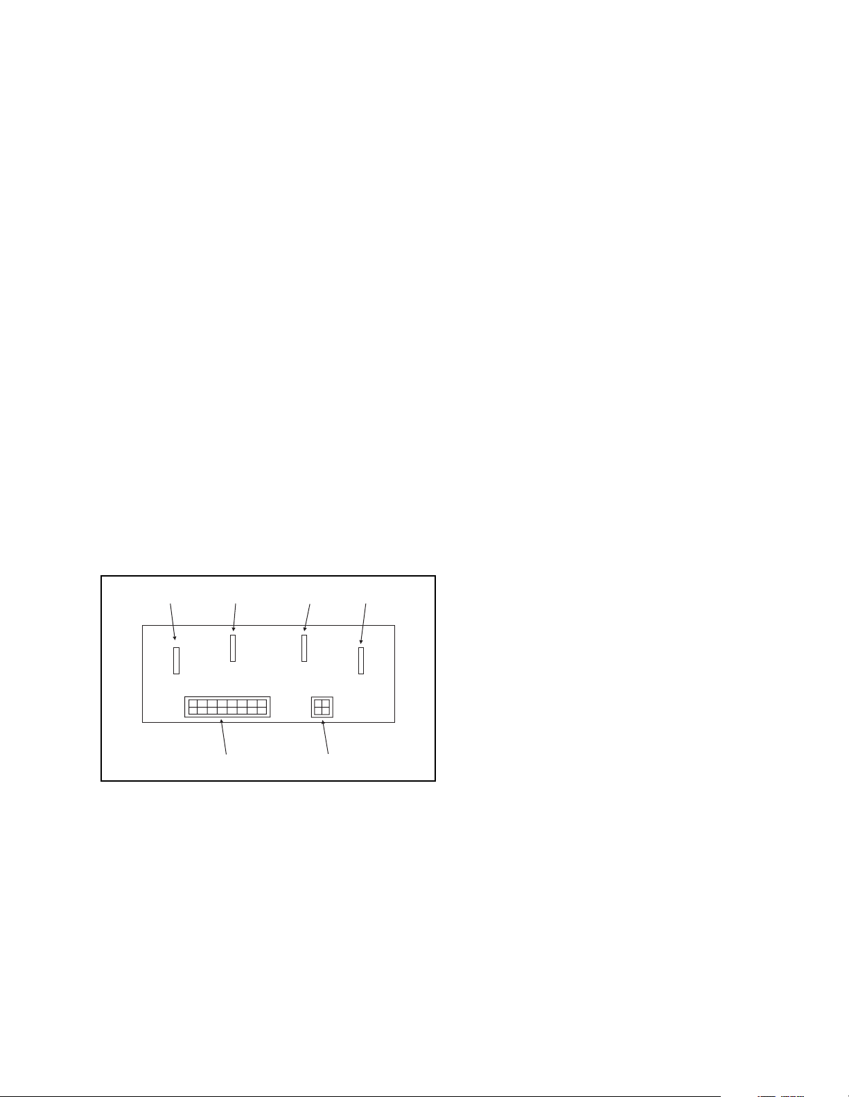
2. If these resistance readings are wrong, it is
because the potentiometer itself is either:
• faulty or out of adjustment,
• the wires to the pot are broken or
misconnected,
• the linkage is not moving the pot shaft through
its proper travel,
• or a switch, resistor, or the relay is defective or
incorrectly wired. (See wiring diagram.)
3. While you have the accelerator wires off the
controller, use an ohmmeter to check for a short
circuit between these wires and the vehicle frame.
You should see a resistance of at least 10,000
ohms. If it is lower than that, inspect the wiring for
damaged insulation or contact with the frame. If
necessary, replace the potentiometer.
4. Reconnect the multi-pin connector to the controller.
6-6.4 Check for controller output
1. Disconnect the wire from the direction contactors
to the F/R contactor output of the controller.
2. Connect the voltmeters positive (+) lead to the
controller's B+ terminal (2, Figure 6-7). Connect
the voltmeter negative (-) lead to the controller's Mterminal (4).
1
A2
Figure 6-7. Controller Terminals
3. Connect the battery, turn on the keyswitch, move
the accelerator in forward, and watch the voltmeter
as you advance the accelerator. The voltmeter
should read zero with the accelerator released,
and should read full battery voltage with the
accelerator at maximum, If it does not, the
controller is bad and must be replaced. If the
voltmeter readings are appropriate, release the
accelerator, turn off the keyswitch, disconnect the
battery, and reconnect the wire to the direction
contactors.
2
B+
3
B-
56
Prog
4
M-
I-7043
4. The next step is to measure the current in the
controller's M- lead. If you have a means of
measuring this high dc current, such as a shut/
meter setup or a clamp-on dc ammeter, use it. If
not, we recommend that you buy an ammeter of
the type that is simply held against the wire being
tested. These are available for a low cost at auto
parts stores. Though the accuracy of these meters
is not great, they are adequate for this test.
5. Connect the battery, turn the key switch on, move
the accelerator in either forward or reverse, and
watch the ammeter while advancing the
accelerator.
6. If you see no current flowing in the M- lead, the
problem is an open circuit in the motor or the wiring
between the motor and the controller. Test the
following:
a. Check the F/R switch.
b. Verify the Reverse contactor. Check to see that
the contactor is operating properly.
c. Check the motor armature and field for opens.
7. If a high current flowing is noted in the M- lead but
the motor does not run, the problem is either a
short in the motor circuit, a miswired motor, or a
short in the controller's internal plug diode. Test the
plug diode as follows:
a. Remove power by opening the battery circuit.
Take the cable off the controller's A2 terminal
(1, Figure 6-7).
b. Use an ohmmeter to check the resistance
between the controllers A2 (1) and B+ (2)
terminals. You are testing the state of a diode
inside the controller, so swap the two leads of
the ohmmeter and look for a low resistance
one way and a much higher one the other way.
If your meter has a diode test function, use that
setting.
c. If you find the diode to be shorted, the
controller is bad and needs to be replaced.
8. Put the A2 cable back on the controller.
9. If the plug diode is OK, there is a short in the motor
circuit. An ordinary ohmmeter will not work to find
the short, because the resistances of the motor
windings are so low. Test the motor separately if it
is suspected of having a shorted winding.
10. Verify all illustrated connections and components
within the truck. See Chapter 4. If all check out and
the source of the problem still has not been found,
replace the controller.
PPT0104-901336 6-15
Page 66

NOTES:
6-16 PPT0104-901336
Page 67
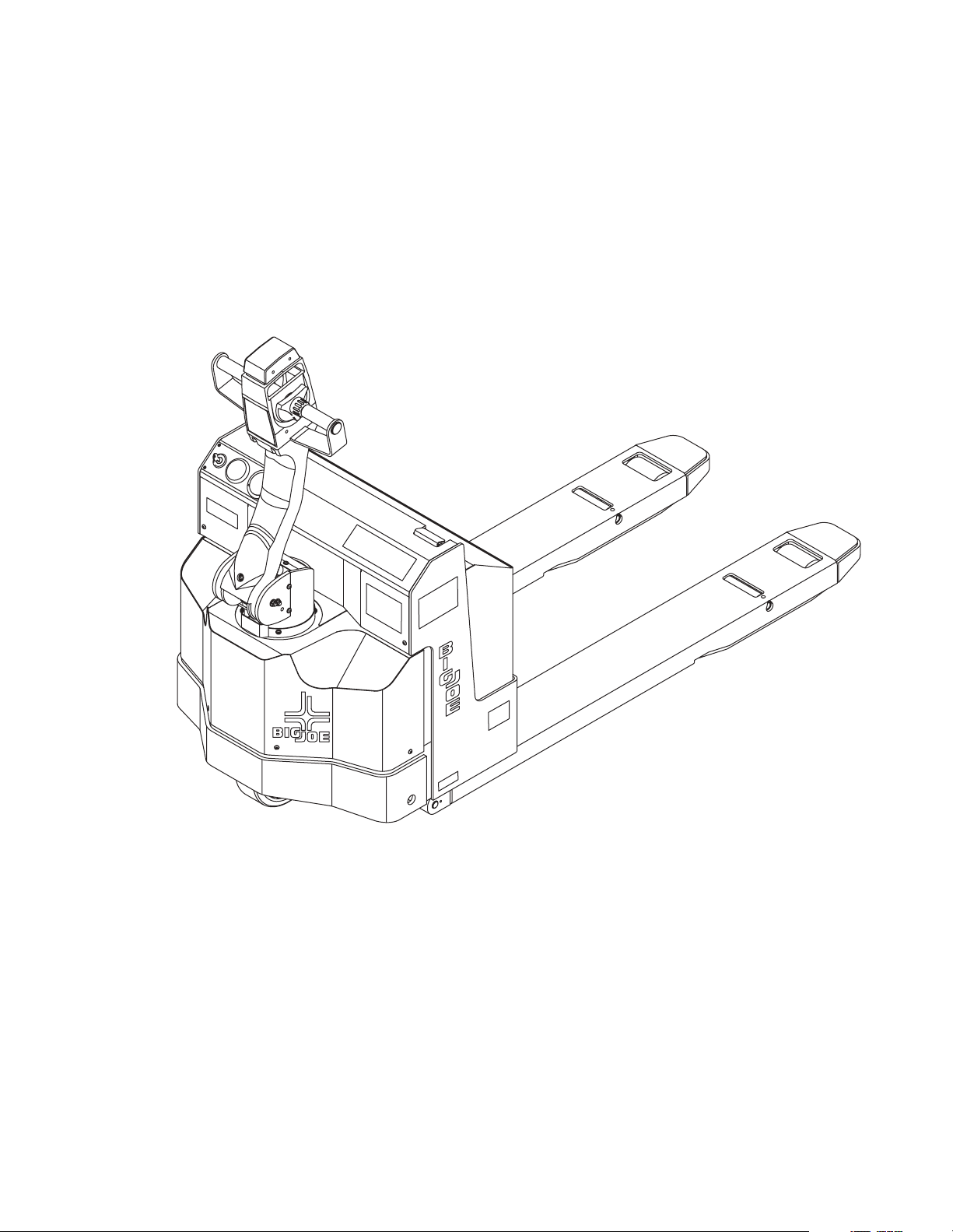
Section 7
PARTS LIST
PPT0104-901336 7-1
Page 68
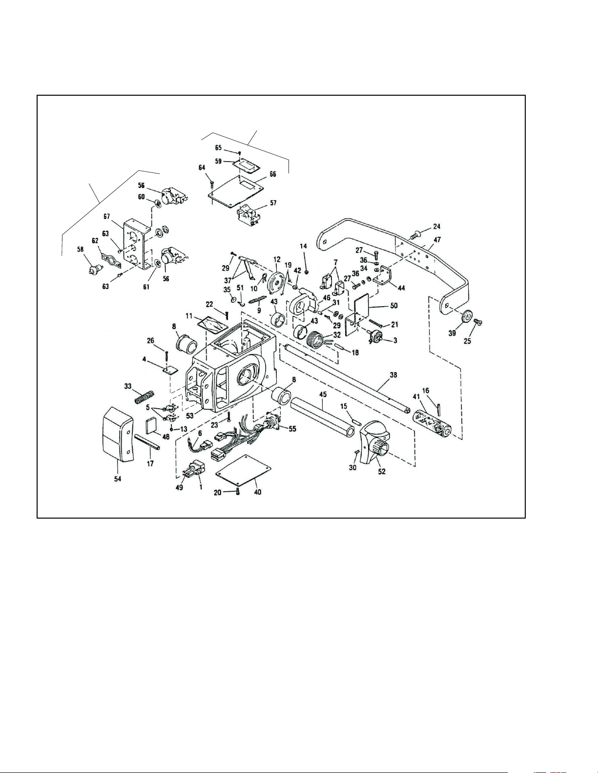
7-1. CONTROL HEAD ASSEMBLY
Push Button
Switch
Assembly
High Speed
Cutout Switch
Assembly
I-7007
Figure 7-1. Control Head Assembly
7-2 PPT0104-901336
Page 69

INDEX
NO.
- 505360-04 Control Head
1 005652 Pin Housing 1
2 - Not Used
3 017580 Potentiometer 1
4 018202 Switch Insulator 1
5 020669 Micro Switch 2
6 505323 Wire Harness Assembly 1
7 020775 Micro Switch 2
8 052956 Flanged Bearing 2
9 053366 Return Spring 1
10 056131 Hose Clamp 1
11 056617 Forward-Reverse Decal 1
12 057262 Potentiometer Disk 1
13 059633 Hex Lock Nut, 2-56 2
14 059634 Hex Lock Nut, 4-40 2
15 060579 Dowel Pin, 1/4X15/16 2
16 060942 Roll Pin, 1/8X1-1/4 2
17 061016 Roll Pin,1/4X3 2
18 061200-01 Spirol Pin, 3/16X1 1
19 061750 "E" Retainer Ring 2
20 067416 Pan HD. Screw, 6-32X1/2 4
21 068180 Round HD. Screw, 4-40X1-1/2 2
22 069462 Flat HD. Slotted Screw, 6-32X3/4 2
23 069463 Flat HD. Slotted Screw, 6-32X1 2
24 069478 Phillips Flat HD. Screw, 1/4-20X3/4 4
25 069715 Socket Flat HD. Hex Screw, 1/4-20X3/4 2
26 070486 Pan HD. Screw, Brass 2
27 072400-01 Slotted Hex Screw, 6-32X1/2 4
28 - Not Used
29 072415 Pan HD. Screw, Thread Cutting, 4-40X5/8 2
30 073461 Socket Set Screw 2
31 074711 Connection Rod Spacer 1
32 075088 Return Spring 1
33 075510 Compression Spring 2
34 077007 Washer 5
PART NO. PART NAME
NO.
REQD.
PPT0104-901336 7-3
Page 70
7-1. CONTROL HEAD ASSEMBLY
Push Button
Switch
Assembly
(CONTINUED)
High Speed
Cutout Switch
Assembly
I-7007
Figure 7-1. Control Head Assembly
7-4 PPT0104-901336
Page 71

INDEX
NO.
35 - Not Used
36 077204 Split Lock Washer #6 4
37 400546 Connector Rod Assembly 2
38 402827 Shaft 1
39 402828 Cap 2
40 402830 Bottom Cover 1
41 403358 Tube 2
42 074724 Spacer 1
43 402836 Spacer 2
44 402837 Bracket 1
45 402839 Tube 1
46 402840 Cam 1
47 402841 Handle Guard 1
48 402843 Pad 2
49 504538-01 Wire Assembly 5
50 505052 Switch Bracket Assembly 1
51 066052 Thumb Screw, 6-32 1
52 800272 Control Lever 2
53 800273 Control Handle 1
54 800274 Safety Cover 1
55 023201 Wire Harness Assembly 1
56 020697 Pushbutton Switch 2
57 020699 Cutout Switch, High Speed 1
58 020776 Horn Pushbutton Switch 1
59 056618 High Speed Decal 1
60 056641-03 Lift Decal 1
61 056641-04 Lower Decal 1
62 056624 Horn Decal 1
63 067415 Pan HD. Screw, 6-32X1/4 4
64 067416 Pan HD. Screw, 6-32X1/2 4
65 068190 Phillips Pan HD. Screw 2
66 402833 Top Cover 1
67 402842 Switch Plate 1
PART NO. PART NAME
NO.
REQD.
PPT0104-901336 7-5
Page 72
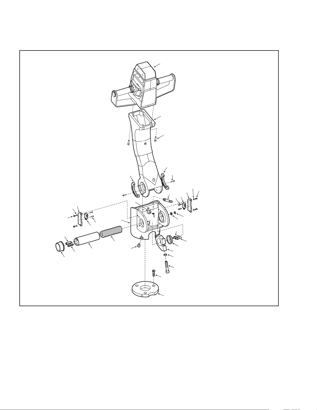
7-2. STEERING ARM
11
10
31
29
1
2
3
4
5
11
12
10
7
9
8
28
12
27
26
32
8
9
30
24
25
23
Figure 7-2. Steering Arm Assembly
21
22
13
14
15
16
17
18
19
20
I-7057
7-6 PPT0104-901336
Page 73

Item
No
1 1 506124-01 Control Head
2 1 800310 Steering Arm
3 4 065481 Screw, Cap, Socket Head
4 1 404196 Cam, Deadman Switch
5 - - Not used
6 4 065530 Screw, Cap, Button Head, Nylok
7 1 074451 Shock Absorber
8 4 065472 Screw, Cap, Socket Head
9 2 020775 Switch, Micro
10 2 404210 Plate, Mounting, Micro Switch
11 4 077209 Washer, Lock
12 4 065525 Screw, Cap, Button Head, Nylok
13 2 059426 Nut, Plain Hex
14 2 077210 Washer, Lock
15 1 285302 Pin, Spring
16 1 285303 Pin, Spring
17 1 052922 Bushing, Flange, Bronze
18 1 800204 Clamp, Tube
19 1 401127 Spacer
20 1 065569 Screw, Cap, Socket Head
21 3 067435-01 Screw, Hex Head, Countersunk, Metric
22 1 404189 Mounting Plate, Motor
23 4 069717 Screw, Hex Head, Countersunk
24 1 075060 Spring, Return
25 1 501371 Tube, Spring
26 1 061006 Pin, Roll, ¼ x 1 ¼
27 1 052925 Bushing, Flange, Bronze
28 1 061050 Pin, Roll, 3/8 x 1 ¼
29 2 053042 Bumper, Round
30 2 071377 Screw, Truss Head
31 1 404197 Cam, Creep Speed
32 1 506139 Adapter
Qty. Part No. Description
PPT0104-901336 7-7
Page 74
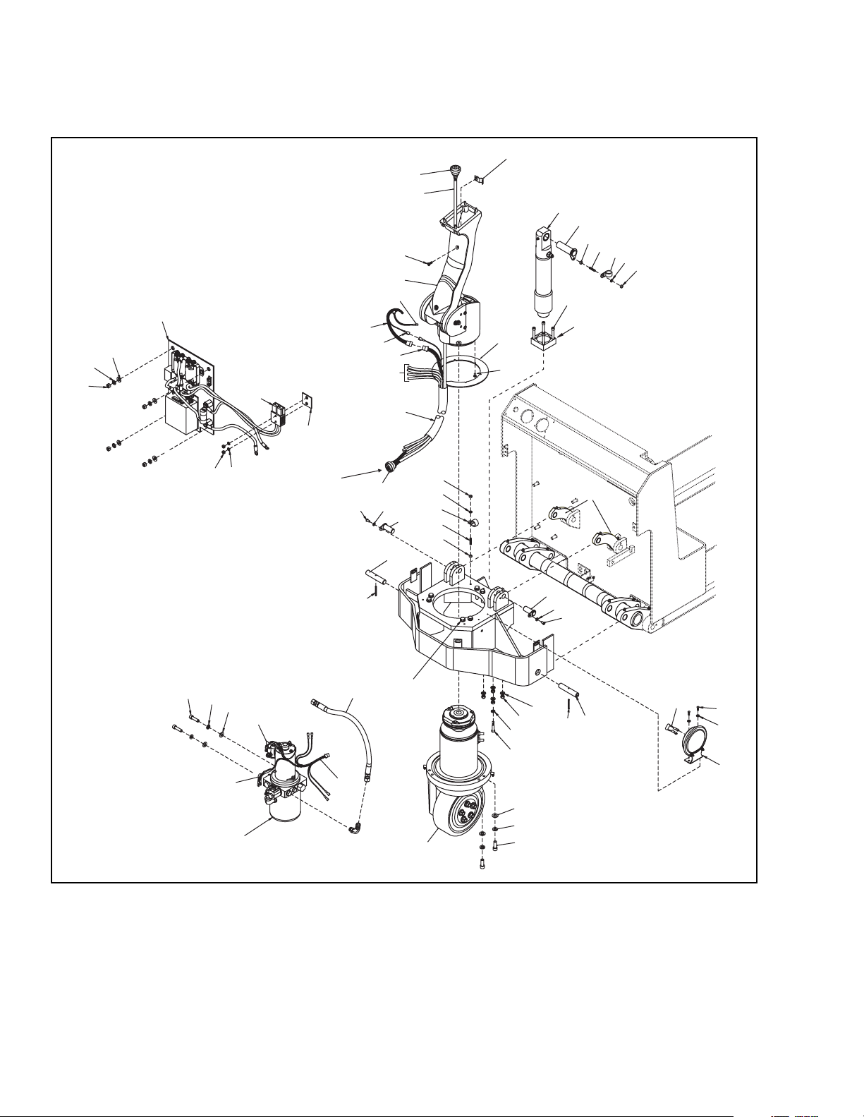
7-3. POWER SECTION PARTS
51
36
37
50
48
8
5
TO DRIVE MOTOR
49
TO CONTACTOR
PANEL
15
43
42
39
44
41
8
20
46
45
40
47
13
39
1
3
4
5
6
7
8
5
10
11
2
17
5
8
12
7
6
5
38
37
34
36
33
35
21
31
30, 26
32
29
Figure 7-3. Power Section Parts
24
25
23
26
27
28
22
13
8
21
15
20
16
17
18
19
I-7057
7-8 PPT0104-901336
Page 75

Item
No
1 1 504364 Clamp Assembly, Clinch Nut
2 1 404220 Ring Guard
3 1 506146 Hydraulic Cylinder
4 1 506142 Pin - Keeper
5 8 059421 Nut - Hex, ¼-20 UNC
6 2 075620 Stud, Threaded ¼-20 x 1¼ Lg
7 2 056135 Clamp - Cable, Cushioned
8 7 077209 Washer - Lock, ¼
9 -- Not Used
10 4 065557 Screw-SHCS, 5/16-24 UNF x 1¾ Long
11 1 404178 Bar - Cylinder, Mount
12 2 506141 Link Assembly
13 4 506137 Pin - Keeper
14 -- Not Used
15 4 065476 Screw-HHCS, ¼-20 UNC x 1/2 Long
16 1 504096 Suppressor Assembly - Spike, Horn
17 8 065531 Screw-BHCS, #10-32 UNC x ½ Long
18 2 077207 Washer - Lock, #10
19 1 009602 Horn
20 2 403977 Shaft, Pivot
21 2 061200-04 Spring, Pin - Slotted, .19 x 1 ¾ Long
22 4 077210 Washer - Lock, 5/16"
23 4 059427 Nut - Hex, 5/16-24 UNC
24 1 077031 Washer - Flat, ¼
25 1 063483 Screw - HHCS, ¼-20 x 1 ¾ Lg
26 8 077212 Washer - Lock, 7/16
27 2 077087 Washer, Flat, 13/32 I.D.
28 2 067445-01 Screw, SHCS, M 10 x 20 mm Lg
29 1 506150 Power Drive Wheel, Transmission & Motor
30 6 067443-01 Bolt - HHCS, M10 x 50 mm Long
Qty. Part No. Description
PPT0104-901336 7-9
Page 76
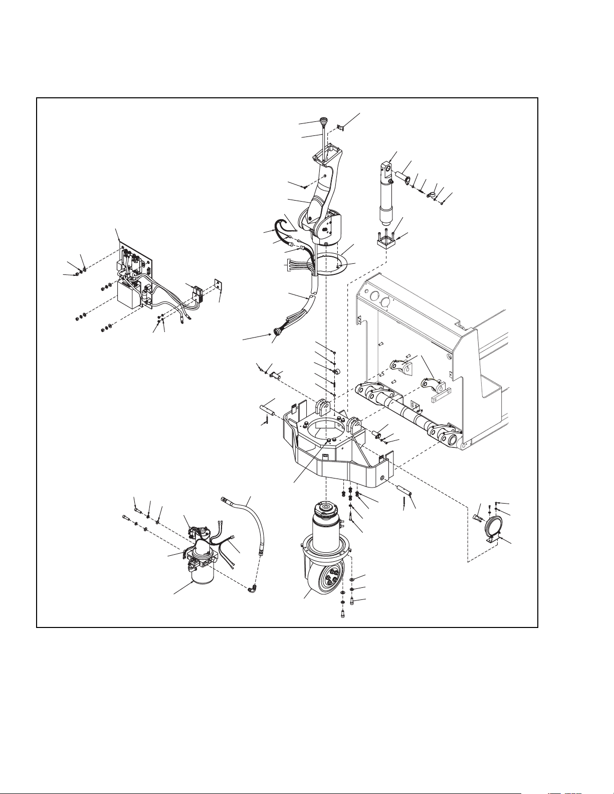
7-3. POWER SECTION PARTS
51
36
37
50
48
8
5
TO CONTACTOR
PANEL
(CONTINUED)
43
42
TO DRIVE MOTOR
49
39
15
45
44
41
8
20
46
40
47
13
39
1
3
4
5
6
7
8
5
10
11
2
17
5
8
12
7
6
5
38
37
34
36
33
35
21
31
30, 26
32
29
Figure 7-3. Power Section Parts
24
25
23
26
27
28
22
13
8
21
15
20
16
17
18
19
I-7057
7-10 PPT0104-901336
Page 77

Item
No
31 1 504312-15 Hose Assembly - 3/8
32 1 023270 Wire Harness Assembly, Hydraulic
33 1 016594 Pump, Motor & Reservoir Assembly - 24 V
34 1 504116 Suppressor Assembly - Spike, Lower Solenoid
35 1 504097 Suppressor Assembly - Spike, Motor Solenoid
36 6 077056 Washer - Flat, 3/8
37 6 077211 Washer - Lock, 3/8"
38 2 064605 Screw-HHCS, 3/8-16 UNC, 1" Long
39 1 023266 Cable Assembly, Control
40 1 901451 Oversleeve - Cable, Braided
41 1 023272 Wire Harness Assembly - Brake, Switches
42 1 021257 Terminal, Tab, Male, ¼, Insulated
43 1 023273 Wire Harness Assembly - Switches
44 1 021249 Terminal, Tab, Female, 3/16
45 1 506138 Arm Assembly
46 1 069478 Screw - PFH, ¼-20 x ¾ Long
47 1 005640 Connector, Circular
48 1 005401 Connector, Battery
49 1 404225 Spacer - Connector
50 4 059429 Nut - Hex, 3/8-16 UNC
51 1 506143 Panel Assembly - Elec, PPT
Qty. Part No. Description
PPT0104-901336 7-11
Page 78
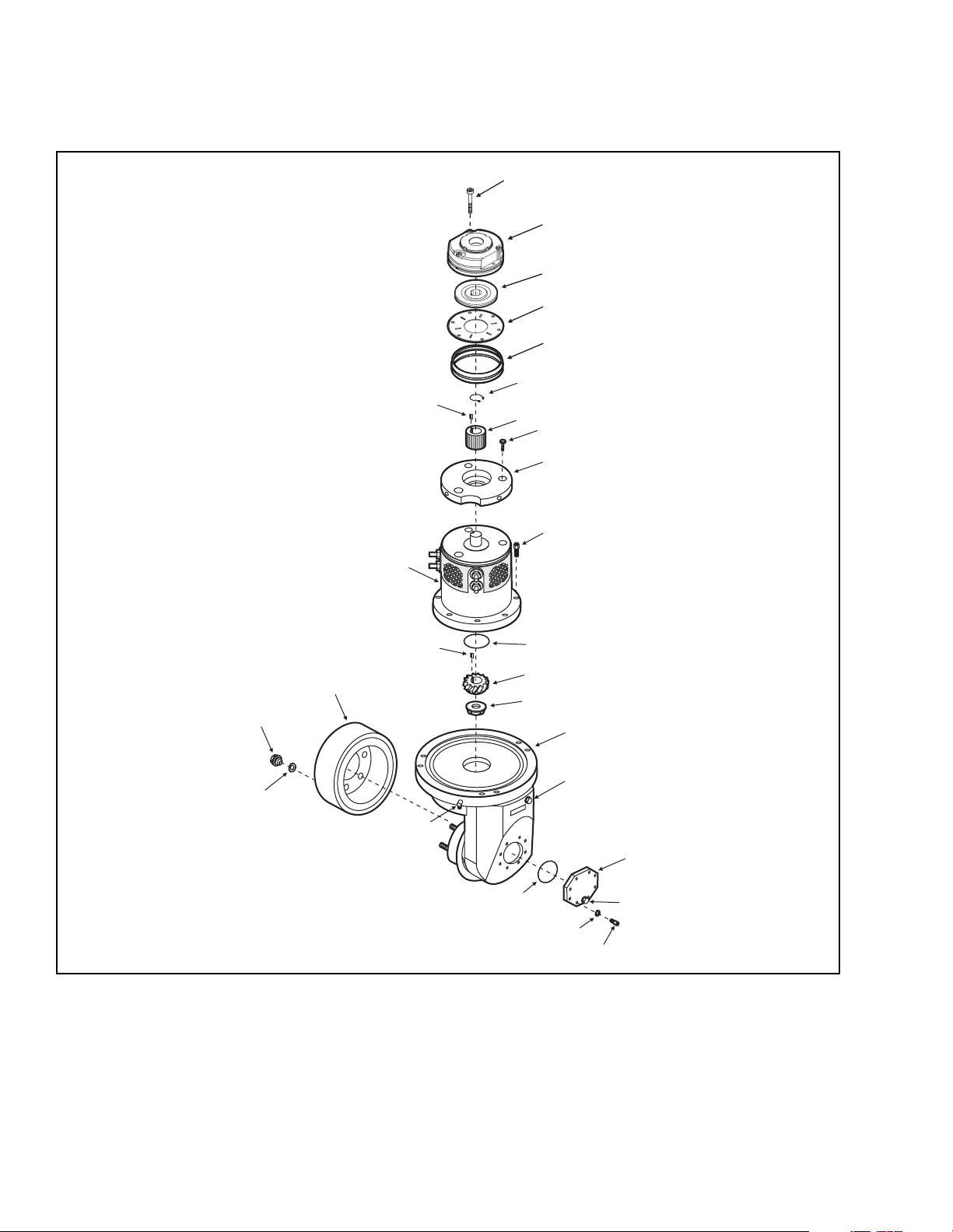
7-4. TRANSMISSION, MOTOR AND BRAKE ASSEMBLY
7
12
1
1
2
2
3
3
4
4
5
5
6
8
9
10
11
14
13
15
27
16
26
17
18
25
24
23
22
21
Figure 7-4. Transmission, Motor and Brake Assembly
19
20
I-7051
7-12 PPT0104-901336
Page 79

Item
No
1 1 901700 Screws (Set of 3), Brake Assembly Mounting
2 1 901701 Stator, Brake
3 1 901702 Rotor, Aluminum
4 1 901703 Plate, Friction
5 1 901704 Cover, Brake
6 1 901705 Clip, Spring
7 1 901706 Woodruff Key
8 1 901707 Gear, Splined
9 3 067435-01 Screw, Allen Head, Countersunk, Metric, M8 x 1.25 x 35 Lg
10 1 404189 Motor End Plate
11 8 901708 Screw-Hex Socket, FL HD, M8 x 35 mm Long
12 1 016051 Motor
13 1 901709 O-ring
14 1 901710 Woodruff Key
15 1 901711 Gear, Spiral
16 1 901712 Nut,
17 1 506151 Transmission Assembly
18 1 901713 Oil Filler Plug
19 1 901714 Plate, Transmission Service Cover
20 1 901715 Oil Drain Plug
21 8 901716 Screw, Hex Head
22 8 901717 Washer,
23 1 901718 O-ring
24 1 901719 Grease Fitting
25 5 901720 Washer,
26 5 901721 Lug Nut
27 1 506161-01 Wheel Assembly
Qty. Part No. Description
PPT0104-901336 7-13
Page 80
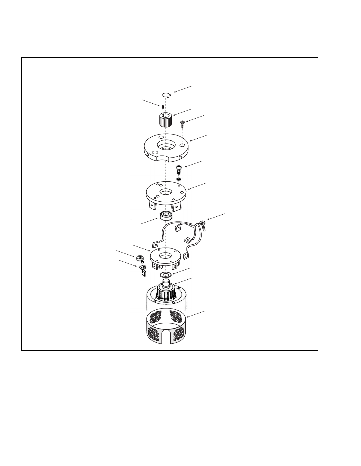
7-5. DRIVE MOTOR REPAIR PARTS
1
2
3
4
5
6
7
8
9
10
11
12
13
14
Figure 7-5. Drive Motor Repair Parts
15
I-7022
7-14 PPT0104-901336
Page 81

Item
No
- 1 016051 Motor, Drive
1 1 901722 Clip, Spring
2 1 901723 Woodruff Key
3 1 901724 Gear, Splined
4 3 067435-01 Allen Head Countersunk Screw, Metric
5 1 404189 Motor, End Plate
6 4 901725 Bolt, Hex Head,
7 1 901726 Head, Commutator End
8 1 901727 Brush Lead and Terminal Connector
9 1 901728 Bearing, Commutator End
10 1 901729 Brush Box Assembly
11 1 901730 Spring, Brush (Set of four)
12 1 901731 Brush (Set of four)
13 1 901732 Washer, Spring
14 1 901733 Armature Assembly
15 1 901734 Headband Assembly
Qty. Part No. Description
PPT0104-901336 7-15
Page 82

THIS PAGE INTENTIONALLY LEFT BLANK
7-16 PPT0104-901336
Page 83
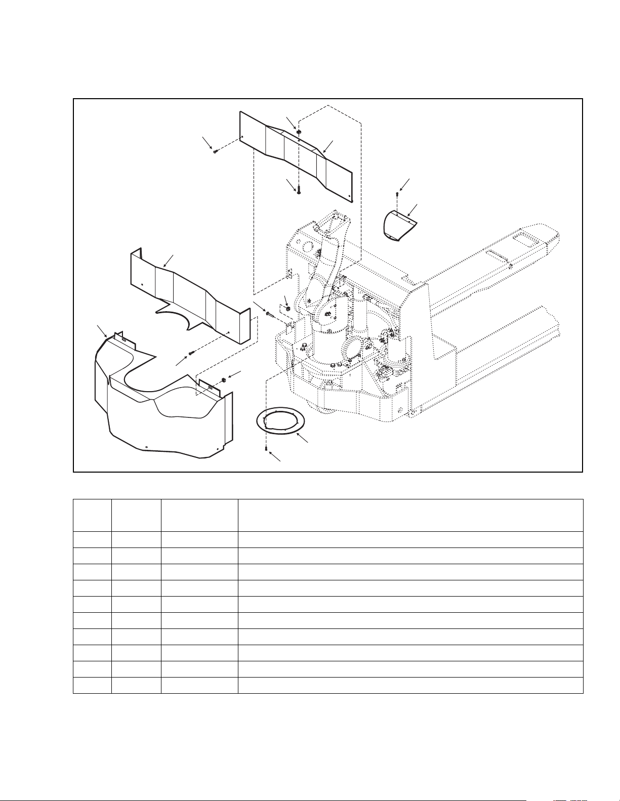
7-6. BASE AND FRAME PARTS
4
9
68
7
66
10
1
46
2
64
8
62
65
7
4
66
6
69
67
5
65
4
63
46
3
1
Figure 7-6. Base Frame and Parts
Item
No
1 9 065531 Screw-BHCS, #10-32 UNC x ½ Long
2 1 404221 Cover, Brake
3 1 404220 Ring, Guard
4 7 059940-01 Nut, Retainer, ¼-20
5 2 065525 Screw-BHCS, ¼-20 UNC x 5/8 Long
6 1 506144 Cover, Main
7 5 065527 Screw-BHCS, ¼-20 UNC x 1.0 Long
8 1 404217 Cover, Middle
9 2 065532 Screw-BHCS, ¼-20 UNC x 3/8 Long
10 1 404216 Cover, Upper
Qty. Part No. Description
PPT0104-901336 7-17
Page 84
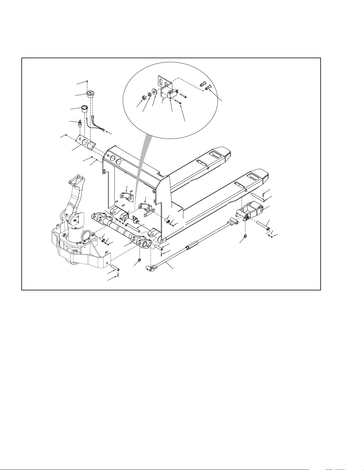
7-7. FORK SECTION PARTS
24
27
26
25
21
10
19
18
17
THREADED STUDS WELDED
TO MOTOR COMPARTMENT
WALL.
16
24
23
22
14
TO
CONTROLLER
11
13
10
11
8
7
2
12
12
10
9
13
10
11
7
2
3
Figure 7-7. Fork Section Parts
6
2
1
4
5
10
11
3
I-7049
7-18 PPT0104-901336
Page 85

Item
No
1 2 403980 Shaft - Pivot
2 4 061200-03 Spring, Pin - Slotted, .19 x 1¼ Long
3 A/R 077036 Washer - shim, 1.25 OD x .766 ID
4 2 506129 Load Wheel and Housing Assembly
5 2 506147 Pin, Keeper
6 2 506135-
7 2 404183 Shaft - Pivot
8 1 506125 Torsion Tube
9 2 506126 Pin - Keeper
10 8 077209 Washer, Lock, ¼"
11 6 065476 Screw-HHCS, ¼-20 UNC x 1/2 Long
12 2 506141 Assembly - Link
13 4 506137 Pin - Keeper
14 4 077204 Washer - Lock, #6
15 -- -- Not Used
16 2 065472 Screw-SHCS, #4-40 UNC x ¾ Long
17 1 020775 Switch - Miniature, Snap Action
18 1 404239 Bracket - Switch
19 2 077031 Washer - Flat, ¼
20 -- -- Not Used
21 2 059421 Nut - Hex, ¼-20 UNC
22 4 059412 Nut - Hex, #6-32 UNC
23 1 404198-01 Plate - Cover, Gage
24 7 068233 Screw - SRH, #6-32 x ¾ Long
25 1 020725 Key switch
26 1 010617-02 Battery Capacity Indicator - 24V
27 1 015604 Hour Meter - 24V
Qty. Part No. Description
Tie Rod Assembly - 48" ForkTie Rod Assembly - 42" ForkTie Rod
0150613502506135-03
Assembly - 36" Fork
PPT0104-901336 7-19
Page 86

THIS PAGE INTENTIONALLY LEFT BLANK
7-20 PPT0104-901336
Page 87
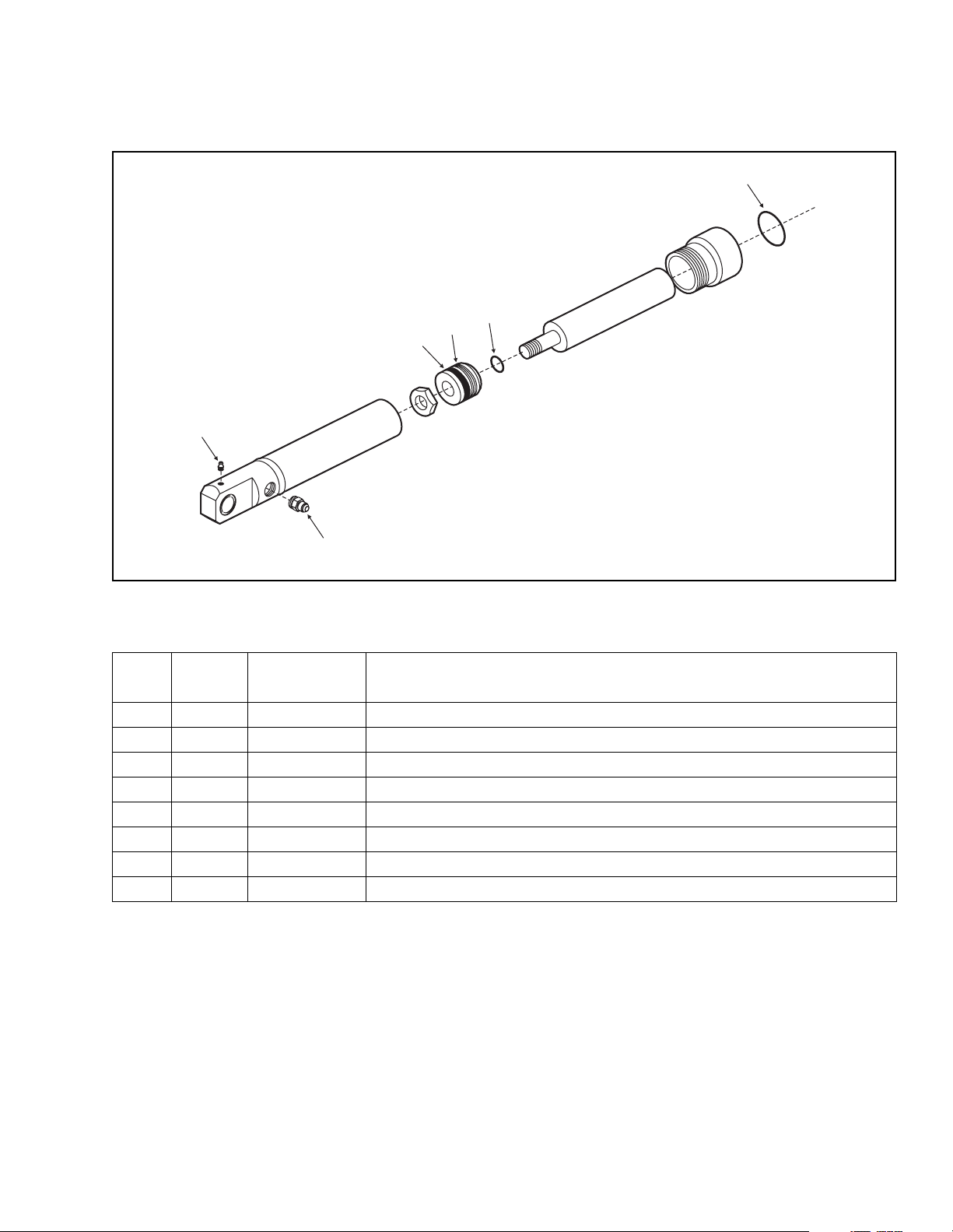
7-8. HYDRAULIC CYLINDER PARTS
5
1
2
3
4
6
Figure 7-8. Hydraulic Cylinder Parts
Item
No
-- 1 506154 Hydraulic Cylinder Assembly
1* 1 901735 O-ring
2* 1 901736 O-ring
3* 1 901737 Seal,
4* 1 901738 Seal,
5 1 025716 Grease Fitting, Straight, ¼-28 NPT
6 1 026922 Fitting, Hydraulic, 9/16-18 SAE, 9/16-18 JIC
Qty. Part No. Description
1 901739 Packing Kit
I-7052
PPT0104-901336 7-21
Page 88
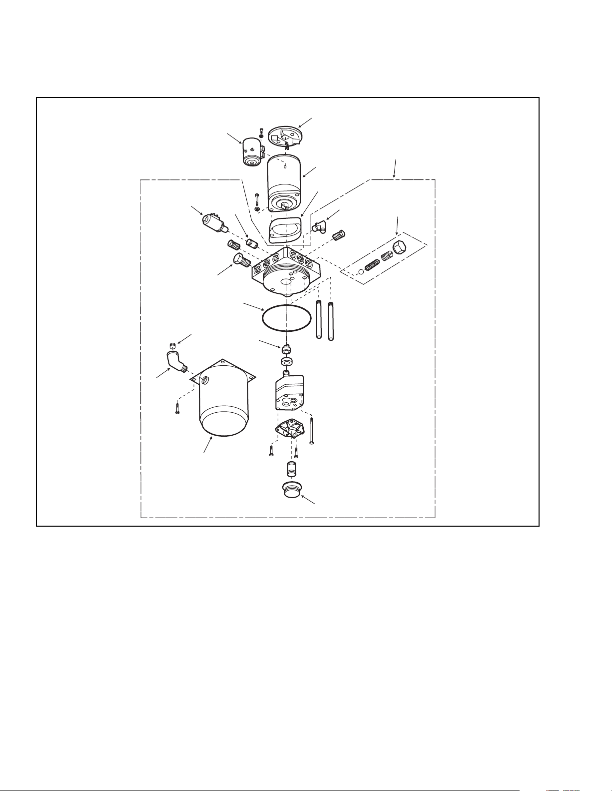
7-9. HYDRAULIC CYLINDER PARTS
16
14
13
15
12
1
4
2
3
5
6
10
11
9
8
7
Figure 7-9. Hydraulic Pump, Motor and Reservoir Assembly Parts
I-7058
7-22 PPT0104-901336
Page 89

Index
No.
1 1 901432 Cap/Brush Kit
2 1 901433 24V Motor
3 1 901434 Motor Adapter
4 1 901437 Adapter-Pump-Res Kit
5 1 025535 9/16 Elbow
6 1 901442 Relief Valve Assy
7 1 901440 Filter
8 1 901441 Reservoir
9 1 026703 Elbow
10 1 076701 Breather Plug
11 1 901439 Coupling
12 1 901438 O-Ring
13 1 901436 Check Valve
14 1 048133 Solenoid Release Valve
15 1 901435 Flow Regulator
16 1 020715 24V Solenoid
Qty PartNo. Part Name
PPT0104-901336 7-23
Page 90
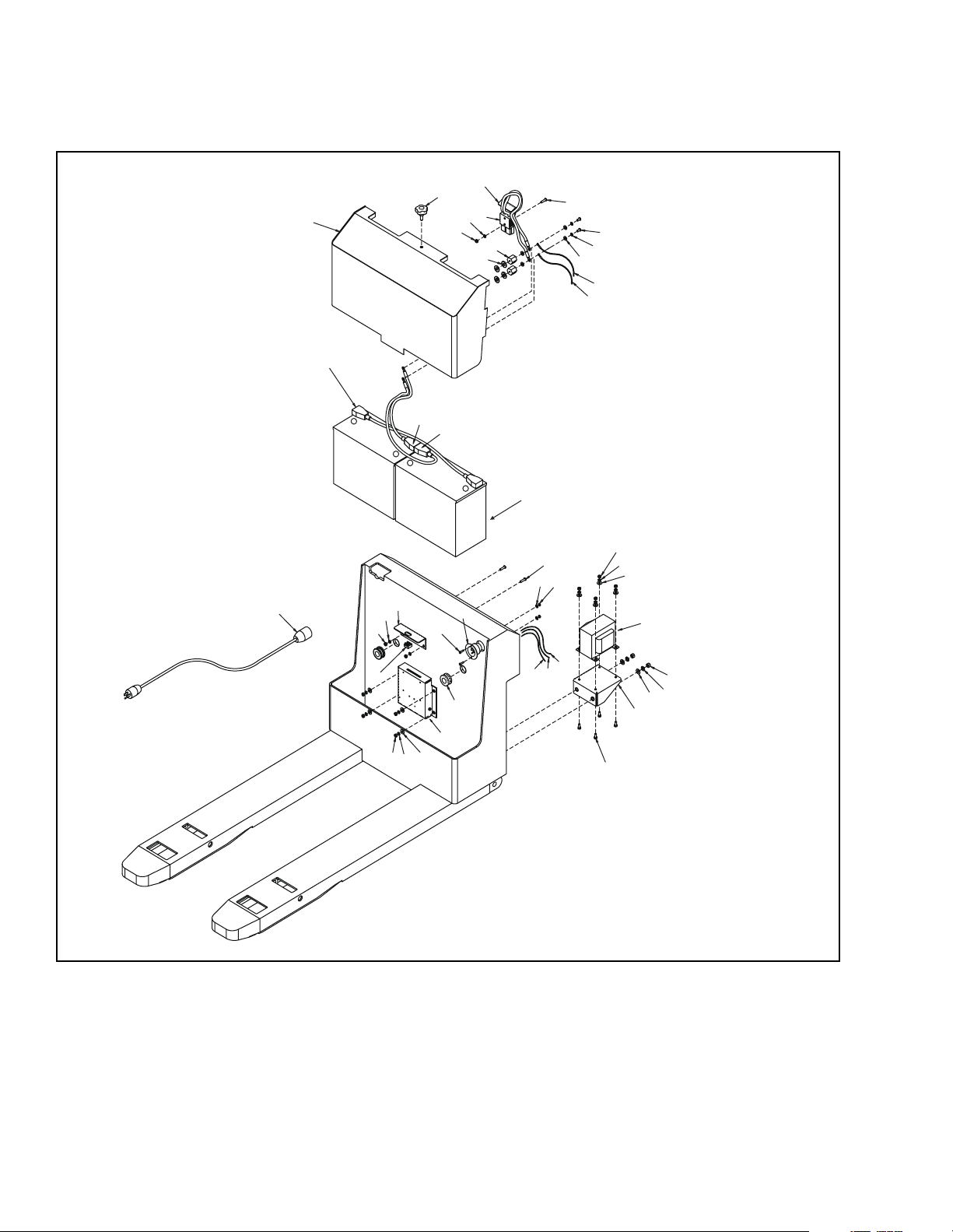
7-10. BATTERY INSTALLATION PARTS
2
4
17
29
20
23
14
7
12
26
9
20
11
35
TO BATTERY CHARGER
}
TRANSFORMER
34
19
20
+
13
6
5
-
+
8
25
10
37
31
16
24
32
28
33
29
20
22
15
36, 38
21
23
30
-
29
18
36, 39
22
29
20
27
I-7054
Figure 7-10. Battery Installation Parts
7-24 PPT0104-901336
Page 91

Item
No
1
2 1 506152 Cover, Battery
3 -- -- Not Used
4 1 506123-01 Cable Assembly - Battery, 4 AWG
5 1 505469-05 Cable Assembly - Battery
6 1 505469-06 Cable Assembly - Battery
7 1 505627-03 Connector Assembly, Battery
8 1 005454 Connector, Inlet, Flanged
9 2 010614 Standoff, Insulator
10 2 057519 Grommet
11 4 077105 Washer, Flat, ¼, Brass
12 2 068478 Screw, RHCS, ¼-20 UNC x 1.25 Long
13 1 404206 Bracket, Battery Cover
14 1 404211 Handle, Connector, Red Metal
15 1 404229 Shelf, Transformer
16 2 077204 Washer, Lock, #6
17 1 057964 Plastic Knob
18 1 059940-02 Nut, Retainer, 3/8-16 UNC
19 1 005810 Cord, AC, Input, Charger
20 14 077209 Washer, Lock, ¼
21 2 077211 Washer, Lock, 3/8
22 8 077031 Washer, Flat, ¼
23 6 077056 Washer, Flat, 3/8
24 2 063480 Screw, HHCS, ¼-20 UNC x 1" Long
25 2 068233 Screw, RHCS, #6-32 UNC x ¾" Long
26 2 070489 Screw, HHCS, ¼-20 UNC x 5/8" Long, Brass
27 4 063477 Screw, HHCS, ¼-20 UNC x 5/8" Long
28 2 059412 Nut, Hex, #6-32 UNC
29 12 059421 Nut, Hex, ¼-20 UNC
30 2 059429 Nut, Hex, 3/8-16 UNC
31 1 023269 Harness Assembly, AC Receptacle, #20
32 1 023267-01 Wire Assembly, Black, #19
33 1 023267-02 Wire Assembly, Green
34 1 505675-07 Wire Assembly, #10 AWG, Black
35 1 505675-08 Wire Assembly, #10 AWG, Red
36 1 004988 Charger Assembly, 24V, 25A
37 033150 150AH Industrial Battery
38 1 901740 Transformer
39 1 901741 Circuit Board Assembly
Qty. Part No. Description
003151 170AH Industrial Battery
003209 200 AH Industrial Battery
003152 220 AH Industrial Battery
003219 195 AH Maintenance Free Battery with charger
506193 155 AH Maintenance Free Battery with charger
PPT0104-901336 7-25
Page 92
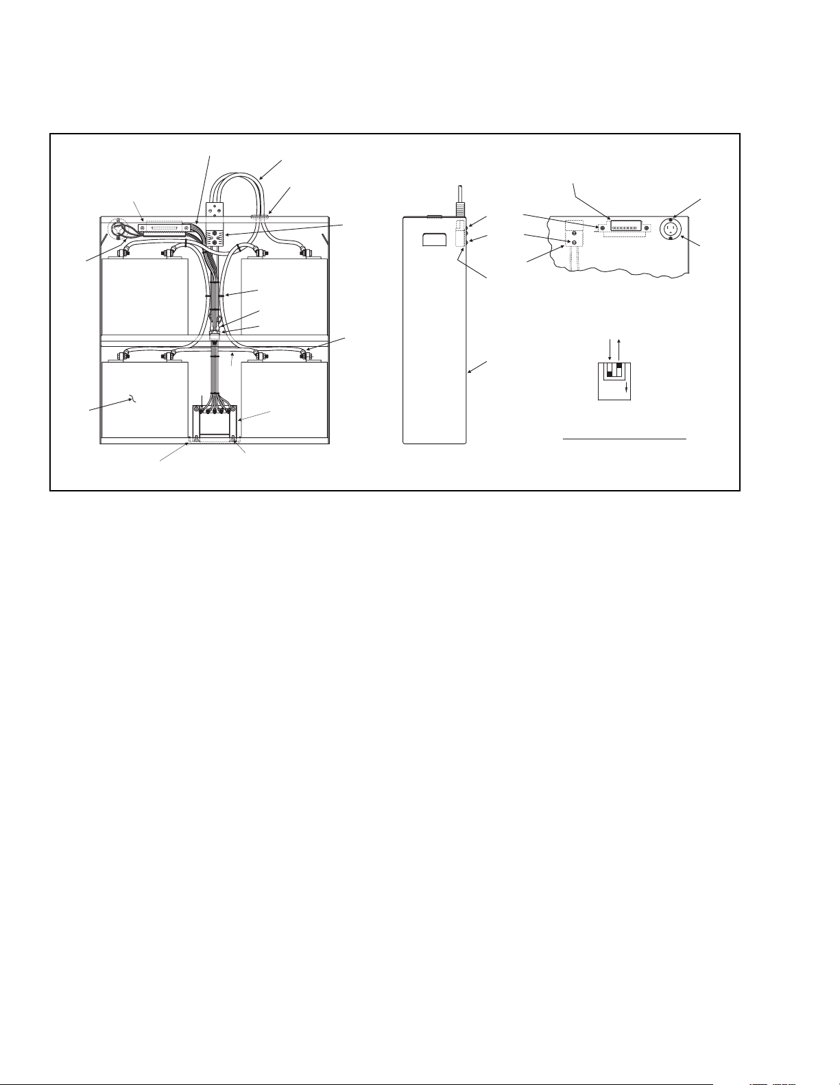
7-11. BATTERY CHARGER ASSEMBLY
26, 27,
28
30
21
31
22, 23, 24
2
1
29
20
14
15
9
16
17
18
19
21
5
4,
Figure 7-11. Battery Charger Assembly
6, 7, 8
3, 4, 5
2
1
10 - POSITION WINDOWS IN
DECAL OVER LED's
11, 12
13
9
2
1
ON
BATTERY TYPE DIP
SWITCH SETTING DETAIL
(GELL CELL MODE)
I-7063
7-26 PPT0104-901336
Page 93

Item
No
1 1 404305 Housing, Battery
2 1 403688 Spacer, Connector
3 2 068478 Screw, SLRH, ¼-20 x 1 ¼" Lg
4 6 077209 Washer, Lock, Split, ¼"
5 6 059421 Nut, Hex, ¼-20
6 2 071376 Screw, PHTH, 10-32 x ½" Lg
7 2 077208 Washer, Lock, Split, #10
8 2 059416 Nut, Hex, #10-32
9 1 506122 Connector Assembly, Charger
10 1 056680 Decal, Charger
11 2 077204 Washer, Lock, Split, #6
12 2 059412 Nut, Hex, #6-32
13 1 005454 Connector, Inlet, Flanged, AC
14 1 505466-02 Connector Assembly, Battery
15 1 057511 Grommet
16 8 056113 Tie, Harness
17 4 021718 Terminal, ¼ Spade, 16 AWG
18 1 003403 Circuit Breaker
19 2 504150-31 Cable Assembly - 4 AWG
20 1 504150-32 Cable Assembly - 4 AWG
21 1 004987 Charger Kit, 24V, 25A
22 A/R 023010 Wire, Stranded, 10 AWG, Red
23 A/R 023011 Wire, Stranded, 10 AWG, Black
24 A/R 023036 Wire, Stranded, 10 AWG, White
25 5 005471 Connector, Splice, Crimp, 10 AWG
26 A/R 023000 Wire, Stranded, 16 AWG, White
27 A/R 023004 Wire, Stranded, 16 AWG, Green
28 A/R 023018 Wire, Stranded, 16 AWG, Black
29 7 021262 Terminal, Ring, 10 AWG
30 4 003221 Battery, 6V, GMF
31 1 404306 Retainer, Battery
32 1 021206 Terminal, Ring, ¼" Dia
Qty. Part No. Description
PPT0104-901336 7-27
Page 94
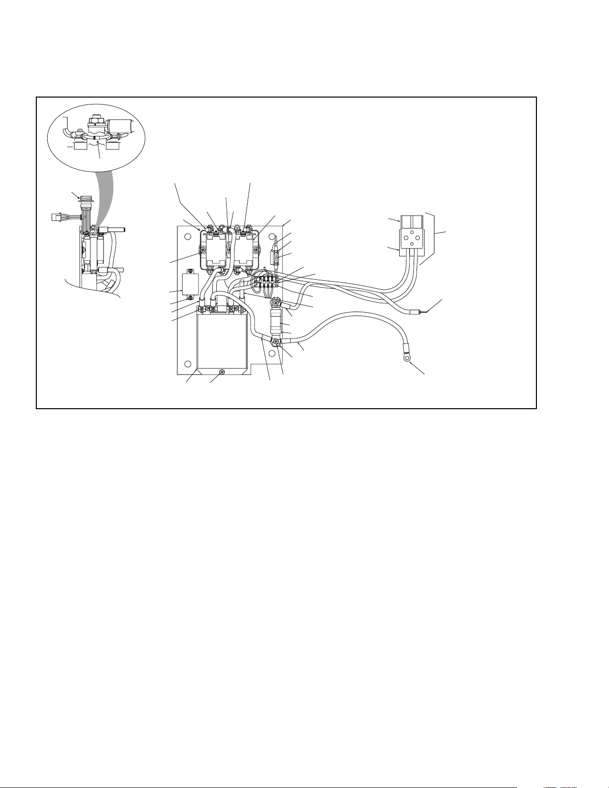
7-12. CONTACTOR PANEL ASSEMBLY PARTS
34
33
6 - CABLE F2 TO DRIVE MOTOR
6 - CABLE F1 TO DRIVE MOTOR
24, 22, 20
POS
A2
24, 22
2
POS
13
14
FWDREV
9
17
29
3
10, 11
MAX15 AMP
23, 37
41
40
-
+
7
23, 37
30
12
13
35, 36
39
38
NEG
5 - CABLE TO HYD
PUMP/MOTOR
7
4
CABLE TO HYD
PUMP/MOTOR
I-7053
NEG
EG
N
POS
3
120AMP
MAXIMUM
31, 22, 26
3
16
15
5
5
3
1
32, 22,
20
14
25, 23, 21
1
27, 19, 18
8
Figure 7-12. Contactor Panel Assembly Parts
7-28 PPT0104-901336
Page 95

Item
No
1 1 504150-17 Cable Assembly - #4 AWG
2 1 504150-25 Cable Assembly - #4 AWG
3 1 504150-26 Cable Assembly - #4 AWG
4 1 504150-27 Cable Assembly - #4 AWG
5 1 505181-07 Cable Assembly - #4 AWG
6 2 504150-28 Cable Assembly - #4 AWG
7 1 505466-01 Battery Connector Assembly
8 1 005468 Controller - XSTR, 250A, 24V
9 2 005667 Solenoid, Contactor, 24V
10 1 008904 Fuse Holder
11 1 008910 Fuse, AGX Type, 15 Amp
12 1 008918 Fuse, 120 Amp
13 2 010614 Standoff, Insulator
14 1 018411 Relay, Mount, Flange, AC
15 2 403548 Buss bar
16 2 403549 Buss bar
17 1 404207 Plate, Sub-panel
18 4 077210 Washer, Lock, 5/16
19 4 059526 Nut, Hex, Jam, 5/16-18 UNC
20 3 077031 Washer, Flat, ¼
21 4 077007 Washer, Flat, #6
22 8 077209 Washer, Lock, ¼
23 5 077204 Washer, Lock, #6
24 4 070481 Screw, PH, RD, HD, ¼-20 UNC x 7/16" Long
25 2 068235 Screw, PH, RD, HD, #6-32 UNC x ¼" Long
26 2 070489 Screw, PH, RD, HD, ¼-20 UNC x 5/8" Long, Brass
27 4 063552 Screw, HHCS, 5/16-18 UNC x 5/8" Long
28 2 075623-01 Stud-Weld, ¼-20 UNC x ½" Long
29 1 056504 Decal, Fuse, 15 Amp
30 1 056562 Decal, Fuse, 120 Amp
31 4 077105 Washer, Flat, ¼, Brass
32 2 070475 Screw, PH, RD, HD, ¼-20 UNC x 3/8" Long
33 2 005996 Diode Assembly, Contactor
34 1 023265 Harness Assembly, Panel, Contactor
35 1 505931 Diode Block Assembly, Hour Meter
36 1 010625 Pad, Insulating
37 3 068230 Screw - PH RD HD, #6-32 UNC x 3/8" Long
38 1 504150-29 Cable Assembly - #4 AWG
39 1 504150-30 Cable Assembly - #4 AWG
40 1 404211 Handle, Connector, Red Metal
41 1 005401 Connector, Battery
Qty. Part No. Description
PPT0104-901336 7-29
Page 96
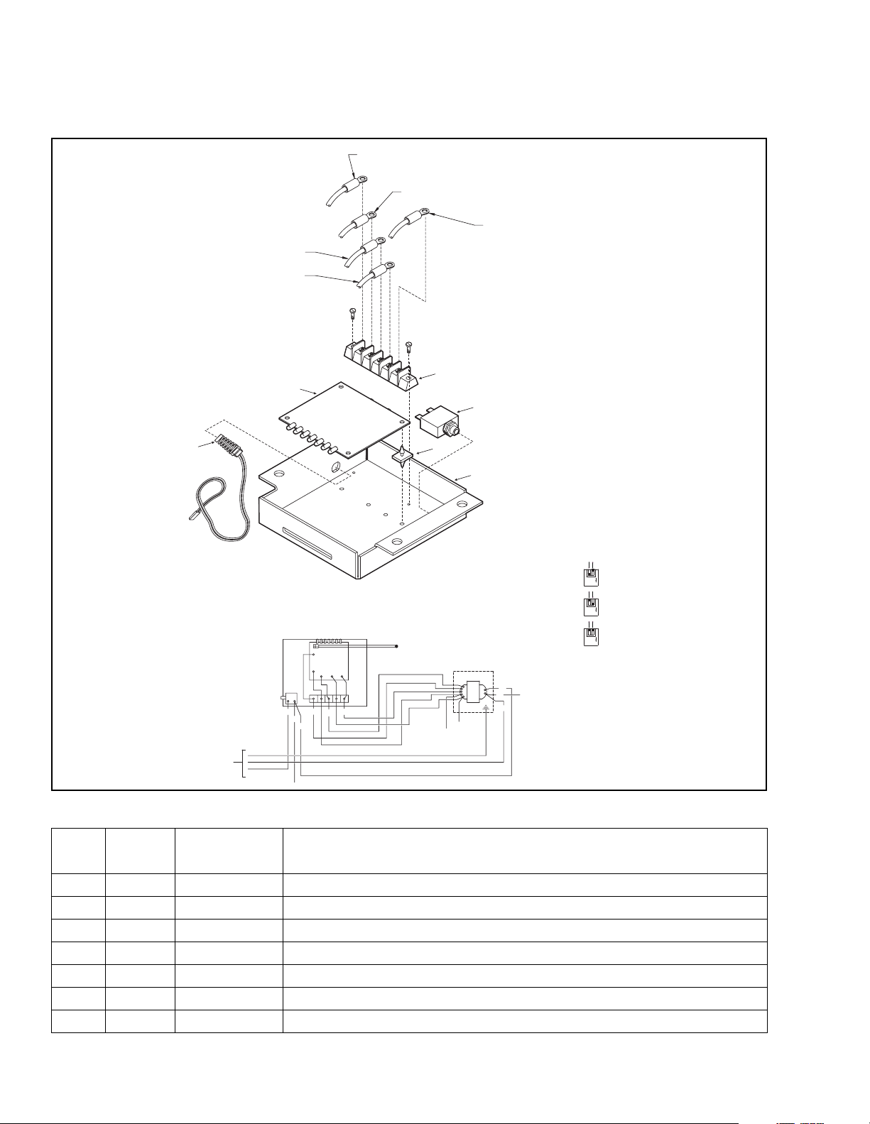
7-13. CHARGER CIRCUIT BOARD
WIRE #18 (WHITE) TO
TRANSFORMER-SEE DIA
WIRE #17 (WHITE) TO
TRANSFORMER-SEE DIA
BLACK WIRE (NO NUMBER) TO
TRANSFORMER-SEE DIA
5
GREEN
WHITE
TO AC
RECEPTACLE
BLACK
WHITE
18
RED
E
IT
H
W
17
A
L
B
6
LOGIC BOARD HEAT SINK/ENCLOSURE
LOGIC
BOARD
BLUE
CIRCUIT
BREAKER
BLACK
RED
WHITE
WHITE
TERMINAL
STRIP
16
19
19
19
18
17
RED WIRE (NO NUMBER) TO
TRANSFORMER-SEE DIA
HITE
W
16
K
C
THERMISTER
WHITE 17
WHITE 16 (BLUE)
WHITE 18
BLACK
WIRE #16 (WHITE) TO
TRANSFORMER-SEE DIA
1
2
3
4
BATTERY CHARGER (REF) SEE ORDER ENTRY FORM
SET DIP SWITCHES ON CHARGER LOGIC BOARD AS REQUIRED:
506149-01 DEFAULT SETTING-GEL (GMF)
506149-02 ABSORBED GLASS MAT (AMF)
506149-03, -04 & -05 FLODDED CELL
RED
TRANSFORMER
RED
BLACK
GREEN
20
WHITE
19
20
BLACK
WHITE
2
1
ON
2
1
ON
2
1
ON
I-7055
Figure 7-13. Charger Circuit Board
Item
No
Qty. Part No. Description
1 901741 Circuit Board Assembly
1 1 021261 Terminal Strip, 5 Pole
2 1 003403 Circuit Breaker, Thermal
3 4 010627 Support, Mounting, Circuit Board
4 1 404235 Cover, Circuit Board
5 1 901742 Thermister
6 1 901743 Circuit Board, Charger
7-30 PPT0104-901336
Page 97
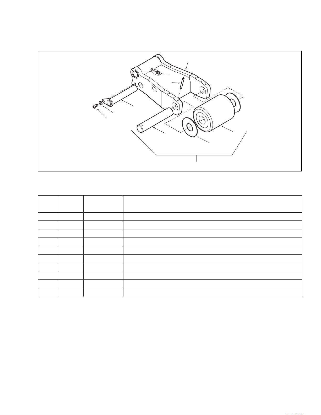
7-14. LOAD WHEELS
1
8
9
5
6
7
4
10
Figure 7-14. Load Wheel
Item
No.
Qty. Part No. Description
1 1 506128 Weldment- HSG, Wheel
2* 1 505709 Load Wheel Assembly
3* 2 077033 Washer, Flat, 1.02 ID, 2.5 OD
4* 1 403687 Shaft - Axle
5 1 506147 Pin- Keeper
6 1 077209 Washer Lock, 1/4"
7 1 065476 Screw - HHCS, ¼-20 UNC x 1/2" Long
8 1 025716 Grease Fitting Straight, ¼ - 28 NPT
9* 1 061200-04 Spring Pin Slotted, .19 x 1 3/4" Long
10 1 901744 Load Wheel and Axle Kit
2
3
I-7046
PPT0104-901336 7-31
Page 98
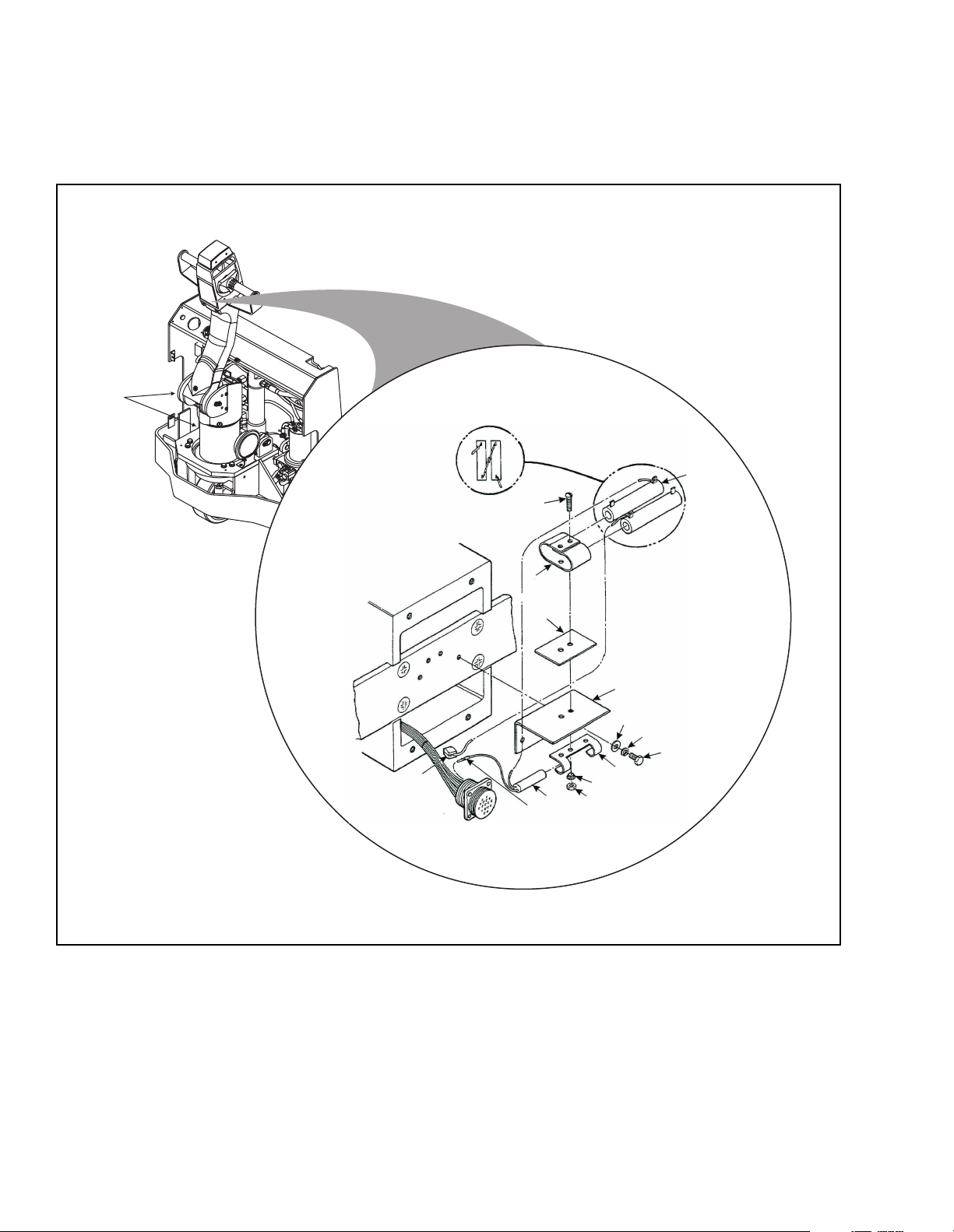
7-15. OPTIONAL EQUIPMENT
7-15.1 Cold Conditioning
16
2
3
4
5
15
13
14
Figure 7-15. Cold Conditioning Parts
12
11
6
7
8
9
10
I-7060
7-32 PPT0104-901336
Page 99

Index
No.
1 1 056491 Decal, Cold Conditioning
2 2 018909 10 0hm, 20 Watt Heat
3 2 068186 Screw
4 1 400544 Bracket, Resistor Mounting
5 1 018214 Insulator
6 1 402829 Bracket
7 2 077007 Washer
8 2 077204 Washer, Lock
9 2 072400-01 Screw
10 1 400044 Bracket, 1
11 2 403372 Insulator
12 2 059632 Nut, Lock
13 1 020736 Switch, Thermal
14 1 005643 Terminal, Contact Pin
15 1 005649 Splice
16 3 020799 Switches, Micro, Sealed
*17 A/R 055750 Grease
**18 A/R 055753 Grease
*19 A/R 055779 Hydraulic Oil
**20 A/R 055784 Hydraulic Oil
*21 A/R 055780 Transmission Oil
**22 A/R 055790 Transmission Oil
Qty. Part No. Description
* For intermittent operation below 32º F.
** For continuous operation below 32º F.
PPT0104-901336 7-33
Page 100

NOTES:
7-34 PPT0104-901336
 Loading...