


WiFi+GSM+RFID Smart Alarm System
User Manual
When designing, this system be added many amazing & practical
new features, to make sure a better smart life.

Key Features
1. Pure WiFi version, WiFi+GSM version optional.
2. Android & iOS APP operation. User can do all settings via APP.
3. Support working with WiFi camera. The App integrated the IP camera's to realize the video record, send pic to user Email when
system alarm.
4. Support 10 remote controls, 24 wireless + 4 hardwired sensors.
5. Zone 1 to 16 can be customized the SMS text message content.
6. A powerful 20 slaves wireless smart home control lighting, appliances etc.
7. App detection system per 4 hours: AC power OK or not; system ARM OR DISARM. Accessories power lower or not; connect to panel or not.; Zone
has accessories or not... Check the all system clearly, get system status in time.
8. Support ADEMCO Contact ID Protocol. It can work with CMS (Central Monitor System).
9. Delay Alarm/External & Internal siren On/Off for any zone.
10. Low-voltage sensor/sensor-lost be monitored.
11. RFID tag to Arm/Disarm (optional)
Technical Information
1. Power supply: input AC=100~240V, output DC=12V
2. Static current: <50mA (when not in charging, excluding wired detectors)
3. Alarm current: <120mA (excluding wired siren)
4. GSM transmission power: 2W
5. WiFi frequency: 2.4G, built-in wireless internet protocol IEEE802.11b/g and TCP/IP protocol stack
6. WiFi receiving sensitivity: -86dbm; Emitting power: 18dbm
7. GSM frequency: 850/900/1800/1900MHz
8. Back-up battery: 3.7V/800mA; Standby time: 8 hours; Full charge time: 12 hours
9. Wireless receiving distance: >100 meters (open space)
10. Wireless transmission distance: >100 meters (open space)
11. Working condition: Temperature -10°C~70 °C, RH 5%~95%
1

Zones’Attribute Definition:
Zones’Type: 1 Defend Line, 2 Defend Line, 24-Hour defend Line
Defence Line 1: Which must pass Door window, balcony and boundary etc, which consists of wireless Door Sensor, Wireless Motion Sensor.
Defence Line 2: Which must pass Saloon, Lobby, Apartment and Living-Room etc. Which consists of Wireless Wide-Angle Motion Sensor.
24-Hours Defend Line: 24-Hour zones, This attribute can not be modiÞed. In arm or disarm or stay mode, once the sensor in these zones be
triggered, system will alarm immediately, But not drive Siren. Which Consists of SOS Button, Wireless Gas Alarm, Wireless Somke Alarm.
Font Panel View
LCD Display
UP
Left
Right
Down
Conteol home ap pli anc es
Call/#Confi rm
Set/Exit
FRID
Away Arm
Home/Stay Arm
Disarm
SOS/Delete
2

Back Panel View
Button
Cable Slot
DC 12V input jack
Button 12V outp ut
(A: Arm disarm; S: SMS)
J12
I/O connector
ON OFF
-BELL+ 34 33 3 2 31 -12V+ S+GND A+ NO COM
Wired Siren
S3
WiFi SET/Reco ver y
SIM Card Slot
Wired Connection
3

Arm/Disarm System
Notice
“xxxx” is the current user code, default user code is “1111”, and default
admin/installer code is “1234”. The system is working with separate wireless
LCD/LED keypads, for activate and deactive operation, please refer to manual
of wireless keypad.
Basic Alarm Setting
Enter into Setting Status
When system is in Disarm status, push then input admin code,
default “1234”, press “OK” to enter into setting status.
System time setting
When system is in setting status, choose “Time Setting” to modify
the current time. The time will back to default automatically once
the alarm system is complete OFF.
Activate Away Arm
In keypad, touch to activate Away Arm.
Remotely via SMS, send SMS content: xxxx+A0
Remotely via phone, make phone call to alarm system, after pick up, input xxxx#, you
will hear "di" sound, press 1 to activate the Away Arm.
Activate Stay Arm
In keypad, touch to activate the Stay Arm
Remotely via phone, make phone call to alarm system, after pick up, input xxxx#, you
will hear "di" sound, press 2 to active the Stay Arm
Disarm
In keypad, touch then, input xxxx+OK
Remotely via SMS, send SMS content: xxxx+A2
Remotely via phone, make phone call to alarm system, after pick up, input xxxx#, you
will hear “di” sound, press 3 to disarm.
4
Time Setting
Phone No.Setting
Time Setting
9/11/2013
Time Setting
04:54:08
Time Setting
THU
Press “OK” to select and “ ” to delete the default date, then enter
with new time (XXhours, XXminute, XXsecond). Do same procedure
for date. (XXDate, XXMonth, XXYear) Press “OK” and “◀▶” select the
week, press “OK” to confiall settings.
Alarm Receiving Phone Number
This alarm system can totally preset up to 5 personal emergency
phone numbers for alarm receiving.

Time Setting
Phone No.Setting
Push “ ◀▶” toselect the Alarm Call or Alarm SMS, then push “OK”, you can input the number.
1st and 2nd group for setting Alarm SMS, 3rd group for setting Alarm SMS or Alarm Call, 4th&5th groups fot setting Alarm Call.
Phone Groups 1
Alarm Call >
Phone Groups 1
13800138000
·
Basic Alarm Setting
Push “ ” you can delete the existing phone number.
You need touch “Ok” to save,and navigate into next phone number setting menu.
Notice: Maximum digitals fot phone number input is 15.
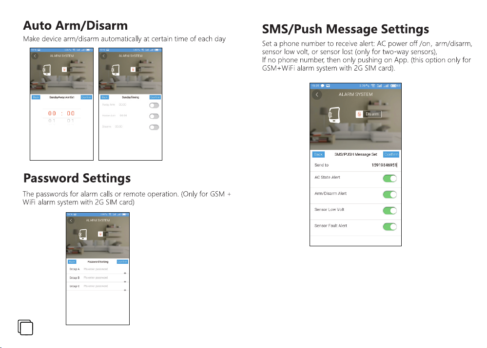
SMS Number for System System Status
The alarm system can preset one phone number for receiving SMS report of system’s status, including AC
power recover, Arm/Disarm, Host Low Voltage,Sensor Low Voltage.
SMS Setting
Record
Push“ ”to delete exist phone number, enter new mobile phone number. Touch “OK” to save the phone number, it will navigate to event report
selection. Touch “◀▶” to select enabled or disable the event report. AC power recover means when external enlectricity is recover, the alarm system
will send SMS. Arm/Disarm SMS means when alarm system is Armed or Disarmed, the system will send SMS. Host Low Volt means when backup
battery power is low, the system will send SMS. Sensor Low Volt means when battteries run out in wireless sensors, it will send SMS.
SMS Phone No.
13800138000
Host Low Volt
OFF >
AC Power Recover
OFF >
Sensor Low Volt
OFF >
Arm/Disarm SMS
OFF >
5

Basic Alarm Setting
Record Voice Memo
The system allows user to record up to 10 seconds voice memo. When
alarm phone call is picked up, press “5” to listen the voice memo.
SMS Setting
Record
Recording Time
10
Record
OFF >
Basic Alarm Setting
Arm Delay
Alarm delay
Push “ ” to delete exist data, and input new seconds (e.g 10). lt accpet
time between 00-59. push“OK” to save.
Notice: You need go to [Zone attribute] to enable which zones are belong
to this function, therefore it can work.
Siren Setting
It allows siren time setting for each zone. The siren time can be set from
00-59 minutes. User can choose whether use built-in siren or not.
Alarm Delay
10
Push “◀▶” to choose “On” torecord voice, and push “OK” to start voice
recording.
Arm Delay/Exit Delay
The Arm delay or exit delay can allow user to exit protected area before
system is Armed. The time is adjustable from 00 to 59 seconds.
Arm Delay
Alarm Delay
Push “ ” to delete default data, and enter new time. push “OK” to save.
Alarm Delay/Entry Delay
The alarm delay or entry delay can allow user to set alarm delay zones
before system set alarm off. This allow user enter into specific detection
area to disarm the system without triggering alarm.
Arm Delay
10
6
Siren Setting
Tone Setting
Siren Time
01
Push “ ” to delete the zone number, and input new zone number from
00-34. Touch “OK” to save
Push “ ” to delete the siren time, and input new siren time, “00” means
disable. Default value is 01
Push “◀▶” to choose “On” to enable built-in siren, and touch “OK” to save.
Zone No.
00
Built-in Siren
On >

Basic Alarm Setting
Tone setting
Tone setting means the alarm system will make “beep” sound, when
detects system event, such as telephone line cut, Arm/Disarm,
Temperature Alert.
Siren Setting
Tone Setting
Push “◀▶” to choose “OK” to save
Call in Setting
The system can receive the phone call via GSM. It allow user to set the
ring times from 1 to 9. When the ring time reach to preset times, it will
pick up the phone call for remotely control
Call in Setting
Program&Delete
Push “ ” to delete exist data. It accpets ring time between 1-9. Push
“OK” to save.
Program&Delete
Use this function to program/delete wireless sensors and accessories
(remote keyfob,wireless LED/LCD keypad). The wireless zone number is
from 00-30. Zone 00 is for programming wireless remote keyfob or
leypads.
Arm/Disarm Tone
Off >
GSM Call in Tone
3
Arm/Disarm Beep
Off >
Basic Alarm Setting
Push “ ” to delete the zone number, and input new zone number from
00-30 and push “OK”. push “ ” to choose [program], then push “OK”,
the LCD will display [programming]. Trigger the wireless sensors for two
times, the LCD display [Success], push “OK” to save, you can continue to
enroll more sensors.
Push “ ” to delete the zone number, and input new zone number from
00-30 and push “OK”. push “ ” to choose delete, the LCD will display
[Success], push”OK” to save. This will erase the current sensors in the zone
from the alarm system.
Zone Attribute
The system has advanced zone attribute, it allow user to choose each of
attribute for the zones, it helps user to customize the system, which can
be more suitable fot speciÞc installation. Ensuring the zones with correct
attribute, therefore sensors can work properly.
Zone Attribute
Upload
Activate >
0 Defence Line >
Zone Chime Off >
Smart Sensor Off >
Zone No
00
00Help >
Alarm Delay Off >
Call in Setting
Program&Delete
Program
Delete
Zone No
00
Success
7

Basic Alarm Setting
Push “ ” to delete the zone number, and input new zone number from 00-30. push “OK” navigate to next menu. push “OK” you will navigate to last
level menu.
Bypass Sensor: push “◀▶” to choose “Disable” to deactivate/bypass this zone.
Zone type: push “ ” to choose defense line, push “◀▶” to change the value from including 0, 1, 2.
Sensor type: push “ ” to choose sensor type, push “◀▶” to change the sensor type.
Alarm Delay: push “ ” to choose alarm delay off, push “◀▶”to enable or disable the alarm delay.
Zone Chime: push “ ” to choose zone chime off, push “◀▶” to enable or disable this function.
Smart Sensor Off: push “ ” to choose smart sensor off, push “◀▶” to enable or disable this function.
Notice:
[0 Defense line] means Þre, panic alarms, which are belong to 24 hours emergency zone. It will trigger the alarm system, even the system in disarm
status.
[1 Defense line] means perimeter protection, which is belongto perimeter zone. lt will work when alarm system in both AwayArm and Home Arm
modes.
[2 Defense line] means interior protection, which is belong to motion zone. The sensors in this zone will be activated when system is in AwayArm
mode, but will be de-activated, when system in Home Arm/Stay Arm mode.
8
Zone Nu mber
00
01~05
06~14
15~24
25~28
29~32
Zone Type
N/A
Emergency Zone
Perimeter Zone
Motion Zone
Hardwired Z one
FRID
Sensor Type
Wireless Remote Keyfob
Wireless Sensors
Wireless Sensors
Wireless Sensors
Sensors

Basic Alarm Setting
Default zone number for sensor and keyfob for standard alarm kit
Wireless Remote
00 11 21 02
Upload
The system can either be used as self-monitoring system or monitored by security company. lt's compatible with ADEMC0 Contact ID protocol for
alarm monitoring. lf you want to link the alarm system into alarm monitoring center, you need to do this operation. Moreover, the system not only
upload alarm information, but also upload system's status to central monitoring station.
Zone Attribute Center Phone No. User Code Upload status
Upload 911 0001 Off
Push “ ” to delete exist number, and input new alarm monitoring
centre number. Push “OK” to save, then navigate to next level menu,
push “ ” to delete default user code, and input your user code, push
“OK”to save, then navigate to next level menu, touch " " to choose
disable or enalbe upload status, push “OK” to save, navigate to next
status selection menu.
AC Fail Upload Host Low Volt Sensor Low Volt Manual Test
Off > Off > Off > Off >
Wireless Door Sensor
Wireless PIR motion
Period Test
00000
Wireless Smoke
9

Basic Alarm Setting
User Code
Navigate to this menu, user can modify the user code. The user code
with authorization for Arm/Disarm the system via keypad, SMS, phone
call, mobile applications (APP). The default user code is “1111”
Password Setting
Pin Setting
Admin Code
Navigate to this menu, user can modify the admin code. The admin code
with authorization for programming the system. The default admin code is
"1234"
Password Setting
Pin Setting
Resrt
Navigate to this menu, user can reset the alarm system. The system will
reset to factory status. If user have done wrong programming, can not be
solved, then you can use reset function. It will erase all the user's
programming data.
Password Setting
####
Pin Setting
####
push “ ”to delete the default time, and input new time e.g: 1200, push
“OK”to save and next time setting, it will navigate next day for auto
arm/disarm setting.
Notice :
The time format should be 12:00, hours then minutes.
Wrong time input can not be saved.
How to use 12V relay Output
User arm the host by remote controller or host‘keyfob, the host also turn
on 12V output at the same time; When Disarm, also turn off 12V output
simultaneously. This funcation is convenient to allow user to
corresponding appliances ( A Wire ports) .
The user also use the funcation by SMS under disarm, send 1111+C002
message to alarm, meaning turn on 12V relay , if sending 1111+C003
message to alarm, means turn off 12V reply (S Wire ports)
appliances must be 12V Voltage
Reset
Auto Arm/Disarm
Auto Arm/Disarm
This function can make the alarm system automatically Arm/Disarm in
preset time for everyday.
Reset
Auto Arm/Disarm
Reset
Off >
SUN
--:-- Away Arm
10

How to use lntelligent home appliances
When user is in the office, on the shopping malls or outside. who wants to turn on the light and other corresponding appliances at home, the host
can achieve what you want by remote SMS When user is at home who can operate the funcation by SMS or by host keyfob. The host which is with 8
wireless switch control function. Operation method is
Remarks: The funcation must match with wireless socket
SMS conmmand:
User Password+P11 means turn on No. 1 switch; User Password+P10 means turn off No.1 switch (Press host keyfob +11 turn on +10 turn off)
User Password+P21 means turn on No. 2 switch; User Password+P20 means turn off No.2 switch (Press host keyfob +21 turn on +20 turn off)
User Password+P31 means turn on No. 3 switch; User Password+P30 means turn off No.3 switch (Press host keyfob +31 turn on +30 turn off)
User Password+P41 means turn on No. 4 switch; User Password+P40 means turn off No.4 switch (Press host keyfob +41 turn on +40 turn off)
User Password+P51 means turn on No. 5 switch; User Password+P50 means turn off No.5 switch (Press host keyfob +51 turn on +50 turn off)
User Password+P61 means turn on No. 6 switch; User Password+P60 means turn off No.6 switch (Press host keyfob +61 turn on +60 turn off)
User Password+P71 means turn on No. 7 switch; User Password+P70 means turn off No.7 switch (Press host keyfob +71 turn on +70 turn off)
User Password+P81 means turn on No. 8 switch; User Password+P80 means turn off No.8 switch (Press host keyfob +81 turn on +80 turn off)
11

Alarm Handle for User
Receiving Alarm SMS
Once an alarm occurs, the system will send SMS as long as user choose for alarm SMS notification.
The system will send SMS with below content
(0001)Alarm System: 11 Zone Door Sensor Alarming
Inquiry System’s Status
The system allow user to inquiry the system’s status, send “User code + C” text message to alarm system, alarm will reply text message inform you
whether it’s Armed or Disarmed
12

Alarm Handle for User
Receiving Alarm Phone Call
Once an alarm occurs, the system will make phone call as long as user choose for alarm call notiÞcation.The alarm systems support remotely control
via phone call, including Away Arm/Stay Arm/Disarm, Onsite voice monitoring, listen voice message, talk back, two-way intercom, recording meno.
When pickup alarm phone call, you will hear the siren sound, after the replay, you can:
Press “1” on the phone to Away Arm (lt will hang up immediately, system will be Away Armed)
·
Press “2” on the phone to Stay Arm (lt will hang up immediately, system will be Stay Armed)
·
Press “3” on the phone to Disarm (lt will hang up immediately, sytstem will be Disarmed)
·
Press “4” on the phone to listen onsite voice (lt will hang up, after 20 seconds delay)
·
Press “5” on the phone to listen voice memo
·
Press “6” on the phone to talk back (fixed phone number doesn't support this function)
·
Press “8” on the phone to begin two-way intercom (except fixed phone number)
·
Press “*” on the phone for alarm conÞrmation, it will hang up, stop to dial phone call
·
13

How to Use Wireless Keyfob
Working LED
Program&Delete
Go to [Program&Delete] for programming wireless remote keyfob, program
keyfobs in sequence into zone 00
Disarm
Stay Arm
Arm/Disarm/SOS
Away Arm the system:
Stay Arm the system:
Disarm the system:
Trigger SOS alarm:
14
Away Arm
SOS
Call in Setting
Program&Delete
Press “ ” to choose "Program", then press "OK" to conÞrm, the LCD display ◀▶
[Programming], Now press the “ ”button for two times, the LCD will display
[Success], then touch "OK" to save.
Call in Setting
Program&Delete
Press “ " to choose "Delete", then press "OK" to conÞrm, the LCD will display ◀▶
[Success], then to press "OK" to save.
Zone No.
00
Zone No.
00

How to Use Wireless Door Sensor
Introduction
Wireless door sensors or entry point sensors are the most reliable intrusion detection device for perimeter protection. The door sensor is adopting
reed switch theory, it consists of wireless transmitter and magnetic two parts. When two parts sperate maximum 1 cm, the sensor will send alarm
signal to ala rm system.
LED lndicator
RF transmitter
Notice:
The door sensor in the package may differ from manual.
Panic button
Magnetic
Tamper Swtich
Battery
Program&Delete
Go to [Program&Delete] for programming wireless remote keyfob,
program keyfob in sequence into zone 06~14.
Press “◀▶" to choose "Program", then press "OK" to confirm, the LCD will
display [Programming].
Now separate door sensor for two times, the LCD will display [Success],
then press "OK" to save.
Call in Setting
Program&Delete
Press “◀▶” to choose “Delete” , then press “OK” to confirm, the LCD will
display [Success]
Zone No.
01
15

How to Use Wireless Door Sensor
Installation
Remove the insulating protect on battery.
·
Mount the transmitter on the door frame and the magnet on the door.
·
Make sure that the magnet is always on the right side of the transmitter.
·
Make sure that the magnet will not be more than l cm from the transmitter.
·
Attach the transmitter and the magnet with dou ble-sided tape or the screw.
·
Avoid placing the detector in areas with la rge-metallic structu res or electrical installations such as boiler area or counters.
·
Technical lnformation
Working voltage: 1.5 Lr6
·
Static current: ≤30μA
·
Alarm current: ≤40mA
·
Emitting frequency: 433MHz/(868MHz optional)
·
Transmission distance: ≤100m(Open space)
·
Lifespan of battery: ≤12 months
·
Notice:
The door sensor in the package may different from manual. The specification will change, when use different model of wireless door sensors.
16

How to Use Wireless PIR Sensor
Introduction
PIR motion sensor is one of common intrusion sensor for instruction detection. It with advantages of large space protection, lowest ener 9V
consumption. It detects infrared energy changes which is caused by movement of human.
Program&Delete
Go to [Program&Delete] for programming wireless remote keyfob, program keyfob
in sequence into zone 15~24.
Press "◀▶ " to choose "Program", then touch "OK" to confirm, the LCD will display
[Programming].
Now trigger PIR sensor for two times, the LCD will display [Success], then touch
"OK" to save.
1.Wide angle fresnel lens
2.Alarm LED lndicator
3.Swivel Bracket
Call in Setting
Program&Delete
Press “ ” to choose “Delete”, then press “OK” to confirm, the LCD will display ◀▶
[Success], then press “OK” to save.
Zone No.
21
17

How to Use Wireless PIR Sensor
Installation
Due to the wide coverage angle and the swivel bracket, the motion sensor can easily be installed:
Indoor environment noly!
·
Wall mounted on the wall and sensor points to entry point of doors
·
Wall mounted on corridor to detect movement
·
Technical Information
Working voltage: 2x1.5V LR6
·
Static current: ≤50μA
·
Alarm current: ≤9.5mA
·
Detection angle: ≤110°
·
Detection distance: ≤12m
·
Emitting frequency: 433MHz/(868MHz optional)
·
Transmission distance: ≤100m (Open space)
·
Lifespan of battery: ≤12 months
·
Notice:
The PIR sensor in the package may different from manual. The specification will change, when use different model of wireless PIR sensor.
18

Hardwired Zone Connection
Hardwired Zone Connection
Maintenance and Care
This alarm system is a H i-Tech p roduct w ith o uts tan ding design and sophistica ted t ech nol ogy. an d shall be care ful ly.
To make the alarm to aperate for a long term s tab ly an d to prolo ng th e ser vice l ife. it's reco mmended that:
·
Try to put the alarm panel in a dr y an d wel l-v entilated location
·
Do not put the alarm pan el an d any w ireles s sen sar s in too cold, too hot or dusty plac es to p revent i t
·
from curta iling the service live s of electric parts and preventing the plastic s hel l from distor ting.
Do not put the alarm pan el an d any w ireles s sen sor s in low and too exposed places to p revent chil d ren
·
from touching them or the thieves f rom fi nd ing t hem
Reglar testin g is ne ces sar y for Þnding and reso lving prables in time.
·
Regular y che ck th e bat teries in all wire less sensors. To ens ure normal operatio ns of the system, replace
·
with new batter ies w hen ever you feel a sensor is not detecti ng properly.
19

APP Operation Instructions
20

21

22

23

24

25
26

27

28

29

30

31

32

33
 Loading...