

Page 1
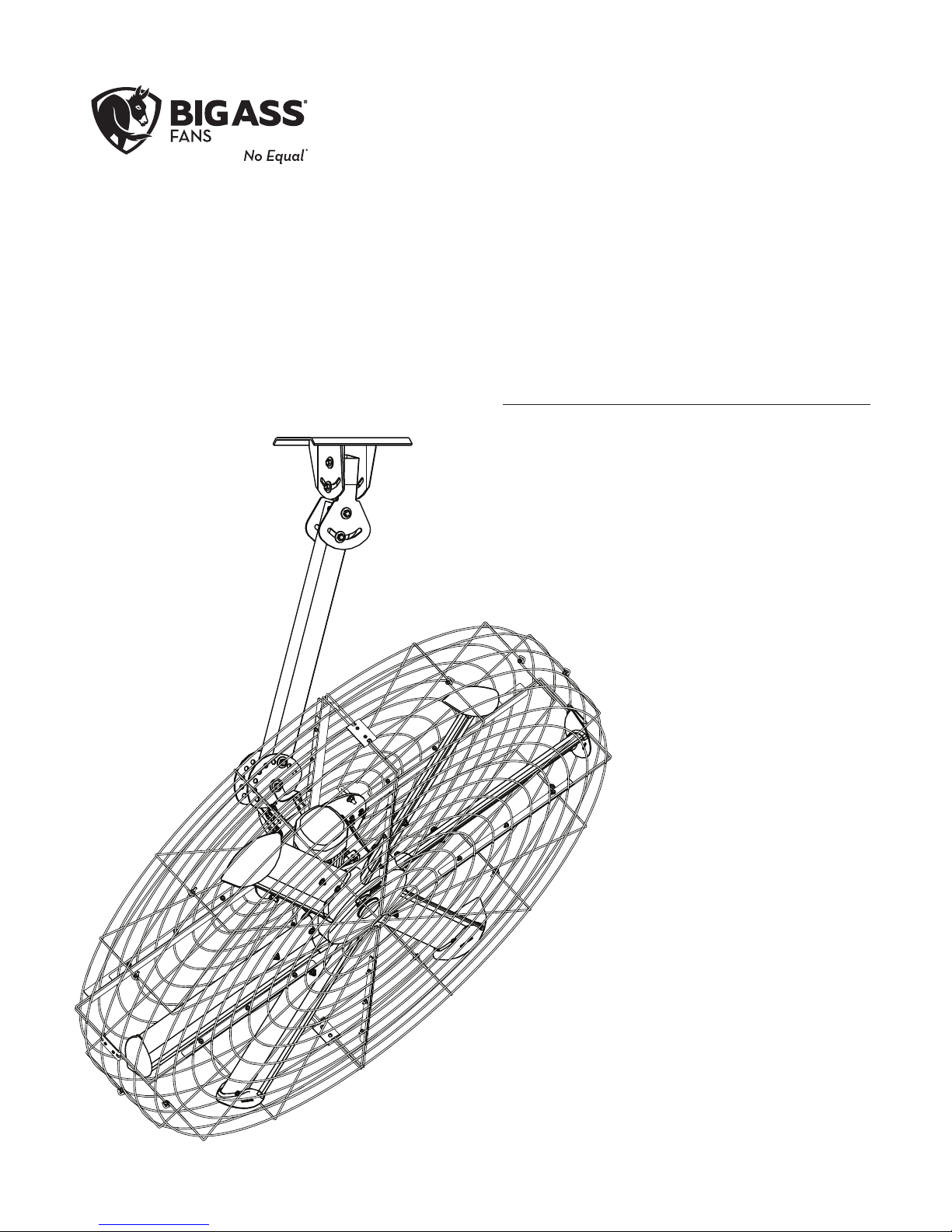
INSTALLATION
GUIDE
Pivot
For help, call 1-877-BIG-FANS
or visit www.bigassfans.com
Page 2
PRE-INSTALLATION CHECKLIST
Did a structural engineer approve the mounting structure?
See page 5 for Big Ass Fans approved mounting structures.
Are you familiar with the function and use of the safety cable?
See p. 14 for information on properly securing the safety cable.
Will the fan be installed so that the airfoils are at least 10 ft (3.05 m) above the floor?
Will the fan be installed so that the airfoils have at least 2 ft (0.61 m) of clearance from obstructions?
Will the fan be installed so that it is not subjected to high winds, such as from an HVAC system?
Install the fan so that it is ≥1x fan diameter away from a diuser if the fan is at same level or above
diuser. If the fan is below a diuser, install the fan so that it is ≥2x fan diameter from the diuser.
Will the distance between multiple fans be at least 2.5x the fans’ diameter when measured from
the centers of the fans?
If installing the fan on an I-beam, is the upper yoke the correct size?
See page 7 for more information on installing the fan to an I-beam.
If you ordered multiple fans, did you keep the parts for each fan together?
Do you have the correct power circuit for the fan controller?
See page 24 for information on selecting the correct circuit/fuse for the fan controller.
Customer Service: 1-877-BIG-FANS
(International: +1 859 233 1271)
Page 3
READ AND SAVE THESE INSTRUCTIONS
WARNING AND CAUTION SYMBOL
Indicates a hazard with a medium level of risk that could result in injury or death or damage
to property if not avoided.
ELECTRICAL WARNING SYMBOL
Indicates an electrical hazard with a medium level of risk that could result in death or serious
injury if not avoided.
Installation Guide
July 2016
Rev. N
Original English Instructions
This product was manufactured in a plant whose Management System is certified as being in conformity with ISO 9001.
Conforms to ANSI/UL STD 507: Electric Fans
Certified to CAN/CSA C22.2 No.113: Fans & Ventilators
Legal
Improper installation, delivery, or maintenance, including, but not limited to, any of the following actions by the customer or agent of the
customer will constitute a breach of and will void all warranties:
• Failure to follow the required installation procedures specified in this Installation Guide and in all other documentation supplied with
the fans and related equipment including documentation provided by the manufacturers of the individual fan and control components;
• Failure to follow all relevant codes and ordinances, including, but not limited to, the National Electric Code (United States), applicable
national and local electrical codes, and state and local building codes;
• Failure to follow electrical engineering industry standards regarding the approved method of installing solid-state electrical equipment
having the characteristics of the fans, the fan controls, and their related components, even if such standards are not specifically
referenced in any instructions or literature supplied by Big Ass Solutions or provided by manufacturers.
Pivot is a trademark of Delta T Corporation. All other trademarks used herein are the properties of their respective owners. No part of this
document may be reproduced or translated into a dierent language without the prior written consent of Big Ass Solutions. The information
contained in this document is subject to change without notice. For the most up-to-date information, see the online installation guide at
www.bigassfans.com.
www.bigasssolutions.com/patents ▪ www.bigasssolutions.com/warranties
Page 4

IMPORTANT SAFETY INSTRUCTIONS
WARNING—TO REDUCE THE RISK OF FIRE, ELECTRIC SHOCK, OR INJURY TO PERSONS, OBSERVE THE
FOLLOWING:
• The fan must be installed with mounting hardware that is marked to indicate suitability with this model.
Other mounting hardware cannot be substituted.
• Use this unit only in the manner intended by Big Ass Fans.
• Before servicing or cleaning unit, switch power o at service panel and lock the service disconnecting means
to prevent power from being switched on accidentally. When the service disconnecting means cannot be
locked, securely fasten a prominent warning device, such as a tag, to the service panel.
CAUTION: The installation of a Big Ass Fan must be in accordance with the requirements specified in this
installation manual and with any additional requirements set forth by the national electric code (NEC) and
all local codes. Code compliance is ultimately YOUR responsibility! Failure to comply with these codes could
result in personal injury or property damage.
WARNING: The fan controllers contain high voltage capacitors which take time to discharge after removal of
mains supply. Before working on the fan controller, ensure isolation of mains supply from line inputs at the fan
controller. Wait three minutes for capacitors to discharge to safe voltage levels. Failure to do so may result in
personal injury or death. Note: Darkened display LEDs are not an indication of safe voltage levels.
CAUTION: Exercise caution and common sense when powering the fan. Do not connect the fan to a damaged
or hazardous power source. Do not attempt to resolve electrical malfunctions or failures on your own. Contact
Big Ass Fans if you have any questions regarding the electrical installation of this fan.
WARNING: To reduce the risk of fire, electric shock, and injury to persons, Big Ass Fans must be installed with
Big Ass Fan supplied controllers. Other parts cannot be substituted.
CAUTION: When service or replacement of a component in the fan requires the removal or disconnection of a
safety device, the safety device is to be reinstalled or remounted as previously installed.
CAUTION: Do not bend the airfoils when installing, adjusting, or cleaning the fan. Do not insert foreign objects
between rotating fan airfoils.
WARNING: Stay alert, watch what you are doing, and use common sense when installing fans. Do not install
fans if tired or under the influence of drugs, alcohol, or medication. A moment of inattention while installing
fans may result in serious personal injury.
CAUTION: Do not operate fan with a damaged cord or plug. Return fan to an authorized service facility for
examination or repair.
CAUTION: Do not run cord under carpeting. Do not cover cord with throw rugs, runners, or similar coverings.
Do not route cord under furniture or appliances. Arrange cord away from trac area where it will not be
tripped over.
WARNING: To reduce the risk of electric shock, do not expose to water or rain.
Page 5

CONTENTS
Introduction
Pre-Installation
Mounting Structure:
I-Beam
Mounting Structure:
Bar Joists
Hanging the Fan
Thank You 1
About Big Ass Fans 1
About This Fan 1
Parts and Hardware 2
Tools Needed 3
Fan Diagram 4
Preparing the Worksite 5
Pivot Angle 6
1. Attach Upper Yoke (to I-Beam) 7
1. Select Proper Angle Irons 8
2. Pre-drill Angle Irons 9
3. Fasten Angle Irons Together (if Span is Longer Than 8 ft) 9
4a. Fasten Single Angle Irons to Roof Structure Mounting Points 10
4b. Fasten Double Angle Irons to Roof Structure Mounting Points 11
5. Attach Upper Yoke (to Angle Irons) 12
1. Attach Balance Joint (to Upper Yoke) 13
2a. Attach Extension Tube (to Balance Joint) 13
2b. Attach Extension Tube (to Upper Yoke) 13
3. Secure Upper Safety Cable 14
4. Attach Main Fan Unit (to Lower Yoke) 14
5. Attach Pivot Joint 15
6a. Attach Lower Yoke (to Pivot Joint) 15
6b. Attach Lower Yoke (to Extension Tube) 16
7. Attach Center Cap 16
Installing Airfoils
Installing Cage
Pivoting the Fan
Installing Guy Wires
Electrical Installation
1. Attach Winglets 17
2. Position Airfoils and Trim 17
3. Attach Airfoil Retainers 17
1. Attach Cage Bracket 18
2. Attach Upper Cage 18
3. Attach Lower Cage Sections (to Upper Cage) 19
4. Secure Lower Cage 19
1. Adjust Pivot Joint and Lower Yoke 20
2. Tighten Bolts on Upper Yoke and Balance Joint 20
1. Attach Eyebolt to Motor Frame 21
2. Attach Beam Clamp 21
3. Route Guy Wire through Gripple® 21
4. Install Remaining Guy Wires 22
Electrical Installation Safety 23
Electrical Installation Overview 23
Controller Storage 23
Page 6

Electrical Installation
Power Requirements for Fan Controllers 24
Mounting the Wall Controller 24
Input Power Conditioning 24
Conduit and Piping Guidelines 25
Power Wiring Guidelines 25
Grounding 26
Installing the Electronic Programming Module (EPM) 27
Wiring: Early Suppression Fast Response (ESFR) 28
Wiring: 100–125/200–250 V Single-Phase Fan Controllers 29
Wiring: 200–250 V Three-Phase Fan Controllers 30
Wiring: 400–480 V & 575–600 V Three-Phase Fan Controllers 31
Daisy Chaining 32
Wiring the Fan Motor: 9-Lead, Dual Voltage, Wye Motor Configurations 33
Operating the Fan Controller 34
Preventive Maintenance
Troubleshooting
Warranty Return
Instructions
Big Ass Fan Certified
Installers
Annual Preventive Maintenance 35
General Preventive Maintenance 35
Annual Maintenance Checklist 36
Troubleshooting 37
Acknowledgment & Return Instructions 39
Warranty Claim Form Instructions 40
Warranty Claim Form 41
Responsibility Agreement 42
Check-In Procedure 43
Close-Out Procedure 45
Page 7

INTRODUCTION
You’ve made a great choice! Big Ass Fans® are an ecient, cost-eective and seriously cool way to stay comfortable
and save energy all year long. More importantly, everything about your new fan—from the design of the motor to
the angle of the airfoils—is based on extensive research, testing, and innovative engineering. It will keep you and
your space comfortable for years to come.
Any questions or comments? We’d love to talk. Just call 1-877-BIG-FANS (1-877-244-3267) or visit bigassfans.com/
contact-us/.
About Big Ass Fans
Our provocative moniker originated with the massive overhead fans we perfected to bring comfort and energy
savings to large industrial buildings. Today, though, Big Ass Solutions is much more than industrial—and much
more than Big Ass Fans or Big Ass Light. Big Ass means quality, form, and function to solve problems in the built
environment. It means having a herd of engineers on sta and the world’s only R&D facility dedicated to testing air
movement on a grand scale. It means speaking to our customers directly to understand and solve their problems—
if they need air movement, we do it bigger and better. If they need light, we make incredibly bright, long-lasting
LEDs. But mostly it means an insatiable drive to improve, engineer, design, test, re-engineer, re-design, and re-test
until we get it just right. That’s why there’s No Equal
™
.
About this fan
Fan
diameter
6 ft
(1.8 m)
* With 3 ft (0.9 m) extension tube.
Motor
size
1.0 hp
(0.75 kW)
RPM @
180 RPM
60 Hz
Airfoil
length
28 in.
(71 cm)
Fan
weight*
207 lb
(90 kg)
Cage
diameter
74.5 in.
(189.2 cm)
Voltage and
Phase
100–125 V, 1 Φ 20 A 11.0 A
200–250 V, 1 Φ 15 A 5.5 A
200–250 V, 3 Φ 10 A 3.2 A
400–480 V, 3 Φ 10 A 1.6 A
575–600 V, 3 Φ 10 A 1.3 A
Minimum
circuit
size
Maximum
full load
current
WWW.BIGASSSOLUTIONS.COM © 2015 DELTA T CORP. ALL RIGHTS RESERVED.
1
Page 8
PARTS AND HARDWARE
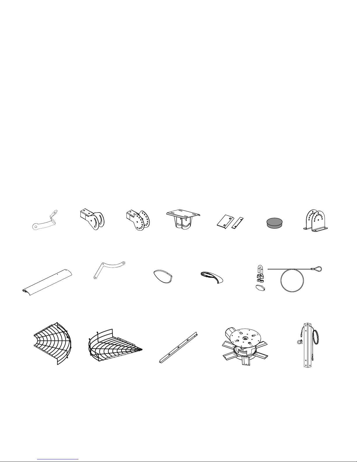
The fan and controller are shipped in one large box. The fan cage is shipped in a separate smaller box. If you
ordered multiple fans, be sure to keep the components of each fan together.Note: Drawings are not to scale.
Hardware
Beam Clip Hardware
• (4) 1/2-13 x 2” Bolts
• (8) 1/2” Flat Washers
• (4) 1/2-13 Nylock Nuts
Main Fan Unit Hardware
• (4) 1/2-13 x 1 3/4” Bolt
• (8) 1/2” Flat Washers
• (4) 1/2-13 Nylock Nuts
Cage Hardware
• (56) 1/4-20 x 1” Flange Bolt
• (56) 1/4-20 Flange Nut
Parts
(2) Mount
Brackets
Balance
Joint
Balance/Pivot Hardware
• (4) 1/2-13 x 5” Bolts
• (8) 1/2” Flat Washers
• (4) 1/2-13 Nylock Nuts
Winglet Hardware
• (6) 10-24 x 1/2” Bolts
• (6) 10-24 x 3/4” Barrels
Cage Clip Hardware
• (4) Cage Clip (Outer)
• (4) Cage Clip (Inner)
Pivot
Joint
Extension Tube Hardware
• (2) 1/2-13 x 4-1/2” Bolts
• (4) 1/2” Flat Washers
• (2) 1/2-13 Nylock Nuts
Guy Wire Hardware
• (1) 3/8-16 x 1” Eyebolt
• (2) 3/8” Washer
• (1) 3/8-16 Nylock Nut
• (8) 10-32 x 1/2” Flange Bolt
• (8) 10-32 Flange Nut
Upper
Yok e
(2) Beam Clip
& Spacer
Lower Yoke Hardware
• (2) 1/2-13 x 4-1/2” Bolts
• (4) 1/2” Flat Washers
• (2) 1/2-13 Nylock Nuts
1
• (1) 1/4” Beam Clamp
• (1) 1/4-20 x 1” Eyebolt
• (1) 1/4-20 Hex Nut
Center
Cap
Lower
Yok e
(6) Airfoil (6) Airfoil
Retainer
(4) Upper Cage
Section
1. Guy wires are designed to constrain fan’s lateral movement and are only included in some fan packages. Big Ass Fans recommends using guy wires if
the fan’s extension tube is 4 ft or longer, if the fan is pivoted, if the fan is exposed to high winds, or if the fan is close to any building fixtures. Guy Wire
hardware is bagged separately.
2. Safety cable is attached to extension tube.
3. Included in main hardware bag.
2
(4) Lower Cage
Section
WWW.BIGASSSOLUTIONS.COM © 2015 DELTA T CORP. ALL RIGHTS RESERVED.
(6) Winglet (6) Inner
Trim
(4) Guy Wire, Gripple,
Carabiner, & Wire Rope
(4) Cage Bracket Motor Unit Extension Tube
1
Page 9

TOOLS
Big Ass Fans recommends gathering the following tools prior to beginning installation.
Electrical Installation
☐ Phillips and Flat Head Screwdriver
☐ 7 mm Nut Driver
☐ 5/16” Nut Driver
☐ Pair of #10 to #14 AWG Strippers
☐ Pair of Medium Channel Locks
☐ Multimeter
☐ Blue (14-18 AWG) #8 Stud Ring Terminals
Mechanical Installation
☐ Standard Wrench Set
☐ Standard Socket Set with Ratchet
☐ Torque Wrench Capable of 40 ft⋅lb (54.2 N⋅m)
☐ Phillips and Flat Head Screwdriver
WWW.BIGASSSOLUTIONS.COM © 2015 DELTA T CORP. ALL RIGHTS RESERVED.
3
Page 10
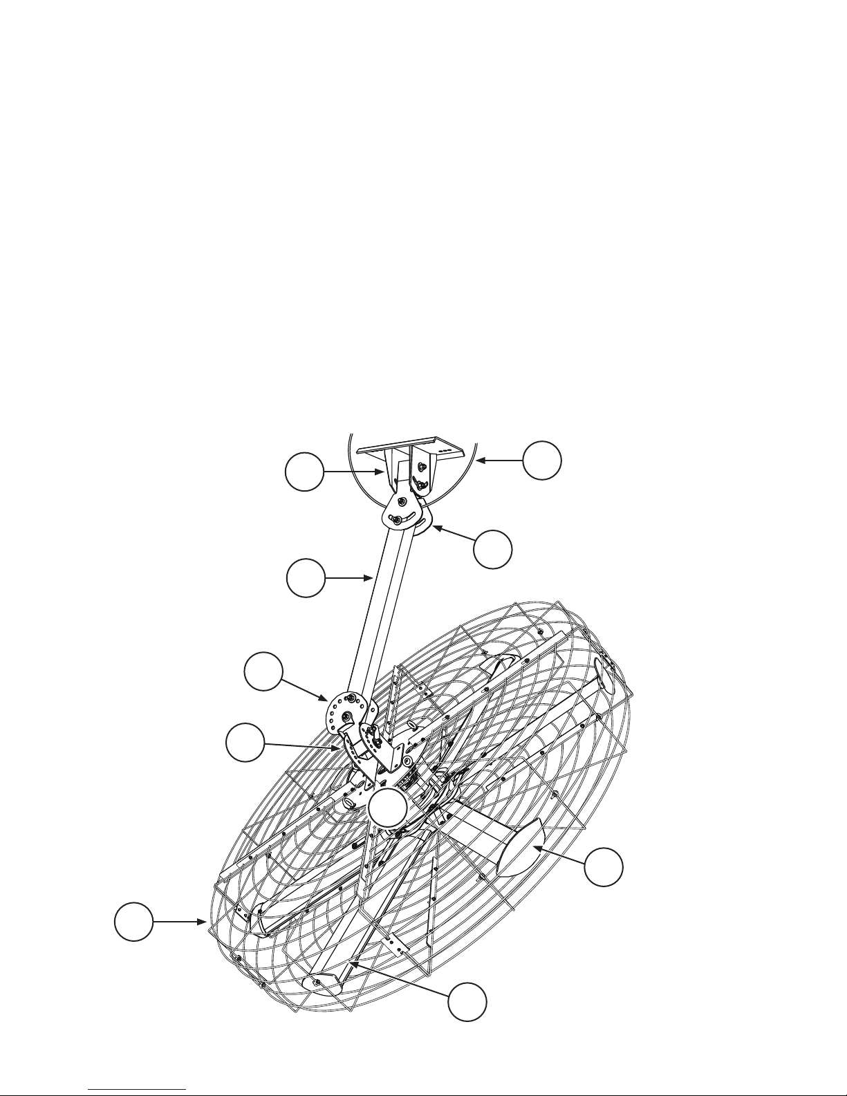
FAN DIAGRAM
A. Safety Cable. A redundant safety feature that secures the fan to the mounting structure. The safety cable must
be installed with the fan.
B. Upper Yoke. Secures the fan to the mounting structure and allows the fan to adjust its center of gravity.
C. Balance Joint. Allows the fan to adjust its center of gravity. If the fan is not going to be pivoted, it is not
necessary to install the balance joint.
D. Extension Tube. Extends the fan from the ceiling.
E. Pivot Joint. Allows the fan to be pointed in dierent directions. If the fan is not going to be pivoted, it is not
necessary to install the pivot joint.
F. Lower Yoke. Allows the fan to be pivoted in dierent directions. Connects main fan unit assembly to mounting
assembly.
G. Motor. See p. 1 for more information.
H. Winglet. Improves fan eciency and air distribution.
I. Airfoil. Provides air movement. The unique patented design provides ecient and eective air movement.
J. Cage. Protects the fan assembly.
F
B
A
C
D
E
G
J
4
WWW.BIGASSSOLUTIONS.COM © 2015 DELTA T CORP. ALL RIGHTS RESERVED.
H
I
Page 11
PREPARING THE WORK SITE
Before beginning installation, review the mechanical and electrical installation guidelines below.
Mechanical Installation
• A scissor lift or other suitable means for lifting the weight of the fan and at least two installation personnel will
be required.
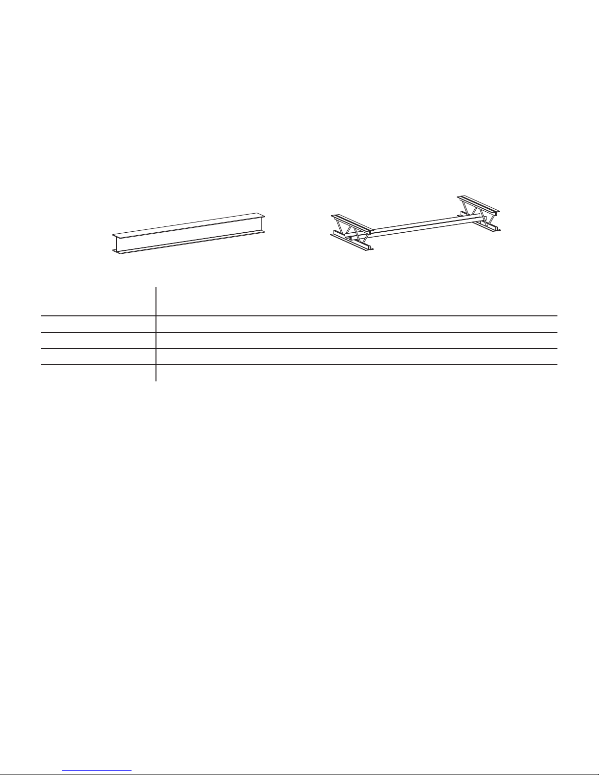
• Big Ass Fans can only be hung from an I-beam or angle irons. Do not mount the fan to single purlins, trusses, or
bar joists. Consult a structural engineer for installation methods not covered in this manual.
Angle Iron
• Adhere to the safety requirements in the table below when selecting the fan location.
Clearance
Airfoil height
HVAC equipment
Fan spacing
Radiant/IR heaters
≥ 2 ft from all fan parts. The fan installation area must be free of obstructions such as lights,
cables, sprinklers, or other building structure.
≥ 10 ft above the floor
≥ 1x fan diameter if at same level or above diuser. ≥2x fan diameter if below diuser.
2.5x fan diameter, center-to-center
See the manufacturer’s requirements for the minimum clearance to combustibles.
I-Beam
Electrical Installation
• To reduce the risk of electric shock, wiring should be performed by a qualified electrician! Incorrect assembly
can cause electric shock or damage the motor and the controller!
• The installation of a Big Ass Fan must be in accordance with the National Electrical Code, ANSI/NFPA 70-2011,
and all local codes.
• Refer to the Electrical Installation section in this manual for acceptable unshielded and shielded cable types.
• MC cable (stranded or solid core) may not be used for fan output/motor input leads.
• The motor leads from the fan control to the fan cannot be greater than 400 ft (121.9 m).
• The fan must be visible from its controller unless a suitable means of disconnect is used at the motor.
• The output/motor leads cannot share the same conduit or piping as the AC power supply. AC supply feeds for
one fan controller may share the same conduit with AC supply feeds for one or more controllers.
• AC supply feeds for a fan controller and the output/motor leads for the same fan may not share a conduit.
• AC supply feeds for one fan controller may not share conduit with output/motor leads from one or more
controllers/VFDs.
• All unused conductors that share a conduit with the AC supply feeds must be grounded on both ends.
• Controller output/motor input leads may not share a conduit with any other controller’s output/motor leads.
• Controller output/motor input leads may not share a conduit with any other controller’s AC supply feed.
WWW.BIGASSSOLUTIONS.COM © 2015 DELTA T CORP. ALL RIGHTS RESERVED.
5
Page 12
PIVOT ANGLE
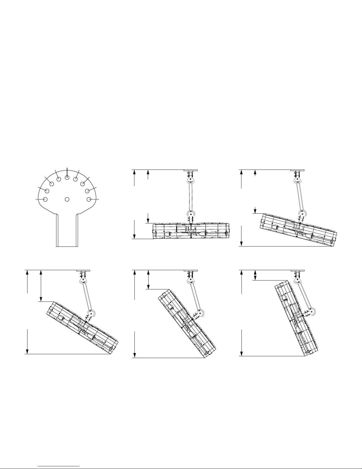
Pivoting the fan decreases the amount of clearance the fan has from the ceiling and the floor. Before installing the
fan, verify that it will have adequate clearance using the diagram below.
Observe the following safety measures when pivoting the fan:
• To pivot the fan at its maximum angle, a minimum extension tube length of 3 ft is recommended.
• The lowest moving part of the fan must be at least 10 ft (3.05 m) above the floor.
• After the fan is pivoted, there should be adequate clearance between the airfoils and any obstructions.
• Take special precaution to ensure that fan blades will be clear of safety cable and motor cable.
Pivot Angle Diagram¹
1
2
3
30’’
(76 cm)
85” (216 cm)
0
1
2
3
44
50” (127 cm)
70” (178 cm)
2 3 4
20’’ (51 cm)
30’’ (76 cm)
0 1
40” (102 cm)
80” (203 cm)
10’’ (25 cm)
90’’ (229 cm)
1. Measurements and angles will vary depending several factors including extension tube length and pivot configuration.
2. To estimate measurements for dierent extension tube lengths, add/subtract the dierence in length. For example, for a 2-ft extension tube, subtract 1 ft
from each measurement.
6
WWW.BIGASSSOLUTIONS.COM © 2015 DELTA T CORP. ALL RIGHTS RESERVED.
(with 3-ft extension tube²)
Page 13
MOUNTING STRUCTURE: I-BEAM
ATTENTION
Big Ass Fans can only be hung from an I-beam or bar joists. See the following page for bar joist mounting
instructions. Consult a structural engineer for installation methods not covered in this manual.
WARNING: The following instructions assume that the customer’s roof structure from which the fan will
be hung is of sound construction, undamaged, and capable of supporting loads of up to 645 lbs (293 kg).
It is the sole responsibility of the customer to verify that the roof structure is adequate for fan installation.
Big Ass Fans recommends consulting a structural engineer prior to fan installation.
CAUTION: It is not recommended to mount a Big Ass Fan from a fabricated I-beam.
CAUTION: Install the spacers only if the thickness of the I-beam flange exceeds 3/8” (1 cm). The mounting
holes on the spacer are closer to one side than the other. Make sure this side is facing the I-beam.
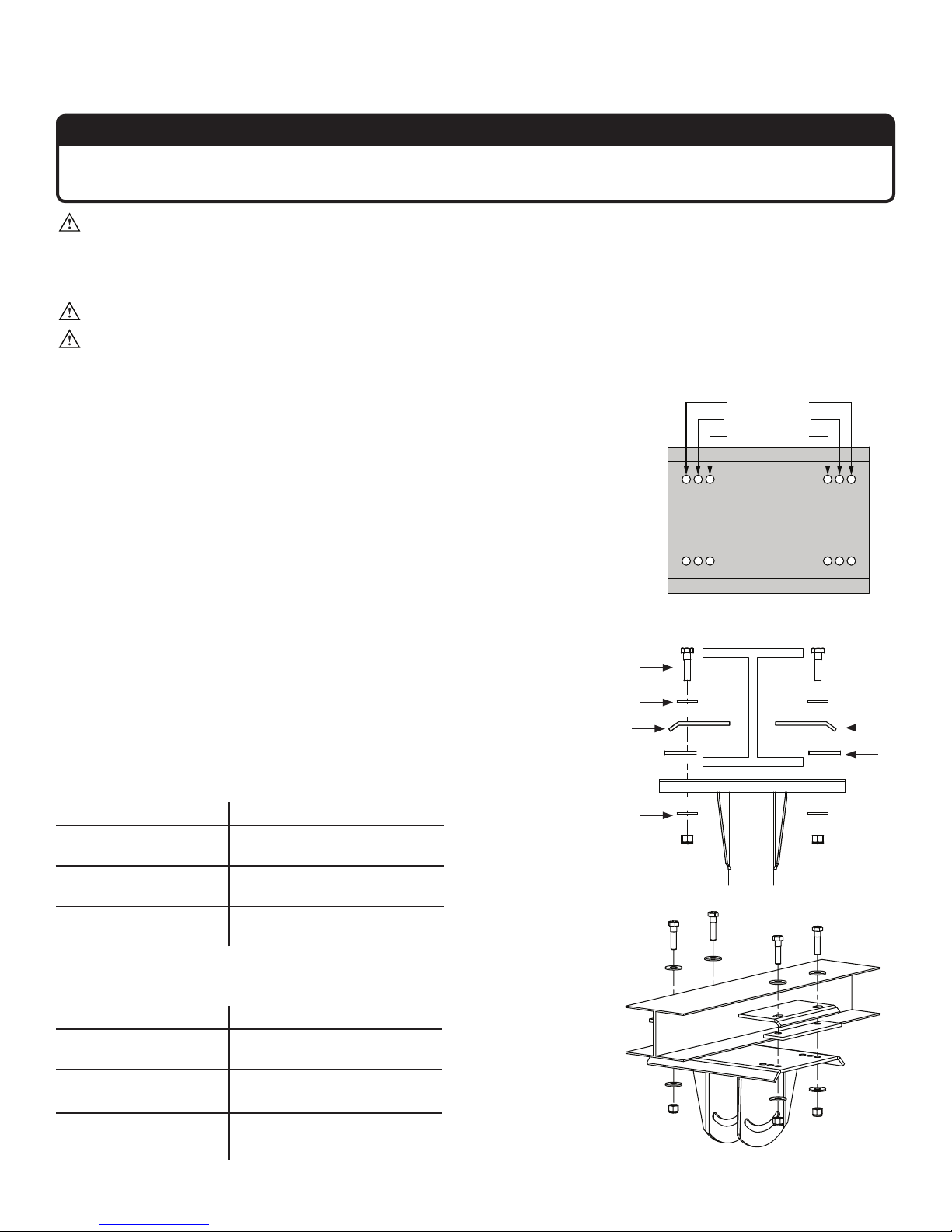
1. Attach upper yoke (to I-beam)
Measure the flange width of the I-beam from which the fan will be hung.
Consult the tables and diagram below to determine what size upper yoke
is included with your fan package. Select the upper yoke mounting holes
that match the flange width of the I-beam.
Secure the upper yoke to the I-beam with the Beam Clip Hardware as
shown. Tighten the bolts to 40 ft·lb (54.2 N·m) using a torque wrench
and 3/4” socket.
Proceed to “Hanging the Fan.”
Beam Clip Hardware:
a. (4) 1/2-13 x 2” GR 8 Bolt
b. (8) 1/2’’ Flat Washer
c. (4) 1/2-13 Nylock Nut
d. (2) Beam Clip
e. (2) Spacer
Small Upper Yoke
13-3/4’’ x 10” (349 mm x 258 mm)
I-Beam Flange Width Upper Yoke Mounting Holes
5” to 6-5/8”
(127 mm to 168 mm)
> 6-5/8” to 8-1/4”
(168 mm to 210 mm)
> 8-1/4” to 9-7/8”
(210 mm to 250 mm)
Inner holes
Middle holes
Outer holes
outer holes
middle holes
inner holes
Upper Yoke
(top view)
a
b
c
d
e
b
Large Upper Yoke
18-1/2’’ x 10” (470 mm x 258 mm)
I-Beam Flange Width Upper Yoke Mounting Holes
9-7/8” to 11-3/8”
(250 mm to 289 mm)
> 11-3/8” to 13”
(289 mm to 330 mm)
> 13” to 14-5/8”
(330 mm to 371 mm)
Inner holes
Middle holes
Outer holes
WWW.BIGASSSOLUTIONS.COM © 2015 DELTA T CORP. ALL RIGHTS RESERVED.
7
Page 14
MOUNTING STRUCTURE: BAR JOISTS
ATTENTION
If you are installing the fan to an I-beam and have attached the upper yoke, proceed to “Hanging the Fan.”
WARNING: The following instructions assume that the customer’s roof structure from which the fan will
be hung is of sound construction, undamaged, and capable of supporting loads of the fan and its method
of attachment. It is the sole responsibility of the customer to verify that the roof structure is adequate for
fan installation. Big Ass Fans recommends consulting a structural engineer prior to fan installation.
WARNING: Never use beam clamps when mounting the fan to angle irons! Beam clamps are only intended
for I-beam installations.
CAUTION: Do not install the fan from a single purlin, truss, or bar joist.
CAUTION: Unsupported angle iron spans should not exceed 12 ft (3.7 m).
CAUTION: The angle irons must be fastened to the roof structure at each end.
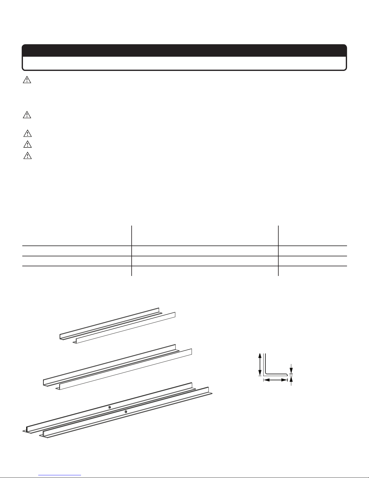
1. Select proper angle irons
Follow the table below when selecting angle irons for fan installation. Note: Angle irons and angle iron hardware
are not included with the fan.
Angle iron span
(between mounting points)
6 ft (1.8 m) or less 2.5” x 2.5” x 0.25” (6.4 cm x 6.4 cm x 0.6 cm) 2
over 6 ft to 8 ft (1.8 m to 2.4 m) 3” x 3” x 0.25” (7.6 cm x 7.6 cm x 0.6 cm) 2
over 8 ft to 12 ft (2.4 m to 3.7 m) 3” x 3” x 0.25” (7.6 cm x 7.6 cm x 0.6 cm) 4*
*Two pairs of angle irons. Pairs should be placed back to back and fastened in center (see step 3).
Minimum angle iron dimensions
(W x H x T)
Number of angle
irons needed
Angle Iron Side View
6 ft (1.8 m) or less
over 6–8 ft (1.8–2.4 m)
(see table for dimensions)
Height
Width
Thickness
over 8–12 ft (2.4–3.7 m)
8
WWW.BIGASSSOLUTIONS.COM © 2015 DELTA T CORP. ALL RIGHTS RESERVED.
Page 15
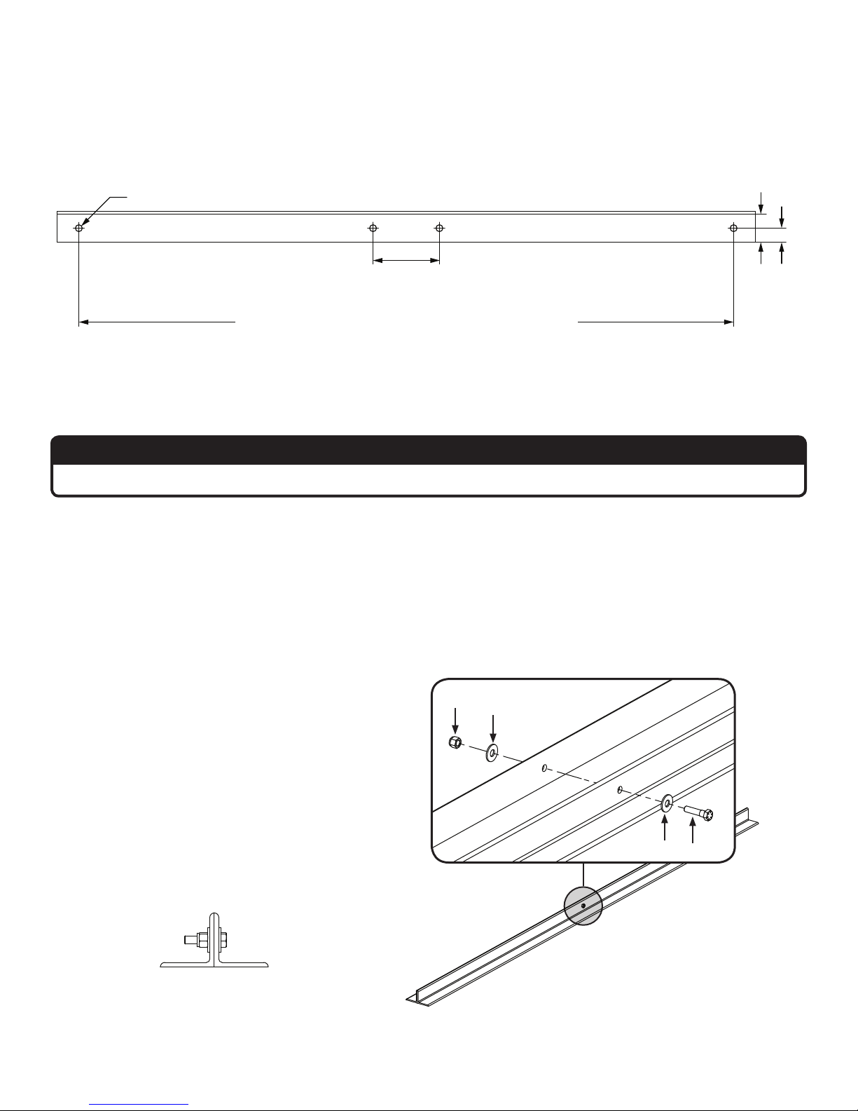
2. Pre-drill angle irons
Drill two Ø 9/16” (1.4 cm) holes exactly 5-3/8” (13.7 cm) apart in the centers of two angle irons.
Measure the distance between the mounting points of the roof structure that the angle irons will span. Measure
the same distance on the angle irons and drill Ø 9/16” (1.4 cm) holes through each end of the angle irons. Drill holes
in two angle irons if span is 8 ft (2.4 m) or less. Drill holes in four angle irons if span is greater than 8 ft (2.4 m).
Ø 9/16’’ (1.4 cm)
Mount with extension tube: 5-3/8’’ (13.7 cm)
Direct mount: 5-1/2’’ (14 cm)
Distance between roof structure mounting points
A
1/2 A
3. Fasten angle irons together (if span is longer than 8 ft [2.4 m])
ATTENTION
If the angle iron span is 8 ft (2.4 m) or less, proceed to step 4a on the following page.
If the angle iron span is longer than 8 ft (2.4 m), it is necessary to use double angle irons.
Locate the center of the angle iron length. Drill Ø 9/16” (1.4 cm) hole through the center of the vertical wall of the
angle iron. Drill a total of four angle irons.
Place two drilled angle irons back to back. Fasten the angle irons together with customer-supplied Grade 8
hardware. Align the angle irons to each other and tighten the bolts to 40 ft·lb (54.2 N·m) using a 3/4” socket with
torque wrench.
Repeat step for remaining two angle irons.
Proceed to step 4b.
Grade 8 Hardware (Customer-Supplied):
a. (2) 1/2 -13 Bolt
b. (4) 1/2” Washers
c. (2) 1/2-13 Nylock Nut
Side view
WWW.BIGASSSOLUTIONS.COM © 2015 DELTA T CORP. ALL RIGHTS RESERVED.
c
b
b
a
9
Page 16
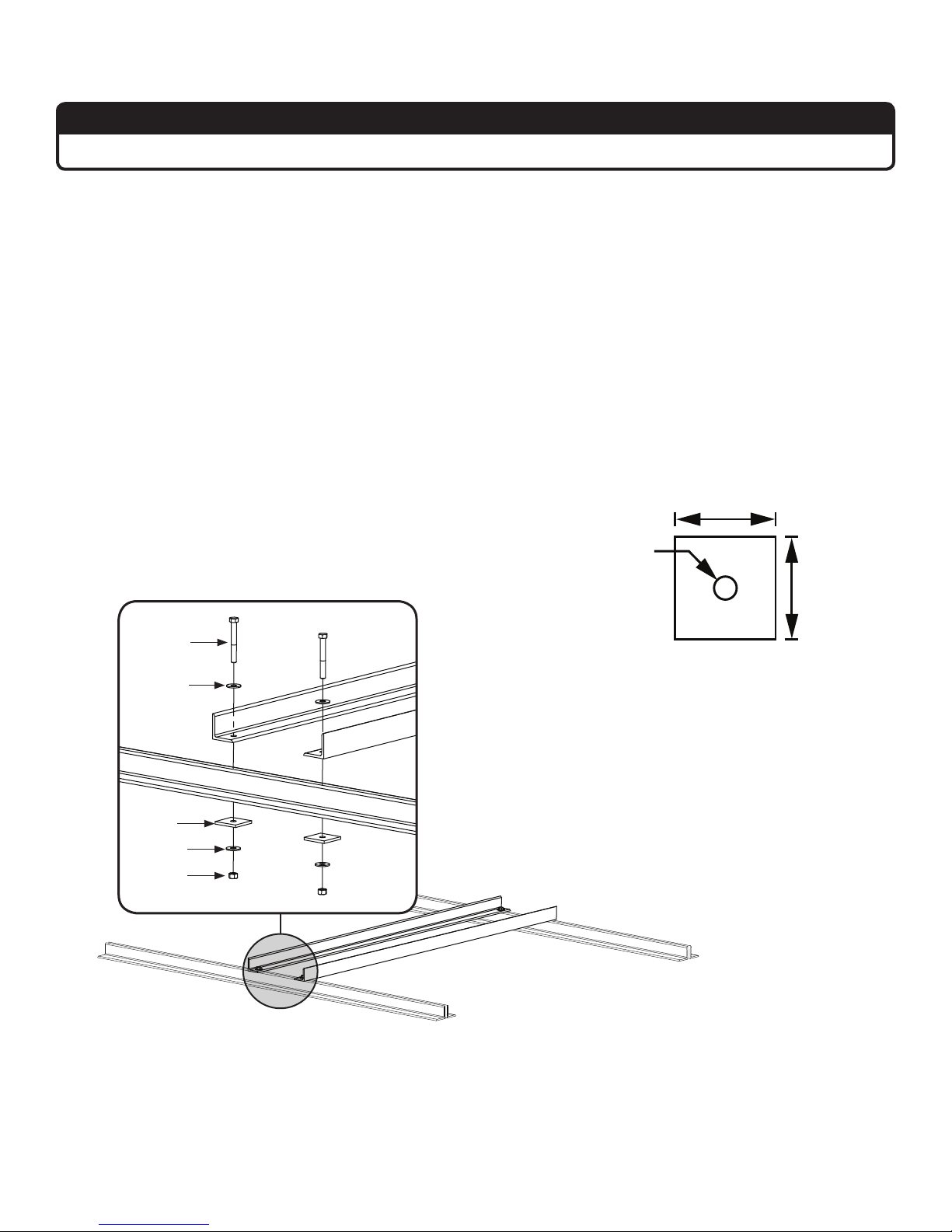
4a. Fasten single angle irons to roof structure mounting points
ATTENTION
If installation requires double angle irons (i.e., span is greater than 8 ft [2.4 m]), proceed to step 4b.
Fasten the angle irons to the roof structure mounting points at each end with customer-supplied Grade 8 hardware.
Do not tighten the hardware until the fan has been mounted to the angle irons.
Proceed to step 5.
Grade 8 Hardware (Customer-Supplied):
a. (4) 1/2-13 Bolt
b. (8) 1/2” Washer
c. (4) 3” Square Washer (BAF Supplied; see diagram)
d. (4) 1/2-13 Nylock Nut
Square Washer
3” (7.6 cm)
Ø 9/16”
(1.4 cm)
3”
(7.6 cm)
a
Thickness:
b
1/4” (6 mm)
c
b
d
10
WWW.BIGASSSOLUTIONS.COM © 2015 DELTA T CORP. ALL RIGHTS RESERVED.
Page 17
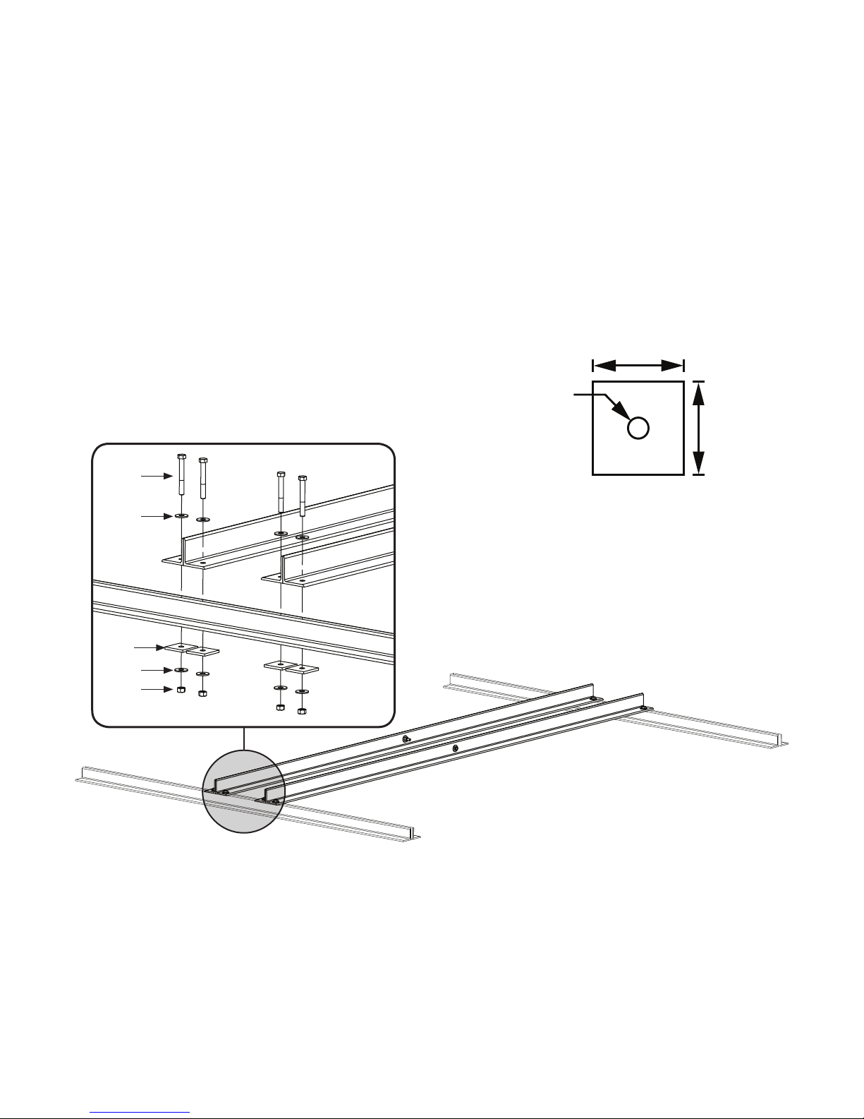
4b. Fasten double angle irons to roof structure mounting points
A
Fasten the angle irons to the roof structure mounting points at each end with customer-supplied Grade 8 hardware.
The angle irons with fan mounting holes should be positioned on the inside, facing each other. Do not tighten the
hardware until the fan has been mounted to the angle irons.
Grade 8 Hardware (Customer-Supplied):
a. (8) 1/2-13 Bolt
b. (16) 1/2” Washer
c. (8) 3” Square Washer (BAF-Supplied; see diagram)
d. (8) 1/2-13 Nylock Nut
Square Washer
3” (7.6 cm)
Ø 9/16”
(1.4 cm)
a
Thickness:
b
1/4” (6 mm)
3”
(7.6 cm)
c
b
d
WWW.BIGASSSOLUTIONS.COM © 2015 DELTA T CORP. ALL RIGHTS RESERVED.
11
Page 18
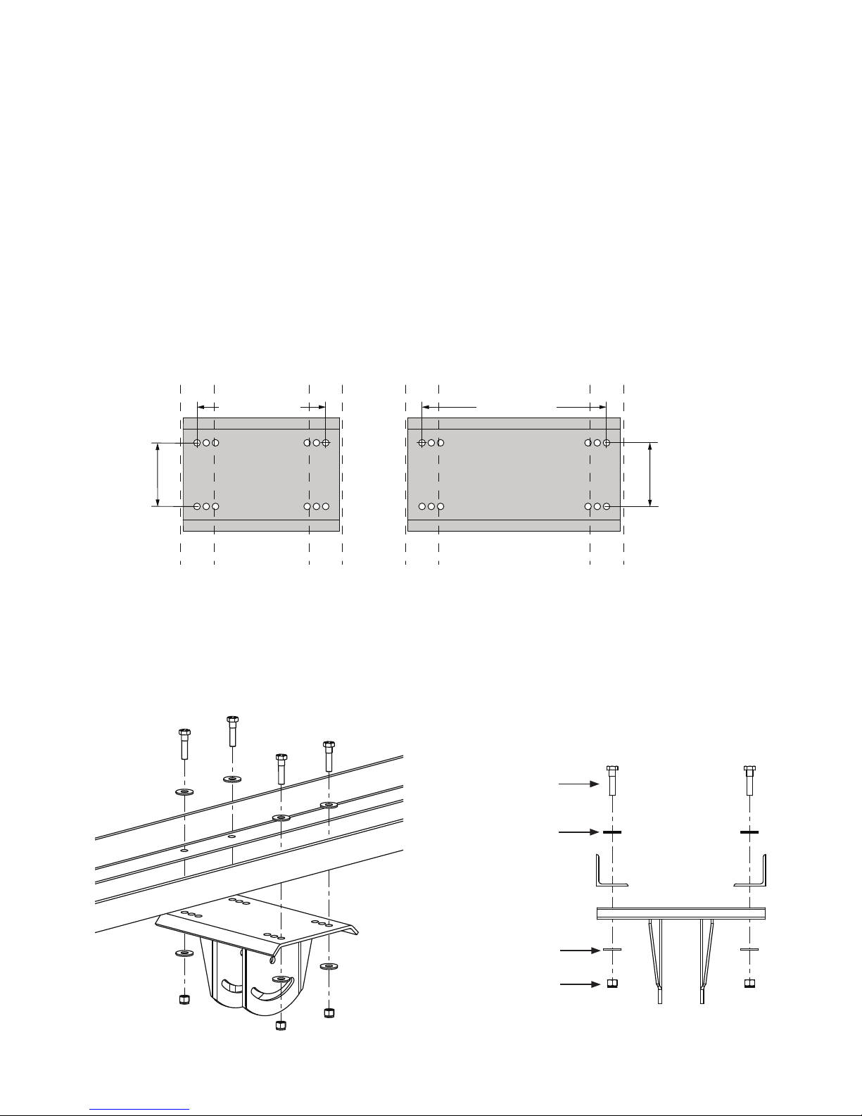
5. Attach upper yoke (to angle irons)
Secure the upper yoke directly to the angle irons with the Beam Clip Hardware as shown. The angle irons should
be aligned with the outermost holes of the upper yoke. Consult the diagrams below for distances between the
angle irons.
Tighten the bolts to 40 ft·lb (54.2 N·m) using a torque wrench and 3/4” socket. After attaching the upper yoke to
the angle irons, tighten all the bolts securing the angle irons to the roof structure to 40 ft·lb (54.2 N·m).
Proceed to “Hanging the Fan.”
Beam Clip Hardware:
a. (4) 1/2-13 x 2” GR 8 Bolt
b. (8) 1/2’’ Flat Washer
c. (4) 1/2-13 Nylock Nut
5.38”
(13.7 cm)
10-7/8”
(27.6 cm)
Small Upper Mount
13-3/4’’ (34.9 cm) x
9-5/8” (24.4 cm)
15-5/8”
(39.7 cm)
Large Upper Mount
18-1/2’’(46.9 cm) x
9-5/8”(24.4 cm)
Note: Dashed lines represent angle irons in the above illustrations.
5.38”
(13.7 cm)
Side View
a
12
WWW.BIGASSSOLUTIONS.COM © 2015 DELTA T CORP. ALL RIGHTS RESERVED.
b
b
c
Page 19
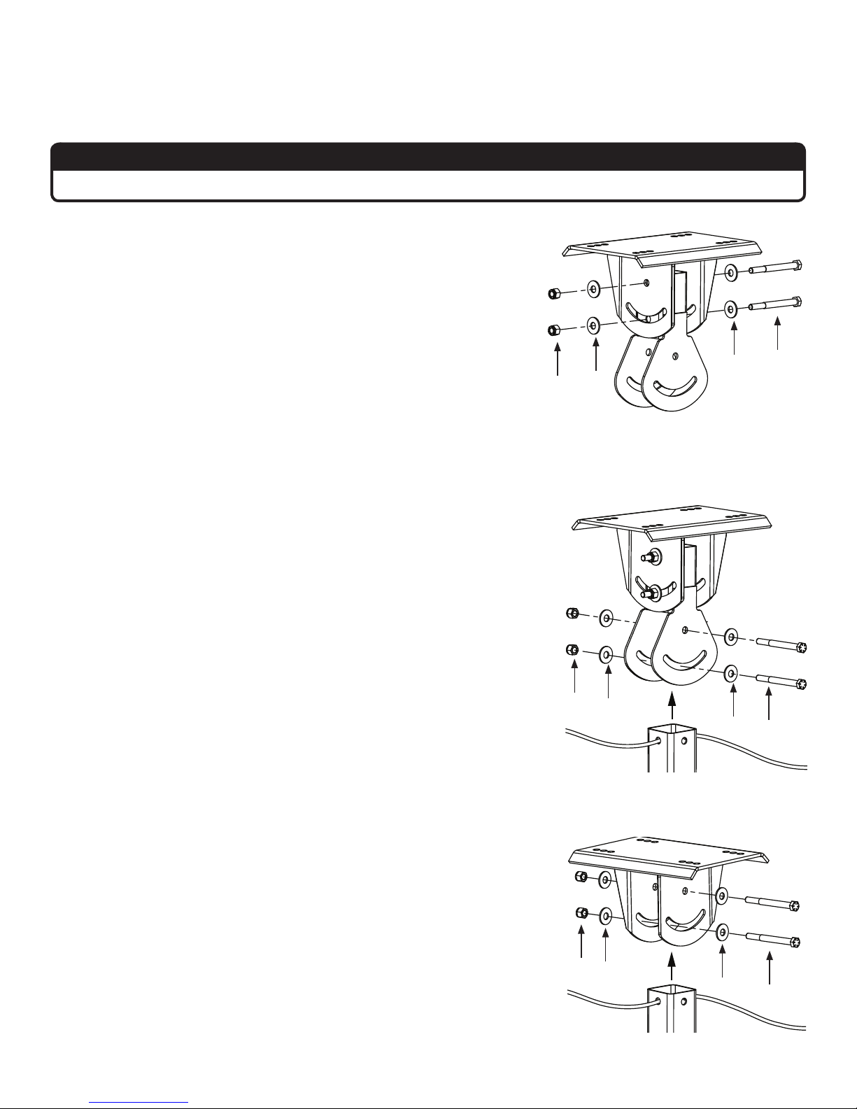
HANGING THE FAN
1. Attach balance joint (to upper yoke)
ATTENTION
If the fan will not be pivoted, it is not necessary to install the balance joint. Skip this step and proceed to Step 2b.
Fasten the balance joint to the upper yoke (already attached to mounting
structure) using the Balance/Pivot Hardware. Hand-tighten the bolts.
The fan’s balanced position can change depending on the pivot angle
of the fan or the angle of the roof. For this reason, do not fully tighten
these bolts until the fan is completely assembled.
Balance/Pivot Hardware:
a. (2) 1/2-13 x 5’’ GR 8 Bolt
b. (4) 1/2’’ Flat Washer
c. (2) 1/2-13 Nylock Nut
c
2a. Attach extension tube (to balance joint)
Fasten the extension tube to the balance joint with the Extension
Tube Hardware. Hand-tighten the bolts.
The fan’s balanced position can change depending on the pivot
angle of the fan or the angle of the roof. For this reason, do not fully
tighten these bolts until the fan is completely assembled.
Proceed to Step 3.
Extension Tube Hardware:
a. (2) 1/2-13 x 4-1/2’’ GR 8 Bolt
b. (4) 1/2’’ Flat Washer
c. (2) 1/2-13 Nylock Nut
c
b
b
b
b
a
a
2b. Attach extension tube (to upper yoke)
Fasten the extension tube to the upper yoke with the Extension Tube
Hardware.
Before tightening the bolts, allow the extension tube to hang freely and
balance itself. Tighten the bolts to 40 ft·lb (54.2 N·m) using a torque
wrench and 3/4” socket.
Extension Tube Hardware:
a. (2) 1/2-13 x 4-1/2’’ GR 8 Bolt
b. (4) 1/2’’ Flat Washer
c. (2) 1/2-13 Nylock Nut
WWW.BIGASSSOLUTIONS.COM © 2015 DELTA T CORP. ALL RIGHTS RESERVED.
c
b
b
a
13
Page 20
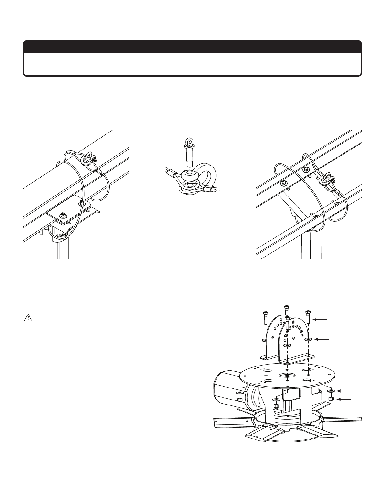
3. Secure upper safety cable
ATTENTION
The saftey cable is a crucial part of the fane and must be installed correctly. If you have questions, call
Customer Service for assistance.
Secure the safety cable to the I-beam or angle iron by wrapping the safety cable around it and securing the looped
ends with the shackle. The cable must be drawn tightly around the I-beam or angle iron, leaving as little slack as
possible. If possible, the shackle should be on the topside of the I-beam or angle iron. Securely tighten the shackle.
I-Beam Mount
Shackle
4. Attach main fan unit (to lower yoke)
Angle Iron Mount
CAUTION: When the fan is pivoted, the motor
should never be lower than the gearbox. This
will protect the motor in case the gearbox leaks.
Consider how the fan will eventually be pivoted
and position the lower yoke accordingly.
Attach the main fan unit to the lower yoke with the Main
Fan Unit Hardware.
Tighten the bolts to 40 ft·lb (54.2 N·m) using a torque
wrench and 3/4” socket.
Main Fan Unit Hardware:
a. (4) 1/2-13 x 1-3/4” GR 8 Bolt
b. (8) 1/2’’ Flat Washer
c. (4) 1/2-13 Nylock Nut
14
WWW.BIGASSSOLUTIONS.COM © 2015 DELTA T CORP. ALL RIGHTS RESERVED.
a
b
b
c
Page 21
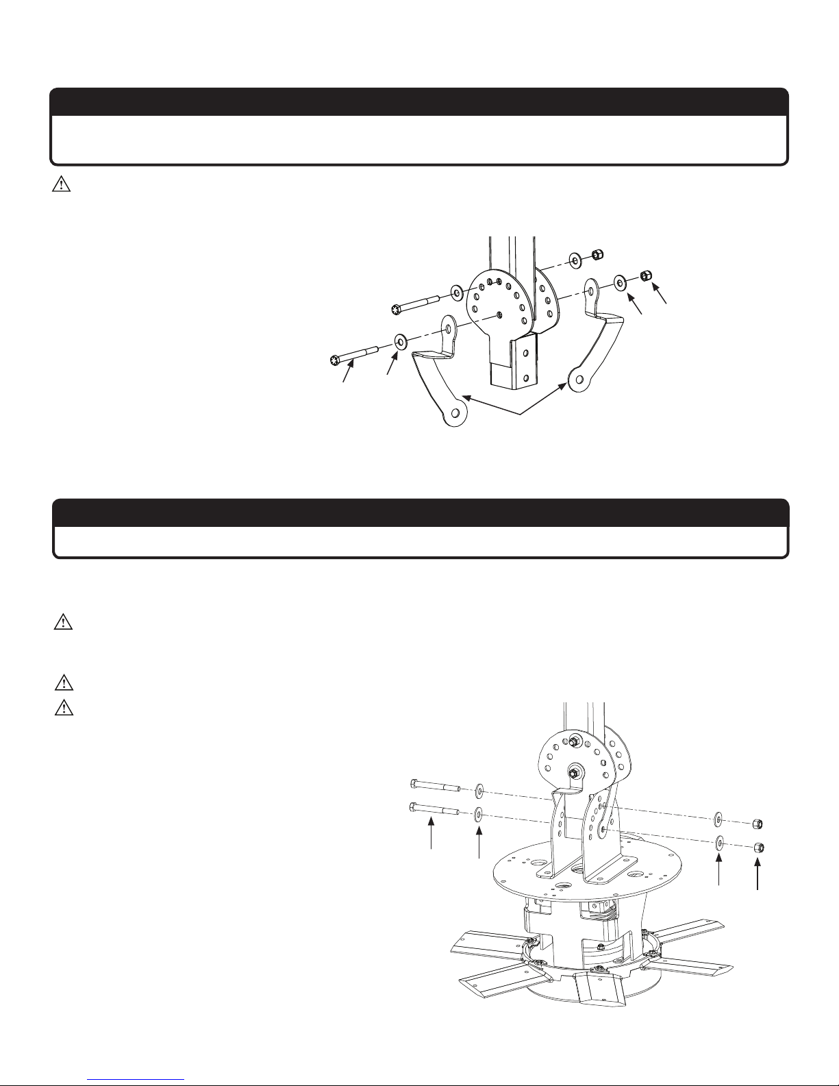
5. Attach pivot joint
ATTENTION
If the fan will not be pivoted, it is not necessary to install the pivot joint. Skip this step and proceed to Step
6b.
CAUTION: Install the bolts exactly as shown. Do not pivot the fan until it has been completely assembled.
Fasten the mount brackets and pivot joint to the extension tube with the Balance/Pivot Hardware as shown. Handtighten the bolts.
Balance/Pivot Hardware:
a. (2) 1/2-13 x 5’’ GR 8 Bolt
b. (4) 1/2’’ Flat Washer
c. (2) 1/2-13 Nylock Nut
c
b
a
b
Mount
Brackets
ATTENTION
Do not fully tighten bolts until fan is completely assembled!
6a. Attach lower yoke (to pivot joint)
CAUTION: When the fan is pivoted, the motor should never be lower than the gearbox. This will protect
the motor in case the gearbox leaks. Consider how the fan will eventually be pivoted and position the
motor accordingly.
CAUTION: Install the bolts exactly as shown. Do not pivot the fan until it has been completely assembled.
CAUTION: The motor frame is heavy. Use care when raising it.
Fasten the lower yoke and motor frame to the pivot
joint with the Lower Yoke Hardware. Hand-tighten
the bolts.
Proceed to Step 7.
Lower Yoke Hardware:
a. (2) 1/2-13 x 4-1/2’’ GR 8 Bolt
b. (4) 1/2’’ Flat Washer
c. (2) 1/2-13 Nylock Nut
WWW.BIGASSSOLUTIONS.COM © 2015 DELTA T CORP. ALL RIGHTS RESERVED.
a
b
b
c
15
Page 22
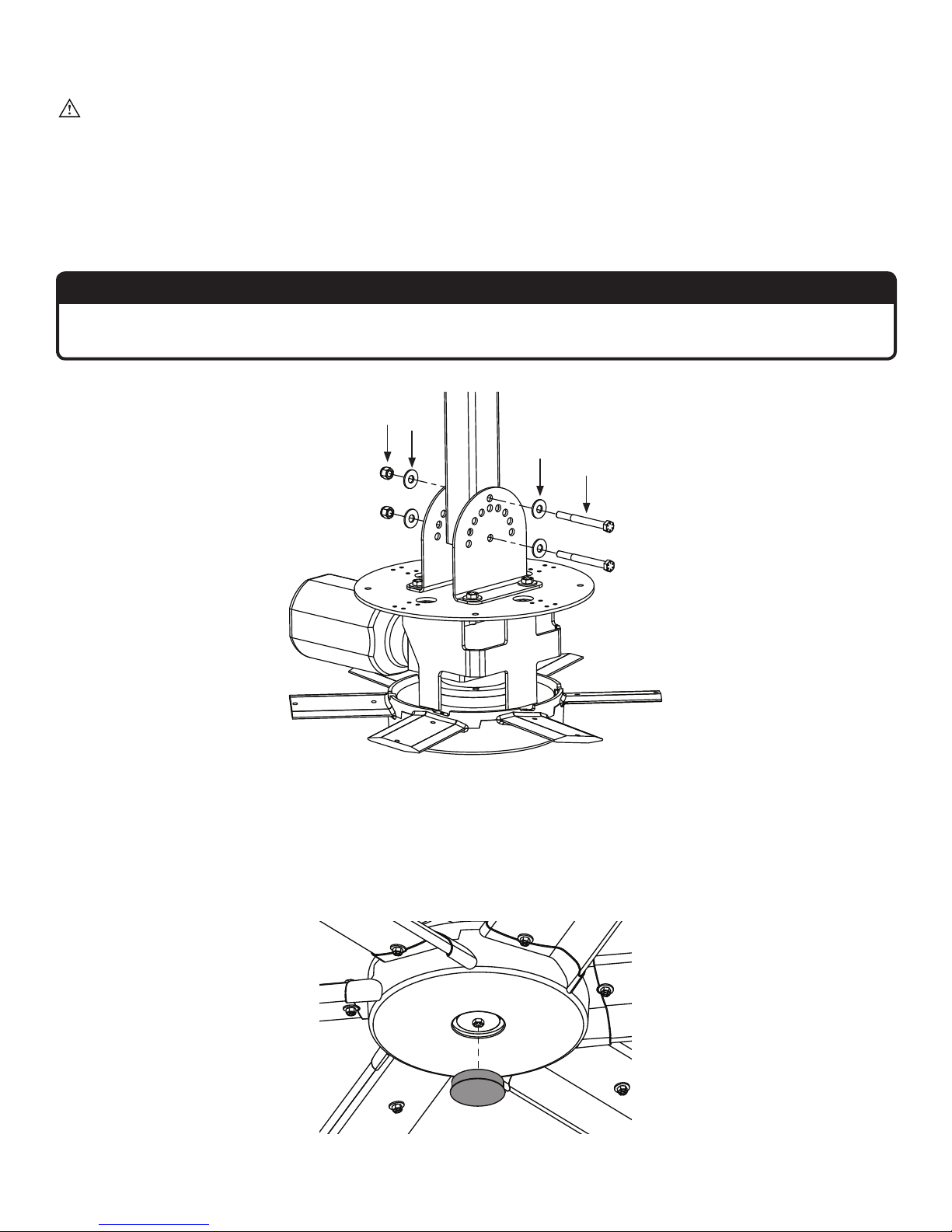
6b. Attach lower yoke (to extension tube)
CAUTION: The motor frame is heavy. Use care when raising it.
Fasten the lower yoke and motor frame to the bottom of the extension tube with the Lower Yoke Hardware.
Lower Yoke Hardware:
a. (2) 1/2-13 x 4-1/2’’ GR 8 Bolt
b. (4) 1/2’’ Flat Washer
c. (2) 1/2-13 Nylock Nut
ATTENTION
The lower yoke can only be attached to the extension tube through the uppermost and lowermost holes
on the lower yoke.
c
b
7. Attach center cap
Snap the center cap onto the bottom of the main fan unit.
Proceed to “Installing Airfoils” on the following page.
b
a
16
WWW.BIGASSSOLUTIONS.COM © 2015 DELTA T CORP. ALL RIGHTS RESERVED.
Page 23

INSTALLING THE AIRFOILS
1. Attach winglets
Attach the winglets to the ends of the airfoils with the Winglet
Hardware. Use a Phillips head and standard screwdriver to secure
the fastener.
Attach winglets to all six (6) airfoils before attaching airfoils to fan.
Winglet Hardware:
a. (6) 10-24 x 1/2’’ Bolt
b. (6) 10-24 x 3/4’’ Barrel
2. Position airfoils and trim
Slide the airfoil trim and airfoil onto the tab. An airfoil will only attach
to the fan hub in one direction. Forcing an airfoil into place could
damage it.
a
b
3. Attach airfoil retainers
Attach the six (6) airfoil retainers using the Airfoil Hardware.
Moving clockwise around the fan hub, position the airfoil retainers end over end. Hole A of the retainer should be
positioned over top of Hole B. Do not tighten the bolts until all the airfoil retainers have been attached!
Tighten all the bolts on the airfoil retainers to 29 ft·lb (39.3 N·m) using a torque wrench and 1/2” socket.
Airfoil Hardware:
a. (12) 5/16’’-18 x 2-1/4’’ GR 8 Bolt
b. (36) 5/16’’ Flat Washer
c. (12) 5/16’’-18 Nut
a
Airfoil Retainer
Hole B
Hole A
b
b
c
WWW.BIGASSSOLUTIONS.COM © 2015 DELTA T CORP. ALL RIGHTS RESERVED.
17
Page 24
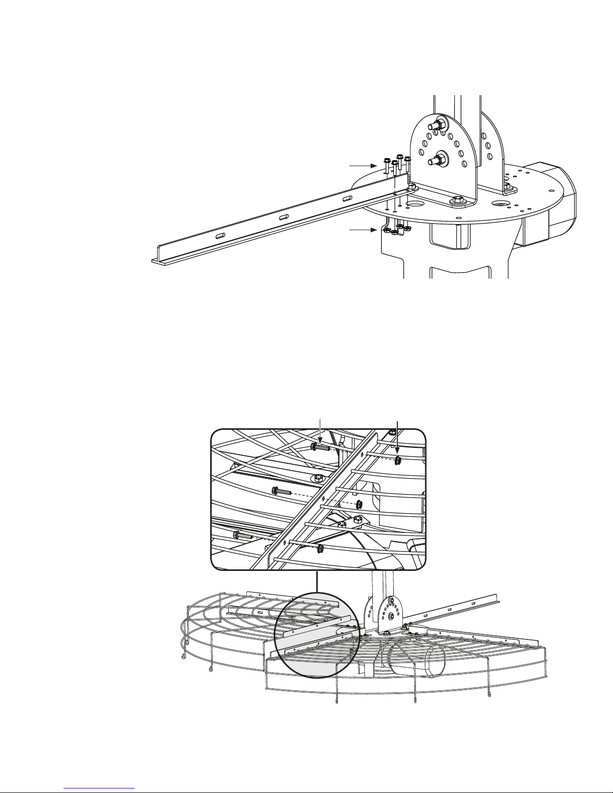
INSTALLING THE CAGE
1. Attach cage bracket
Attach the four (4) cage brackets with the Cage Hardware.
Cage Hardware:
a. (16) 1/4-20 x 1’’ Flange Bolt
b. (16) 1/4-20 Flange Nut
2. Attach upper cage
a
b
Attach the upper cage to the cage brackets using the Cage Hardware. Torque the bolts to 10 ft·lb (13.6 N·m).
Install one section at a time. Use the cage brackets to support sections during hardware installation. Make sure
the bolts secure adjacent sections.
Cage Hardware:
a. (12) 1/4-20 x 1’’ Flange Bolt
b. (12) 1/4-20 Flange Nut
a
b
18
WWW.BIGASSSOLUTIONS.COM © 2015 DELTA T CORP. ALL RIGHTS RESERVED.
Page 25
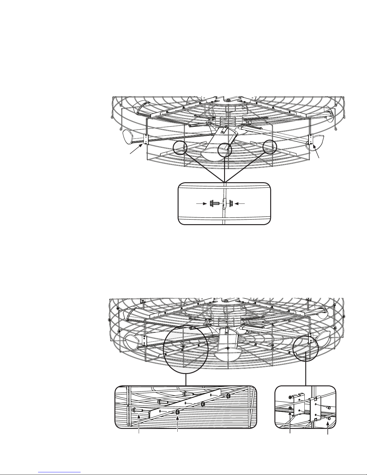
3. Attach lower cage sections (to upper cage)
Use two (2) outer cage clips (one on each end) to hang a lower cage section from the upper cage.
Secure the lower cage section to the upper cage using the Cage Hardware.
Repeat this step for the other cage sections. Make sure to secure adjacent sections first.
Cage Hardware:
a. (12) 1/4-20 x 1’’ Flange Bolt
b. (12) 1/4-20 Flange Nut
outer
cage clip
outer
cage clip
a b
4. Secure lower cage
Fasten the lower cage sections to each other using the Cage Hardware (1/4-20 bolts and nuts) as shown. Torque
the bolts to 10 ft·lb (13.6 N·m).
Attach the inner cage clips to the outer cage clips using the Cage Clip Hardware (10-32 bolts and nuts).
Cage and Cage Clip Hardware:
a. (12) 1/4-20 x 1’’ Flange Bolt
b. (12) 1/4-20 Flange Nut
c. (8) 10-32 x 1/2” Flange Bolt
d. (8) 10-32 Flange Nut
WWW.BIGASSSOLUTIONS.COM © 2015 DELTA T CORP. ALL RIGHTS RESERVED.
a
b
c
d
19
Page 26
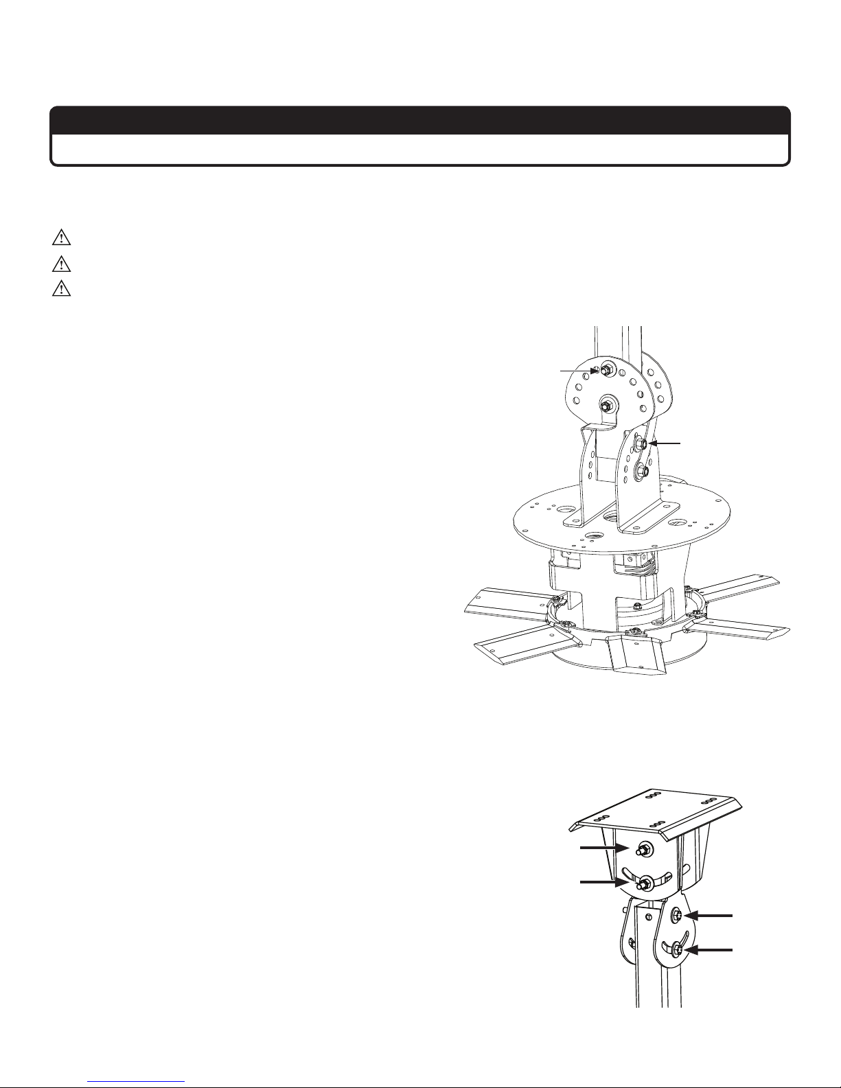
PIVOTING THE FAN
ATTENTION
If you are not pivoting the fan, proceed to “Installing Guy Wires” on the following page.
1. Adjust pivot joint and lower yoke
WARNING: Do not remove the bottom bolt of the pivot joint or the bottom bolt of the lower yoke.
CAUTION: When the fan is pivoted, the motor should not be lower than the gearbox.
WARNING: Before tightening the bolts, make sure the fan blades are clear of any obstructions including
the safety cable and motor power cable.
Using caution, change the hole of the top bolt (A) on the
pivot joint and/or the top bolt (B) on the lower yoke to pivot
the direction of the fan. Remove only one bolt at a time.
When satisfied with the angle of pivot, tighten all the bolts
on the pivot joint and the lower yoke. Tighten the bolts to
40 ft·lb (54.2 N·m) using a torque wrench and 3/4” socket.
a
b
2. Tighten bolts on upper yoke and balance joint
Tighten the four (4) bolts on the upper yoke and the balance joint.
Before tightening the bolts, let the fan hang freely so it can adjust its
center of gravity.
Tighten the bolts to 40 ft·lb (54.2 N·m) using a torque wrench and
3/4” socket.
Proceed to “Installing Guy Wires” on the following page.
20
WWW.BIGASSSOLUTIONS.COM © 2015 DELTA T CORP. ALL RIGHTS RESERVED.
Page 27
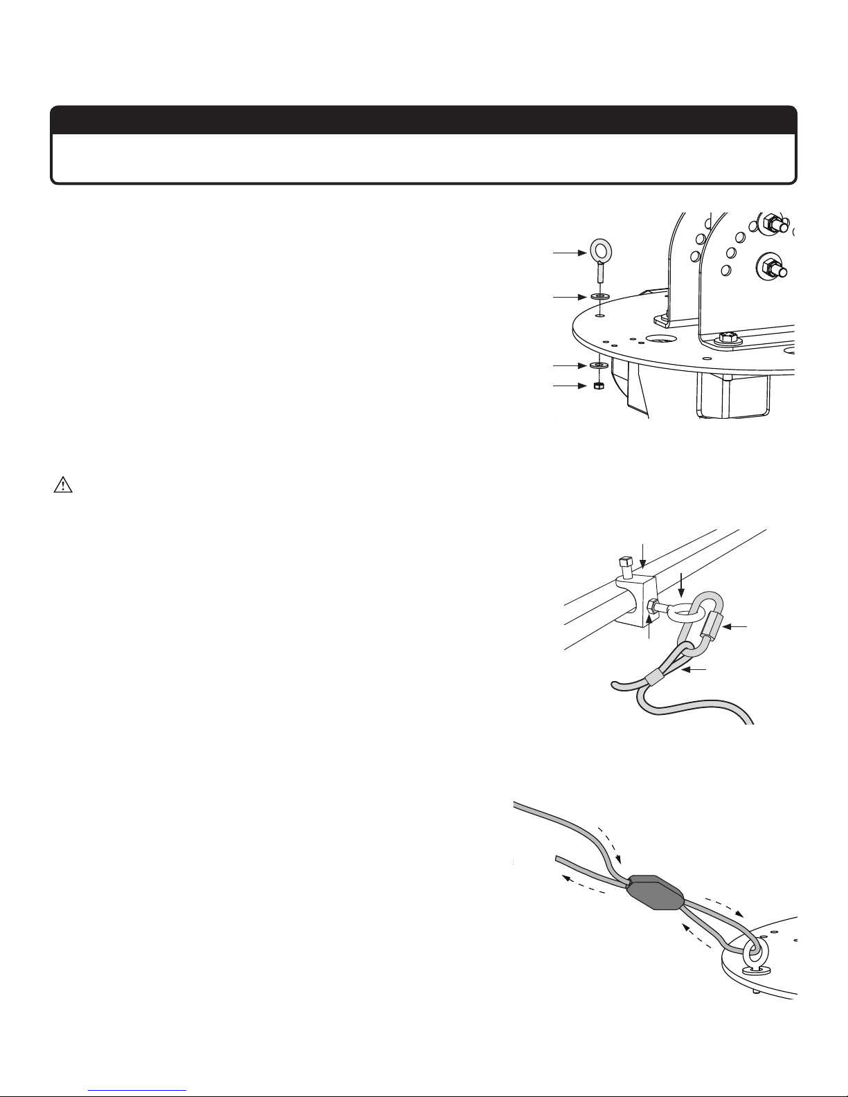
INSTALLING THE GUY WIRES
ATTENTION
Guy wire installation is recommended if the fan’s extension tube is 4 ft (1.2 m) or longer, if the fan is pivoted,
if the fan is exposed to hgh winds, or if the fan is close to any building fixtures.
1. Attach eyebolt to motor frame
Attach the large eyebolt to the motor frame with the Guy Wire
Hardware.
Guy Wire Hardware:
a. (1) 3/8-16 x 1” Eyebolt
b. (2) 3/8” Washer
c. (1) 3/8-16 Nylock Nut
2. Attach beam clamp
CAUTION: When taut, the guy wire must be clear of moving
fan airfoils. Place the beam clamp accordingly.
Attach the beam clamp to an I-beam, bar joist, or other approved
mounting structure.
Fasten the small eyebolt and nut onto the beam clamp. The nut will
be on the outside of the beam clamp.
Loop the crimped end of the guy wire into the locking carabiner and
secure to the eyebolt. Securely tighten the carabiner.
Guy Wire Hardware:
a. 1/4” Beam Clamp
b. 1/4-20 x 1” Eyebolt
c. 1/4-20 Hex Nut
d. Locking Carabiner
e. Guy Wire
a
b
b
c
Beam Clamp
a
b
d
c
e
3. Route guy wire through Gripple
Route the guy wire through the Gripple, the eyebolt on the motor
frame, and then back through the Gripple as shown. Do not tighten
the Gripple until the remaining guy wires have been installed.
Note: To back the guy wire out of the Gripple, insert 1/16 (1.5 mm)
Allen wrench into the small hole on the Gripple.
WWW.BIGASSSOLUTIONS.COM © 2015 DELTA T CORP. ALL RIGHTS RESERVED.
®
Gripple
21
Page 28
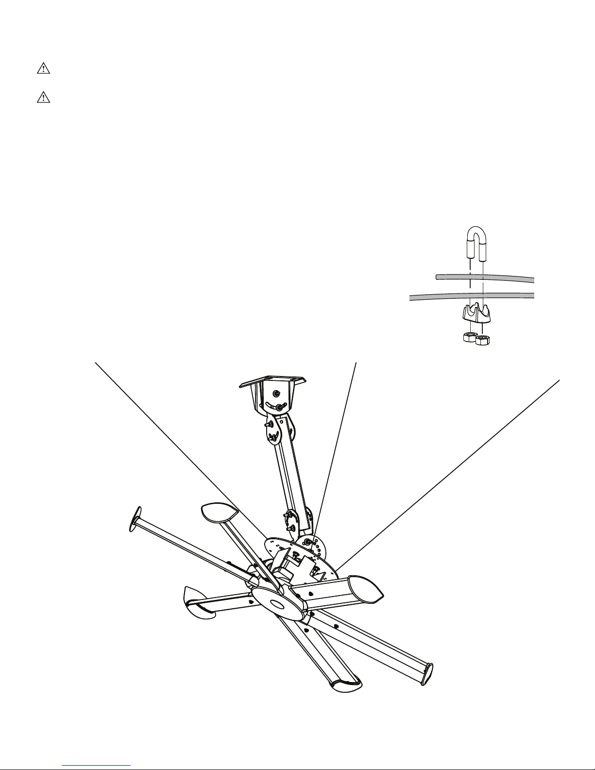
4. Install remaining guy wires
CAUTION: Over-tightening the guy wires could throw the fan o balance.
CAUTION: The guy wires should be spaced evenly around the fan and clear of the airfoils.
Repeat steps 1–3 to install the three (3) remaining guy wires.
®
Evenly cinch all four guy wires into place using the Gripples
airfoils or into the cage. The guy wires should be taut.
Once all of the guy wires are taut, secure their loose ends with the wire rope clips.
. Route the guy wires so they do not cross into the
Wire Rope Clip
22
WWW.BIGASSSOLUTIONS.COM © 2015 DELTA T CORP. ALL RIGHTS RESERVED.
Page 29

ELECTRICAL INSTALLATION
WARNING: To reduce the risk of electric shock, wiring should be performed by a qualified electrician! Incorrect
assembly can cause electric shock or damage the motor and the controller! Hazard of electrical shock!
WARNING: The installation of a Big Ass Fan must be in accordance with the requirements specified in this installation
manual and with any additional requirements set forth by the National Electric Code (NEC), ANSI/NFPA 70-2011, and all
local codes. Code compliance is ultimately YOUR responsibility!
WARNING: The fan controllers contain high voltage capacitors that take time to discharge after removal of mains
supply. Before working on the fan controller, ensure isolation of mains supply from line inputs at the fan controller’s
disconnect if installed (L1, L2/N, and L3). Wait three (3) minutes for capacitors to discharge to safe voltage levels.
Failure to do so may result in personal injury or death. Note: Darkened display LEDs are not an indication of safe
voltage levels.
CAUTION: It is the sole responsibility of the installer to verify the operating voltage of the fan system prior to
installation! It is also mandatory that the installer verify that airfoils, motor hub assemblies, and fan controllers are
matched properly at the time of installation, especially if multiple fan systems will be installed.
CAUTION: An incorrectly installed controller can result in component damage or reduction in the fan’s life. Wiring
or application errors such as under-sizing the controller, incorrect or inadequate AC supply, or excessive ambient
temperatures may result in a malfunction of the fan system. Verify correct voltage, phase, and horsepower before
beginning installation!
WARNING: Exercise caution and common sense when powering the fan. Do not connect the fan to a damaged or
hazardous power source. Do not attempt to resolve electrical malfunctions or failures on your own. Contact Big Ass
Fans if you have any questions regarding the electrical installation of this fan.
CAUTION: For use with Big Ass Fans-supplied variable frequency drive only. Not for use with other speed control
devices!
CAUTION: Shielded cable, if applicable, must be landed on the motor’s ground terminal!
CAUTION: To avoid a short circuit, be very careful not to get metal chips in the controller!
CAUTION: The Big Ass Fans product warranty will not cover equipment damage or failure that is caused by improper
installation.
CAUTION: The following information is merely a guide for proper installation. The Big Ass Fans Company cannot
assume responsibility for the compliance or the non-compliance to any code, national, local, or otherwise for the proper
installation of these fan controllers, fans, or associated equipment. A hazard of personal injury and/or equipment
damage exists if codes are ignored during installation
Electrical installation overview
The electrical installation section is intended for a professional electrician. If you are unfamiliar or uncomfortable
with installing electrical components, do not attempt to install the fan without an electrician. Serious personal
injury or damage to the fan and other equipment could result. This guide is merely a recommendation of proper
installation. Adhering to national and local electric codes is your responsibility. It is the sole responsibility of the
installer to verify the operating voltage of the fan system prior to installation! It is also mandatory that the installer
verify that airfoils, motor assemblies, and fan controllers are matched properly at the time of installation, especially
if multiple fan systems will be installed.
The following sections outline how to prepare for the electrical installation, and include the required cables and
how to properly route the cabling through conduit, how to properly ground the fan system, how to properly wire
the fan controller, how to properly wire the fan motor, and proper startup procedures.
Controller storage
Store the controller within an ambient temperature range of -40° F to 185° F (-40° C to 85° C) and a relative humidity
range of 0 to 95%, non-condensing. Do not expose the controller to a corrosive atmosphere. If the controller has
been in storage or disconnected from power for more than one year, apply AC supply power to the controller for
a period of two hours prior to operation in order to recondition the internal DC bus capacitors.
WWW.BIGASSSOLUTIONS.COM © 2015 DELTA T CORP. ALL RIGHTS RESERVED.
23
Page 30
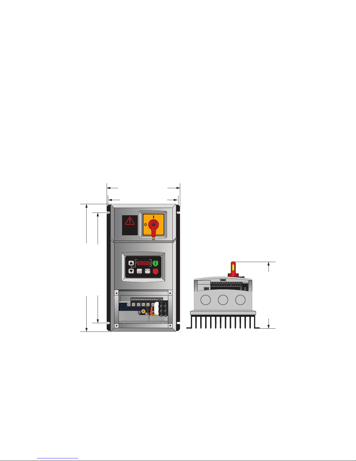
Power requirements for fan controllers
The power requirements for Big Ass Fans controllers are shown in the specification table in the introduction.
If multiple controls are connected to one feeder circuit, the circuit required is the sum of the feeder circuit
requirements listed on the chart. For example, if two 240 V, 3 Φ controllers are connected to a single feeder
circuit, that circuit needs to be rated for 20 amps. This type of installation will also require that each fan control be
installed downstream from a dedicated over-current protection device
Mounting the wall controller
Mount the controller to a wall using a #8–#10 screw. Adhere to the following guidelines when selecting the
controller location:
• Install the controller on a flat surface that is readily accessible, free from vibration, and where there is adequate
distance from foreign objects or moving equipment.
• Do not mount any controller adjacent to or above a heat source or heat-producing equipment.
• The ambient temperature must be between 14º F (-10º C) and 122º F (50º C).
• Do not expose the controller to a corrosive atmosphere or direct sunlight.
• When mounting the controller, keep in mind that the fan should be visible from the controller.
• A minimum distance of 6” (15.2 cm) should be maintained between fan controllers.
Note: Multiple fan controllers are available as a special order only. Please contact Customer Service for more information.
6.25” (159 mm)
5.95” (151 mm)
WARNING
DONOT USE THIS
DISCONNECTTO
STARTAND STOP THE
FAN.PERMANENT
9.5” (241 mm)
10.9” (277 mm)
DAMAGEWILL
RESULT!
1 2 5 6 13A13B13C 14 30 16 1725 4 11
1 2 5 6 13A13B13C 14 30 16 1725 4 11
U/T1 V/ T2 W/T3
SCA ME
SCA ME
AUTO FWD
M
PE
REV
R F
L1 L2 L3
Input power conditioning
RUN
STOP
L1
L2
L3
5.51” (140 mm)
Line reactors should be installed if AC supply is subject to any of the following:
• Low line impedance
• Frequent power interruptions
• Phase-to-ground voltage in excess of 125% nominal phase-to-phase voltage
• Distribution system exceeds established kVA limit for your specific model (contact Big Ass Fans for more
information).
• Power factor correction capacitors
• Intermittent noise spikes (lightning)
24
WWW.BIGASSSOLUTIONS.COM © 2015 DELTA T CORP. ALL RIGHTS RESERVED.
Page 31
Conduit and piping guidelines
CAUTION: The presence of foreign signals on a drive’s output wiring greatly reduces the controller’s ability to
control current and speed regulation of the fan. Any wiring practice that would allow this kind of “cross-talk”
must be avoided. Failure to do so may result in nuisance tripping and/or premature equipment failure. Sources
of foreign signals that could induce such signals include another VFD’s output circuit, long “across-the-line”
motor circuits, and lighting circuits.
CAUTION: Recommendations for fan controller output/motor lead routing deem some conventional wiring
practices “unacceptable.” National and/or local code does not dierentiate between solid-state and
electromechanical systems; however, due to the nature of the Big Ass Fan system, there are additional
requirements that must be met to ensure proper operation.
The nature of Variable Frequency Drive systems (VFD) must be considered prior to and during the installation of
Big Ass Fans. Due to high frequency electrical noise on the output side of the fan controller, measures must be
taken to ensure that wires and cabling are routed in a manner consistent with recommendations made in this
section. Big Ass Fans controllers rely on “motor feedback” through the cabling to sense motor speed, slip, etc.
Controller AC supply
Most conventional methods of power distribution and branch circuit installation apply to all models of fan controllers.
Installation must comply with specifications regarding wire types, conductor sizes, branch circuit protection, and
disconnecting devices. Failure to do so may result in personal injury and/or equipment damage.
• AC supply feeds for one fan controller can share the same conduit with AC supply feeds for one or more additional
controllers.
• AC supply feeds for a fan controller and output/motor leads for the same fan controller cannot share a conduit.
• AC supply feeds for one fan controller cannot share conduit with output/motor leads from one or more additional
controllers/VFDs.
• Any unused conductors that share a conduit with an AC supply feed should be grounded on both ends to prevent
risk of electric shock due to induced voltages.
• Output/motor leads for a fan controller and AC supply feeds for the same fan controller cannot share a conduit.
• Output/motor leads for one fan controller cannot share conduit with AC supply feeds or output/motor leads from one
or more additional fan controllers.
• Any unused conductors that share a conduit with fan controller output/motor leads should be grounded on both ends
to prevent risk of electric shock due to induced voltages.
Power wiring guidelines
In order to satisfy some code requirements, it may be necessary to install a manual disconnect at the fan
motor location when the fan assembly is not within “line-of-sight” from the fan controller. A non-fused, 600
V, 3-phase, blade-style disconnect should be used to satisfy this “line-of-sight” requirement.
WARNING: Installation must comply with specifications from National Electrical Codes and standards
(NEC, VDE, BSI, etc.) regarding wire types, conductor sizes, branch circuit protection, and disconnecting
devices.
WARNING: To avoid a possible shock hazard and/or nuisance tripping caused by induced voltages, unused
wires in the conduit must be grounded at both ends. For the same reason, fan controller output wires
should not share a conduit with another fan controllers output leads, or other power circuits.
CAUTION: MC or “Metal clad” cable cannot be used for controller output/motor leads. Both stranded and
solid core varieties must be avoided. Do not use solid core cable of any size or insulation class for motor
wiring. Use of such types of cabling may result in nuisance tripping or premature equipment failure.
WWW.BIGASSSOLUTIONS.COM © 2015 DELTA T CORP. ALL RIGHTS RESERVED.
ATTENTION
25
Page 32

A variety of cable types are acceptable for variable frequency drive installations. For many installations, unshielded
cable is adequate if it can be separated from sensitive circuits. In all cases, parallel runs of control and motor
cabling should be avoided when unshielded cable is used. Do not use cable with an insulation thickness of less
than 15 mils.
• UL installations in 50º C ambient must use 600 V, 75º C or 90º C wire.
• UL installations in 40º C ambient should use 600 V, 75º C or 90º C wire.
Acceptable unshielded types
THHN, THNW, or similar wire is acceptable for drive installations in dry environments if adequate free air space
and/or conduit fill rate limits are provided. Do not use THHN or similarly coated wire in wet areas. Any wire chosen
must have a minimum insulation thickness of 15 mils and should not have large variations in insulation concentricity.
Acceptable shielded types
The drain conductor included with shielded cables must be connected to both the motor frame and the PE/Ground
terminal of the Variable Frequency Drive.
Location Rating / Type Description
Standard
(Option 1)
Standard
(Option 2)
Class I & II
Division I & II
600 V, 75º C or 90º C (167º F or
194º F) RHH/RHW-2
Belden 29501-29507 or equivalent
Tray rated 600 V, 75º C or 90º C (167º F
or 194º F) RHH/RHW-2
Shawflex 2 ACD/3 ACD or equivalent
Tray rated 600 V, 75º C or 90º C (167º F
or 194º F) RHH/RHW-2
• Four tinned conductors with XLPE insulation
• Foil shield and tinned copper drain wire with 85% braid
coverage
• PVC Jacket
• Three tinned copper conductors with XLPE insulation
• 5 mil single helical copper tape (25% overlap minimum) with
three bare copper grounds in contact with shield
• PVC Jacket
• Three bare copper conductors with XLPE insulation with
impervious corrugated continuously welded aluminum armor
• Black sunlight resistant PVC jacket overall
• Three copper grounds on #10 AWG and smaller
Maximum cable lengths
To prevent nuisance trips, the distance between the controller and the fan should not exceed 400 ft (122 m).
Output disconnects
A device, such as a contactor, that routinely disconnects and reapplies output power to the motor for the purpose
of starting and stopping the motor cannot be used.
Recommended wire size
A minimum of 14 AWG is acceptable for motor leads. 14 AWG applies to motor leads only. Power feeders to
controllers must be governed by the fuse size included with the fan controller and/or required circuit breaker.
Grounding
The nature of Variable Frequency Drive systems must be considered prior to and during the installation of Big Ass
Fans. Due to high frequency content on the output side of the fan controller, measures must be taken to ensure
that all grounding connections conform to the recommendations made in this section.
The fan controller’s safety ground
conform to the requirements of national and local industrial safety regulations and/or electrical codes. The integrity
of all ground connections should be periodically checked. All ground leads for downstream conduit boxes must be
kept separate from the motor ground and terminated on the fan controller’s PE terminal.
Motor ground
(PE) must be connected to system ground. Ground impedance must
The motor ground must be connected to a ground terminal on the VFD to aid in keeping high frequency electrical
noise o of the building’s ground grid.
26
WWW.BIGASSSOLUTIONS.COM © 2015 DELTA T CORP. ALL RIGHTS RESERVED.
Page 33
Motor ground
The motor ground must be connected to a ground terminal on the VFD to aid in keeping high frequency electrical
noise o of the building’s ground grid.
Shielded motor cable terminations
Either of the safety ground terminals on the drive provides a grounding point for the motor cable shield. The motor
cable shield connected to one of the drive terminals must also be connected to the motor frame. If no drain lead
is present, the cable must be stripped back so that the braid can be twisted and soldered to a pigtail for proper
termination.
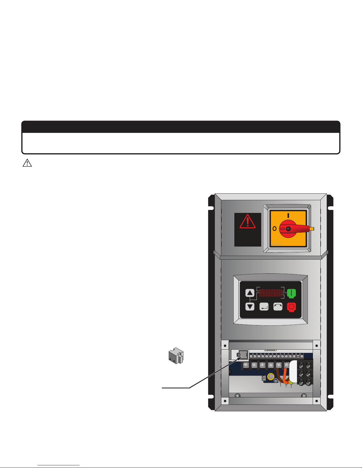
Installing the Electronic Programming Module (EPM)
ATTENTION
If hanging multiple fans, ensure to install the exact EPM included in each fan’s packaging. EPMs are not
interchangeable!
CAUTION: Install the EPM prior to applying power to the fan controller!
The Electronic Programming Module (EPM) contains all
programming information specific to fan operation. It must
be installed prior to applying power to the fan controller.
This module is provided as part of the fan’s accessory kit.
To install the EPM, disconnect the fan from power (refer
to the position of the disconnect switch below). Insert the
EPM in the location shown below. Note: The EPM can
only be inserted one way. Do not force it!
Electronic
Programming
Module
WAR NING
DO NOT US E THIS
DISCONNEC T TO
STAR T AND S TOP THE
FAN. PE RMANE NT
DAMAGE WILL
RES ULT!
1 2 5 6 13A 13B 13C 14 3 0 1 6 1 725 4 11
1 2 5 6 13A 13B 1 3C 14 30 1 6 1 725 4 11
U/T1 V/T2 W/T3
SCAME
SCAME
AUTO FWD
M
R F
PE
RUN
REV
STOP
L1
L2
L1 L2 L3
L3
BRN
ORG
YEL
WWW.BIGASSSOLUTIONS.COM © 2015 DELTA T CORP. ALL RIGHTS RESERVED.
27
Page 34
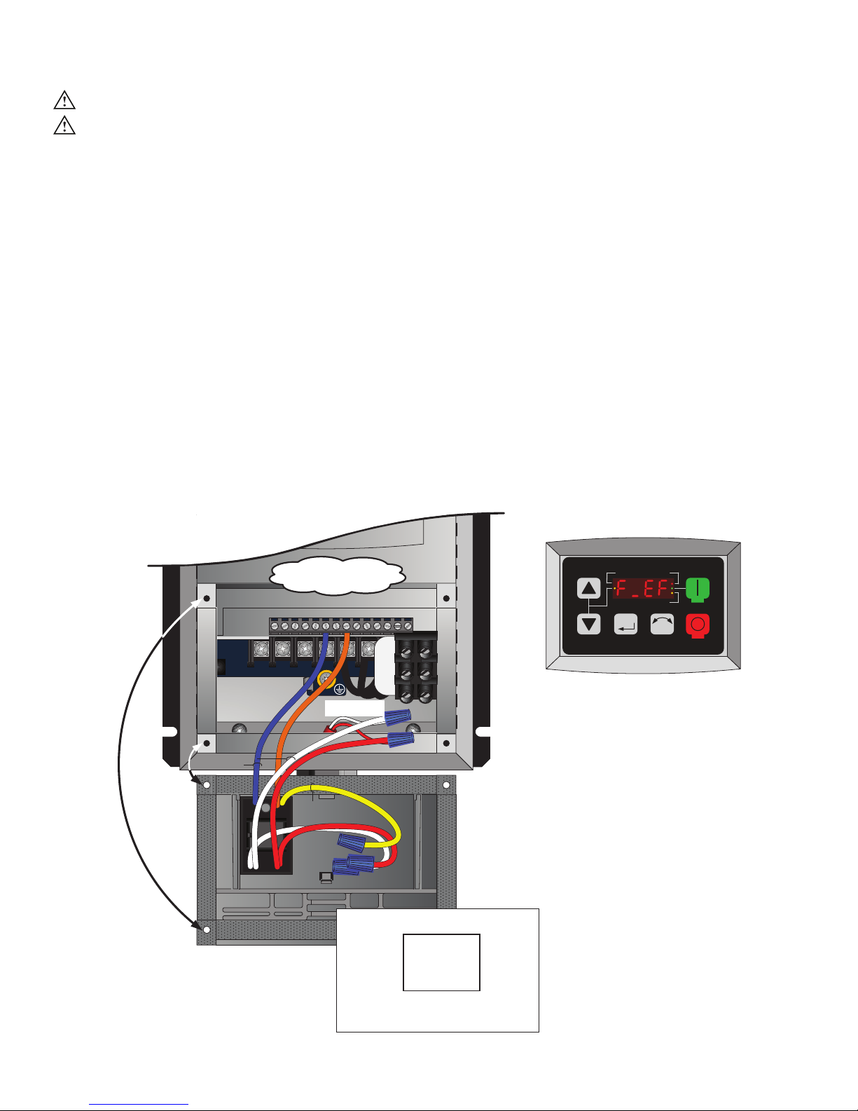
Wiring: Early Suppression Fast Response (ESFR)
WARNING: Wait three minutes after disconnecting before servicing!
WARNING: Improper installation can cause electric shock or damage to the motor and controller. A
qualified electrician should perform the installation.
ATTENTION: If installing the fan in the United States, the fan must be installed per the following National Fire
Protection Association (NFPA) guidelines:
• The fan must be centered approximately between four adjacent sprinklers.
• The vertical distance from the fan to the sprinkler deflector must be at least 3 ft (91.4 cm).
• The fan must be interlocked to shut down immediately upon receiving a waterflow signal from the alarm
system.
The fire relay included with the fan is needed only if the fan will be installed in a building that has a fire sprinkler
system. The fire relay integrates the fan with the sprinkler system and shuts down the fan upon receiving an alarm
signal from the system. If the building in which the fan will be installed has a sprinkler system, you must install the
relay according to the instructions below.
A contact closure across the digital input terminals 4 and 13A will result in fan shutdown. The included relay uses
a Normally Open (N.O.) contact as shown below. The relay coil must be energized by the FACP for fan shutdown.
Optionally, the normally closed (N.C.) relay contact can be used. The relay coil must remain energized by the FACP
for fan operation. This would be considered a fail safe or fail open wiring arrangement. Two additional relay coil
leads are provided to facilitate supervision pass-through where required.
Terminals 4 & 13A for
1 2 5 6 13A 1 3B 13C 1 4 3 0 16 1725 4 1 1
1 2 5 6 13A 1 3B 13C 1 4 3 0 1 6 1725 4 1 1
U/T1 V/T2 W/T3
ORG
BLU
PAM-SD
WHT
RED
Relay is mounted to the
backside of the access cover.
ESFR Relay
L1
PE
YEL
From Main FACP or
NAC Box if
L2
L1 L2 L3
Applicable
L3
Relay Coil/Contact Details
White (X2) (-) C Blue
Red (X2) (+) NO Orange
Coil: 20–32 VDC @ 20 mA
NC Yellow
AUTO FWD
RUN
REV
M
R F
STOP
An alarm condition will stop twhe
fan and issue an “F_EF” external
fault on the controller’s display.
28
WWW.BIGASSSOLUTIONS.COM © 2015 DELTA T CORP. ALL RIGHTS RESERVED.
Page 35
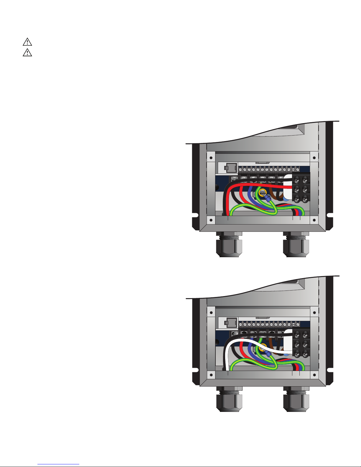
Wiring: 100–125/200–250 V, single-phase fan controllers
WARNING: Wait three minutes after disconnecting before servicing!
WARNING: Improper installation can cause electric shock or damage to the motor and controller. A
qualified electrician should perform the installation.
The diagrams below shows wiring option for a 100–125/200–250 V, 1 Φ fan controller. See “Power Requirements
for Fan Controllers” for detailed power requirements.
Wiring for 200–250 V, 1 Φ, 50/60 Hz
fan controllers
The neutral terminal is not used when wiring the fan
controller for 200–250 V, 1 Φ. A disconnect and EMI
filter are included with this fan controller.
Note: This fan controller does not contain fusing!
Power must be supplied to this controller via
a dedicated circuit breaker or properly fused
disconnect!
1 2 5 6 13A13B13C 14 30 16 1725 4 11
1 2 5 6 13A13B13C 14 30 16 1725 4 11
U/T1 V/T2 W/T3
PE
L1 L2 L3
L1
L2
N
Optional wiring for 100–125 V, 1 Φ, 50/60 Hz
fan controllers
The L2 terminal is not used when wiring the fan
controller for 100–125 V, 1 Φ. A disconnect is included
with this fan controller.
Note: This fan controller does not contain fusing!
Power must be supplied to this controller via
a dedicated circuit breaker or properly fused
disconnect!
BLK
GRN/YEL
RED
AC Input Wiring
2W plus GND
1 2 5 6 13A13B13C 14 30 16 1725 4 11
1 2 5 6 13A13B13C 14 30 16 1725 4 11
U/T1 V/T2 W/T3
BLK
GRN/YEL
WHT
RED
GRN/
YEL
BLK
BLU
Motor Output Wiring
3W plus GND
L1
PE
L1 L2 L3
L2
N
RED
GRN/
YEL
BLK
BLU
WWW.BIGASSSOLUTIONS.COM © 2015 DELTA T CORP. ALL RIGHTS RESERVED.
AC Input Wiring
2W plus GND
Motor Output Wiring
3W plus GND
29
Page 36
U
/T1V/T2W/T3
PE
L1 L2 L3
1 2 5 6 13A13B13C 14 30 16 1725 4 11
1 2 5 6 13A13B13C 14 30 16 1725 4 11
L1
L2
L3
U
/T1V/T2W/T3
PE
L1 L2 L3
1 2 5 6 13A13B13C 14 30 16 1725 4 11
1 2 5 6 13A13B13C 14 30 16 1725 4 11
L1
L2
L3
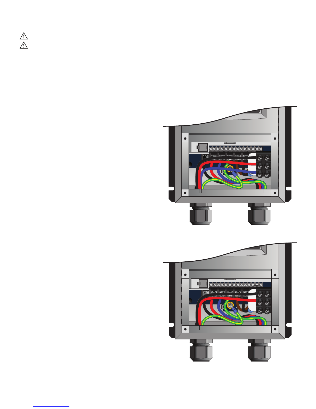
Wiring: 200–250 V, three-phase fan controllers
WARNING: Wait three minutes after disconnecting before servicing!
WARNING: Improper installation can cause electric shock or damage to the motor and controller. A
qualified electrician should perform the installation.
The diagrams below show wiring options for a 200–250 V, 3 Φ fan controller. See “Power Requirements for Fan
Controllers” for detailed power requirements.
Wiring for 200–250 V, 3 Φ, 50/60 Hz fan controllers
A disconnect is included with the fan controller for
200–250 V, 3 Φ. An EMI filter is not included with this
fan controller.
Note: This fan controller does not contain fusing!
Power must be supplied to this controller via
a dedicated circuit breaker or properly fused
disconnect!
AC Input Wiring
3W plus GND
BLK
RED BLU
GRN/YEL
RED
GRN/
YEL
BLK
BLU
Motor Output Wiring
3W plus GND
Optional 1 Φ wiring for 200–250 V, 3 Φ, 50/60 Hz
controllers
The L3 terminal is not used when wiring the fan
controller for 200–250 V, 1 Φ. A disconnect is included
with the fan controller. An EMI filter is not included with
this fan controller.
Note: This fan controller does not contain fusing!
Power must be supplied to this controller via
a dedicated circuit breaker or properly fused
disconnect!
RED
BLK
GRN/YEL
RED
GRN/
YEL
BLK
BLU
30
WWW.BIGASSSOLUTIONS.COM © 2015 DELTA T CORP. ALL RIGHTS RESERVED.
AC Input Wiring
2W plus GND
Motor Output Wiring
3W plus GND
Page 37
U
/T1V/T2W/T3
PE
L1 L2 L3
1 2 5 6 13A13B13C 14 30 16 1725 4 11
1 2 5 6 13A13B13C 14 30 16 1725 4 11
L1
L2
L3
U
/T1V/T2W/T3
PE
L1 L2 L3
1 2 5 6 13A13B13C 14 30 16 1725 4 11
1 2 5 6 13A13B13C 14 30 16 1725 4 11
L1
L2
L3
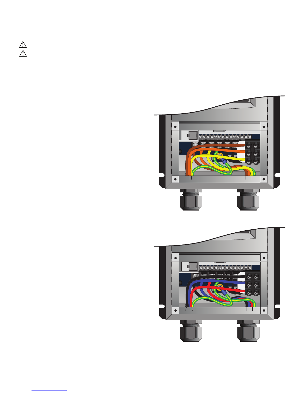
Wiring: 400–480 V & 575–600 V, three-phase fan controllers
WARNING: Wait three minutes after disconnecting before servicing!
WARNING: Improper installation can cause electric shock or damage to the motor and controller. A
qualified electrician should perform the installation.
The diagram below shows wiring options for 400–480 V, 3 Φ and 575–600 V, 3 Φ fan controllers. See “Power
Requirements for Fan Controllers” for detailed power requirements.
Wiring for 400–480 V, 3 Φ, 50/60 Hz fan controllers
An EMI filter and disconnect are included with the fan
controller for 400–480 V, 3 Φ.
Note: This fan controller does not contain fusing!
Power must be supplied to this controller via
a dedicated circuit breaker or properly fused
disconnect!
Wiring for 575–600 V, 3 Φ, 50/60 Hz controllers
A disconnect is included with the fan controller for
575–600 V, 3 Φ. An EMI filter is not included with this
fan controller.
Note: This fan controller does not contain fusing!
Power must be supplied to this controller via
a dedicated circuit breaker or properly fused
disconnect!
GRN/YEL
BRN
AC Input Wiring
3W plus GND
GRN/YEL
ORG GRN/
YEL
BRNORG YEL
YEL
Motor Output Wiring
3W plus GND
BLUBLU GRN/
YEL
BLKBLK
REDRED
WWW.BIGASSSOLUTIONS.COM © 2015 DELTA T CORP. ALL RIGHTS RESERVED.
AC Input Wiring
3W plus GND
Motor Output Wiring
3W plus GND
31
Page 38
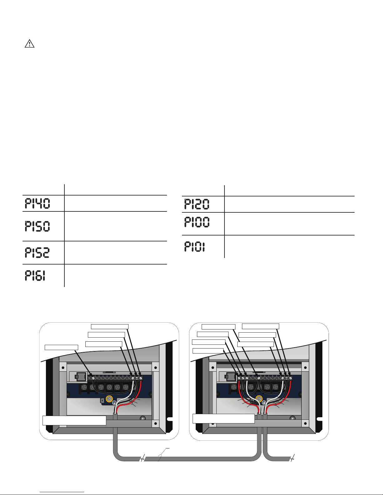
Daisy Chaining
WARNING: Wait three minutes after disconnecting before servicing!
The following illustrations and parameter changes enable daisy chaining of the Pivot fan speed controller.
The first fan provides a start/stop contact and 0–10 VDC analog speed reference for the downstream fan
controller. The downstream fan controller provides a new start/stop contact and 0–10 VDC analog speed
reference for the following downstream fan controller. This preferred method of linking the fan controllers
together ensures minimal signal loss of command signals in larger multi-fan systems.
Assertion Level Switch (ALSW)
The fan controller ships with the onboard digital I/O configured for Sourcing (PNP) operation. Terminal 4 provides
+15 VDC to be used as a supply voltage for user-supplied switches and accessories. For this 3-wire daisy chaining
application, the downstream fan controllers must be switched to Sinking (NPN) operation. Terminal 4 will then
provide a DC common connection and allow the analog signal and start stop signal to share that common. The
Assertion Level Switch above terminal 4 must be switched from (+) to (-) on all downstream fan controllers for
proper daisy chaining operation prior to powerup, parameter changes and operation.
Parameter changes (first controller)
Parameter Description
Relay Output Function
Change from “0” for None to “1” for Run.
TB-30 Output
Change from “0” for None to “1” for
0–10 VDC output (scaled to drive output
frequency).
TB-30 Scaling Frequency
Change to equal the frequency setting
Parameter changes (downstream controllers)
Parameter Description
Assertion Level
Change from “2” for High to “1” for Low.
Start Control Source
Change from “0” for keypad operation to “1” for
Terminal Strip.
Standard Reference Source
Change from “0” for keypad operation to “1” for
0–10 VDC analog input operation.
of P103 Maximum Frequency.
Speed at Max Signal
Change to equal the frequency setting
of P103 Maximum Frequency.
Note: Depending on the AWG and distance of the low voltage wiring, the downstream fans may run slightly slower than the leading fan.
If this occurs, P161 Speed at Max Signal can be used to introduce a minor command reference overshoot to compensate for the analog
voltage drop. At each downstream fan (beginning with the first downstream fan), adjust the value of P161 up 0.1 to 0.2 Hz increments until
the fan’s output frequency matches that of the lead fan.
#17 = N.O. Relay Output
#16 = N.O. Relay Output
#30 = 0–10 VDC Output
#2 = Analog Common
#17 = N.O. Relay Output
#16 = N.O. Relay Output
#30 = 0–10 VDC Output
#4 = Digital Common*
#5 = 0–10 VDC Input
#2 = Analog Common
#1 = Run/Stop Input
1 2 5 6 13A13B 13C 14 30 16 1725 4 11
1 2 5 6 13A13B 13C 14 30 16 1725 4 11
PE
L1 L2 L3
WWW.BIGASSSOLUTIONS.COM © 2015 DELTA T CORP. ALL RIGHTS RESERVED.
32
U/T1 V/T2 W/T3
Terminals 2 and 16 shall all be tied together
on the first fan controller.
RED
BLK
WHT
U/T1 V/T2 W/T3
WHT
Terminals 2, 4, and 16 shall all be tied
together on all downstream fan controllers.
3 conductor shielded cable minimum 20 AWG
Stranded (provided by installer). Recommended
Maximum distance is 200 ft.
1 2 5 6 13A13B 13C 14 30 16 1725 4 11
1 2 5 6 13A13B 13C 14 30 16 1725 4 11
BLK
RED
PE
L1 L2 L3
RED
WHT
BLK
0–10 VDC and Start/Stop out
to next downstream controller
Page 39
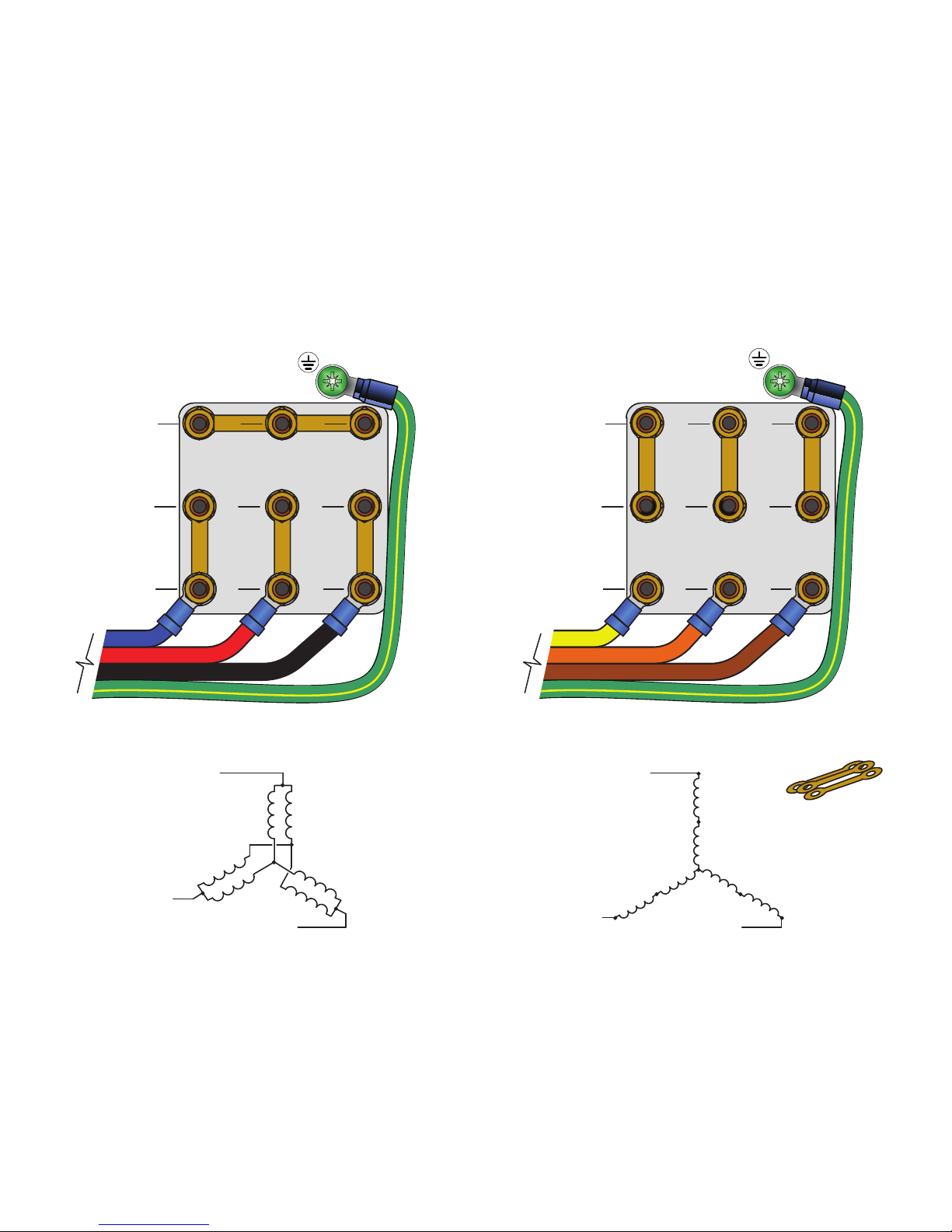
Wiring the fan motor: 9-lead, dual voltage, wye motor
configurations
The motor wiring configurations shown below are applicable to 9-lead dual voltage wye wound motors rated for
230/460 VAC and 330/600 VAC. Consult the motor nameplate and/or wiring placard for verification of required
wiring connections. Motors with terminal blocks require ring terminals and a 7 mm nut driver for termination. The
diagrams below include L2 and L3 swap to yield proper motor rotation. Note: Swapping leads to reverse rotation
is done only on the output side of the drive.
blue
red
black
VAC from VFD
green w/ yellow
Low Voltage
200–240 VAC, 50–60 Hz
330–350 VAC, 50–60 Hz
U2
T4
U5
T7
U1
T1
V2
T5
V5
T8
V1
T2
W2
T6
W5
T9
W1
T3
yellow
orange
brown
VAC from VFD
green w/ yellow
High Voltage
400–480 VAC, 50–60 Hz
575–600 VAC, 50–60 Hz
U2
T4
U5
T7
U1
T1
V2
T5
V5
T8
V1
T2
W2
W5
T9
W1
T3
T6
Low Voltage
WWW.BIGASSSOLUTIONS.COM © 2015 DELTA T CORP. ALL RIGHTS RESERVED.
High Voltage
Jumper bars are
provided with the
motor
33
Page 40
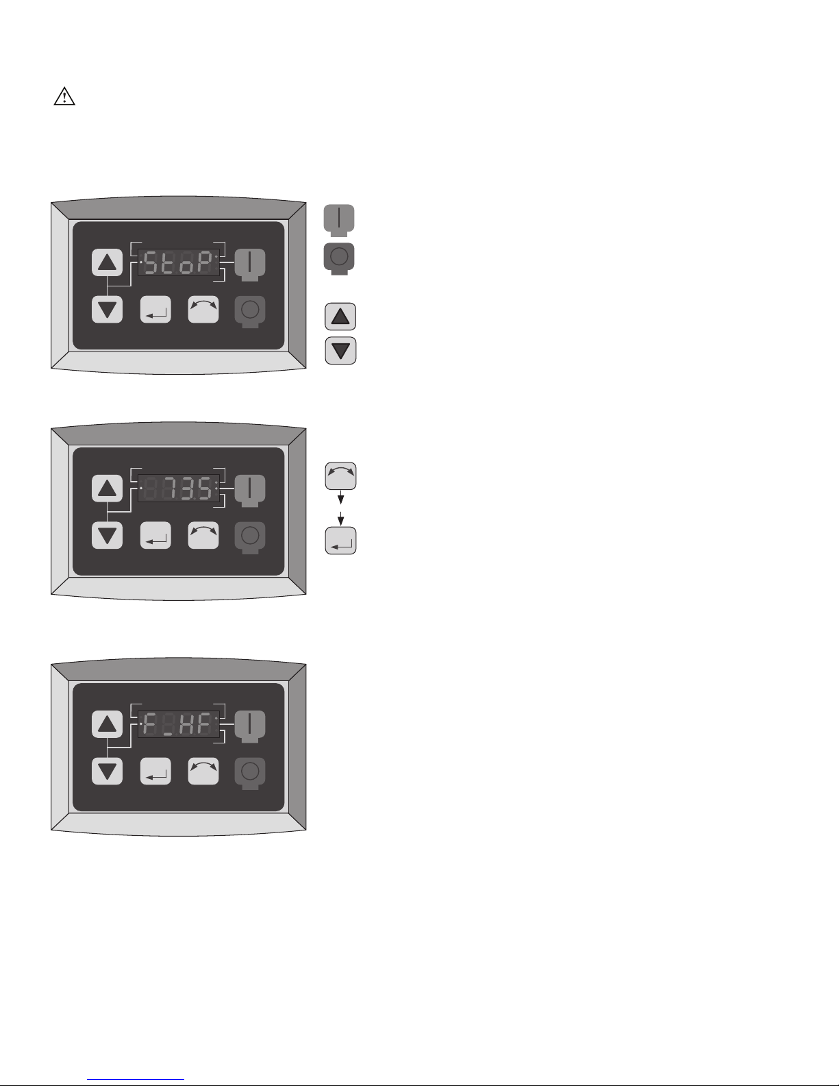
Operating the fan controller
WARNING: The following startup procedures apply to standard model controllers. Procedures may vary
depending on installation options and system automation. The installer should verify proper wiring,
terminations, and proper voltage supply before proceeding. High voltage gloves and arc flash protection
are recommended.
Starting and stopping the fan
AUTO FWD
RUN
REV
RUN
STOP
The RUN and STOP buttons control the fan start and stop
functions. To start the fan, press the green RUN button.
To stop the fan, press the red STOP button.
M
R F
STOP
Drive Idle/Stopped Screen
AUTO FWD
REV
M
R F
RUN
STOP
Fan Speed Percentage Display
(73.5% Running FWD)
AUTO FWD
R F
then
M
Adjusting fan speed
The Arrow buttons control speed adjustment. To adjust
fan speed, press the Up or Down Arrow button. Single
presses will increase or decrease the speed in 1-2%
increments. Pressing and holding the Up or Down Arrow
button will slowly and continuously adjust fan speed until
the button is released.
Reversing direction of fan rotation
The direction of fan rotation can be reversed when the
fan is stopped or running. To reverse the direction of
rotation, press the Direction button, and then press
the Memory/Enter button (as shown on the left). The
associated Direction indicator will flash, indicating the
pending change.
REV
M
R F
RUN
STOP
Typical Fault Message Display
(Incoming Line Over-Voltage Shown)
Note: The fan should rotate in same direction (counterclockwise when viewed from the floor) during both the
warmer and cooler months. If the fan is not rotating in this direction, press the Direction button, and then press
the Memory/Enter button. During the warmer months, run the fan at higher speeds. This will circulate the air and
provide a cooling breeze. During the cooler months, run the fan at lower speeds. This will push warmer air down
from the ceiling to the floor without creating a cooling breeze.
34
WWW.BIGASSSOLUTIONS.COM © 2015 DELTA T CORP. ALL RIGHTS RESERVED.
Page 41
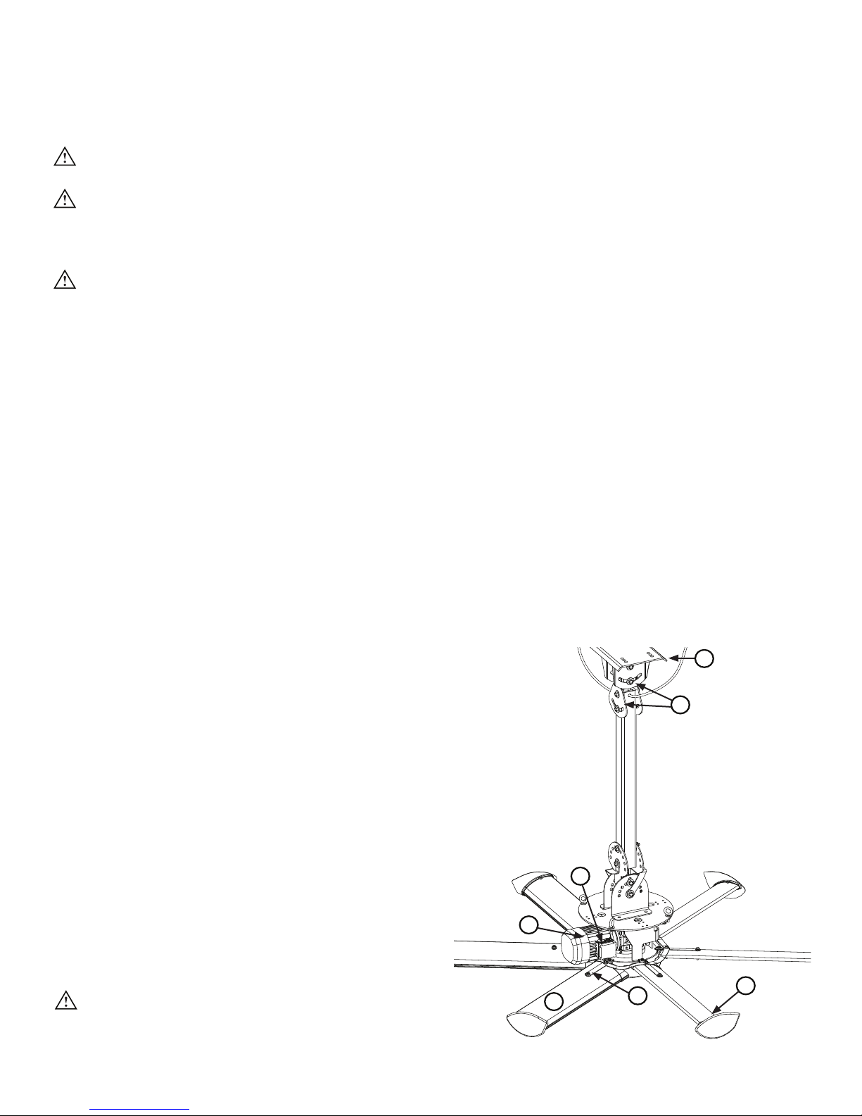
PREVENTIVE MAINTENANCE
1
2
3
4
567
Please take a few moments each year to perform the following preventive maintenance inspection on your fan to
ensure its safe and ecient operation. If you have any questions, please contact Customer Service.
WARNING: Risk of fire, electric shock, or injury to persons during cleaning and user-maintenance!
Disconnect the appliance from the power supply before servicing.
WARNING: Before servicing or cleaning the fan, switch o power at service panel and lock the service
disconnecting means to prevent power from being switched on accidentally. When the service
disconnecting means cannot be locked, securely fasten a prominent warning device (such as a tag) to the
service panel.
WARNING: When service or replacement of a component in the fan requires the removal or disconnection
of a safety device, the safety device is to be reinstalled or remounted as previously installed.
Annual preventive maintenance
Note: Actual installation setup may dier from picture.
To be performed annually (see “Maintenance Checklist”):
1. Ensure safety cable is present and securely tightened. The cable should be tightly wrapped around the mounting
structure with as little slack as possible. The shackle should be located on the topside of the mounting structure.
The shackle’s screw pin should be securely tightened.
2. Ensure all mounting bolts (16x or 12x depending on installation setup) are present and torqued to 40 ft·lb
(54.2 N·m).
3. Inspect motor terminations inside junction box and tighten if necessary.
4. Check gear reducer for oil leakage. If leakage is present, contact Customer Service.
5. Ensure all airfoils are secured to one another by airfoil retainers.
6. Ensure all bolts (18x) securing airfoils to fan are present and torqued to 29 ft·lb (47 N·m).
7. Ensure all screws (10x) securing winglets to airfoils are securely tightened.
8. Check guy wires (if installed) for fraying or damage.
General preventive maintenance
• Dust airfoils, motor, and motor housing. If desired,
use a gentle cleaner or degreasing agent to polish
the airfoils. Do not use Clorox® or other chlorine
based cleaners! This could result in the release of
toxic/fatal fumes.
• Check all fan controller connections and tighten as
needed. Using a vacuum, remove all dust and debris
from the inside and outside of the controller.
• Verify proper fan rotation. To be eective, the fan
must be turning counterclockwise when viewed
from the floor. To change the direction of the
fan’s rotation, see instructions “Operating the fan
controller.”
WARNING: Do not operate a fan with missing or
damaged components! Please contact Customer
Service.
WWW.BIGASSSOLUTIONS.COM © 2015 DELTA T CORP. ALL RIGHTS RESERVED.
35
Page 42

ANNUAL MAINTENANCE CHECKLIST
Fan Model: Fan Model: Fan Model:
Serial #: Serial #: Serial #:
Location: Location: Location:
Date Initials Date Initials Date Initials
36
WWW.BIGASSSOLUTIONS.COM © 2015 DELTA T CORP. ALL RIGHTS RESERVED.
Page 43

TROUBLESHOOTING
WARNING: When servicing or replacement of a component in the fan requires the removal or disconnection
of a safety device, the safety device is to be reinstalled or remounted as previously installed.
WARNING: Risk of fire, electric shock, or injury to persons during cleaning and user-maintenance.
Disconnect fan from power supply before servicing.
WARNING: TO REDUCE THE RISK OF FIRE, ELECTRIC SHOCK, OR INJURY TO PERSONS, OBSERVE THE
FOLLOWING:
• Use this fan only in the manner intended by the manufacturer. If you have questions, contact the
manufacturer.
• Before servicing or cleaning the fan, switch power o at service panel and lock the service disconnecting
means to prevent power from being switched on accidentally. When the service disconnecting means
cannot be locked, securely fasten a prominent warning device, such as a tag, to the service panel.
Customers in the United States
For questions about your product or customer
service inquiries, please call our toll free number
(877-BIG-FANS) or visit www.bigassfans.com/service.
Some issues can be resolved before requesting service. Review the below troubleshooting tips before contacting
Customer Service for support.
Customers outside of the United States
For questions about your product or customer
service inquiries, please contact your local Big Ass
Fans representative or fill out a contact form at
www.bigassfans.com/service.
Symptom Possible Solution(s)
The fan is turning in the wrong direction. To be eective, the fan should be rotating in the counterclockwise
direction when viewed from the floor. If the fan is not rotating in the
counterclockwise direction, press the F/R button on the controller.
A popping noise is coming from the fan.
Airfoil noise comes from airfoils that are
not tightened to the specified torque.
The fan will not start. Verify the following:
The fan controller generates radio
frequency noise (RF).
Fan controllers generate RF noise in many
ways, but this can be prevented using
the proper wiring practices outlined in
“Electrical Installation.”
The motor makes noise when fan speed
is increased.
Disconnect the fan from power, and then tighten the airfoil fasteners
to 29 ft·lb (39.3 N·m). If the popping still occurs, verify that the airfoils
are not contacting each other. If they are, contact Big Ass Fans
Customer Service.
Make sure that all wires are securely connected.
Verify that supply power is adequate and functional.
If the fan still does not start, contact Customer Service.
Verify the following:
Do not run your controller and sensitive equipment on the same
power line.
Install shielded cables, run leads in grounded metallic conduit, or
use appropriate size 4 conductor shielded cable for motor leads.
Ensure proper grounding at the motor, controller, and from the
controller to the utility.
If the noise is still present, contact Customer Service.
Verify motor currents are within limits. See the fan specifications on
page 1.
Audible high frequency carrier noise may
be an indicator of a stall condition.
Note: Some motor, gearbox, or drive noise is to be expected and is normal.
WWW.BIGASSSOLUTIONS.COM © 2015 DELTA T CORP. ALL RIGHTS RESERVED.
37
Page 44

Page 45

WARRANTY RETURN INSTRUCTIONS
Congratulations on your purchase of a Big Ass Fan! We are delighted that you have chosen our product to improve
the quality of your indoor environment, and hope you’ll have much pleasure using the fan for years to come.
Replacement of products under warranty acknowledgment
& return instructions
We have received your request for replacement of a part that failed during normal use and which you believe to
be covered under warranty. We are shipping this replacement part to you pursuant to your notice that you will be
replacing the original part within 10 days.
This replacement part is being shipped to you prior to our receipt of the item that failed, and prior to our evaluation
of this part to determine the reasons for its failure and whether it is covered under warranty.
In order to evaluate the cause of the product failure, we need you to return the original part to our oces within
10 working days of receipt of the replacement part. Should the part be covered under warranty, you will not be
charged for the replacement item. However, you will be charged for the replacement part plus shipping if (1) the
part is not under warranty because the source of failure is outside the scope of the warranty, or (2) the warranty
period has expired. If there is no warranty coverage, we will send you a detailed letter of explanation.
We also will charge you for the replacement item plus shipping and handling if you do not return the original item
within 10 days of the receipt of the replacement item.
Instructions for returning the original item
1. Please use the return label that is included in the box containing the replacement part. The return shipment
address is:
Big Ass Fans
ATTN: RMA#________
800 Winchester Road
Lexington, KY 40505
2. Use the packaging for the replacement part to return the original part.
3. Include the packing list we have provided which includes the RMA#.
4. If the part weighs over 50 lb, you will be provided a prepaid Bill Of Lading. To schedule a freight pick up, please
contact Customer Service. We will only charge back the freight costs if the original part is not under warranty, or
if you do not return the original component within 10 days of receipt of the replacement.
5. If the part weighs 50 lb or less, please use the provided prepaid UPS Ground shipping label and drop o at your
nearest UPS pickup location.
We apologize for the inconvenience, and appreciate your assistance and cooperation. If you have questions,
please contact us at 1-877-BIG-FANS.
Thank you,
Big Ass Fans
WWW.BIGASSSOLUTIONS.COM © 2015 DELTA T CORP. ALL RIGHTS RESERVED.
39
Page 46

Warranty claim form instructions
1. Complete Warranty Claim Form (see following pages) and Responsibility Agreement (see following pages) and
fax them to 859-967-1695, Attn: Customer Service. These pages will be faxed back to you for your records.
The Warranty Claim Form will include our acknowledgment and a Return Materials Authorization (RMA) number.
Note: Do not return any item without first being assigned an RMA# by Big Ass Fans Customer Service.
2. No more than 10 days prior to the date you have made arrangements to replace the component part, call
Customer Service at 1-877-BIG-FANS to arrange for replacement component delivery and original component
pickup. At that time, we will fax you a written acknowledgment of your call that includes a reminder of the
return instructions. Note: Even if you are not able to replace the component immediately following your initial
notice to us, returning the Warranty Claim Form and Responsibility Agreement will eectively stop the warranty
clock from running. You can then make the product exchange when you are prepared to do so. However, the
warranty period will continue to run until we receive these completed pages back from you, and no warranty
will be honored without receipt of these pages within the warranty period. We will not send out any replacement
part until you have called to let us know that you have scheduled installation of the replacement. This ensures
that the replacement part is not lost or damaged while awaiting installation, and that you are not billed for the
replacement because you have waited too long to return the original component (see Responsibility Agreement).
3. When you receive the replacement part, you have 10 working days to remove and replace the existing component
and return it to us at 800 Winchester Road, Lexington, KY 40505.
a. Upon receiving the replacement part, verify that replacement part order is correct. If order is incorrect or
damaged, notify Big Ass Fans within 24 hours after receiving order.
b. Use care unpacking the replacement component, as you will need to use BOTH the packaging from the
replacement part AND the packing list and a return address label included inside this packaging to return
the original part. If the original packaging and return documents are not used, you will be responsible for any
damage incurred in transit as well as any additional costs involved. Note: The RMA# must appear on the
outside of the box being returned. Items without an RMA# will not be accepted.
c. Use the delivery service or one of the truck lines specified in the acknowledgement for return of the part. We
will refuse receipt of any shipment that is returned via an unauthorized carrier. If you prefer, we can make all
arrangements for delivery and pickup.
d. Fax a copy of the bill of lading or other tracking information to 859-967-1695 when the item has been shipped
so that we know to expect delivery of the original part.
4. If we do not receive the original part back within 15 working days from the date you receive delivery of the
replacement, you will be invoiced for the cost of the replacement part, plus freight, on Net 15 terms (see
Responsibility Agreement), and this invoice will be due and payable. If you subsequently return the replacement
part to us after payment has been made, we will refund any payment made for the replacement part, unless we
subsequently determine that the part is not covered under warranty.
40
WWW.BIGASSSOLUTIONS.COM © 2015 DELTA T CORP. ALL RIGHTS RESERVED.
Page 47
2348 Innovation Drive
WARRANTY CLAIM FORM
Name (print): Signature:
Company:
Shipping Address:
City/State/ZIP:
Phone: Fax:
Items Returned:
Reason(s) for Returning Item (please provide detail, including length of time after fan had been in operation that
problem was noticed, nature of problem, any attempts you made to remedy the problem, etc.):
Lexington, KY 40511
Phone: 1-859-233-1271
www.bigasssolutions.com
Date of
Purchase:
ATTENTION: Do not return any item without first being assigned an RMA# by Big Ass Fans Customer Service
Department. The RMA# must appear on the outside of the box being returned. Items without an RMA# will
not be accepted.
Date Replacement Parts
Should Be Shipped (if known):
Acknowledgment of Receipt of Warranty Return Notification
(to be completed by Big Ass Fans)
Acknowledged By: Date:
RMA#:
Authorized Truck Line(s):
WWW.BIGASSSOLUTIONS.COM © 2015 DELTA T CORP. ALL RIGHTS RESERVED.
(Please do not request shipment until you are prepared
to install; you may call us at 1-877-BIG-FANS to arrange
shipment when you have scheduled installation.)
41
Page 48

2348 Innovation Drive
RESPONSIBILITY
Lexington, KY 40511
Phone: 1-859-233-1271
www.bigasssolutions.com
AGREEMENT
To: Big Ass Fans
The undersigned understands and acknowledges receipt of the Warranty Claim Form and Instructions and agrees
that Big Ass Fans has the right, upon receipt of returned merchandise, to make final determination as to whether
this merchandise should be replaced at no cost under Big Ass Fan’s stated warranty policy.
The undersigned further agrees that if Big Ass Fans determines that this merchandise does not qualify under its
stated warranty policy, Big Ass Fans can invoice for the replacement merchandise, plus shipping and handling for
the original part and all replacements, and such invoice will be paid within 15 days of receipt of the same.
The undersigned agrees to ship to Big Ass Fan’s location at 800 Winchester Road, Lexington, KY 40505 all of the
merchandise replaced by Big Ass Fans, including, but not necessarily limited to, defective or failed components,
within 10 working days of the receipt of the any replacements.
The undersigned further agrees that if said replaced merchandise has not been shipped to Big Ass Fans within
10 working days, Big Ass Fans can invoice for the replacement merchandise plus shipping and handling, and the
invoice will be paid within 15 days of receipt.
Signed:
Title:
For:
(Name of Company)
Date:
42
WWW.BIGASSSOLUTIONS.COM © 2015 DELTA T CORP. ALL RIGHTS RESERVED.
Page 49
2348 Innovation Drive
CHECK-IN PROCEDURE
(Big Ass Fans Certified Installers Only)
ATTENTION
These items must be completed prior to any additional installation crew members entering jobsite or any
installation material being unloaded.
Date:
Company: Job Name:
Address: Purchase Order No.:
City/State/ZIP:
Lexington, KY 40511
Phone: 1-859-233-1271
www.bigasssolutions.com
Contact Name:
E-mail:
Phone:
**SEE THE FOLLOWING PAGE FOR NFPA 13 REGULATIONS**
Fan placement is to be in accordance with agreed upon original Scope of Work and Layout. If this is to
change, please note change and consult Field Service Manager for approval.
Installation techniques have been discussed (type of conduit, L-brackets if required, mounting technique
explained). If the extension tubes exceed 4 ft (1.2 m), guy wires are explained and fully understood.
Times in/out, duration, and schedule presented and accepted.
Time (please list the number of employees and total duration of jobs):
Safety rules and regulations have been brought to installer’s attention (e.g., badges, safety harnesses,
vests, hard hats, footwear, lock out/tag out, certification processes, work area free of trash and debris,
etc.). If there are any areas that are forbidden or secure, they are brought to the supervisor’s attention and
instructed not to enter. If there are any special site conditions (i.e., open areas and operating machinery
to be avoided), they are also brought to the supervisor’s attention and instructed how to bypass the area
if required.
Safety Rules and Regulations listed:
The facility manager understands all electrical requirements, i.e., breaker size, voltage, brand, main panel
space, and they are in accordance with original Scope of Work and Layout.
Additional comments:
WWW.BIGASSSOLUTIONS.COM © 2015 DELTA T CORP. ALL RIGHTS RESERVED.
43
Page 50

National Fire Protection Association Standard
In accordance with NFPA 13 Standard from the National Fire Prevention Association as referenced in sections
12.1.4 and 11.1.7: High Volume Low Speed (HVLS) Fans:
The installation of HVLS fans in buildings equipped with sprinklers, including ESFR sprinklers, shall comply with
the following:
• The maximum fan diameter shall be 24 feet (7.3 m).
• The fan shall be approximately centered between four adjacent sprinklers.
• The vertical clearance from the fan to sprinkler deflector shall be a minimum of 3 feet (0.9 m).
• All fans shall be interlocked to shut down immediately upon receiving a water flow signal from the alarm system
in accordance with the requirements of NFPA 72- National Fire Alarm and Signaling Code.
WARNING: The fan should not be installed unless the structure on which the fan is to be mounted is
of sound construction, undamaged, and capable of supporting the loads of the fan and its method of
mounting. Verifying the stability of the mounting structure is the sole responsibility of the customer and/
or end user, and Big Ass Fans hereby expressly disclaims any liability arising therefrom, or arising from
the use of any materials or hardware other than those supplied by Big Ass Fans or otherwise specified
in the installation instructions.
If this installation will be performed outside the scope of work or not within the specifications of Big Ass Fans by
customer’s request, please provide specific details:
Please sign below if both parties agree that all aspects of this installation have been thoroughly explained and are
of clear understanding and agreement of the installation to be completed.
Customer Signature:
Printed Name: Date:
Contractor Signature:
Printed Name: Date:
The supervisor is to hold all documents until the job is complete and send all forms back to Field Service Manager.
This will consist of the service/work order, Check-In document, and Close-Out document. The installation crew will
not receive payment until all forms are signed by the facility manager and the supervisor. These documents will
then be forwarded to the Field Service Manager at Big Ass Fans.
44
WWW.BIGASSSOLUTIONS.COM © 2015 DELTA T CORP. ALL RIGHTS RESERVED.
Page 51
2348 Innovation Drive
CLOSE-OUT PROCEDURE
(Big Ass Fans Certified Installers Only)
Date:
Company: Job Name:
Address: Purchase Order No.:
City/State/ZIP:
Contact Name: Phone:
E-mail:
Lexington, KY 40511
Phone: 1-859-233-1271
www.bigasssolutions.com
**SEE THE FOLLOWING PAGE FOR NFPA 13 REGULATIONS**
The field crew supervisor and facility manager are to walk through the completed installation.
The installation is complete and on time in accordance with the original Check-In document. If not, explain:
Conduit runs are installed in accordance with the Check-In document, Scope of Work, and Layout. If not,
explain:
The fans are correctly placed in accordance with both the Check-In document, Scope of Work, and Layout.
If not, explain:
Breaker size and wire type are in accordance with the Check-In document, Scope of Work, and Layout. If
not, explain:
All safety rules and regulations met in accordance with the Check-In document, Scope of Work, and Layout.
If not, explain:
Fans have been running for over an hour and operate without visible defect or issue.
The fan is spinning in the correct direction (counterclockwise when viewed from floor).
Angle irons are securely fastened and are without any apparent problems in accordance with installation
techniques discussed at check-in.
If extension tube is 4 ft (1.2 m) or longer, guy wires are in place and there is no evidence of a wobble.
Supervisor or contractor has supplied and explained the Installation Guide. If not, explain:
The supervisor or contractor has explained and I understand how to operate fan including starting/stopping,
speed operation, and power disconnect. If not, explain:
Time in/out and duration are in accordance with Check-In document.
Additional comments:
WWW.BIGASSSOLUTIONS.COM © 2015 DELTA T CORP. ALL RIGHTS RESERVED.
45
Page 52
National Fire Protection Association Standard
In accordance with NFPA 13 Standard from the National Fire Prevention Association as referenced in sections
12.1.4 and 11.1.7: High Volume Low Speed (HVLS) Fans:
The installation of HVLS fans in buildings equipped with sprinklers, including ESFR sprinklers, shall comply with
the following:
• The maximum fan diameter shall be 24 feet (7.3 m).
• The fan shall be approximately centered between four adjacent sprinklers.
• The vertical clearance from the fan to sprinkler deflector shall be a minimum of 3 feet (0.9 m).
• All fans shall be interlocked to shut down immediately upon receiving a water flow signal from the alarm system
in accordance with the requirements of NFPA 72- National Fire Alarm and Signaling Code.
WARNING: The fan should not be installed unless the structure on which the fan is to be mounted is
of sound construction, undamaged, and capable of supporting the loads of the fan and its method of
mounting. Verifying the stability of the mounting structure is the sole responsibility of the customer and/
or end user, and Big Ass Fans hereby expressly disclaims any liability arising therefrom, or arising from
the use of any materials or hardware other than those supplied by Big Ass Fans or otherwise specified
in the installation instructions.
NOTE: The customer’s initials are required as acknowledgement for the following instances:
Return Trip Required—Additional Charges Apply (Customer not Ready/Lift Issues)
Work Completed Outside Scope of Work (if applicable)
Installation Not Performed Per BAF Recommendations or Specifications For Any Reason
Customer Understands and Approves Additional Charges As Explained in amount of $ (if
applicable)
Other (Please Explain Below)
If any portion of this installation was performed outside the scope of work or not within the specifications of Big
Ass Fans at any capacity or for any reason, please provide specific details below:
Signatures of both parties are required below to acknowledge that this installation has been completed to customer’s
satisfaction, to activate fan(s) warranty, and to issue payment to contractor (with required documentation):
Customer Signature:
Printed Name: Date:
Contractor Signature:
Printed Name: Date:
The supervisor is to hold all documents until the job is complete and send all forms back to Field Service Manager.
This will consist of the service/work order, Check-In document, and Close-Out document. The installation crew will
not receive payment until all forms are signed by the facility manager and the supervisor. These documents will
then be forwarded to the Field Service Manager at Big Ass Fans.
46
WWW.BIGASSSOLUTIONS.COM © 2015 DELTA T CORP. ALL RIGHTS RESERVED.
Page 53

CONTACT US
Talk to a Big Ass Fan Expert. Call us at at one of the numbers below or visit www.bigasssolutions.com
Customer Service
U.S.A & Rest of the World
2348 Innovation Drive
Lexington, KY 40511
1-877-244-3267
Australia/Oceania
Unit 22, 1029 Manly Road
Tingalpa QLD 4173, Australia
(07) 3292 0100
East Asia
Room 808, Tai Yau Building
181 Johnston Road
Wan Chai, Hong Kong
+852 2836 5808
Canada
6300 Northwest Dr, Unit 3
Mississauga, ON L4V 1J7, Canada
1-844-924-4277
South & Southeast Asia
18 Tampines Industrial Crescent #06-07
Singapore 528 605
+65 6709 8500
Manufacturing & Warranty Contact Information
Manufacturing
2425 Merchant Street
Lexington, KY 40511
1-877-244-3267
Warranty Returns
800 Winchester Road
Lexington, KY 40505
1-877-244-3267
Page 54

Page 55

Page 56

1001010801
Rev. N
2425 Merchant St., Lexington, KY 40511
1 (877) BIG-FANS | WWW.BIGASSFANS.COM
 Loading...