

Big Ass Fans S3127-A2, S3127-X2, S3150-A2, S3150-S0, S3150-X2 Installation Guide
...INSTALLATION GUIDE

Follow the instructions for your mount type. Each mount uses different parts and hardware.
Universal Mount |
Low Profile Mount |
Standard Mount |
Mounting |
Mounting |
Mounting |
Sloped or flat ceilings from 11 to 18 feet |
Flat ceilings as low as 8 feet |
Flat ceilings from 8.5 to 11 feet |
(3.4 to 5.5 meters) |
(2.4 meters) |
(2.5 to 3.4 meters) |
Input Voltage |
Input Voltage |
Input Voltage |
100–240 VAC, 50–60 Hz |
100–240 VAC, 50–60 Hz |
100–240 VAC, 50–60 Hz |
Page 6 |
Page 15 |
Page 22 |
READ AND SAVE THESE INSTRUCTIONS

BEFORE YOU START
Turn Off Power
Contact a licensed electrician if you are uncomfortable performing electrical work. A licensed electrician must install
the fan if required by local code.
 Do not use the fan with a dimmer switch.
 Turn off power at breaker!
Prepare Fan Site
Outlet Box: Make sure your outlet box is suitable for fan support. If there is not an outlet box at the fan location, install one on a ceiling joist or beam.
Concrete Ceiling: Install an anchor hook for the safety cable if required by your local building and safety code. See the following page for installation details.
Wood Ceiling Joist: Attach the mounting plate or mounting bracket directly to the joist using two wood screws (not supplied). Big Ass Fans recommends using corrosionresistant 12-11 x 45 mm hex head timber screws with seal.
Gather Tools
Select Extension Tube (Universal Mount Only)
If your fan uses the universal mount, you will need to select the appropriate extension tube for your ceiling height and slope.
See page 4 for a guide to select the most appropriate extension tube.
HAIKU® BY BIG ASS FANS |
1 |

Concrete Ceiling
Install an anchor hook for the safety cable if required by your local building and safety code.
Low Profile Mount
|
<![if ! IE]> <![endif]>40 mm |
|
100 mm |
| <![if ! IE]> <![endif]>Ø 8 mm (anchor bolt) |
<![if ! IE]> <![endif]>mm |
|
<![if ! IE]> <![endif]>80 |
Ø 14 mm (anchor hook)
Standard Mount
Ø 12–12.5 mm |
|
|
<![if ! IE]> <![endif]>45 mm |
35 mm |
35 mm |
Universal Mount
|
Ø 6 mm |
|
<![if ! IE]> <![endif]>112 mm |
45 mm |
43 mm |
2 |
REV. D | © 2018 BIG ASS FANS | ALL RIGHTS RESERVED |

Low Profile Mount
Drill four Ø 8 mm holes in the pattern shown. The hole depth should not exceed 40 mm. Remove any dust from the holes. Insert four anchor bolts into the holes. Strike the heads of the anchor bolts with a hammer, ensuring the bolt sleeves are flush with the ceiling surface. Position the mounting plate on the anchor bolts. Ensure all four anchor bolts are fully tightened to expand and lock the anchors.
If required by local building and safety codes, install an anchor hook for the safety cable. Drill a Ø 14 mm hole for the anchor hook in the pattern shown. The hole depth should not exceed 50 mm. Remove any dust from the hole, and then insert the anchor hook and fully tighten.
Standard Mount
Drill three Ø 12–12.5 mm holes in the pattern shown. The hole depth should not exceed 35–40 mm. Remove any dust from the holes. Insert three anchor bolts into the holes. Strike the heads of the anchor bolts with a hammer, ensuring the bolt sleeves are flush with the ceiling surface. Position the hanger plate on the anchor bolts. Ensure all three anchor bolts are fully tightened to expand and lock the anchors.
If required by local building and safety codes, install an anchor hook for the safety cable. Drill a
Ø 8–8.5 mm hole for the anchor hook adjacent to the hanger plate. The hole depth should not exceed 35–40 mm. Remove any dust from the hole, and then insert the anchor hook and fully tighten.
Universal Mount
Drill three Ø 6 mm holes in the pattern shown. The hole depth should not exceed 40 mm. Remove any dust from the holes. Insert three anchor bolts into the holes. Strike the heads of the anchor bolts with a hammer, ensuring the bolt sleeves are flush with the ceiling surface. Position the mounting bracket on the anchor bolts. Ensure all three anchor bolts are fully tightened to expand and lock the anchors.
If required by local building and safety codes, install an anchor hook for the safety cable. Drill a Ø 8 mm hole for the anchor hook. The hole depth should not exceed 50 mm. Remove any dust from the hole, and then insert the anchor hook and fully tighten.
| <![if ! IE]> <![endif]>50 mm max |
<![if ! IE]> <![endif]>40 mm max |
| <![if ! IE]> <![endif]>35–40 mm |
<![if ! IE]> <![endif]>35–40 mm |
| <![if ! IE]> <![endif]>50 mm max |
<![if ! IE]> <![endif]>40 mm max |
HAIKU® BY BIG ASS FANS |
3 |

Choosing an Extension Tube (Universal Mount Only)
Consult the tables below to select the appropriate extension tube for your fan.
Ceiling Height
For optimum performance, Big Ass Fans recommends the following extension tube lengths based on ceiling height.
Ceiling Height |
|
Extension Tube Length |
9.5–11 ft |
|
20 in. |
|
||
(2.9–3.4 m) |
|
(508 mm) |
|
|
|
11–13 ft |
|
32 in. |
(3.4–4 m) |
|
(813 mm) |
13–14 ft * |
|
48 in. * |
(4–4.3 m) * |
|
(1219 mm) * |
>14 ft * |
|
60 in. * |
(>4.3 m) * |
|
(1524 mm) * |
|
|
|
*Big Ass Fans recommends using an extended length extension tube for ceiling heights over 13 ft (4 m). The fan comes standard with 20 in. (508 mm) and 32 in. (813 mm) extension tubes. Other lengths are available by contacting Customer Service.
Ceiling Slope
Haiku fans with a universal mount can be installed on sloped ceilings with an angle no greater than 33°.
Fan Diameter |
|
Maximum |
|
Extension Tube |
|
Ceiling Slope |
|
Length |
|
|
|
|
||
52 in. |
|
26° |
|
20 in. |
|
|
|||
(1.3 m) |
|
|
(508 mm) |
|
|
|
|
||
|
|
|
|
|
52 in. |
|
33° |
|
32 in. |
(1.3 m) |
|
|
(813 mm) |
|
|
|
|
||
60 in. |
|
22° |
|
20 in. |
(1.5 m) |
|
|
(508 mm) |
|
|
|
|
||
60 in. |
|
33° |
|
32 in. |
(1.5 m) |
|
|
(813 mm) |
|
|
|
|
||
|
|
|
|
|
84 in. |
|
16° |
|
20 in. |
(2.1 m) |
|
|
(508 mm) |
|
|
|
|
||
84 in. |
|
29° |
|
32 in. |
(2.1 m) |
|
|
(813 mm) |
|
|
|
|
||
|
|
|
|
|
4 |
REV. D | © 2018 BIG ASS FANS | ALL RIGHTS RESERVED |

Haiku Remote
Do not expose the remote control to rain or water.
Turns fan on or off.
Turns light on or off.
Increases fan speed/light brightness.
Decreases fan speed/light brightness.
Sets fan timer length of up to eight hours. Each press extends timer by one hour.
Clears active fan timer.
Varies fan speed to simulate a natural breeze.
Automatically adjusts your fan speed overnight to keep you comfortable while you sleep.
HAIKU® BY BIG ASS FANS |
5 |

<![endif]>Universal Mount
UNIVERSAL MOUNT
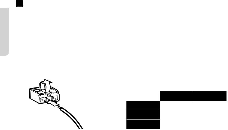
Wire Connectors 

Airfoils (3)
Safety cable not shown
If the EMI filter is included, install it with your fan.
 Mounting Bracket
Mounting Ball
and Wedge
Canopy
Canopy Screws (4) 


 6 mm Steel Pin
Extension Tube
Wiring Cover
M6 x 32 mm Bolt 


 M6 Nut
|
Motor Hub |
|
Grommets (6) |
M5 Screws (6) |
Lower Cover |
6 |
REV. D | © 2018 BIG ASS FANS | ALL RIGHTS RESERVED |
1 |
Install Airfoils |
Remove and recycle the plastic protective cover.
Moving clockwise, align each airfoil on the fan hub and secure it with the airfoil hardware (Fig. 1). Make sure the sticker color on each airfoil matches the corresponding sticker color on the fan hub!
Fig. 1


 M5 Screw
 Grommet
Airfoil
2 |
Install Lower Cover |
If you purchased the fan light kit, proceed to the instructions included with the kit, and then return to these instructions.
Attach the lower cover as shown (Fig. 2).
Fig. 2

 Lower Cover
<![endif]>Mount Universal
HAIKU® BY BIG ASS FANS |
7 |

<![endif]>Universal Mount
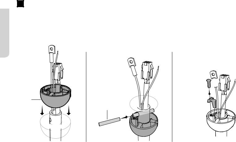
3 |
Attach Extension Tube and Wiring Harness |
Align the holes on the extension tube with the holes on the motor bracket, and then secure the tube with the M6 x 32 mm bolt and M6 nut (Fig. 3.1).
Connect the wiring harness from the extension tube to the receptacle from the motor hub (Fig. 3.2).
Fig. 3.1 |
Fig. 3.2 |
M6 Nut
M6 x 32 mm Bolt
Wiring
 Harness
8 |
REV. D | © 2018 BIG ASS FANS | ALL RIGHTS RESERVED |
4 |
Install Lower Safety Cable and Ground Wire |
Install the safety cable and ground wire lugs with the unpainted screws and lock washers (Fig. 4.1).
Make sure all hardware is secure, and then gently tug the cables at the top of the extension tube to reduce slack (Fig. 4.2).
Slide the wiring cover down the extension tube, resting it on the fan hub. Make sure no wires are visible between the cover and fan hub. Slide the canopy down the extension tube (Fig. 4.3).
Fig. 4.1 |
Fig. 4.2 |
Fig. 4.3 |
|
|
|
Ground Wire
(Green)


 Canopy Safety Cable


Wiring
Cover
Lock
 Washer Screw
<![endif]>Mount Universal
HAIKU® BY BIG ASS FANS |
9 |
<![endif]>Universal Mount
5 |
Install Mounting Ball |
Slide the mounting ball over the extension tube (Fig. 5.1).
Insert the 6 mm steel pin into the hole at the top of the extension tube, and then slide the mounting ball upward, seating the steel pin in the inner slots (Fig. 5.2).
Insert the wedge into the mounting ball and secure it with the screw. Tighten the screw enough to prevent movement between the mounting ball and extension tube, but do not over-tighten (Fig. 5.3).
Fig. 5.1
Mounting
Ball
Extension |
Tube |
Fig. 5.2 |
Fig. 5.3 |
Screw 


Wedge 


 6 mm Steel Pin


10 |
REV. D | © 2018 BIG ASS FANS | ALL RIGHTS RESERVED |

6 |
Install Mounting Bracket |
 Disconnect power to the fan location before installing the mounting bracket!
Secure the mounting bracket to the mounting structure with suitable hardware (Fig. 6).
Outlet box shown. Your mounting structure may differ from the illustration.
Fig. 6

 Mounting
Bracket


 Suitable Mounting
Hardware
7 |
Hang Fan |
Raise the fan to the mounting bracket. Align the rib in the |
<![if ! IE]> <![endif]>Universal |
|
mounting bracket with the slot in the mounting ball, position |
||
|
||
the mounting ball, and let the fan hang freely (Fig. 7). |
|
|
Gently twist the extension tube to ensure it is properly seated |
|
|
and will not move during fan operation. |
<![if ! IE]> <![endif]>Mount |
|
|
Fig. 7 

|
Mounting |
Mounting |
Bracket |
Ball |
|
HAIKU® BY BIG ASS FANS |
11 |
<![endif]>Universal Mount
8 |
Wire the Fan |
 Disconnect power to the fan location before wiring the fan!
 Do not connect the fan to a damaged power source! Do not attempt to resolve electrical failures on your own. Consult a qualified electrician if uncertain of the electrical installation of this fan.
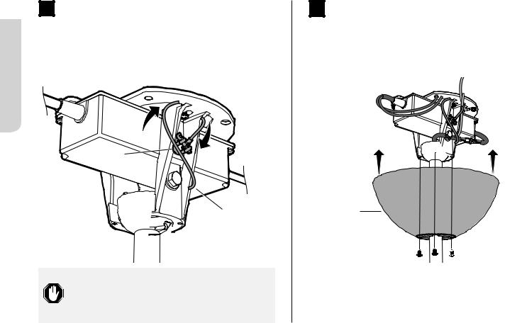
Wire the fan as shown in the diagram using the wire connectors (Fig. 8). If your fan packaging included an EMI filter, install it as shown.
Attach the green ground wire to the mount with the unpainted screw. Connect the wiring harness from the power supply to the wiring harness from the extension tube, making sure that the wiring and safety cable are routed in the same direction.
Fig. 8
|
North America |
|
All other regions |
|
100–120 V |
|
|
|
|
|
|
AC Hot/L1 |
Black |
|
Brown |
|
|||
Brown |
|
||
|
|
|
|
AC Neutral/L2 |
White |
|
Blue |
Blue |
|
||
|
|
|
|
PE/Earth Ground |
Green or Bare |
|
Green with Yellow |
Green with Yellow |
Copper |
|
|
|
|
12 |
REV. D | © 2018 BIG ASS FANS | ALL RIGHTS RESERVED |

Wiring Diagram |
|
|
Wiring Diagram |
(No EMI Filter) |
|
|
(With EMI Filter) |
|
|
BLACK |
WHITE |
|
|
|
|
|
|
|
GREEN & |
|
|
|
YELLOW |
BLACK |
GREEN & |
|
BROWN |
WHITE |
|
||
BLUE |
|
||
YELLOW |
|
||
|
|
||
|
|
EMI FILTER |
|
BROWN |
|
|
|
|
BLUE |
|
|
<![endif]>Mount Universal
HAIKU® BY BIG ASS FANS |
13 |
9 |
Secure Safety Cable |
| <![if ! IE]> <![endif]>Mount |
Loop the safety cable around the mounting bracket or building |
|
structure, and then secure it with the shackle (Fig. 9). |
||
|
||
| <![if ! IE]> <![endif]>Universal |
Fig. 9 |
|
|
||
|
Shackle |
Safety Cable
Canada: The safety cable must be secured directly to an existing part of the building structure. It may be necessary to install additional structural material to provide attachment points.
10 |
Raise Canopy |
Raise the canopy to the mounting bracket, aligning the four holes on the canopy with the holes on the bracket. Secure the canopy to the mounting bracket with the painted screws (Fig. 10). Make sure all wires and the safety cable are tucked in the canopy.
Fig. 10
Canopy


 Canopy Screw
Congratulations!
Installation is now complete. Test your fan using the remote control.
14 |
REV. D | © 2018 BIG ASS FANS | ALL RIGHTS RESERVED |

LOW PROFILE MOUNT
Rubber Bumpers (2) |
Mounting Plate |
Mounting Brackets (2) |
|
6 mm Nylock Nuts (4) |
|
Wiring Cover Screws (2) |
|
|
Wiring Cover |
Extension Tube Screw Caps (2) |
Wiring Cover Trim |
Wire Connectors |
|
|
Motor Hub |
Airfoils (3)


 Grommets (6)

 M5 Screws (6)
Lower Cover
Use the extension tube screw caps that match the color of your fan.
Safety cable not shown.
<![endif]>Mount Profile Low
HAIKU® BY BIG ASS FANS |
15 |

<![endif]>Low Profile Mount
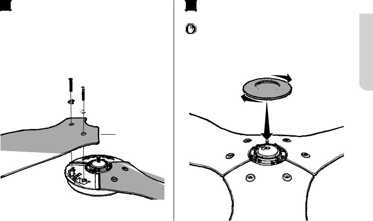
1 |
Install Mounting Plate and Single Bracket |
Slide the rubber bumpers onto the extension tube brackets (Fig. 1.1).
Secure the mounting bracket to the mounting structure with suitable hardware (Fig. 1.2). Your mounting structure may differ from the illustration.
Loosely attach one mounting bracket to the mounting plate with two 6 mm nylock nuts, but do not fully tighten (Fig. 1.3).
Fig. 1.1 |
Fig. 1.2 |
Fig. 1.3 |
Extension Tube Brackets
Rubber
Bumper
Mounting
Plate

 Suitable Mounting
Hardware
Outlet box shown. Your mounting structure may differ from the illustration.
Mounting Plate
6 mm Nylock Nut
16 |
REV. D | © 2018 BIG ASS FANS | ALL RIGHTS RESERVED |

2 |
Secure Safety Cable |
Raise the fan to the bracket and temporarily rest one rubber bumper in the space between the bracket and plate (Fig. 2.1). While supporting the fan, loop the safety cable around the mounting plate or building structure, and then secure it with the shackle (Fig. 2.2).
Fig. 2.1 |
Fig. 2.2 |
Mounting
Plate
Safety
Cable
Shackle
<![endif]>Mount Profile Low
Canada: The safety cable must be secured directly to an existing part of the building structure. It may be necessary to install additional structural material to provide attachment points.
HAIKU® BY BIG ASS FANS |
17 |

<![endif]>Low Profile Mount
3 |
Wire Fan |
Wiring Diagram |
 Disconnect power to the fan location before wiring the fan!
 Do not connect the fan to a damaged power source! Do not attempt to resolve electrical failures on your own. Consult a qualified electrician if uncertain of the electrical installation of this fan.
Allow the fan to hang from the safety cable. Wire the fan as shown in the diagram using the wire connectors (Fig. 3).
BLACK
 GREEN & WHITE
 YELLOW
Fig. 3
BLUE
BROWN
|
North America |
|
All other regions |
|
100–120 V |
|
|
|
|
|
|
AC Hot/L1 |
Black |
|
Brown |
|
|||
Brown |
|
||
|
|
|
|
AC Neutral/L2 |
White |
|
Blue |
Blue |
|
||
|
|
|
|
PE/Earth Ground |
Green or Bare |
|
Green with Yellow |
Green with Yellow |
Copper |
|
|
|
|
18 |
REV. D | © 2018 BIG ASS FANS | ALL RIGHTS RESERVED |
4 |
Install Mounting Brackets |
Raise the fan to the mount. Insert one rubber bumper between the mounting plate and the loosely installed mounting bracket with the 6 mm nylock nuts.
Secure the other bumper with the remaining mounting bracket and nuts (Fig. 4).
Tighten all hardware.
Fig. 4
Mounting 


 Bracket


6 mm Nylock 


 Nut
Nut 
5 |
Install Wiring Cover |
Raise the wiring cover, allowing about a 1/8” (3 mm) gap at the ceiling. Align the mounting slots with the screw holes on the extension tube, and secure it with the wiring cover screws.
Slide the trim up the extension tube, aligning the tabs on the inside with the slots on the bottom of the wiring cover. Twist clockwise to snap the trim into position (Fig. 5).
Fig. 5
Wiring
Cover
Screw |
|
|
|
|
|
|
|
|
|
|
|
Wiring Cover |
|
Screw |
|
|
|
|
|
Trim |
|
|
|
<![endif]>Mount Profile Low
HAIKU® BY BIG ASS FANS |
19 |

<![endif]>Low Profile Mount
6 |
Install Airfoils |
Moving clockwise, align each airfoil on the fan hub and secure it with the airfoil hardware (Fig. 6). Make sure the sticker color on each airfoil matches the corresponding sticker color on the fan hub!
Fig. 6
Airfoil

 Grommet
Remove and recycle the |
M5 Screw |
plastic protective cover. |
|
7 |
Install Lower Cover |
If you purchased the fan light kit, proceed to the instructions included with the kit, and then return to these instructions.
Attach the lower cover as shown (Fig. 7).
Fig. 7

 Lower Cover
20 |
REV. D | © 2018 BIG ASS FANS | ALL RIGHTS RESERVED |
Congratulations!
Installation is now complete. Test your fan using the remote control.
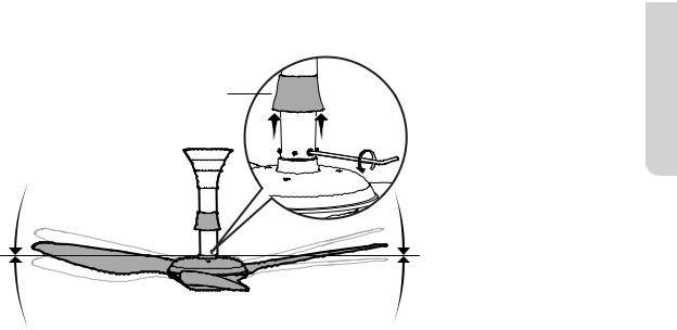
 If your fan appears slightly tilted, raise the lower motor cover trim and locate the pivot bolt. Loosen the bolt with a 5 mm hex key to allow the fan to hang straight, and then re-tighten.
Lower Motor Cover Trim
<![endif]>Mount Profile Low
HAIKU® BY BIG ASS FANS |
21 |

<![endif]>Standard Mount
STANDARD MOUNT
|
|
Mounting Bracket |
|
Mounting Brace Brackets (2) |
M6 Nut |
|
M6 x 25 mm Screw |
|
|
|
|
|
Rubber Bushing |
8 mm Lock Washer |
|
8 mm Flat Washer |
|
|
2 mm x 2 mm Split Pin |
|
|
|
|
|
M8 Bolt |
M8 Nut |
|
|
|
|
Wiring Cover Screws |
Wiring Cover |
|
|
|
Wire Connectors |
|
Wiring Cover Trim |
|
|
Motor Hub |
|
Airfoils (3) |
|
|
|
Grommets (6) |
|
|
M5 Screws (6) |
|
|
Lower Cover |
Use the extension tube screw caps that match the color of your fan.
Safety cable not shown.
22 |
REV. D | © 2018 BIG ASS FANS | ALL RIGHTS RESERVED |

1 |
Install Mounting Bracket |
Seat the rubber bushing in the mounting bracket (Fig. 1).
Secure the mounting bracket to the mounting structure with suitable hardware (Fig. 1). Your mounting structure may differ from the illustration.
Fig. 1
|
Mounting |
|
Bracket |
|
Suitable |
|
Mounting |
Rubber |
Hardware |
Bushing |
|
Outlet box shown. Your mounting structure may differ from the illustration.
2 |
Secure Mount Brace Brackets |
Loosely install the mount brace brackets with the provided hardware (Fig. 2). The bolt should be inserted in the middle hole. Do not fully tighten the hardware.
Fig. 2
M6 x 25 mm Screw
<![if ! IE]><![endif]>Mount Standard
Mount Brace |
M6 Nut |
|
|
Bracket (2) |
|
HAIKU® BY BIG ASS FANS |
23 |

<![endif]>Standard Mount
3 |
Hang Fan |
Raise the extension tube to the mount, and insert the extension tube brackets between the mount brackets and the rubber bushing so that the mounting holes are aligned. Secure the extension tube with the mounting hardware (Fig. 3).
Fully tighten all hardware until the brackets slightly compress the rubber bushing.
Fig. 3 |
Flat Washer |
|
|
|
|
|
|
|
|
Lock Washer |
|
|
M8 Bolt |
|
Split |
|
|
M8 Nut |
|
|
Brackets |
Pin |
|
Wiring Cover 


Extension Tube
Wiring Cover Trim
4 |
Secure Safety Cable |
While supporting the fan, loop the safety cable around the mounting bracket or building structure, and then secure it with the shackle (Fig. 4).
Fig. 4
Safety |
Shackle |
Cable |
Canada: The safety cable must be secured directly to an existing part of the building structure. It may be necessary to install additional structural material to provide attachment points.
24 |
REV. D | © 2018 BIG ASS FANS | ALL RIGHTS RESERVED |

5 |
Wire Fan |
 Disconnect power to the fan location before wiring the fan!
 Do not connect the fan to a damaged power source! Do not attempt to resolve electrical failures on your own. Consult a qualified electrician if uncertain of the electrical installation of this fan.
Wire the fan as shown in the diagram using the wire connectors (Fig. 5).
Wiring Diagram
BLACK |
|
|
|
|
|
GREEN & |
|
|
|
|
|
||
|
|
|
|
|
|
|
WHITE |
|
|
|
|
YELLOW |
|
|
|
|
|
|
||
Fig. 5
BLUE
BROWN
|
North America |
|
All other regions |
|
100–120 V |
|
|
|
|
|
|
AC Hot/L1 |
Black |
|
Brown |
|
|||
Brown |
|
||
|
|
|
|
AC Neutral/L2 |
White |
|
Blue |
Blue |
|
||
|
|
|
|
PE/Earth Ground |
Green or Bare |
|
Green with Yellow |
Green with Yellow |
Copper |
|
|
|
|
<![endif]>Mount Standard
HAIKU® BY BIG ASS FANS |
25 |

<![endif]>Standard Mount
6 |
Install Wiring Cover and Trim |
Raise the wiring cover, allowing about a 1/8” (3 mm) gap at the ceiling. Align the mounting slots with the screw holes on the extension tube, and secure it with the wiring cover screws.
Slide the trim up the extension tube, aligning the tabs on the inside with the slots on the bottom of the wiring cover. Twist clockwise to snap the trim into position (Fig. 6).
Fig. 6
Wiring Cover 
Screw
Screw
Wiring Cover Trim
7 |
Install Airfoils |
Remove and recycle the plastic protective cover.
Moving clockwise, align each airfoil on the fan hub and secure it with the airfoil hardware (Fig. 7). Make sure the sticker color on each airfoil matches the corresponding sticker color on the fan hub!
Fig. 7
Airfoil
Grommet
M5 Screw 


26 |
REV. D | © 2018 BIG ASS FANS | ALL RIGHTS RESERVED |
 Loading...