


22-27
Table of Contents
1 INTRODUCTION ...................................................................................................... 2
Company presentation .......................................................................................... 2
Product presentation ............................................................................................. 2
2 TECHNICAL SPECIFICATIONS .................................................................................. 3
3 DIMENSIONAL DIAGRAMS ..................................................................................... 4
4 GENERAL DESCRIPTION .......................................................................................... 5
5 MAIN COMPONENTS.............................................................................................. 6
6 SAFETY FEATURES ................................................................................................ 15
Safety support ...................................................................................................... 15
Location of the decals on the trailer .................................................................... 15
Presentation of decals ......................................................................................... 16
7 COUPLING/UNCOUPLING THE TRAILER ............................................................... 21
Safety aspects when coupling/uncoupling .......................................................... 21
COUPLING TO TRACTOR ....................................................................................... 22
8 DRIVING THE TRAILER .......................................................................................... 23
Safety aspects when driving ................................................................................ 23
ROAD DRIVING INSTRUCTIONS ............................................................................ 24
Load on towing eyelet and coupling .................................................................... 25
Working under extreme conditions ..................................................................... 26
EXCHANGE MECHANISM ..................................................................................... 27
9 EXCHANGE OPERATION ....................................................................................... 28
Safety aspects during exchange operation .......................................................... 28
Exchange procedure ............................................................................................ 29
10 TIPPING OPERATION ............................................................................................ 32
11 WIRING DIAGRAM ................................................................................................ 33
12 HYDRAULICS CHART ............................................................................................. 36
13 CARRYING OUT SERVICE/MAINTENANCE ............................................................ 37
14 MAINTENANCE/SERVICE ...................................................................................... 39
15 SPARE PARTS ........................................................................................................ 46
16 TROUBLESHOOTING ............................................................................................. 53
17 EC DECLARATION (sample) .................................................................................. 54
CONTACT INFORMATION:
Factory:
AS FORS MW
Tule 30
765 05 Saue
Estonia
Tel: + 372 679 00 00
Fax: + 372 679 00 01
E-mail:
info@forsmw.com
Aftermarket:
We speak English and Swedish.
FMW Farma Norden AB
Hornsväg 2
SE-605 97 Norrköping
Sweden
Tel: + 46 (0) 11 657 70
Fax: + 46 (0) 11 283 70
E-mail:
aftermarket@forsmw.com
© V7.1-2015W42–en Fors MW Ltd www.forsmw.com 1

22-27
1 INTRODUCTION
Stringent demands are placed on manufacturers to comply with the directives for
the product they produce. This product is covered by the Machinery Directive and
the CE marking indicates that it meets the requirements of the Directive. On delivery
of a product, the dealer is required to provide operating instructions for the product.
Company presentation
AS FORS MW was established in Estonia in 1992. The company develops,
manufactures, markets and sells, via dealers, its three market-leading brands. These
are BIGAB hook lift trailers and dump trailers, FARMA lumber trailers and cranes, and
NIAB tractor processors. The company comprises the parent company AS FORS MW,
as well as the subsidiary companies Farma Norden AB (Norrköping, Sweden) and
ForsMW/China. You can find out more about the product you have selected and our
20-year journey by visiting our websitewww.forsmw.com and our blog
www.forsmw.blogspot.com
Product presentation
The BIGAB hook lift exchange system includes a range of models, all offering the
same high level of versatility. A wide and varied range of accessories is also available.
The versatility lies in its ability to handle different kinds of loads on one and the same
chassis. You will find your BIGAB indispensible for a wide range of tasks.
The 22 – 27 is our largest hook lift trailer. Simple, impressive and powerful are all
fitting ways to describe the BIGAB 22 – 27. This is the ideal trailer for transporting
particularly heavy loads. For your safety, it is extremely important that you follow
the instructions in this instruction manual for your BIGAB model.
© V7.1-2015W42-en Fors MW Ltd www.forsmw.com
2

Brakes:
Hydraulic drum
*
Depending on
Pressure & return, 1 single
-
action brake/
Load on towing eyelet:
/REF:150706
22-27
2 TECHNICAL SPECIFICATIONS
Hook lift trailer 22-27
Frame: Rectangular sections 300*100
Bogie: Parabolic sprung triple axles Axle distance 1525 mm
Hubs: 130*130, 10 bolts
Tyres: 560/60-22.5
market
Towing eyelet: For hitch hook
Stabiliser legs: Manual Yes
Light system: 12 volt Yes
Tractor hydraulics: *For brakes
Oil volume: With full system 23 l
Oil volume: Press 89 l, draw 66 l
Oil flow: 60-120 l/min
Max working pressure: Max. 22 MPa
Tipping angle: 50 degrees
Chassis weight (±1%): Standard equipped 6600 kg
Chassis length (±50mm): 7550 mm
Distance eyelet to centre tridem (±20mm): Centered tridem axle 5155 mm
Distance eyelet to ground surface: Min. 475 mm
Height unloaded: 1330mm excl. load carrier frame
1 double-action with floating position
406*120 on 6 wheels
Width across wheels (±30mm): 2590 mm
Bridge length: 5700-6500 mm
Total weight (±1%): 28 600 kg
Max. load incl. bridge: tipping (±1%): 22 000 kg
Max. load incl. bridge: roll on/roll off (±1%): 21 000 kg
Depending on the position of the trailer bed
Max. speed 40 km/h
REF: 150923
2500 – 3500 kg
© V7.1-2015W42-en Fors MW Ltd www.forsmw.com
3

3 DIMENSIONAL DIAGRAMS
22-27
© V7.1-2015W42-en Fors MW Ltd www.forsmw.com
4

Chassi
Hook
Wheels
Towing
22-27
4 GENERAL DESCRIPTION
The trailer is steady when used for both tipping and exchanging. The trailer is
equipped with a torsional parabolic spring bogie on three axles with brakes on all
wheels.
Steering
roller
Rear
Hook
Telescop
Stabilise
Exchange
Tipping
position
© V7.1-2015W42-en Fors MW Ltd www.forsmw.com
5

Rear frame
22-27
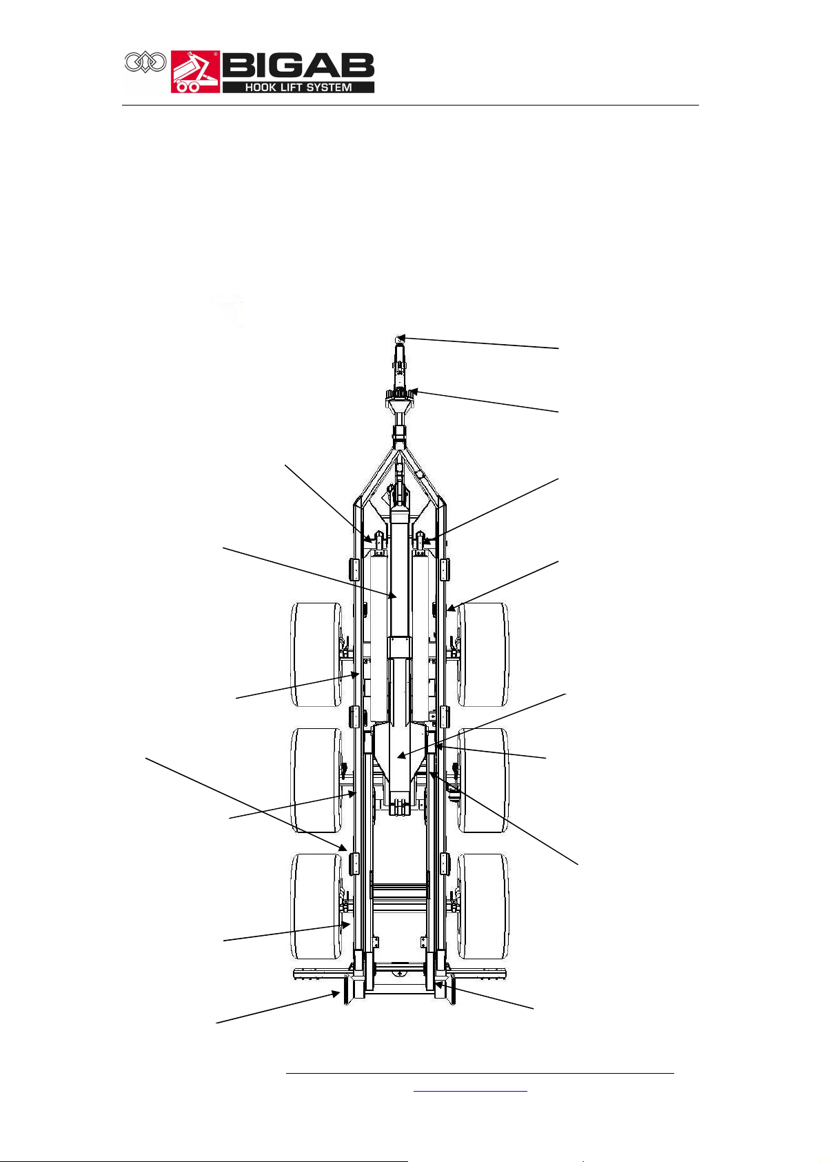
5 MAIN COMPONENTS
The trailer comprises the following principal components and functional devices.
Chassis
Side
Rear beam
Suspension
Rear frame
Bracket for frame
© V7.1-2015W42-en Fors MW Ltd www.forsmw.com
6

Brake cylinder
x 3
bogie
Telescope
Hydraulic cylinder (inside)
Hook frame
Hook
22-27
Hook
frame
Extended tower
1300 mm
Bogie
The trailer is equipped with a powerful sprung tridem bogie with brakes on all six
wheels.
Sprung tridem
Axle with brake
© V7.1-2015W42-en Fors MW Ltd www.forsmw.com
7

Stabiliser leg
Pin
Chassis
Standard height: 1450
Standard height: 1570
Hook
The trailer is equipped with an adjustable hook for two different heights.
22-27
Stabiliser leg
The stabiliser leg is designed to support the trailer when not in use. The stabiliser leg
must not be used when the trailer is loaded. The stabiliser leg must be raised and
secured in place with the pin before moving off.
© V7.1-2015W42-en Fors MW Ltd www.forsmw.com
8

Locking bolt
Chassis
Towing eyelet
Hydraulic cylinder
Locking lug
Exchange unit
The unit is designed for
the procedure when switching between
tipping and exchange.
The lever is located in the middle
of the rear frame.
Exchange unit container lock
The trailer is equipped with a
hydraulic container lock
that secures the container to the frame
Rear frame
22-27
Hydraulic cylinder
Towing eyelet
The towing eyelet is adapted to the hitch on the towing vehicle. It is extremely
important that the towing eyelet is inspected for defects every time the trailer is
used.
© V7.1-2015W42-en Fors MW Ltd www.forsmw.com
9

Rear beam
Steering roller Left/Right
Chassis
Drawbar
The drawbar is used for coupling other equipment to the trailer. It is also used for
attaching the warning triangle. Note! Do not couple excessively heavy loads to the
drawbar. The maximum permitted trailer weight is 10 tonnes.
Steering rollers
The steering rollers are designed to guide the bed correctly. The bed frame must be
inside the steering rollers during exchange operations.
Pin
22-27
© V7.1-2015W42-en Fors MW Ltd www.forsmw.com
10
Frame lock
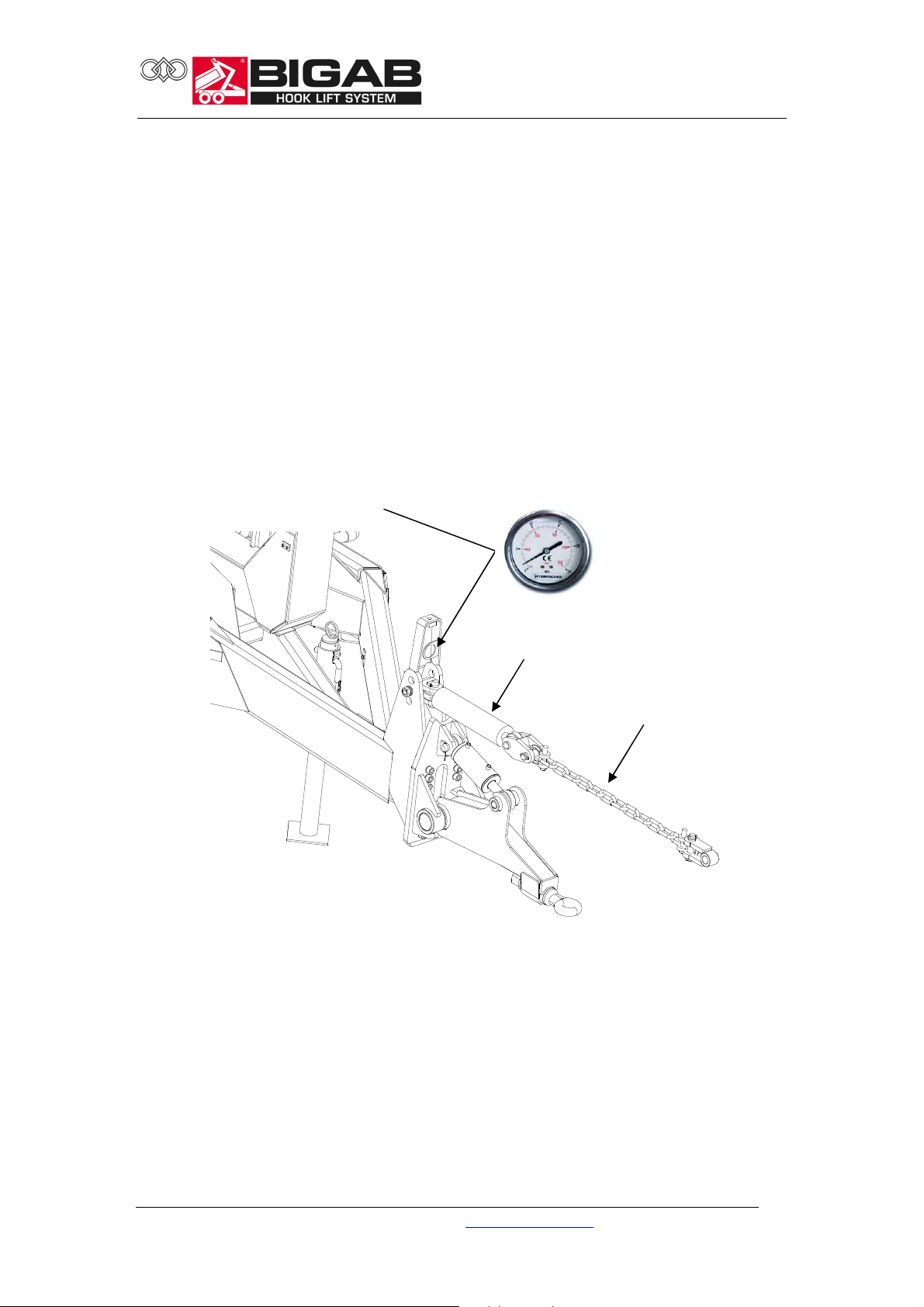
The hydraulic frame lock is used to lock the frame during heavy exchange operations.
When mounting the chain on the tractor for the first time, adjust the length of the
chain so that it is slack when the cylinder is half extended.
When you then tension the cylinder, the pressure relief valve is set at about 100 bar
and it can be adjusted to the size of the tractor.
It is very important to slacken it after exchanging so as not to impede the tractor
during transport.
22-27
Frame lock hydraulic
cylinder
Chain to tractor
© V7.1-2015W42-en Fors MW Ltd www.forsmw.com
11

Suspended drawbar
22-27
Drawbar functions
The trailer is equipped with an adjustable drawbar that can be used for the following
three functions. Use the position switch on the control unit to regulate the drawbar.
Select a function and regulate the pressure with the toggle switch.
Suspended drawbar
Set the mode switch to suspension mode and then apply pressure. Watch the
manometer to see how much pressure you apply. The valve has a pressure
limiter that controls the amount of pressure you can apply. Check at regular
intervals during transport that the pressure remains constant.
Fixed drawbar
This function is used to stabilise the trailer when exchanging containers. Set the
mode switch to fixed mode and apply pressure to stabilise the drawbar.
Swinging drawbar
Set the mode switch to swinging mode. No pressure is applied to the drawbar.
© V7.1-2015W42-en Fors MW Ltd www.forsmw.com
12
Tyres
List of standard tyres and alternative tyres that are used for the different trailer
models.
Model
22-27 560/60-22.5 3.6 40
445/65R-22.5 5-10 40
650/50R-22.5 TL
* The air pressure may vary slightly depending on the make of tyre. Contact the tyre
manufacturer for exact air pressures.
Hydraulic system
The trailer is equipped with a hydraulic system for the various work operations. For
more information, see the Hydraulics Chart chapter.
Electrical system
The trailer has a 12 volt electrical system. For more information, see the Wiring
Diagram chapter.
Brake system
The trailer is equipped with a hydraulic brake system. A pneumatic brake system is
also available as optional equipment. Note! The hydraulic pressure in the brake lines
should not exceed 16 Mpa. Too much hydraulic pressure can cause the brake arm
cam to go over-centre and lock the brakes.
Standard tyres Alternative tyres Air pressure
(bar)
4.0 40
10B -70
22-27
Speed
(km/h)
© V7.1-2015W42-en Fors MW Ltd www.forsmw.com
13

No. Description
1 Tipping/Exchange
2 Telescope in/out
3 Exchange/tip/container lock
4 Frame lock
5 Hydraulic outlet
6 Suspended drawbar up
-
down
7 Suspended drawbar locked
-
sprung
-
floating
8 On-Off
22-27
Electric on-off control
The trailer is equipped with a hydraulic system that is operated via a control unit.
With regard to position 3, it is important to run this function until the signal lights
come on. This indicates that the locks have reached their end stop position.
With regard to position 3, it is important to run
this function until the signal lights come on.
This indicates that the locks have reached their
end stop position.
© V7.1-2015W42-en Fors MW Ltd www.forsmw.com
14
22-27
6 SAFETY FEATURES
Safety support
Always use the safety support when carrying out service work when the trailer bed is
raised. The safety support must not, under any circumstances, be used when the
trailer bed is loaded.
Chassis
Safety support
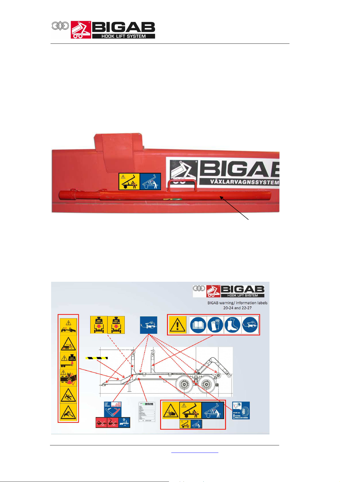
Location of the decals on the trailer
The trailer is marked with various signs relating to safety and information. Check that
all signs are correctly positioned.
© V7.1-2015W42-en Fors MW Ltd www.forsmw.com
15

22-27
Presentation of decals
WARNING!
Warning triangle and instruction manual decal.
The trailer has a warning triangle next to the instruction manual decal to emphasis
the importance of reading the entire instruction manual carefully before using the
trailer. Failure to observe this may result in serious or fatal injury.
INFORMATION!
Decal for the use of safety equipment.
These decals encourage the use of appropriate safety equipment in order to avoid
injury when using the trailer.
DANGER!
Risk of crushing injuries
There is a risk of trapping and crushing injuries during work and maintenance.
WARNING!
Hazardous area
Standing between the trailer and the towing vehicle when the trailer is being driven,
moved with frame steering or when other functions are activated between the
trailer and towing vehicle, can be potentially fatal. As the driver, you must always
ensure that no one is in the area around the machinery.
© V7.1-2015W42-en Fors MW Ltd www.forsmw.com
16

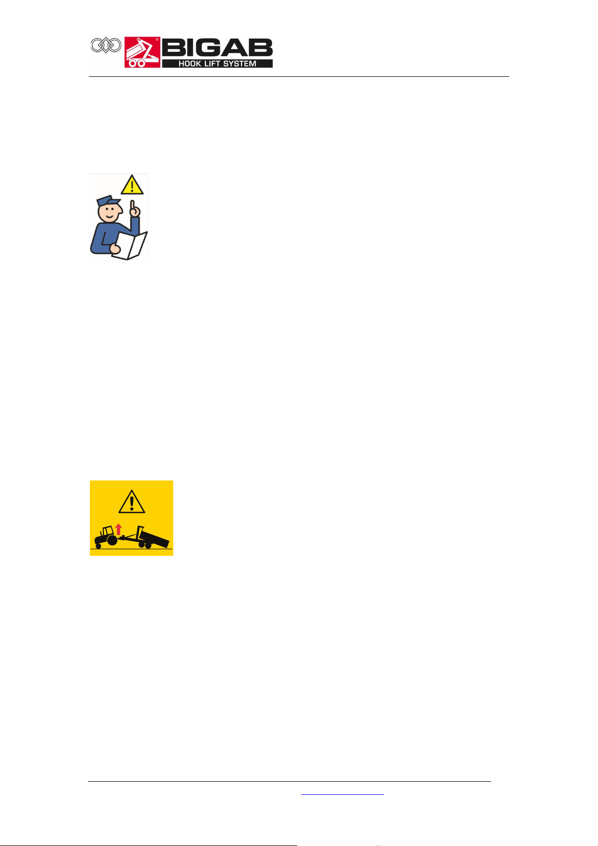
WARNING!
Warning - It is a hazardous movement if the rear end of the tractor lifts
Note! This warning label is included in the delivery of your trailer. It must be
attached in a conspicuous position in the tractor cab. If you would like more of these
labels, they are available to order, free of charge, from our after sales department.
Contact details are printed on the first page in the instruction manual.
WARNING!
22-27
It is absolutely forbidden to board the trailer when it is moving
Anyone doing so may be at risk of serious or fatal injury.
WARNING!
Risk of slipping
There is a risk of slipping as the surfaces of the trailer can be slippery due to a
combination of precipitation and oil and/or clay on the surface. The ground around
the trailer can also become slippery, as the tyres can tear up the surface and expose
clay and soil.
DANGER!
Hydraulic fluid under pressure
Hot hydraulic fluid at high pressure levels can occur in the hydraulic system. Take
care when connecting. Replace worn or damaged hoses.
© V7.1-2015W42-en Fors MW Ltd www.forsmw.com
17

INFORMATION!
Using the exchange unit
Do not operate the exchange unit unless the frame is folded down. During transport
with the trailer, the hook must be folded down in the parking position.
WARNING!
22-27
Use the safety support during all service operations
It is absolutely forbidden to lean under a raised frame unless it is secured with the
safety support. Under no circumstances may the trailer be carrying a load or
container when the safety support is being used.
WARNING!
Maximum load
It is absolutely prohibited to load more than the amount your model of trailer is
designed to handle. This can be dangerous for you and your surroundings.
© V7.1-2015W42-en Fors MW Ltd www.forsmw.com
18

WARNING!
Max. pressure on towing eyelet
Do not load so much that the pressure on the towing eyelet exceeds the permitted
laws and regulations. The trailer is designed for a maximum pressure of 3000 kg on
the towing eyelet. The pressure is largely determined by the way the load is
distributed on the container bridge, and it is the user’s responsibility to ensure that
this is not exceeded.
INFORMATION!
Tyre inspection
The tyres must be tightened and the brakes must be inspected regularly.
INFORMATION!
22-27
Lubrication
This decal is used to show the importance of regular lubrication of the trailer.
INFORMATION!
ID- plate
© V7.1-2015W42-en Fors MW Ltd www.forsmw.com
19

Marking of hydraulics
All of the hydraulic hoses are marked with coloured labels. See the table below for
more detailed information. The functions depend on the configuration of the
hydraulic system.
Hydraulic hose label (example tipping cylinder)
Hose label colors:
• Red - Oil from pump
• Blue - Oil to tank
• Yellow - Brake
Marking of the hydraulic hoses
.
No. Colour Function
1 Yellow Brakes
26 Red Steering (p)
27 Blue Steering (t)
22-27
© V7.1-2015W42-en Fors MW Ltd www.forsmw.com
20

22-27
7 COUPLING/UNCOUPLING THE TRAILER
Safety aspects when coupling/uncoupling
The following must be checked each time before use;
Inspect the trailer carefully.
Check the air pressure in the tyres. The tyres must always have at least the
recommended air pressure. See maintenance/service for more detailed information.
Check that all couplings are correctly connected.
Check that the trailer is locked to the towing vehicle.
Check the towing eyelet and the coupling device on the tractor.
Check the lights.
Check the brakes by testing them a few times without a load.
Check that hydraulic hoses and couplings are intact and not cracked.
Check that all hydraulic functions are working.
It is absolutely forbidden to use the trailer for any other purpose than as a hook lift
trailer.
Make absolutely sure that no unauthorized persons are in the working area of the
trailer.
Respect the safety distance. The hazard zone is 30 metres.
Never stand by the drawbar when coupling or uncoupling or when functions
between the towing vehicle and trailer are activated.
© V7.1-2015W42-en Fors MW Ltd www.forsmw.com
21

Do not exceed the maximum loading limit for the model of trailer. See Technical
Data for more detailed information.
Make sure that the trailer's SMV sign is in place and is clean.
Always examine the towing vehicle's parking system before loading. If necessary,
secure the wheels by placing chocks or obstacles in front of the wheels.
Study the safety regulations carefully.
WARNING! If the trailer is coupled behind another
trailer, the load capacity of the first trailer must be
reduced. The load capacity must be reduced by a load
equal at least to the second trailer's ball coupling
pressure on the first trailer.
22-27
COUPLING TO TRACTOR
When the tractor is connected and the drawbar is locked, always engage the
tractor’s parking brake before connecting hydraulic hoses and/or electrical cables.
Connect the trailer’s brake line to the tractor’s brake outlet.
Then connect the thick return line with the female coupling to the tractor’s free
return outlet. Free return is important to ensure optimal operation and
performance.
Connect the thick pressure hose with the male coupling to the tractor’s pressure
outlet.
Finally, connect both the lines that are to the steering axles to a double-action
hydraulic outlet with floating position.
Plug the 7-pole electrical connector into the tractor’s electrical outlet.
Connect the control unit to an electrical outlet rated at 16 amps or higher to obtain
sufficient power to the electromagnets on the manifold.
Connect the chain on the load transfer cylinder to the tractor’s top link bracket.
Adjust the chain so that when about 60% of the cylinder has been extended, the
chain is slack, and when the cylinder is retracted the chain is tensioned.
Disengage the parking brake NOTE! It is important that the parking brake is engaged
when the trailer is separated from the tractor.
© V7.1-2015W42-en Fors MW Ltd www.forsmw.com
22

22-27
8 DRIVING THE TRAILER
READ THE ENTIRE INSTRUCTION MANUAL BEFORE USING THE TRAILER.
CONSULT THE MANUAL IF YOU ENCOUNTER ANY PROBLEMS. THE TRAILER HAS A
MANUFACTURING PLATE. BEFORE USING THE TRAILER, MAKE SURE THAT THE
FACTORY SETTINGS HAVE NOT BEEN CHANGED AND THAT NO PARTS HAVE COME
LOOSE DURING TRANSIT. MAKE SURE THAT ALL SAFETY FEATURES AND SIGNS ARE IN
PLACE.
Safety aspects when driving
It is the responsibility of the user to ensure that a sufficiently powerful and heavy
towing vehicle is coupled to the trailer in all situations. The use of a towing vehicle
that is too small and insufficiently powerful can pose a risk of serious or fatal injury
for the user, be hazardous for the surrounding environment and cause damage to
the vehicle and trailer.
The load in the trailer must be evenly distributed. Loose items and loads that
protrude over the back or sides must be secured.
Remember that the weight of the trailer can adversely affect the tractor making it
more difficult to maneuver.
Do not forget to raise the stabilizer leg before moving off.
Never make tight turns at high speeds.
Do not exceed the maximum loading limit for the model of trailer.
Adapt your driving to the load, road conditions and your level of experience. The
trailer is designed for driving at a maximum speed of 40 km/h.
© V7.1-2015W42-en Fors MW Ltd www.forsmw.com
23

Maximum load is shown in
the Technical Data section.
Remember that with a long trailer bed and large overhang, the trailer needs more
room to maneuver and turn.
WARNING!
The trailer may only be driven in transport position. It
must never be driven with a raised bed. If you drive with a
raised bed, there is a risk of driving into bridges, electrical
power lines and other obstacles.
WARNING!
The manufacturer accepts no responsibility for damage that arises
as a result of overloading or, in the event of failure of the drawbar,
that arises if the trailer becomes detached from the vehicle.
22-27
It is absolutely forbidden to board the trailer
when it is moving. Anyone doing so may be at risk
of serious or fatal injury.
ROAD DRIVING INSTRUCTIONS
The steered axles are controlled by the tractor’s double-action outlet with
floating position. When driving forward, the lever is placed in floating mode so that
the trailer automatically follows the tractor. NOTE: Be very careful if a road has
sharp bends or is heavily cambered. Be extremely careful when roads are slippery.
When reversing the trailer, apply slight pressure in both directions using the doubleaction outlet. This will remove any accumulated air from the system.
Then watch the wheels and steer them in the intended direction.
Do not steer at too sharp an angle as this can make it difficult for the tractor to
follow the trailer.
© V7.1-2015W42-en Fors MW Ltd www.forsmw.com
24

NOTE: Reset to floating mode before driving the trailer forward.
When steering with steerable axles with a double – active valve with float
position from tractor which is standard on 22 – 27, it is imperative to stand still with
the trailer when you switch between blocking force controlled axles and floating
position on the axles.
When driving on normal road the axles should always be unlocked, by having the
tractor lever in the float position. It is absolutely forbidden to change the statues of
the axles from floating to the locked position when driving. If you lock or unlock
them while driving, there may be tension and pressure on the axles that make them
stand in improper angels, and then you can lose control of the trailer.
When you start to roll after putting the axles into floating position, caution should be
taken since the axles need to align themselves in the direction after being locked in a
different angle. This must be done at low speed. Even at sharp turns and bumpy
roads the speed needs to be adapted so that the trailer follows the tractor.
Remember that in cold weather, the oil is thick and that it then takes longer time for
the axles to come in the right position.
Axles locked = Axles standing still and straight after the trailer. To be used when
reversing and when you hook on the bridge this so that the trailer rolls underneath
the container when hooking.
Axles unlocked = Axles move freely and follow the trailer. The tractor lever is in the
float position. Note! The conversation to unlocked axles may only be done when
standing still.
Forced axles with double – active jack should only be used when reversing and when
you need to control the trailer to a given direction at very low speed.
22-27
Load on towing eyelet and coupling
Always adapt your driving to the load, road conditions and your level of experience.
Do not exceed the maximum speed specified for the trailer. Make sure that you have
the correct pressure on the tow hook when you are driving. Do not exceed the
intended upward and downward pressures on the trailer’s towing eyelet and the
coupling to the hitch. The given ideal conditions and theoretical calculations indicate
the following maximum load values, and it is recommended that the user observes
these load values.
© V7.1-2015W42-en Fors MW Ltd www.forsmw.com
25

22-27
The above table provides information and examples of how many different loads can
weigh. This table should only be used as a general guide. The manufacturer cannot
be held responsible for measurements or volumes stated in the table. The
information in the table is intended only as a recommendation.
WARNING!
An incorrectly distributed load can adversely affect
the steering of the tractor and trailer making them
difficult to maneuver.
Working under extreme conditions
The recommended working temperature for a BIGAB dump trailer is –20°C to +40°C.
When working in temperatures below the recommended temperature, the trailer
should not be loaded as heavily. When working in low temperatures, always allow
the oil to circulate freely through the system for a few minutes before starting work.
In very hot conditions, you should be aware that the hydraulic oil heats up
drastically. At temperatures above +80°C, the oil evaporates and the seals in the
system will be damaged.
© V7.1-2015W42-en Fors MW Ltd www.forsmw.com
26

IF A DANGEROUS SITUATION ARISES
If the trailer comes into contact with high voltage electric wires, you should do the
following:
IF YOU ARE OUTSIDE THE TRAILER
Do not attempt to get into or close to the trailer. Keep everybody well away from the
trailer. Do not touch any part of the trailer.
IF YOU ARE INSIDE THE TOWING VEHICLE
Get out of the vehicle by jumping. Avoid touching any part of the vehicle. Avoid
making your body into a channel through which the electricity can flow. Get out of
the vehicle by jumping but make sure that your feet do not touch the ground at the
same time. An electric field at ground level can cause fatal voltage between the legs.
You should be safe at a distance of about 20 meters from the vehicle, but this
naturally depends on circumstances such as the voltage in the overhead power lines,
ground conditions, etc.
22-27
EXCHANGE MECHANISM
The illustrations below show a hydraulic frame lock which controls the handling of
the exchange mechanism and the hydraulic container lock. The exchange mechanism
is located in the middle of the rear frame.
Tipping position
Hook frame
Locking pin
Rear frame
Hydraulic cylinder
Exchange mode
© V7.1-2015W42-en Fors MW Ltd www.forsmw.com
27
22-27
9 EXCHANGE OPERATION
Safety aspects during exchange operation
The hook lift trailer must only be operated by one person in order to avoid injury
when working with the trailer. There should be no one inside the hazard zone, which
is 25 meters around the trailer.
Unauthorized persons must keep well away from the trailer when it is being used or
repaired. It is strictly forbidden for anyone under the influence of alcohol or drugs to
work with the trailer.
Exchange and tipping must be operated from the towing vehicle!
Make sure that the frame lock is activated. Make sure that the hook is properly
locked on to the container eyelet.
WARNING!
It is hazardous if the rear end of the tractor lifts
Do not, under any circumstances, reverse the towing vehicle or use it to push the
trailer when exchanging. This poses an immediate risk of damaging the trailer or
towing vehicle and can lead to serious or fatal injury.
© V7.1-2015W42-en Fors MW Ltd www.forsmw.com
28

aligned straight in front of
Failure to read this instruction manual may lead to serious or
Exchange procedure
The trailer must be
Fig. 1
Fig. 2
22-27
Make sure that the hydraulic
mode switch for exchanging or
tipping is in exchange mode
and not in tipping mode. Make
sure that the container lock is
in its open position.
Park the hook lift trailer on a flat surface. It must not be
leaning sideways by an angle of more than 5 degrees.
fatal injury.
Do not, under any circumstances, reverse the towing vehicle or use it to push the trailer
when exchanging. This poses an immediate risk of damaging the trailer or towing vehicle
and can lead to serious or fatal injury. The load must be pulled on and the trailer and
towing vehicle must roll in under the freely suspended load.
© V7.1-2015W42-en Fors MW Ltd www.forsmw.com
29

ground!
you have passed the rollers, always keep the hook lift trailer’s frame close
Fig. 3
Roll-on!
Make sure that the load carrier is inside the steering rollers. Release the
The tower must be fully retracted when rolling on the container bridge in
STOP
Stop if the tractor lifts off the
Make sure that the hook
hitches around the loop.
Make sure that the frame lock is activated.
brakes on both the towing vehicle and the trailer to make it easier to roll on
the load. Check the position of the tower during roll-on so that the container
bridge frame does not catch on the rollers from behind.
order to increase the lifting power and reduce the strain on the towing
eyelet. Ensure that the container frame does not catch in the rollers at the
back of the trailer. Adjust the tower upwards continually during exchange in
order to move past the rollers. If the tower is not adjusted upwards during
roll-on, there is a considerable risk of the exchange’s lock being damaged if
the container frame catches in the rollers.
IMPORTANT! Follow the movement with the retractable tower so that the
front of the hook lift trailer’s frame does not catch on the rollers. When
22-27
© V7.1-2015W42-en Fors MW Ltd www.forsmw.com
30
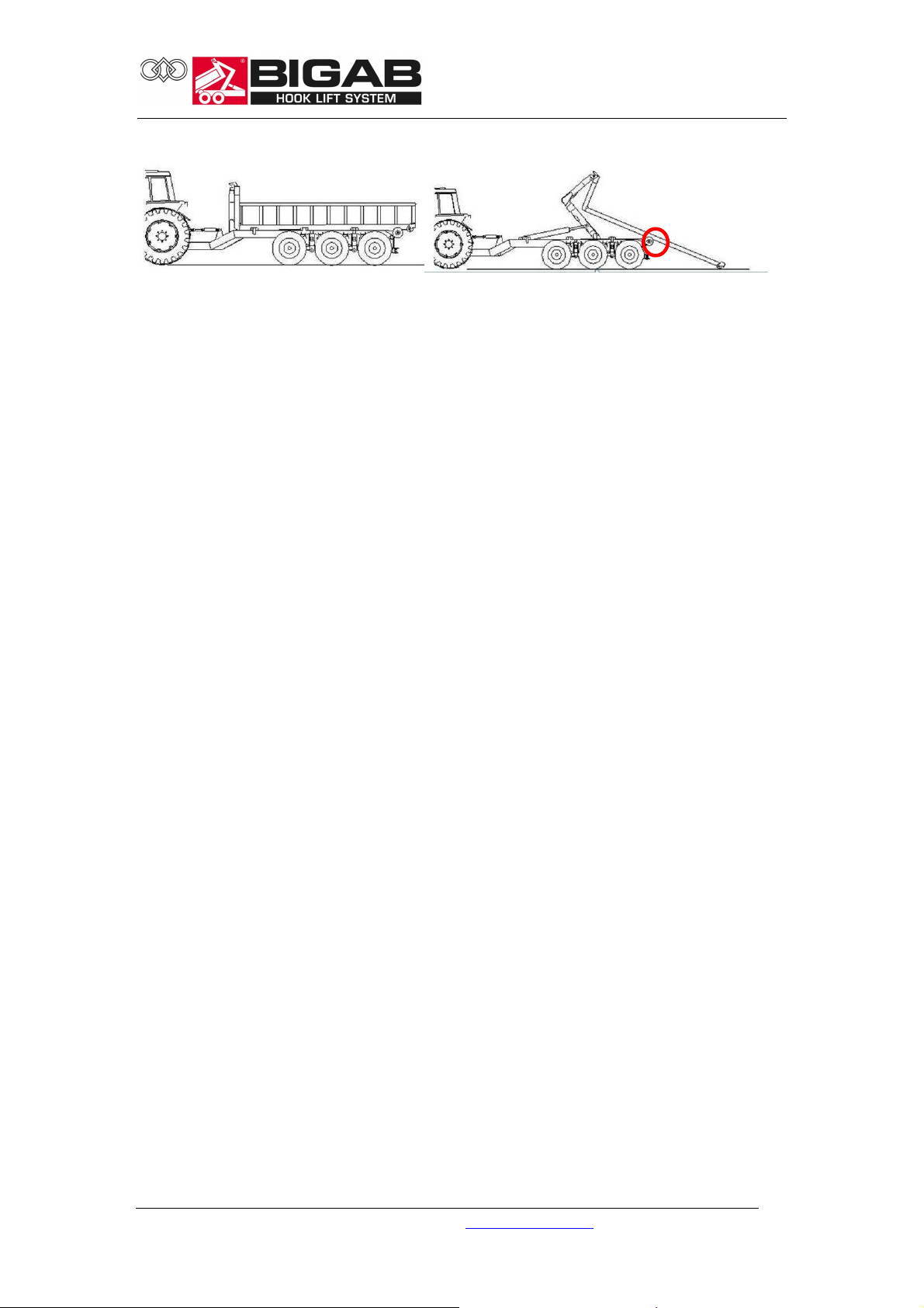
Fig. 4
22-27
Roll-off!
Release the brakes on both the towing vehicle and the trailer to make it easier to roll off the load. Check
the position of the tower during roll-off so that the container bridge frame does not catch on the rollers
from above.
Lock the frame and activate bogie blocking between the towing vehicle and trailer.
being damaged if the container frame catches in the rollers.
1. Raise the hook lift frame slightly so that the container bridge does not scrape against the frame
when it is pushed backwards.
2. Then retract the tower so that the locking rails/wings on the container bridge frame move freely and
cannot be damaged.
3. Adjust the tower upwards continually so that the container frame does not catch on the rollers at
the back of the trailer during roll-off.
4. If the tower is not adjusted during roll-off, there is a considerable risk of the exchange’s lock
© V7.1-2015W42-en Fors MW Ltd www.forsmw.com
31

22-27
10 TIPPING OPERATION
Note! The maximum container bridge length for models in this instruction manual is
6.5 metres during tipping. Make sure that the towing vehicle and trailer are securely
coupled before tipping.
Fig. 5
Fig. 6
Park the hook lift trailer on as flat a surface as possible. It must not be leaning
sideways by an angle of more than 5 degrees.
Note! With maximum load, the
telescope must be retracted 40 cm
(400 mm) to enable tipping.
Make sure that the frame lock is
in the correct position.
At maximum tipping, drive slowly forwards until the container bridge is empty.
Lower the bridge before driving off. Important! Make sure that the bridge is
locked in the correct position before driving off.
Fig. 7
IMPORTANT!
Apply the brakes when tipping so
that the tractor and trailer do not roll
away when the load is being
emptied.
Make sure that the frame lock is
activated before tipping.
© V7.1-2015W42-en Fors MW Ltd www.forsmw.com
32

11 WIRING DIAGRAM
The trailer has a 12 volt electrical system.
Wiring diagram tail lights
22-27
© V7.1-2015W42-en Fors MW Ltd www.forsmw.com
33

No. Item number
Name
Quantity
1 920695
7-
pole junction box (male)
1
2 920764R
Tail lights BIGAB 3 pole, right
-
hand side
1
3 920764L
Tail lights BIGAB 3 pole, left
-
hand side
1
4 920764G
Glass cover tail
light 2
5 920745
Bulb 12V, 21W
2
6 920768
Bulb 12V, 21W p21/5W
2
22-27
© V7.1-2015W42-en Fors MW Ltd www.forsmw.com
34
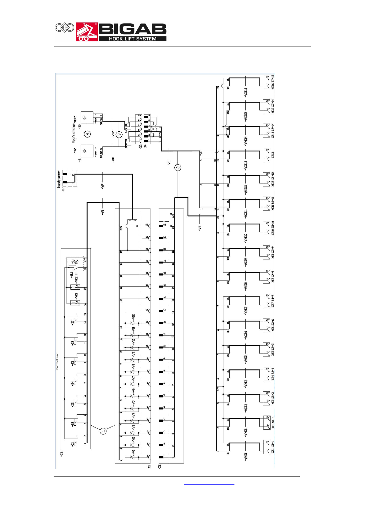
Electrical on-off system
22-27
© V7.1-2015W42-en Fors MW Ltd www.forsmw.com
35

Pos. Item No.
Name
1 913261L
Tipping/exchange cylinder
1 913262R
Tipping/exchange cylinder
2 913245
Telescopic cylinder with
pilot operated valve
3 913230
Exchange cylinder
4 313116
Cylinder container lock
5 313134
Cylinder frame lock
6 313140
Cylinder suspended drawbar
7 913235
Start cylinder
8 913630
Pilot operated check valve
9 913640
End of stroke valve
22-27
12 HYDRAULICS CHART
The hydraulic system is filled with oil and tested before delivery. The hydraulic
system consists of a number of different components illustrated below. Technical
data and configuration depend on the trailer model (see table 1). The hydraulic
system is filled with either VMGZ or SAE100R16 hydraulic oil. It is applied as a
working fluid for the hydraulic system for continuous operation outdoors at
temperatures from -50°C up to +60°C.
Spare parts list Hydraulic components
© V7.1-2015W42-en Fors MW Ltd www.forsmw.com
36

13 CARRYING OUT SERVICE/MAINTENANCE
22-27
Place the jack as illustrated when carrying out service and maintenance work, if a
jack is required.
To ensure the safe use of the product and trouble-free operation and for the
warranty to be valid, maintenance must be carried out as described in this chapter.
Clean the trailer thoroughly before carrying out repair work or storage.
The trailer must be standing on a flat surface during maintenance and service work.
Make sure that the trailer cannot move.
When servicing the trailer, turn off the vehicle engine.
© V7.1-2015W42-en Fors MW Ltd www.forsmw.com
37

Make sure that the trailer cannot move when using a jack or similar equipment - it is
essential that the trailer is supported securely when raised.
Always use the safety support when carrying out service work when the trailer bed is
raised. There must be no load or container bridge on the trailer when carrying out
service work on the trailer in raised position. See illustration below.
Never attempt to carry out any maintenance work on the hydraulic system until you
are absolutely certain that there is no hydraulic pressure.
Do not attempt to seal or repair leaking hydraulic couplings while the system is still
pressurized.
Never attempt to locate a leakage from hoses or couplings with your hands. The
high-pressure oil in the system can penetrate the skin and cause serious injuries,
such as burns and blood poisoning. High pressure oil is highly flammable.
Avoid getting oil in your eyes. Wear safety goggles and safety gloves. If you do get oil
in your eyes, flush them immediately with cold water and seek medical help at once.
22-27
Raised bed
It is absolutely forbidden
to lean under a raised
frame unless it is secured.
WARNING!
The trailer may only be driven in transport position. It must
never be driven with a raised bed. If you drive with a raised
bed, there is a risk of driving into bridges, electrical power
lines and other obstacles.
© V7.1-2015W42-en Fors MW Ltd www.forsmw.com
38

22-27
14 MAINTENANCE/SERVICE
General information:
• Service and maintenance must be carried out regularly in order to guarantee
your safety and problem-free use.
• Maintenance work can be carried out without any specialist tools. Most of
the maintenance operations can be performed by the user.
• Locate the problem as well as you can to avoid having to open the system,
unless this is absolutely necessary.
• Any parts that are dismantled must not come into contact with dirt.
• Keep spare parts in their packaging until they are required.
• We recommend that adjustment and repair of valves is carried out by trained
service personnel.
Daily maintenance:
• Visually inspect the load equipment. Note any defects that might affect your
safety. Repair any defects. Carefully inspect the towing eyelet.
• Check the hydraulic system for leaks and hoses for damage.
• Inspect each feature carefully.
• Check oil level.
Weekly maintenance:
• Regularly wash the trailer with a sponge or soft brush and mild soap solution.
Never wash the trailer with hot water and high pressure. This dissolves the
grease at the bearing points.
• Inspect the operation of the trailer.
• Check the hydraulic pressure.
• Check that the brakes are working properly.
• Tighten all wheel nuts after a few hours and check them regularly. Refer to
the list of tightening torques in the chapter on safety devices.
• Check the direction indicators, lamp glass covers, reflectors and lighting.
Monthly maintenance:
• Check the air pressure in all tyres.
• Make sure there is sufficient lubrication on the sliding surfaces.
• Clean the hydraulic cylinders and lubricate their bearings.
• Inspect the hydraulic hoses for damage.
For recommended lubricating greases, see Requirements and test methods SS 15 54
70
http://www.sp.se/km/grease
© V7.1-2015W42-en Fors MW Ltd www.forsmw.com
39

Surface cleaning
Remove accumulated dirt and dust. Painted external surfaces should be cleaned
regularly with a sponge or soft brush and soap. When cleaning, never use warm
water in a high-pressure washer. This dissolves the grease at the bearing points.
Maintenance of the hydraulic units
See the hydraulics chart chapter for information about the hydraulic system.
• Clean the hydraulic cylinder piston rod.
• Inspect the hydraulic valves. If a leak is detected, replace the damaged valve.
• Inspect the hydraulic hoses:
• Visually inspect the hydraulic hoses and coupling pipe. If a leak or rupture is
detected, replace the hose.
• Check the oil level. If necessary, top up with oil or change the oil.
• Check the operation of the device.
Always use original parts when replacing hydraulic components such as hoses, seals,
etc. This ensures safe and reliable operation. Be sure to remove all dirt before
starting any work on hydraulic components.
Note! Never operate the hydraulic system if the oil level falls below the lowest
mark.
Changing seals
Replacement of seals should be carried out by an authorised workshop.
Maintenance of the pneumatic units (optional equipment)
• Clean and lubricate the piston rods on the pneumatic cylinders.
• Empty the water trap:
• Condensed water must be removed from the air tank located at the side of
the trailer.
• Check the pneumatic valves:
• Check the pneumatic valves by listening to them when they are working. If a
leak is detected, replace the damaged valve.
• Check the pneumatic hoses:
• Visually inspect the pneumatic hoses and coupling pipe. If a leak or rupture is
detected, replace the hose.
• Check the operation of the device.
22-27
© V7.1-2015W42-en Fors MW Ltd www.forsmw.com
40

Maintenance of the brake system
This trailer has a hydraulic brake system. Air brake system with negative or positive
action is optional.
The brake system must be inspected regularly. Test the brakes at least once a week
when the trailer is being used.
Make sure that no grease, lubricant or oil enters the brakes. If any type of oil enters
the brakes, there is a risk of it lubricating the brake discs and thereby reducing the
friction. This adversely affects brake performance.
Should this happen, remove the brake drums and change the brake discs.
Always check the play after removing the brake drum and adjust if necessary.
To adjust the brakes, lift the bogie frame off the ground and adjust the brakes by
spinning the wheel while adjusting. The brakes are correctly adjusted when the
wheel spins freely without any scraping noises. The brakes must always be tested
after adjustment.
If brake performance is uneven, apply the brakes, tow the trailer slowly for a couple
of hundred meters, then test the brakes again by braking the tractor and trailer at
normal speed. Repeat if necessary until the brakes work properly. If necessary,
contact our service department!
With the BIGAB 22-27, brake cylinder play is adjusted by slackening or tightening the
adjustment screw on the brake.
Maintenance of wheels
Before the trailer is used, check the wheels by making sure the bolt connections are
secure and that they are regularly checked and tightened.
• Inspect the bolt connections.
• Check the air pressure.
For information about wheels, see the table in the chapter on main components.
For information about tightening torques, see the chapter on safety devices.
22-27
© V7.1-2015W42-en Fors MW Ltd www.forsmw.com
41

Maintenance of the hook lift trailer’s bogie system
Daily inspections
Inspect all spring brackets, springs with links and wheel axles.
Inspect wheel equipment, tires and rims.
Defects must be corrected before the trailer is used.
Weekly inspections
It is essential to lubricate the trailer’s grease nipples once a week, or after 20 hours
of use. Refer to the lubrication schedule. You need to get under the trailer for best
results when lubricating the grease nipples. This is easiest if the trailer is unloaded.
Changing tyres
When changing tyres, the jack must be placed as illustrated below.
22-27
© V7.1-2015W42-en Fors MW Ltd www.forsmw.com
42

Storage
Long term storage in cold and/or damp conditions is not advisable.
Repair welding
If repairs or modifications require welding work, first contact your dealer for
necessary instructions. Incorrect welding or lack of knowledge when welding can
result in sudden breaks in the structure.
Recycling
All metal parts can be recycled and must be taken to a recycling facility at the end of
the trailer's useful life.
Scrapping instructions
If the machine or its components are to be scrapped, the materials must be
dismantled, sorted and handed in for recycling or destruction at a location
designated for this purpose by the municipality.
22-27
© V7.1-2015W42-en Fors MW Ltd www.forsmw.com
43
foldable tower
Right; & Left
Right;&Left x1
Left&Right
Container lock
right x1
Lubrication
Recommended lubrication is once a week or every 20 hours of operation. A grease
gun is recommended for lubrication of grease nipples.
• Follow the lubrication schedule to ensure correct and regular lubrication of
your trailer.
• Keep flammable material away from heat, sparks and naked flames.
• Do not let oil run out onto the ground. Oil pollutes the environment.
Link bearing, left; x1
Apply grease to slide
bearings on the
Brake key
Brake arm
Steering spindle x2
Position end stop
Left & Right
Brake arm
Brake key
Brake key
Brake arm
Steering spindle
x2
Position end stop
Bearing steering rollers, left,
22-27
Towing eyelet
Cyl. link bearing x2
Glide bearing x1
Link bearing, right; x1
Glide bearing
Exchange
lock/Tipping/Exchange
Spherical bearing
Exchange frame
bearing, x1
Bearing load-bearing axle,
left, right, x1
© V7.1-2015W42-en Fors MW Ltd www.forsmw.com
44
+0
+0
+0
Tightening torque
• Tightening torque - Drawbar bolts
Thread Bolt
strenght
M16x2 12.9 333
M20x2 12.9 649
• Tightening torque - Wheel nuts
Tightening
torque, Nm
22-27
Thread Nut strenght Tightening
torque, Nm
M18x1,5 10 270 +20
M20x1,5 10 350 +30
M22x1,5 10 450 +60
© V7.1-2015W42-en Fors MW Ltd www.forsmw.com
45

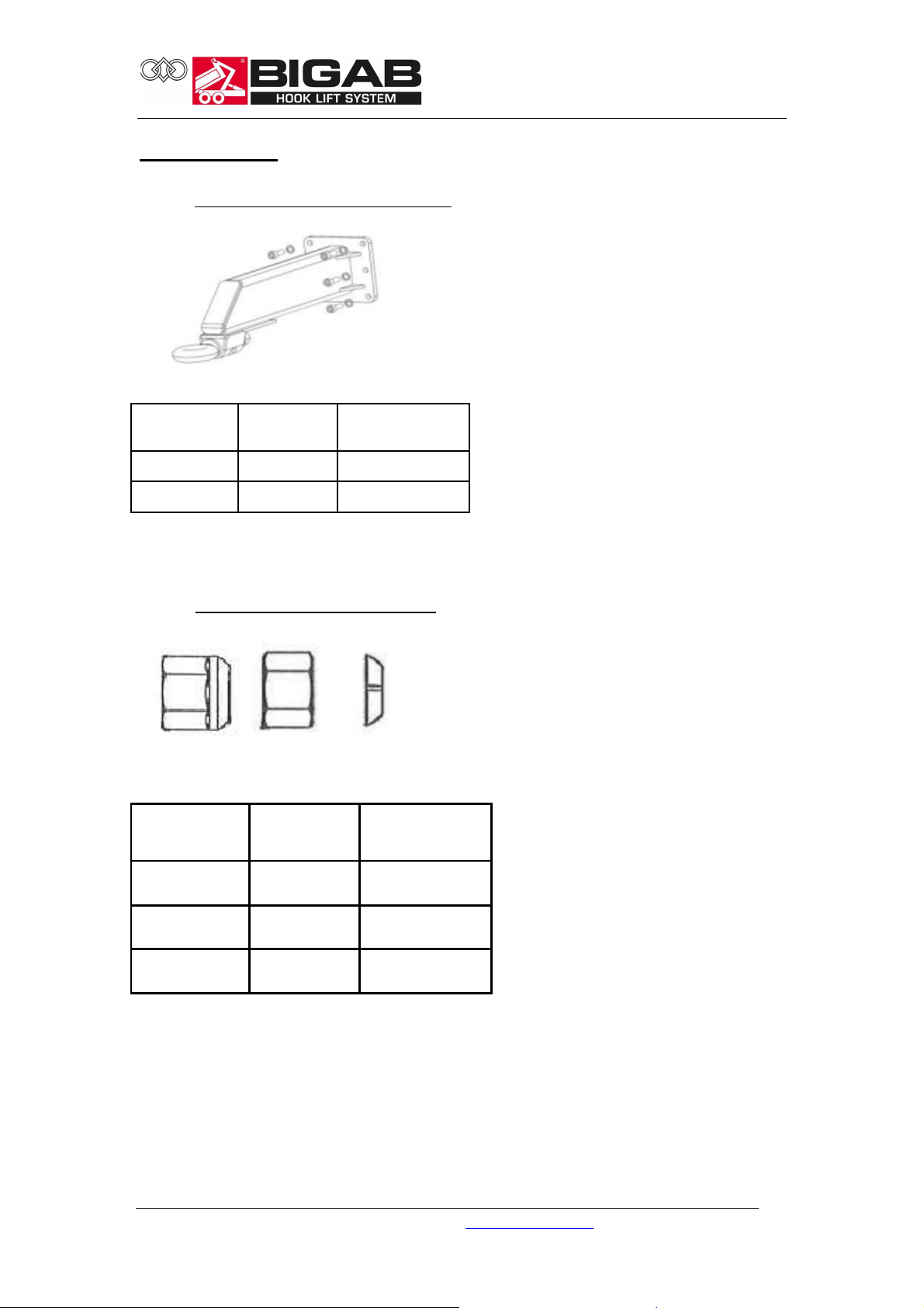
Pos. Item No.
Name
Hook frame assembly
1 37221269
Telescopic linkage frame
2 37221079
Hook frame/extension
3 37221112
Axle
4 37221110
Axle
5 37221115
Axle
6 37211180
Distance rin
g
7 37203115
Distance ring
8 909125
Glide bearing
9 37221140
Direction plate
15 SPARE PARTS
Hook frame
22-27
Hook frame spare parts
4
© V7.1-2015W42-en Fors MW Ltd www.forsmw.com
46

Pos. Item No.
Name
1 37221500
Frame
2 372320370
Axle
3 320350
Steering roller
4 909115
Slide beari
ng Ǿ100
Rear frame
Rear frame spare parts
4
2
22-27
© V7.1-2015W42-en Fors MW Ltd www.forsmw.com
47

Pos. Item No.
Description
Mechanical
Pneumatic
1 917220
Sprung Tridem Parabolic 30 tonnes
* *
2 917171
Fixed axle 130x2000
*
2 917181
-PN
Fixed axle 130x2100
*
3 917172
Self-steering
axle 130x2000
*
3 917182
-PN
Self-steering axle 130x2100
*
4 913231
Hydr. cyl. 80/50x249 Steering
* *
4 FMWA20009
-01
Steering cylinder assembly kit
* *
5 920845
Air brake cylinder 20" M16
*
6 917160
-
SP1 Brake cylinder 30/37 Fixed axle
*
7 917160
-SP2 Brake cylinder 25/30 Steering axle
*
8 916498ADR
Brake shoe set 406x120
* *
9 916480
Wheel nut M22x1.5
* *
Bogie
1
22-27
Bogie spare parts
9
4
8
5.7 5.7 5.7
4
3 2 3
© V7.1-2015W42-en Fors MW Ltd www.forsmw.com
48

Pos. Item No.
Description
3 2024
-
000011.000
Linkage frame cylinder
4 2024
-
000027.000
Link frame lock chain
- tractor 15
-19-22-27
5 2024
-
000013.000
Link cylinder frame lock chain
12 2024
-
000015.000
Pin
14 2024
-
000010.001
-01
Pin
17 FMWP00001
-
030 Pin
22 908110
Split pin
24 920230
Ring pin
26 920222
Chain for frame lock
32 313135
Hydraul
ic cylinder
33 908640
Spring washer
34 907255
Nut
35 908275
Flat washer
36 FMWP00083
Ring
37 FMWP00083
-01
Ring
Frame lock
221732221714242414 37 3 36
22-27
12
33
34
35
26
Frame lock spare parts
5
© V7.1-2015W42-en Fors MW Ltd www.forsmw.com
49

Pos. Item No.
Name
Note:
Exchange unit assembly
1 37221120
Pin
2 920515
Spring
3 37221220
Sliding plate
4 37221210
Sealing ring
5 913230
Exchange cylinder
Exchange unit
3
5
22-27
Rear frame
1, 2, 4
Exchange unit spare parts
© V7.1-2015W42-en Fors MW Ltd www.forsmw.com
50

Pos. Ite
m No.
Description
1 920764R
Rear lamp Right
1 920764L
Rear lamp Left
2 920770
Side marker lights 111x40 (orange)
- optional
3 920715
Cable terminal
4 920695
Cable connector 7 pole (male)
5 920180
Cable connector 7 pole (female) special
6
920768
Bul
b 12V 21W p21/5W
7
920745
Bulb 12V, 21W
22-27
Electrical system
For information about the electrical system, see the wiring diagram chapter.
1
Electrical spare parts
© V7.1-2015W42-en Fors MW Ltd www.forsmw.com
51

Pos. Item No.
Description
Note
1 930105
Lubricating nipple
2 920120
Towing eyelet
3 37221002
Hook
4 37211068
Stabiliser leg
5 37203067
6 37203085
Safety support
7 920160
Reflector 94*44 (orange)
8 920150
SMV sign
9 920630
Parking chock
Optional
10 920631
Parking chock holder
Optional
Other parts
22-27
Other spare parts
Stabiliser leg pin
© V7.1-2015W42-en Fors MW Ltd www.forsmw.com
52
22-27
16 TROUBLESHOOTING
These troubleshooting instructions are intended to help you determine the cause of
a malfunction.
Problems with the electrical equipment
Fault symptoms Reason and action
Problem with lights Bulb not working. Replace the bulb.
Check and clean the electrical
connectors.
Wire damaged or broken. Check and repair the wire.
Problems with the hydraulic equipment
Fault symptoms Reason and action
Too slow movement or the cylinder
does not return from extended position
to neutral.
Air in the hydraulic system Locate the leak and eliminate the fault.
Low oil pressure. Adjust the oil level.
Hydraulic cylinder piston seal leaking. Replace the gasket.
Noise coming from the hydraulic
system.
Oil leak Replace ruptured hose. Adjust the hose
Problem with brake system
The valve has stuck. Clean the valve
parts. The valve should be able to move
freely.
Check the oil level. Check the quick
release couplings between the tractor
and trailer
Air has entered the system. Locate
where the air is entering and eliminate
the fault.
connections
Fault symptoms Reason and action
Poor brake operation.
Oil on brake linings or worn brake pads.
Check the play in the brake arm and
© V7.1-2015W42-en Fors MW Ltd www.forsmw.com
Replace the brake shoes
adjust if necessary.
53

17 EC DECLARATION (sample)
22-27
© V7.1-2015W42-en Fors MW Ltd www.forsmw.com
54
 Loading...