

Page 1
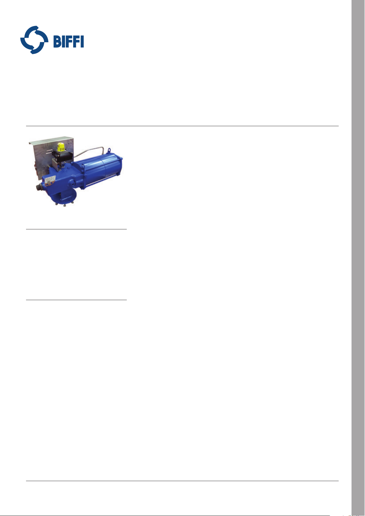
RPS SPRING RETURN PNEUMATIC ACTUATOR
INSTALLATION, OPERATION AND MAINTENANCE MANUAL
Before installation these instructions must be fully read and understood
1.1.1 Applicable regulation
EN ISO 12100-1: 2005: Safety of machinery Basic notions, general design principles.
Part 1 - Basic terminology, method.
EN ISO 12100-2: 2005: Safety of machinery Basic notions, general design principles.
Part 2 - Technical principles and specification.
2006/42/EC: Machine directive.
97/23/EC: Directive for pressure equipment
(PED).
2006/95/EC: Directive for low voltage
equipment.
2004/108/EC: Directive for the electromagnetic
TABLE OF CONTENTS
1. General warnings .......................................... 1
2. Installation ..................................................... 4
3. Operation and use ......................................... 8
4. Operational tests and inspections.............. 11
5. Maintenance. ............................................... 11
6. Troubleshooting .......................................... 16
7. Layouts ......................................................... 16
8. Date report for maintenance operations ... 21
1 GENERAL WARNINGS
IMPORTANT
The manual is an integral part of the machine.It
should be read carefully before carrying out any
operation and should be kept for future reference.
1.1 Generalities
Biffi actuators are conceived, manufactured
and controlled according to the Quality Control
System in compliance with EN ISO 9001
international regulation.
94/9/EC: Directive and safety instructions
1.1.2 Terms and conditions
Biffi guarantees that all the items produced
are free of defects in workmanship and
manufacturing materials and meet relevant
current specifications, provided they are
installed, used and serviced according to the
instructions contained in the present manual.
The warranty can last either one year from
the date of installation by the initial user of the
product, or eighteen months from the date
of shipment to the initial user, depending on
which event occurs first. All detailed warranty
conditions are specified in the documentation
forwarded together with the product. This
warranty does not cover special products or
components not warranted by subcontractors,
or materials that were used or installed
improperly or were modified or repaired by
unauthorized staff. In the event that a fault
condition be caused by improper installation,
maintenance or use, or by irregular working
conditions, the repairs will be charged
according to applicable fees.
compatibility.
for use in hazardous area.
Emerson.com/FinalControl © 2017 Emerson. All rights reserved.
VCIOM-03749-EN 17/12
Page 2
RPS SPRING RETURN PNEUMATIC ACTUATOR
INSTALLATION, OPERATION AND MAINTENANCE MANUAL
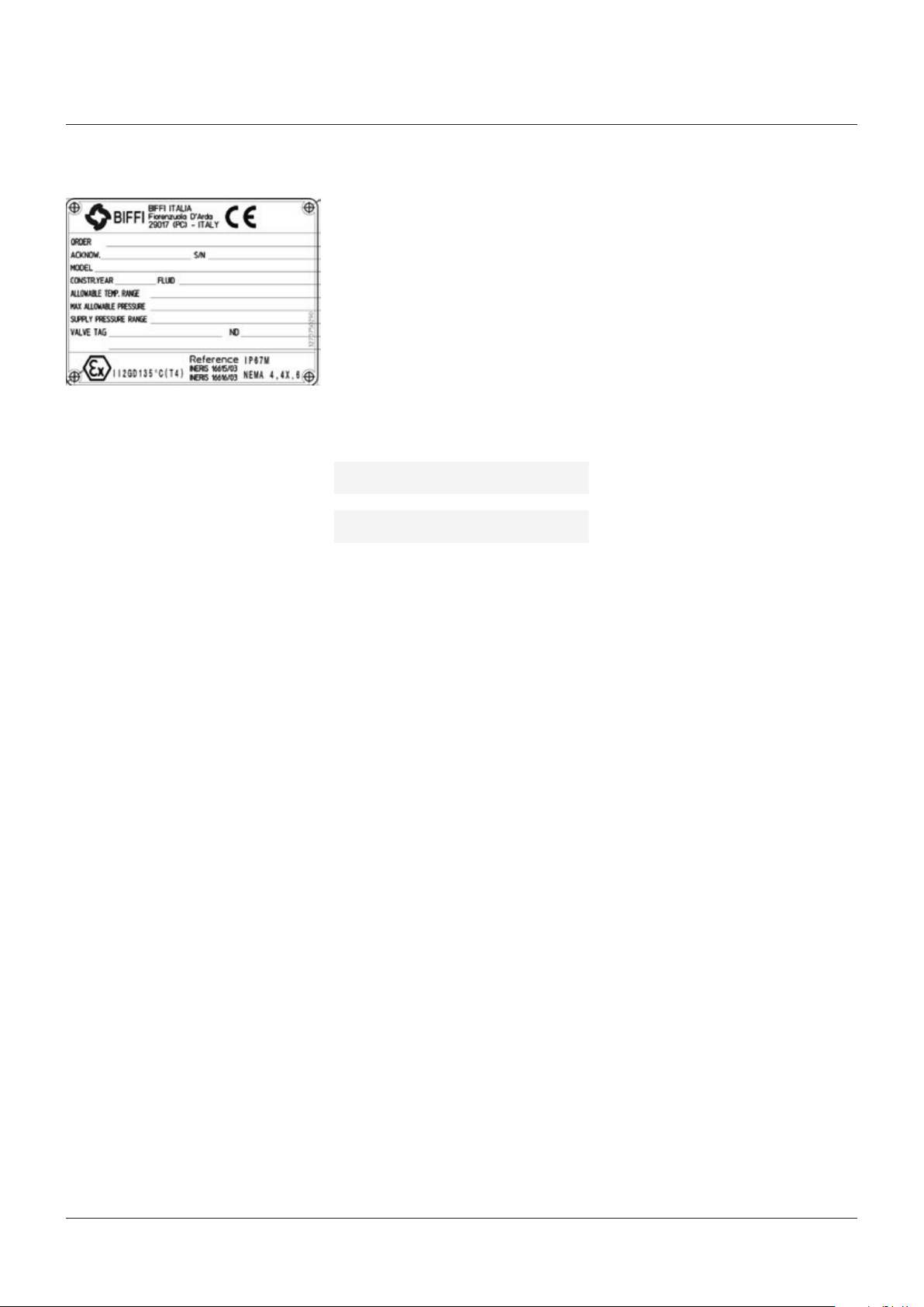
FIGURE 1
Data plate
1.2 Identification plate
It is forbidden to modify the information and the
marks without previous written authorization
by Biffi.
The plate fastened on the actuator contains the
following information (figure 1).
1.3 Introducing the actuator
RPS actuators are pneumatic low-pressure
spring return, suitable for any quarter turn
application such as ball, plug, butterfly valves
or dampers, in both ON-OFF and modulating
heavy-duty service.
The actuator is made up of a rack and pinion
mechanism, which transforms the linear
movement of the pneumatic cylinder, in one
direction, and of the spring, in the opposite
direction, into the rotary movement for the
valve operation. An adjustable bronze sliding
block supports the transverse force exerted on
the rack by its engagement with the pinion. The
rack is nitride for ensure the minimal friction.
The spring module incorporates one or two
springs in series, depending on the model,
and is fully encapsulated. This assures safety
to personnel and ease of assembly. External
travel stops allow precise angular stroke
adjustment between 80° and 100°.
Totally enclosed, weatherproof housing, made
of nodular cast iron for maximum strength and
suitable for use in hostile environments.
The mounting flange is identical on both
(upperand lower) faces of the housing; the
shaft output drives have the same dimensions
but is positioned at 90°. This allows the
actuator to be used as spring to close or spring
to open without modification.
The actuator is assembled onto the valve by
connecting the actuator housing flange to the
valve flange by a spool piece and the actuator
shaft to the valve stem by a stem extension.
Actuator manual emergency operation in
opposition to the spring action, is performed
by rotating the jackscrew by a wrench or by a
handwheel (available on request).
The mounting flange, on the housing top, can
be utilized for the assembly of limit switches,
position transmitter, positioner etc., which are
actuated by the actuator output shaft.
The actuator housing is provided, on the front
face and in the back face (optional), with
threaded holes for the assembly of accessories
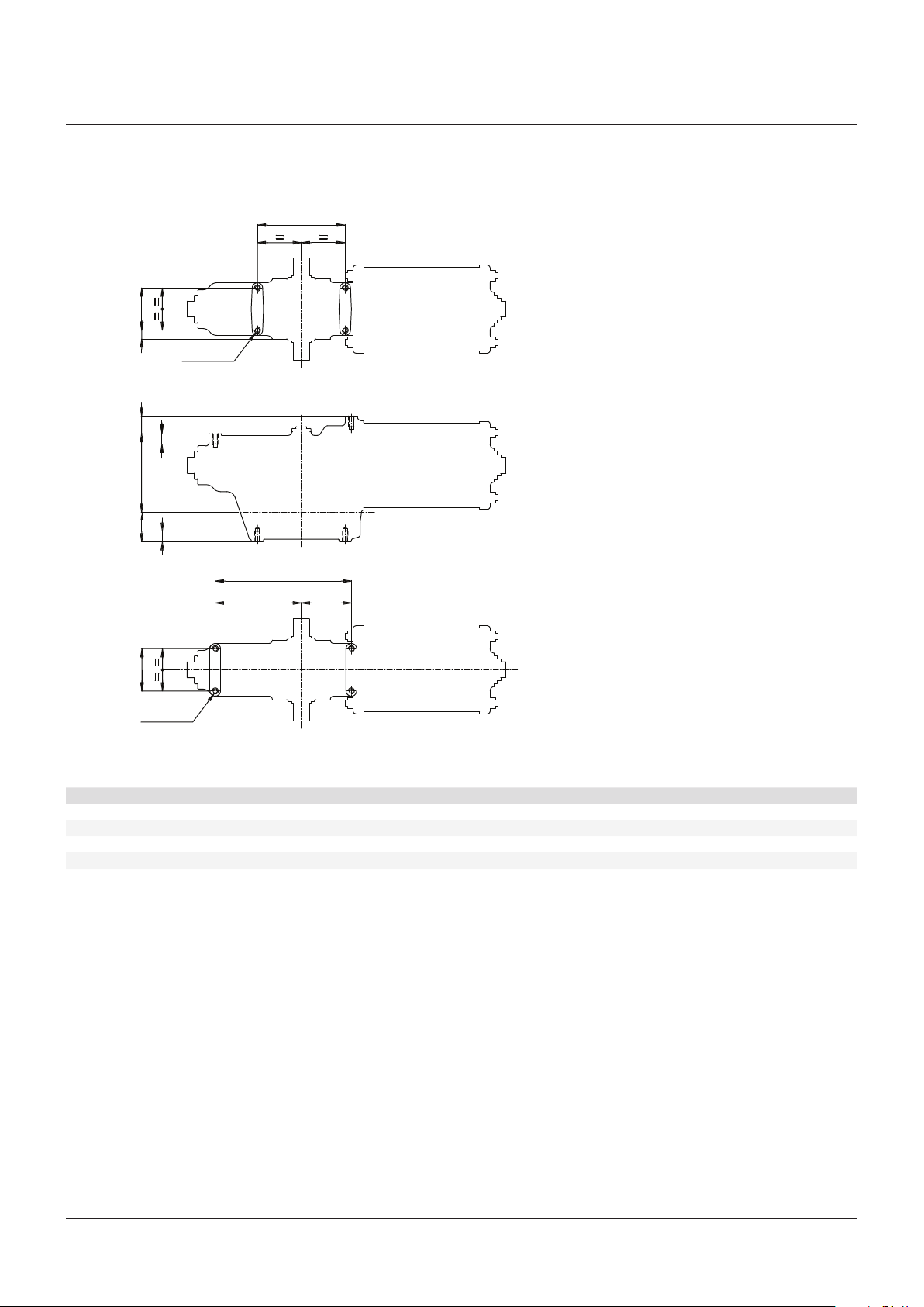
(control panels, air storage tank, etc.).
The expected lifetime of actuator is
approximately 30 years.
1.4 Technical data
Supply fluid Air, nitrogen or sweet gas
Operating
temperature
Design pressure 12 bar maximum
Supply pressure Please refer to technical data
Output torque Up to 3700 Nm
Standard: from -30°C to +100°C
Optional: from -60° to +140°C
sheet
2
Page 3
RPS SPRING RETURN PNEUMATIC ACTUATOR
INSTALLATION, OPERATION AND MAINTENANCE MANUAL
FIGURE 2
Front side
A
C
№4 threaded holes
Top view
GH
FF
D
Back side
(The holes on the back
side are optional)
A
B
ØE
M
K L
ØE
№4 threaded holes
DIMENSIONS (mm)
Actuator model A ± 0.2 B ± 0.2 C D ØE F G H K L ØM ± 0.2
RP 15 55 110 12.5 43 M8 14 17 98 114 67 181
RP 30 70 125 15.0 56 M10 16 35 120 136 80 216
RP 60 88 160 16.0 68 M12 19 35 150 160 105 265
RP 120 124 190 18.0 82 M16 23 50 183 210 124 334
3
Page 4
RPS SPRING RETURN PNEUMATIC ACTUATOR
INSTALLATION, OPERATION AND MAINTENANCE MANUAL
2 INSTALLATION
2.1 Checks upon actuator receipt
• Check that the model, the serial number of
the actuator and the technical data reported
on the identification plate correspond with
those of order confirmation (section 1.2).
• Check that the actuator is equipped with the
fittings as provided for by order confirmation.
• Check that the actuator was not damaged
during transportation: if necessary renovate
the painting according to the specification
reported on the order confirmation.
• If the actuator is received already assembled
with the valve, its settings have already been
made at the factory.
If the actuator is delivered separately
from the valve, it is necessary to check,
and, if required, to adjust, the settings of
the mechanical stops (section 3.4) and of
microswitches (if any) (section 3.5).
2.2 Actuator handling
A. Valve stem with vertical axis
IMPORTANT
The lifting and handling should be made by
qualified staff and in compliance with the laws and
provisions in force.
WARNING
The fastening points are appropriate for the lifting
of the actuator alone and not for the valve and
actuator assembly.
Avoid that during the handling, the actuator
passes above the staff.
The actuator should be handled with appropriate
lifting means. The weight of the actuator is
reported on the delivery bill.
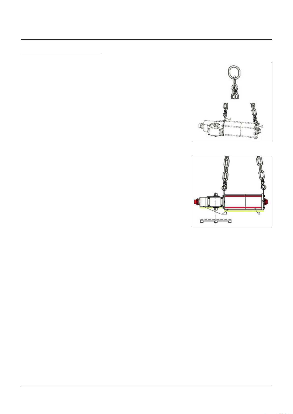
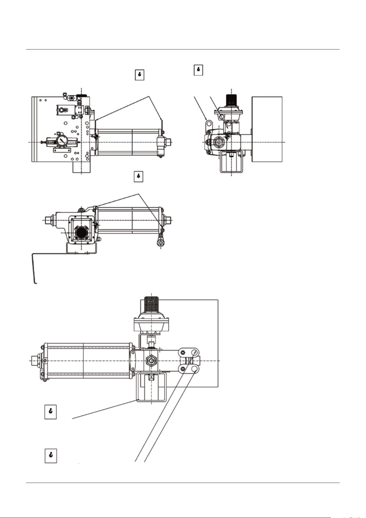
For a correct lifting procedure, please refer to
figure 3A, 3B.
A. Valve stem with horizontal axis
The actuator can also be lifted to assemble
directly onto the valve with stem with horizontal
axis. To make this operation easier, Biffi
suggest to move the lifting eyelet from its
standard position, and place it in the suggested
position, see figure 4.
FIGURE 3A, 3B
Lifting points for RPS actuators
3A
1, 2 = Lifting eyelets
3B
1 = Points of support
2 = Do not lay the actuator on tie-rods
WARNING
Do not lay the actuator on accessories (manual
hand pump, manual jackscrew, pneumatic control
system etc.)
4
Page 5
RPS SPRING RETURN PNEUMATIC ACTUATOR
INSTALLATION, OPERATION AND MAINTENANCE MANUAL
FRONT VIEW SIDE VIEW
Lifting eyelets (standard position)
A
Lifting eyelets suitable for vertical stem
valve mounting position (standard)
A
A
TOP VIEW
BACK SIDE VIEW
B
Lifting point to balance weight (suitable for slings)
(horizontal stem valve mounting position)
A
Lifting eyelets (horizontal stem valve mounting position)
FIGURE 4
A = Lifting eyelets
B = Lifting point (balancing)
5
Page 6
RPS SPRING RETURN PNEUMATIC ACTUATOR
INSTALLATION, OPERATION AND MAINTENANCE MANUAL
2.3 Storage
If the actuator needs storage, before
installation follow these steps:
• Place it on a wood surface in order not to
deteriorate the area of valve coupling.
• Make sure that plastic plugs are present on
the pneumatic and electrical connections
(if present).
• Check that the cover of the control group and
of the limit switch box (if any) are properly
closed.
If the storage is long-term or outdoor:
• Keep the actuator protected from direct
weather conditions.
• Replace plastic plugs of pneumatic and
electrical connections (if any) with metal
plugs that guarantee perfect tightness.
• Coat with oil, grease or protection disc, the
valve coupling area.
• Periodically operate the actuator (section 3.3).
2.4 Actuator assembly on the valve
2.4.1 Types of assembly
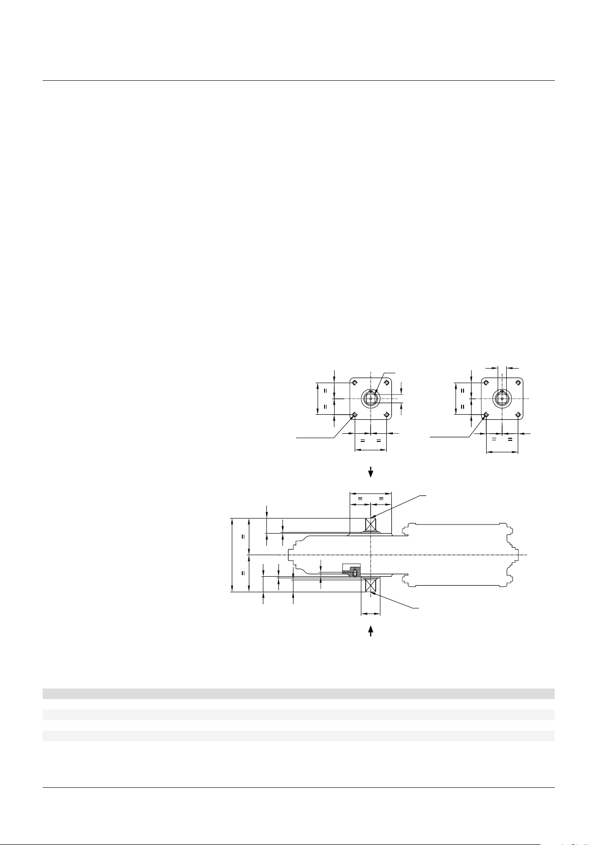
For coupling to the valve, the housing is
provided with a flange with threaded holes
according to Biffi standard tables (see figure 5).
The number, dimensions and diameter of the
holes are made in accordance with ISO 5211.
The actuator is provided with a spool piece
and a stem extension for coupling to the valve.
The assembly position of the actuator, with
reference to the valve, must comply with the
plant requirements (cylinder axis parallel or
perpendicular to the pipeline axis).
FIGURE 5
№4 threaded holes №4 threaded holes
View from X View from Y
ØF
B
ØC ØC
A
ØE
B
ØE
Y
A
IMPORTANT
To fix the actuator to the valve flange must be
ØH
Threaded hole ØN
used the stud bolts and nuts supplied by Biffi!
In case the actuator is supplied without stud bolts
and nuts the following materials must be used as
K
J
a minimum:
ASTM A 193 grade L7 for stud bolts
ASTM A 194 grade 4 for nuts
L
D
J
K
G
ØM
Threaded hole ØN
X
COUPLING DIMENSIONS (mm)
Actuator model A ± 0.2 B ± 0.2 ØC D ØE ØF G ØH K J L ØM ØN
RP 14/15 49.5 49.5 M8 10 16 21 23 66 30 3 140 40 M5
RP 30 72.1 72.1 M10 12 22 29 25 92 32 3 164 50 M5
RP 60 88.4 88.4 M12 15 28 37 34 112 42 3 204 60 M5
RP 120 99.0 99.0 M16 23 37 49 45 132 55 3 270 75 M8
NOTE
Both the actuator flanges can be used for the coupling to the valve or the mounting of ancillary equipments (positoner, limit switch box, etc. )
6
Page 7

RPS SPRING RETURN PNEUMATIC ACTUATOR
INSTALLATION, OPERATION AND MAINTENANCE MANUAL
2.4.2 Assembly procedure
IMPORTANT
Failure to comply with the following procedures
may impair product warranty.
WARNING
Installation, commissioning and maintenance and
repair works should be carried out by qualified
staff. A non-conforming assembly could be the
source of serious accidents.
For actuator assembly on the valve:
IMPORTANT
Check that the assembly position, as shown
on the documentation, complies with system’s
geometry. Check the consistency of the parts of
actuator-valve coupling.
• Operate the actuator so that it reaches the
position matching valve position (section 3.3).
• Lubricate valve stem with oil or grease.
• Properly clean and remove grease from
coupling flange surfaces.
• Connect, if supplied separately, the
adjustment insert to valve stem and fasten it
with the special fastening pins.
• Lift the actuator using the special lifting
points (section 2.2).
• Install the actuator so that valve stem inserts
in the coupling area. This coupling should be
made without forcing.
• Fasten the two parts with the threaded
connections (screws, tie rods, nuts). If
holes of coupling flanges are not aligned,
adequately operate the actuator if necessary
move the mechanical stops backwards
(section 3.4).
• Fasten threaded connections. Please refer to
table 1.
The screwing values in table 1 were calculated
considering the materials ASTM A320 grade L7
for screws or tie rods and ASTM A194 grade 2H
for the nuts.
2.5 Pneumatic connections
Connect the actuator to the pneumatic feed
line with fittings and pipes in accordance to
the plant specifications. They must be sized
correctly in order to guarantee the necessary
air flow for the operation of the actuator, with
pressure drops not exceeding the maximum
allowable value.
The shape of the connecting piping must
TABLE 1 - NUTS TIGHTENING TORQUE
Threading Tightening torque (Nm)
M8 20
M10 40
M12 70
M16 160
not cause excessive stress to the inlets of
the actuator. The piping must be suitably
fastened so as not to cause excessive stress
or loosening of threaded connections, if the
system undergoes strong vibrations.
Every precaution must be taken to ensure
that any solid or liquid contaminants which
may be present in the pneumatic pipe-work
to the actuator are removed to avoid possible
damages to the unit or loss of performance.
The inside of the pipes used for the connections
must be well cleaned before use: wash them
with suitable substances and blow through
them with air or nitrogen.
The ends of the tubes must be well deburred
and cleaned. Once the connections are
completed, operate the actuator and check that
it functions correctly, that the operation times
meet the plant requirements and that there are
no leakages in the pneumatic connections.
2.6 Electrical connections (if any)
WARNING
The connections should be made by qualified staff.
Before carrying out any operation, cut line
power off.
Safety provisions as per CEI 64-8 regulation
should be complied with (same as IEC 60364).
Connect the electrical feed, control and
signal lines to the actuator, by linking them
up with the terminal blocks of the electrical
components. In order to do this, the housing
covers must be removed without damaging the
coupling surfaces, the O-rings or the gaskets.
Remove the plugs from the cable entries. For
electrical connections use components (cable
glands, cables, hoses, conduits) which meet the
requirements and codes applicable to the plant
specifications (mechanical protection and/or
explosion-proof protection). Screw the cable
glands tightly into the threaded inlets, so as
to guarantee the weatherproof and explosionproof protection (when applicable). Insert the
connection cables into the electrical enclosures
through the cable glands, and connect the
cable wires to the terminals according to the
applicable wiring diagram. If conduits are used,
it is advisable to carry out the connection to the
electrical enclosures by inserting hoses so as
not to cause anomalous stress on the housing
cable entries. Replace the plastic plugs of the
unused enclosure entries by metal ones, to
guarantee perfect weatherproof tightness and
to comply with the explosion-proof protection
codes (where applicable).Once the connections
are completed, check that the controls and
signals work properly.
2.7 Commissioning
WARNING
Installation, commissioning and maintenance and
repair works should be made by qualified staff.
Any calibration relative to functional aspects of
the actuator are preset at the factory, except the
angular stroke setting because for this setting
operation, the actuator must be placed on to the
valve (see section 3.4).
Before any modifications please contact Biffi.
Upon actuator commissioning please carry out
the following checks:
• Check that the pressure and quality of the
air supply (filtering degree, dehydration) are
as prescribed. Check that the feed voltage
values of the electrical components (solenoid
valve coils, microswitches, pressure switches,
etc.) are as prescribed.
• Check that the actuator controls work
properly (remote control, local control,
emergency controls, etc.).
• Check that the required remote signals (valve
position, air pressure, etc.) are correct.
• Check that the setting of the components of
the actuator control unit (pressure regulator,
pressure switches, flow control valves, etc.)
meet the plant requirements.
• Check there are no leakages in the pneumatic
connections. If necessary tighten the nuts of
the pipe fittings.
• Remove all rust and, in accordance with the
applicable painting specifications, repair
paint-coat that has been damaged during
transport, storage or assembly.
7
Page 8
RPS SPRING RETURN PNEUMATIC ACTUATOR
INSTALLATION, OPERATION AND MAINTENANCE MANUAL
3 OPERATION AND USE
3.1 Operation description
The air pressurizes the cylinder chamber and
this pressure starts the linear motion of the
piston and the consequent rotation motion
of the rack and pinion mechanism, to which
the valve stem is coupled, in one direction.
The operation in the opposite direction is
made by the linear movement generated from
the spring releasing, when the opposition
of pneumatic supply is discharged from the
cylinder.
For local or remote operations related
to the actuator, please refer to technical
documentation furnished with delivery
actuators (schematics, overall dimensions and
parts list).
IMPORTANT
Typical general schematics for various
applications are follow attached for information
only, various control systems are furnished only
at customer demand:
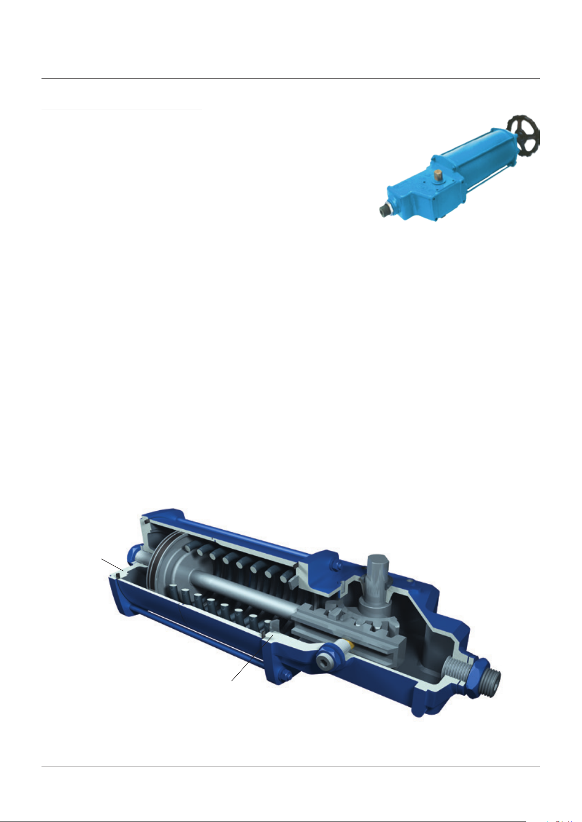
Manual override for RPS spring return
pneumatic actuator
Actuator manual emergency operation in
opposition to the spring action, is performed
by rotating the jackscrew by a wrench or by a
handwheel (available on request).
FIGURE 7
FIGURE 6
Pneumatic
connection
Pneumatic
connection
8
Page 9
RPS SPRING RETURN PNEUMATIC ACTUATOR
INSTALLATION, OPERATION AND MAINTENANCE MANUAL
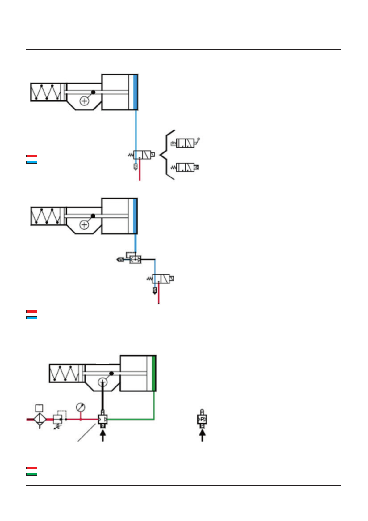
FIGURE 8A
Pressurized air
Atmospheric pressure air
FIGURE 8B
On-Off service: three way control valve
The diagram shows the simplest On-Off
1
control. The control valve (2) has two positions.
In one position the gas supply pressure is
connected to the cylinder chamber, and the
actuator performs the “pneumatic” operation.
In the other position the cylinder is connected
to the exhaust and the actuator moves under
the operation of the spring.
The control valve can have many types of
actuating devices (solenoid, manual control,
pneumatic pilot, spring, etc.).
Solenoid
control
2
Manual
control
Pneumatic
pilot control
The spring return control valves allow
“failsafe” operation.
1
On-Off service: quick spring operation
When fast action is required under spring
operation, a quick exhaust valve (3) is installed
in the cylinder directly port to exhaust the gas
from the cylinder directly to the atmosphere.
3
When the control valve (2) opens to the
atmosphere a differential pressure is created
across the quick exhaust valve (3) causing it
2
to open. The resultant high flow capacity from
cylinder to atmosphere allows quick spring
operation of the actuator.
Pressurized air
Atmospheric pressure air
FIGURE 8C
2
Pneumatic
Pressurized air (supply)
Reduced pressure air
3
positioner
4
1
P
5
P
Pneumatic
control signal
Electropneumatic
positioner
Electric
controlsignal
Modulating service
When modulating control is required as a
function of a pneumatic or electric control
signal, a positioner (5) is used, which controls
the supply to the actuator cylinder to keep the
valve in the required angular position.
The positioner has a mechanical linkage to the
actuator, for a feedback of the valve position.
9
Page 10
RPS SPRING RETURN PNEUMATIC ACTUATOR
INSTALLATION, OPERATION AND MAINTENANCE MANUAL
3.2 Residual risks
WARNING
The actuator has parts under pressure. Use the
due caution.
Use individual protections provided for by the laws
and provisions in force.
3.3 Operations
The operations are carried out sending the
proper signal through the control system in
compliance with customer specifications.
Please refer to the functional diagram and
specific documentation supplied.
3.4 Calibration of the angular stroke
It is important that the mechanical stops of the
actuator (and not those of the valve) stop the
angular stroke at both extreme valve position
(fully open and fully closed), except when this
is required by the valve operation (e.g. metal
seated butterfly valves).
The setting of the angular stroke is performed
by adjusting the travel stop screws of the
cylinder end flange and of the housing wall.
The setting of the open valve position is
performed by adjusting the travel stop screw
on the left side of the actuator (screwed in the
housing wall for spring to close actuators or
in the cylinder end flange for spring to open
actuators).
The setting of the closed valve position is
performed by adjusting the travel stop screw
on the right side of the actuator (screwed in
the cylinder end flange for spring to close
actuators or in the housing wall for spring to
open actuators).
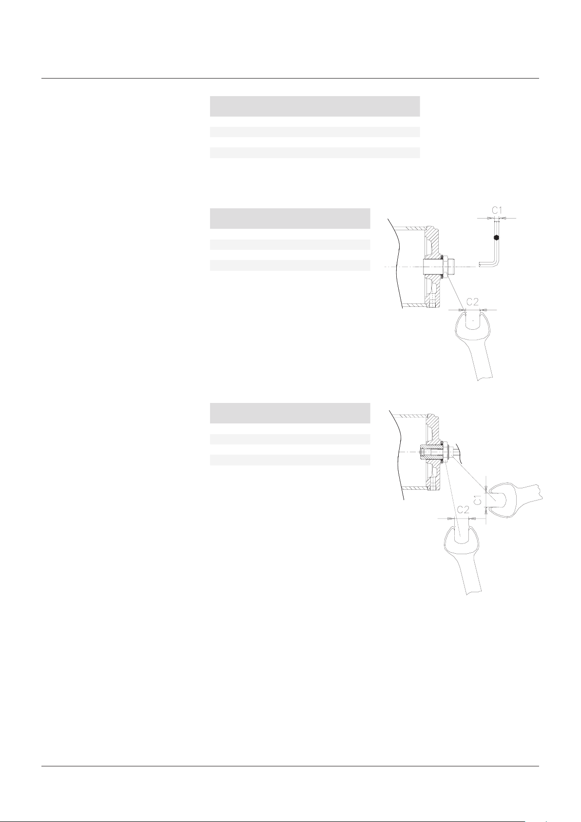
For the adjustment of the travel stop screws
proceed as follows (see figures 9A, 9B):
1. Loosen the lock nut with wrench C2.
2. If the actuator angular stroke is stopped
before reaching the end position (fully open
or closed), unscrew with wrench C1 the
travel stop screw by turning it anticlockwise,
until the valve reaches the right position.
When unscrewing the travel stop screw,
keep the lock nut still with a wrench so
that the sealing washer does not withdraw
together with the travel stop screw.
3. Tighten the lock nut (refer to torque table to
avoid accidental unscrewing of the lock nut).
4. If the actuator angular stroke is stopped
beyond the end position (fully open or closed
valve), screw the stop screw by turning it
clockwise until the valve reaches the right
position.
5. Tighten the lock nut (refer to torque table to
avoid accidental unscrewing of the lock nut).
Wrench C2
Actuator model Thread
RP 14/15 M30x2 41 150
RP 30 M40x2 50 350
RP 60 M45x2 55 500
RP 120 M50x2 60 800
(mm)
Torque
FIGURE 9A, 9B
Wrench C1
Actuator model
RP 14/15 17 41
RP 30 17 50
RP 60 17 55
RP 120 17 60
(mm)
Wrench C2
(mm)
Without jackscrew manual override
Wrench C1
Actuator model
RP 15-MSJ/MHW 24 41
RP 30-MSJ/MHW 32 50
RP 60-MSJ/MHW 36 55
RP 120-MSJ/MHW 36 60
(mm)
Wrench C2
(mm)
With jackscrew manual override MSJ or
handwheel manual override MHW
(Nm)
10
Page 11
RPS SPRING RETURN PNEUMATIC ACTUATOR
INSTALLATION, OPERATION AND MAINTENANCE MANUAL
3.5 Calibration of the operating time
(optional- if foreseen)
The calibration of the operating time is made
according to customer requirements and to
technical data sheet included in technical
documentation. If necessary it’s possible to
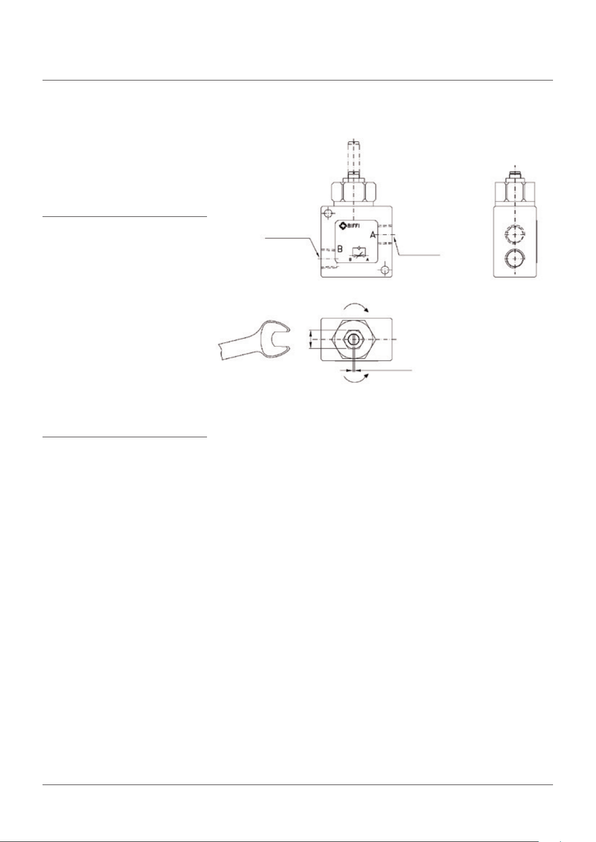
modify or reset the operating time through
the flow regulator valve placed on inlet of
pneumatic supply (figure 19).
4 OPERATIONAL TESTS AND INSPECTIONS
IMPORTANT
To ensure the guaranteed SIL Level, according
to IEC 61508, the functionality of actuator must
be checked with regular intervals of time, as
described following.
For safety related applications, the following
test operation has to be performed:
1. Full stroke of actuator once a year.
2. Partial stroking test at least every six
months (if applicable, please refer to
operating diagram and operate accordingly).
3. Visual inspection-checks , according to
section 5.1, but with a frequency of once
a year.
For standard applications please refer to
section 5.1.
5 MAINTENANCE
IMPORTANT
Before executing any maintenance operation, it
is necessary to close the pneumatic supply line
and discharge pressure from the cylinder of the
actuator and from the control unit (if foreseen).
WARNING
Installation, commissioning and maintenance
and repair works should be carried out by
qualified staff.
5.1 Periodic maintenance
RPS actuators are designed to operate longterm in heavy-duty operating conditions,
without maintenance needs.
IMPORTANT
Periodicity and regularity of inspections is
particularly influenced by specific environmental
and working conditions.
They can be initially determined experimentally
and then be improved according to actual
maintenance conditions and needs.
FIGURE19
Example of operating time adjustment by flowregulator valve (please refer to specific operating
diagram)
Pneumatic connection
Pneumatic connection
(close) screw for decrease speed
Wrench
Screwdriver
(open) unscrew for increase speed of operation
Anyway every 2 years of operation the following
is recommended:
• Check that the actuator operates the valve
correctly and with the required operating
times. If the actuator operation is very
infrequent, carry out a few opening and
closing operations with all the existing
controls (remote control, local control,
emergency controls, etc.), if this is allowed by
the conditions of the plant.
• Check all the paint-coat of the actuator.
If some areas are damaged, repair the
paint-coat according to the applicable
specification.
• Check there are no pneumatic leakages If
necessary tighten the nuts of the pipe-fittings.
• Check the integrity of worn out parts (gaskets,
pads etc.).
• If there is an air filter on the actuator, bleed
the condense water accumulated in the cup
by opening the drain cock. Disassemble the
cup periodically and wash it with soap and
water; disassemble the filter: if this is made
up of a sintered cartridge, wash it with nitrate
solvent and blow through with air. If the filter
is made of cellulose, it must be replaced
when clogged.
11
Page 12

RPS SPRING RETURN PNEUMATIC ACTUATOR
INSTALLATION, OPERATION AND MAINTENANCE MANUAL
5.2 Extraordinary maintenance
If there are leaks in the pneumatic cylinder or a
malfunction in the mechanical components, or
in case of scheduled preventive maintenance,
the actuator must be disassembled and
seals must be replaced with reference to
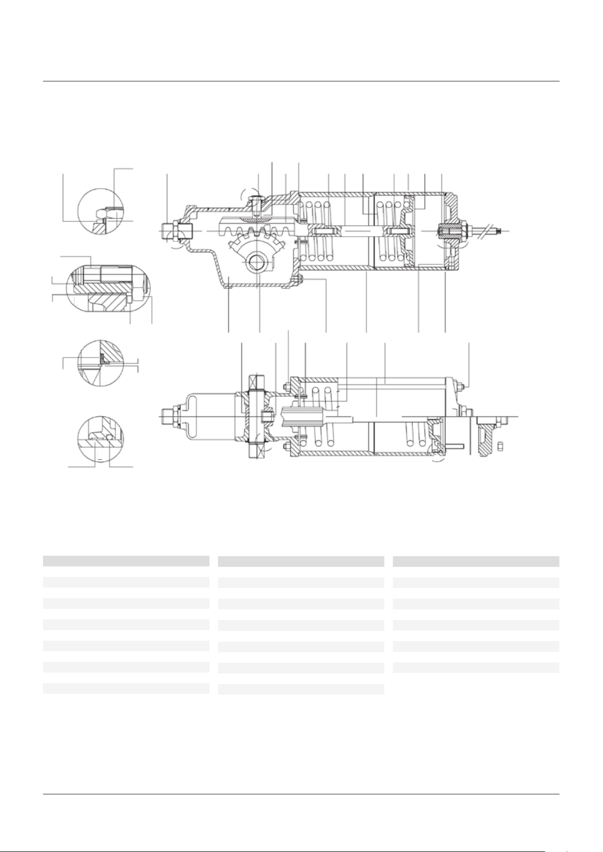
the following general sectional drawing and
adopting the following procedures.
5.2.1 Replacement of cylinder seals
(refertosectional drawing, figure 20)
IMPORTANT
Before carrying out any maintenance operation, it
is necessary to close the pneumatic feed line and
exhaust the pressure from the actuator and from
the control unit, to ensure safety of maintenance
staff.
Installation, commissioning and maintenance and
repair works should be carried out by qualified
staff.
Before carrying out any operation, cut power off
from the electrical line.
Replacement of cylinder seals
1. Measure the protrusion of the stop screw
(30) with reference to the end flange (4)
surface, so as to be able to easily restore
the setting of the actuator mechanical stop,
once the maintenance procedures have
been completed.
2. Loosen the lock nut (10) and unscrew the
stop screw (30) together with the nut (10),
the washer (28) and the sealing washer (17).
3. Unscrew the nuts (25) from the tie rod (14)
from the side of the end flange: they must
be gradually unscrewed all at the same
time.
4. Slide off the end flange (4) and the tube (13).
The spacer tube (33) must remain in place.
Take care not to damage the plane surfaces
of the tube ends.
4. Carefully clean the ends of the cylinder
tube (13) and of the spacer tube (33), which
must fit together, to remove any trace of the
sealant which assures tightness.
5. Remove the sealing washer (17) from the
travel stop screw (30). Carefully clean and
lubricate the travel stop screw thread and
the surface of the end flange area, where
the sealing washer is.
6. Screw the new sealing washer onto the travel
stop until it is in contact with the nut (10).
7. Assemble the washer (28) onto the sealing
washer (17).
Reassemble
1. Assemble the new cylinder gasket (7) on its
seat on the end flange (4).
2. Carefully clean the inside of the tube
(13) and check that the entire surface,
particularly that of the bevels, is not
damaged. Lubricate the inside surface of
the tube and the bevels at the ends.
3. Spread some sealant LOCTITE 510, or
equivalent, on the cylinder tube end (13),
which is connected to the spacer tube (33).
4. Slide the cylinder tube (13) onto the piston
taking care not to damage the piston O-ring
(24).
5. Assemble the end flange (4) centring it
on the tube (13). Assemble the nuts (25)
onto the tie rod (14). Tighten the nuts to
the recommended torque (see table),
alternating between opposite corners.
Screw the travel stop screw into the
threaded hole of the end flange until it
reaches its original position (the same
protrusion with reference to the flange
surface).
6. Check that the sealing washer (17) and
the washer (28) are in contact with the end
flange surface.
7. Tighten the lock nut (10).
Seals replacement
Prior to reassemble check that the actuator
components are in good conditions and clean.
Lubricate all the surfaces of the parts, which
move in contact with other components, by
recommended by recommended oil (SHELL
Omala S4 WE 320 or equivalent). If the O-ring
must be replaced, remove the existing one
from its groove, clean the groove carefully and
lubricate it with protective oil film. Assemble
the new O-ring into its groove and lubricate it
with a protective oil film.
1. Replace the O-ring (24) and the piston guide
sliding ring (20).
2. Remove the existing gasket (7) from its seat
in the end flange (4).
3. Carefully clean the seat of the gasket in the
end flange (4) and the plane surface, of the
tube end (13), which is in contact with the
gasket (7).
12
Page 13

RPS SPRING RETURN PNEUMATIC ACTUATOR
INSTALLATION, OPERATION AND MAINTENANCE MANUAL
Replacement of mechanism seals
To replace the O-rings of the shaft (6) proceed
as follows:
1. Remove the retainer ring (21).
2. Disassemble the shoulder washer (8).
Remove the existing O-ring (23) from its
groove. Clean the groove and the shaft
carefully and lubricate it with protective oil
film.
3. Assemble the new O-ring into its groove and
lubricate it with protective oil or a grease
film. Assemble the shoulder washer (8).
Assemble the retainer ring (21).
If the sealing washer (17) has to be replaced,
measure the protrusion of the stop screw
(30) with reference to the housing (1) surface,
so as to be able to easily restore the setting
of the actuator mechanical stop, once the
maintenance procedures have been completed.
1. Loosen the lock nut (10) and remove the
stop screw (30) together with the nut (10),
the washer (28) and the sealing washer
(17). Remove the sealing washer (17) from
the stop screw (30). Carefully clean and
lubricate the stop screw thread and the
surface on the housing area, where the
sealing washer is.
2. Screw the new sealing washer onto the stop
screw until it is in contact with the nut (10).
Assemble the washer (28) onto the sealing
washer (17).
3. Screw the stop screw into the threaded hole
of the housing until it reaches its original
position (the same protrusion with reference
to the housing surface). Check that the
sealing washer (17) and the washer (28) are
in contact with the housing surface. Tighten
the lock nut (10).
If the sealing washer (18) has to be replaced,
measure the protrusion of the thrust bearing
screw (15) with reference to the housing (1)
surface, so as to be able to easily restore the
setting of the position of the thrust bearing
sliding block with reference to the rack once
the maintenance procedures have been
completed.
1. Loosen the lock nut (26) and remove the
screw (15) together with the sliding block
(19), the nut (26), the washer (27) and the
sealing washer (18). Remove the sealing
washer (18) from the screw (15). Carefully
clean and lubricate the screw thread and
the surface of the housing area, where the
sealing washer is.
2. Screw the new sealing washer onto the
screw until it is in contact with the nut (26).
3. Assemble the washer (27) onto the sealing
washer (18).
4. Screw the thrust bearing screw (15),
complete with the sliding block (19), into the
threaded hole of the housing until it reaches
its original position (the same protrusion
with reference to the housing surface).
5. Check that the sealing washer (18) and the
washer (27) are in contact with the housing
surface. Tighten the lock nut (26).
IMPORTANT
AFTER MAINTENANCE OPERATIONS CARRY OUT
A FEW ACTUATOR OPERATIONS TO CHECK THAT
ITS MOVEMENT IS REGULAR AND THAT THERE
IS NO AIR LEAKAGE THROUGH THE SEALS.
13
Page 14
RPS SPRING RETURN PNEUMATIC ACTUATOR
INSTALLATION, OPERATION AND MAINTENANCE MANUAL
FIGURE 20
RPS spring return pneumatic actuator
19
27
26
A
A
18
15
5
7
16
12
22
2230
*1313
*2
B
B1
*3
B
17
28
10
6
1 2
31
25
29
32
11
33
14
4
25
7
8
23
20
C
21
D
24
C
D
PARTS LIST
Item Description
1 Housing
2 Pinion
3 Piston
4 End flange
5 Rack
6 Shaft
7 Cylinder gasket
8 Shoulder washer
10 Nut
11 Spring retainer disk
12 Rack spacer rod
13 Cylinder tube
Item Description Item Description
14 Tie rod
15 Thrust bearing screw
16 Spring
17 Sealing washer
18 Sealing washer
19 Sliding block
20 Piston guide sliding ring
21 Retainer ring
22 Screw
23 O-ring
24 O-ring
25 Nut
26 Nut
27 Washer
28 Washer
30 Travel stop screw
31 Screw
32 Plug
33 Spacer tube
*1 Stop setting screw
*2 Manual override jack screw
*3 O-ring
* applicable to RPS with handwheel manual override
14
Page 15

RPS SPRING RETURN PNEUMATIC ACTUATOR
INSTALLATION, OPERATION AND MAINTENANCE MANUAL
5.3 Lubrication of mechanism
For normal duty the rack-and-pinion
mechanism of the actuator is lubricated
'forlife'.
In case of high load and high frequency of
operation it may be necessary to periodically
restore lubrication: it is advisable to apply a
generous coating of grease on the contact
surfaces of moving parts, especially on the
surface of the rack in contact with the thrust
bearing sliding block and on the teeth of the
rack and pinion.
For this operation proceed as follows:
1. Disassemble the actuator from the valve.
2. Measure the protrusion of the stop screw
(30) with reference to the end flange surface
(4), so as to be able to easily restore its
setting once the maintenance procedures
have been completed.
3. Loosen the lock nut and unscrew the stop
screw until it is removed.
4. Remove the nuts (25) from the tie rod (14) at
the end flange side: they must be gradually
unscrewed all at the same time so as to
release the thrust of the spring against the
flange.
5. Slide off the end flange (4) and the cylinder
tube (13).
6. Measure the protrusion of the thrustbearing screw (15), with reference to the
housing surface, so as to be able to restore
the right working position of the thrust
bearing sliding block with reference to the
rack once the maintenance procedures have
been completed.
7. Remove from the actuator the complete
spring module, the main components of
which are the piston (3), the spring (16), the
rack spacer rod (12), the spring retainer disk
(11) and the rack (5).
8. Remove the spacer tube (33).
9. Lubricate abundantly the teeth of the rack
and pinion and the surface of the rack in
contact with the thrust bearing sliding block.
Use recommended grease.
Prior to reassemble:
1. Check that the actuator components are in
good conditions and clean.
2. Substitute the gaskets and the O-rings if
worn or damaged.
3. Assemble all the components, taking care
not to damage the seals.
The following grease is used by Biffi for
standard working temperature and suggested
for re-lubrication (see table).
AGIP MU/EP/2 AEROSHELL GREASE 7 or equivalent
To be used in standard temperature conditions
(-30°C/+85°C)
NLGI consistency: 2
Worked penetration: 280 dmm
ASTM dropping point: 185°C
Base oil viscosity at 40°C: 160 mm²/s
ISO classification: L-X-BCHB 2
DIN 51 825: KP2K - 20
Equivalent to:
ESSO BEACON EP2
BP GREASE LTX2
SHELL ALVANIA GREASE R2
ARAL ARALUB HL2
CHEVRON DURALITH GREASE EP2
CHEVRON SPHEEROL AP2
TEXACO MULTIFAK EP2
MOBILPLEX 47
PETROMIN GREASE EP2
To be used in low temperature conditions
(-60°C/+65°C)
Color: Buff
Physical state: Semi-solid at ambient temperature
Odor: Slight
Density: 966 kg/m³ at 15°C
Flash point: >215°C (COC)(based on synthetic oil)
Dropping point: 260°C (ASTM D-566)
Product code: 001A0065
Infosafe no.: ACISO GB/eng/C
5.4 Dismantling and demolition
WARNING
Before starting the disassembly a large area
should be created around the actuator so to allow
any kind of movement without problems of further
risks created by work-site.
Before disassembling the actuator it is necessary
to close the pneumatic feed line and discharge
pressure from the cylinder of the actuator, from
the control unit and from the accumulator tank,
if present.
The opposition of pneumatic supply is
discharged from the cylinder by the linear
movement generated from the spring
releasing. It moves actuator and consequently
the valve, in hits fail safe position.
If actuator is still mounted onto the valve,
loosen the threaded connections between valve
and actuator (screws, tie rods, nuts)
Lift the actuator using the proper lifting points
(see sect. 2.2).
If the actuator needs storage, before
demolition, see chapter 2.3
WARNING
The demolition of the actuator both concerning
any electrical and mechanical parts should be
made by specialized staff.
Separate the parts composing the actuator
according to their nature (ex. metallic, and
plastic materials, fluids etc.) and send them
to differentiated waste collection sites, as
provided for by the laws and provisions in force.
15
Page 16
RPS SPRING RETURN PNEUMATIC ACTUATOR
INSTALLATION, OPERATION AND MAINTENANCE MANUAL
6 TROUBLESHOOTING
6.1 Failure or breakdown research
Event Possible cause Remedy
Actuator does not work 1. Lack of power supply 1. Restore it
2. Clogged filter 2. Clean or replace the cartridge
3. Blocked valve 3. Repair or replace
4. Failure of the spring 4. Call Biffi Customer Service
5. Failure of the control group 5. Call Biffi Customer Service
6. Low supply pressure 6. Restore (section 1.4)
Actuator too slow 1. Low supply pressure 1. Restore (section 1.4)
2. Wrong calibration of flow regulator valves 2. Restore (section 3.6)
3. Wear of the valve 3. Replace
Actuator too fast 1. High supply pressure 1. Restore (section 1.4)
2. Wrong calibration of flow regulator valves 2. Restore (section 3.6)
Leakages on hydraulic circuits 1. Deterioration and/or damage to gaskets 1. Call Biffi Customer Service
Incorrect position of the valve 1. Wrong adjustment of mechanical stops 1. Restore (section 3.4)
2. Wrong warning of microswitches 2. Restore (section 3.5)
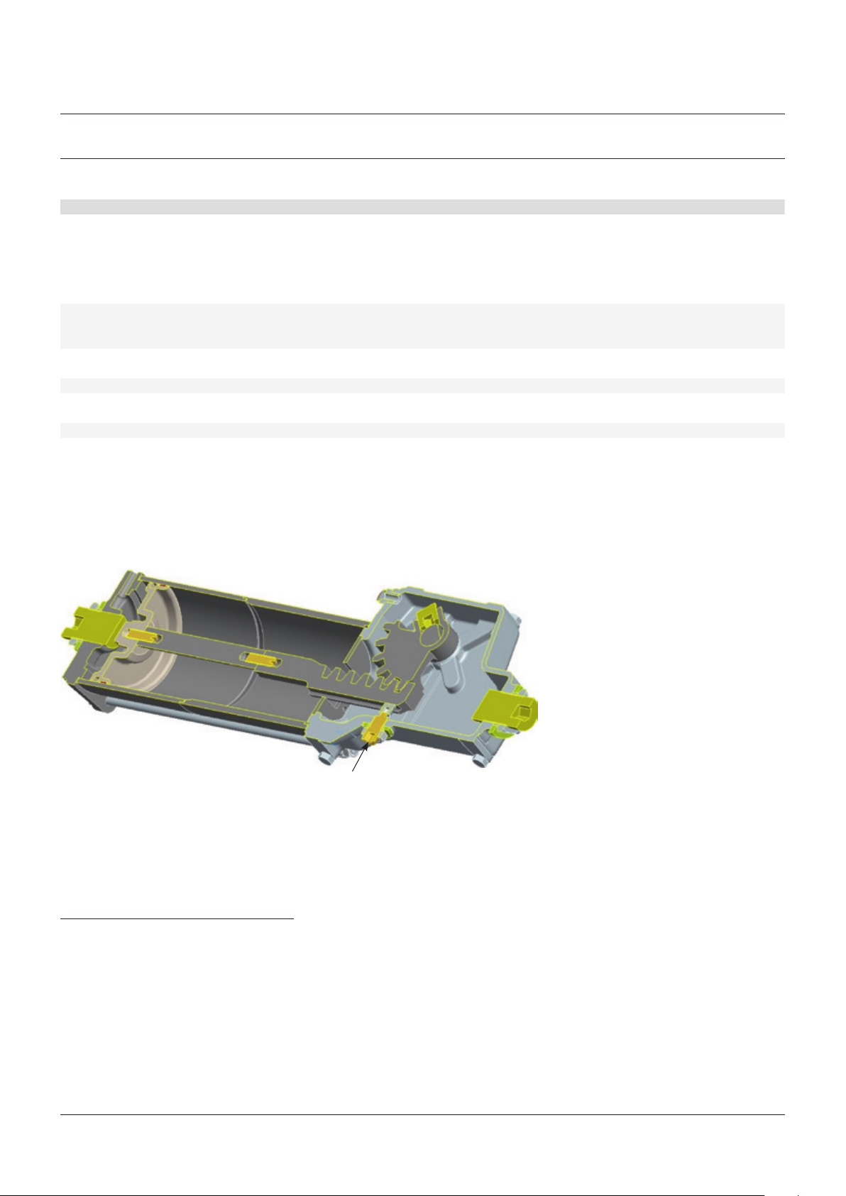
Irregular movement of actuator or lower torque value 1. Wrong adjustment or unscrewing of thrust bearing-screw 1. See figure 21 below
FIGURE 21
Restore the correct position of thrust bearing-screw
7 LAYOUTS
7.1 Spare parts order
For spare parts order to the relevant Biffi
office please make reference to Biffi order
confirmation concerning all the supply, and
serial number of the actuator (section 1.2) for
any specific spare part for a specific actuator
model.
Please send every spare-parts request to:
Biffi Italia S.r.l.
Servizio Assistenza Tecnica Clienti
E-mail: spareservice
@biffi.it
Please specify:
1. Actuator model
2. Biffi acknowledgement
3. Spare parts code
4. Quantity
5. Transport condition
6. Involved people
Please refer to figure 20 section 5.2.1:
Screw the thrust bearing screw (15), complete
with the sliding block (19), into the threaded
hole of the housing until it reaches the correct
original position.
Check that the sealing washer (18) and the
washer (27) are in contact with the housing
surface. Tighten the lock nut (26).
16
Page 17
RPS SPRING RETURN PNEUMATIC ACTUATOR
INSTALLATION, OPERATION AND MAINTENANCE MANUAL
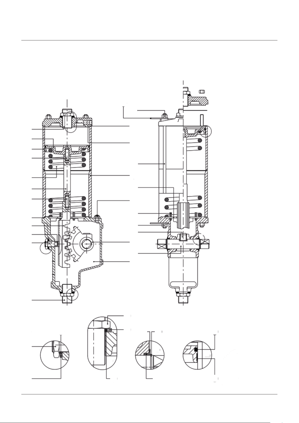
7.2 Parts list for maintenance and replacing procedure
FIGURE 22
Rack and pinion mechanism RPS S2-A1/B1/C1 single acting pneumatic actuator
9
B
25
30
13
22
16
12
22
19
15
7
3
7
5
A
4
14
36
11
32
29
25
31
2
6
1
D
C
30
26
27
B
10
18
28
21
8
24
C
A
D
B
17
23
20
17
Page 18

RPS SPRING RETURN PNEUMATIC ACTUATOR
INSTALLATION, OPERATION AND MAINTENANCE MANUAL
PARTS LIST - RPS S2-A1/B1/C1
Item Qty Description Material
1 1 Housing Nodular cast iron
2 1 Pinion Nodular cast iron
3 1 Piston Carbon steel
4 1 End flange Carbon steel
5 1 Rack Nodular cast iron
6 1 Shaft Alloy steel
7* 2 Cylinder gasket NBR
8* 2 Shoulder washer Nylon
9 2 Lifting eyelet Carbon steel
10 2 Nut Carbon steel
11 1 Spring retainer disk Carbon steel
12 1 Rack spacer rod Carbon steel
13 1 Cylinder tube Nickel plated carbon steel
14 4 Tie rod Alloy steel
15 1 Thrust bearing screw Alloy steel
16 1 Spring Alloy steel
17* 2 Sealing washer PVC
18* 1 Sealing washer PVC
19 1 Sliding block Bronze
20* 1 Piston guide sliding ring PTFE + graphite
21* 2 Retainer ring Spring steel
22 1 Screw Alloy steel
23* 2 O-ring NBR
24* 1 O-ring NBR
25 8 Nut Carbon steel
26 1 Nut Carbon steel
27 1 Washer Carbon steel
28 2 Washer Carbon steel
29 4 Spring pin Carbon steel
30 2 Travel stop screw Carbon steel
31 1 Screw Alloy steel
32 1 Plug Aluminium + bronze + steel
36 1 Spacer tube Carbon steel
* Recommended spare parts
18
Page 19
RPS SPRING RETURN PNEUMATIC ACTUATOR
INSTALLATION, OPERATION AND MAINTENANCE MANUAL
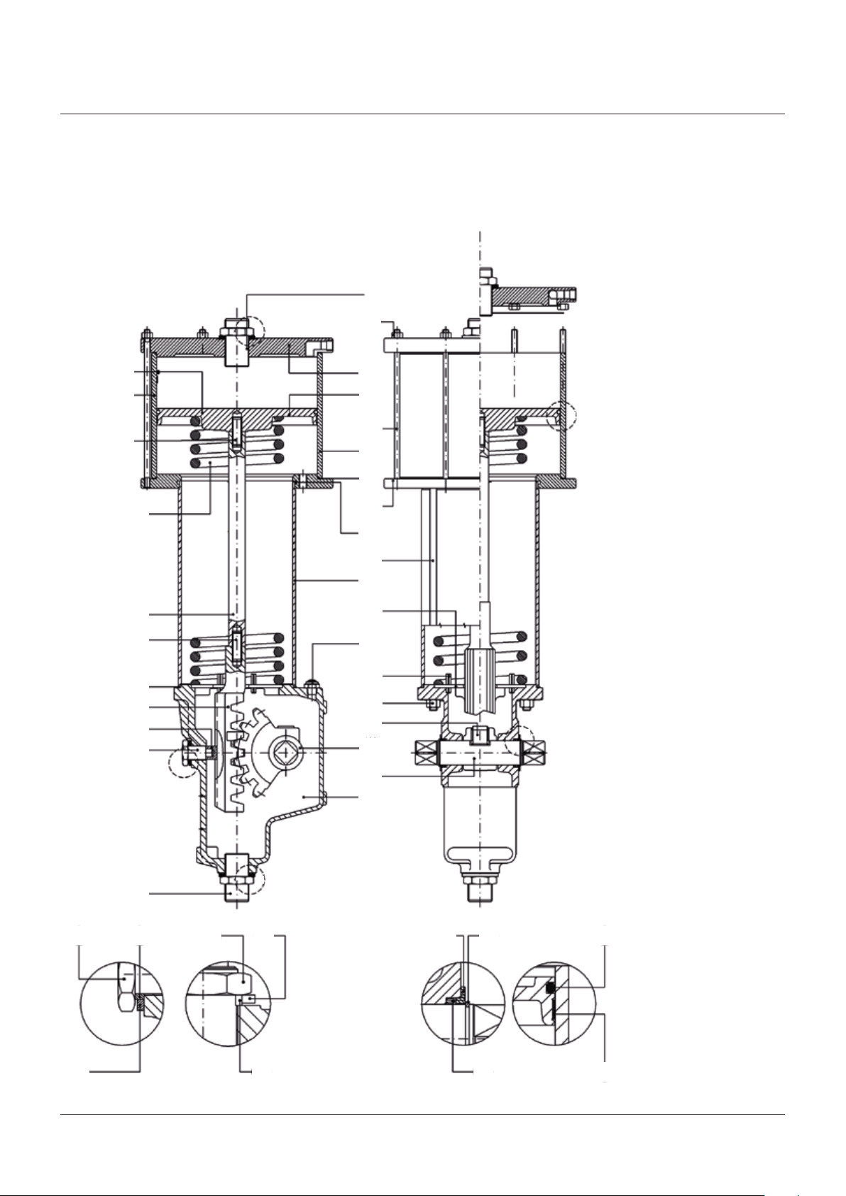
FIGURE 23
RPS 2.4 / RPS 3.1 single acting pneumatic actuator
30
13
42
39
13
38
37
40
14
36
11
32
29
25
31
41
31
4
3
2
D
C
B
3
16
12
22
7
5
19
15
26 18
A
27
30
A
B
10 28
6
1
8
21
24
C
B
17
23
D
20
19
Page 20

RPS SPRING RETURN PNEUMATIC ACTUATOR
INSTALLATION, OPERATION AND MAINTENANCE MANUAL
PARTS LIST - RPS 2.4 / RPS 3.1
Item Qty Description Material
1 1 Housing Nodular cast iron
2 1 Pinion Nodular cast iron
3 1 Piston Carbon steel
4 1 End flange Carbon steel
5 1 Rack Nodular cast iron
6 1 Shaft Alloy steel
7* 2 Cylinder gasket NBR
8* 2 Shoulder washer Nylon
9 -- -- -10 2 Nut Carbon steel
11 1 Spring retainer disk Carbon steel
12 1 Rack spacer rod Carbon steel
13 1 Cylinder tube Nickel plated carbon steel
14 4 Tie rod Alloy steel
15 1 Thrust bearing screw Alloy steel
16 1 Spring Alloy steel
17* 2 Sealing washer PVC
18* 1 Sealing washer PVC
19 1 Sliding block Bronze
20* 1 Piston guide sliding ring PTFE + graphite
21* 2 Retainer ring Spring steel
22 1 Screw Alloy steel
23* 2 O-ring NBR
24* 1 O-ring NBR
25 8 Nut Carbon steel
26 1 Nut Carbon steel
27 1 Washer Carbon steel
28 2 Washer Carbon steel
29 4 Spring pin Carbon steel
30 2 Travel stop screw Carbon steel
31 1 Screw Alloy steel
32 1 Plug Aluminium + bronze + steel
33 -- -- -34 -- -- -35 -- -- -36 1 Spacer tube Carbon steel
37 1 Intermediate flange Carbon steel
38* 2 O-ring NBR
39 4 Tie rod Alloy steel
40* 1 O-ring NBR
41 4 Nut Carbon steel
43 1 Screw Carbon steel
* Recommended spare parts
20
Page 21

RPS SPRING RETURN PNEUMATIC ACTUATOR
INSTALLATION, OPERATION AND MAINTENANCE MANUAL
8 DATE REPORT FOR MAINTENANCE OPERATIONS
Last maintenance operation date:
(in factory, on delivery): ….....................................
....…...............… exec. by: …...............................……
....…...............… exec. by: …...............................……
....…...............… exec. by: …...............................……
Next maintenance operation date:
....…...............… exec. by: …...............................……
....…...............… exec. by: …...............................……
....…...............… exec. by: …...............................……
Start-up date:
(in factory, on delivery): .……………………................
(on plant): ….....................................
Biffi reserves the right to change product designs and specifications without notice.
Biffi Italia S.r.L.
Località Caselle San Pietro, 420, 29017 Fiorenzuola d'Arda (PC) ITALY Ph: +39 (0)523 944 411 E-mail: biffi_italia@biffi.it www.biffi.it
21
 Loading...