

Page 1
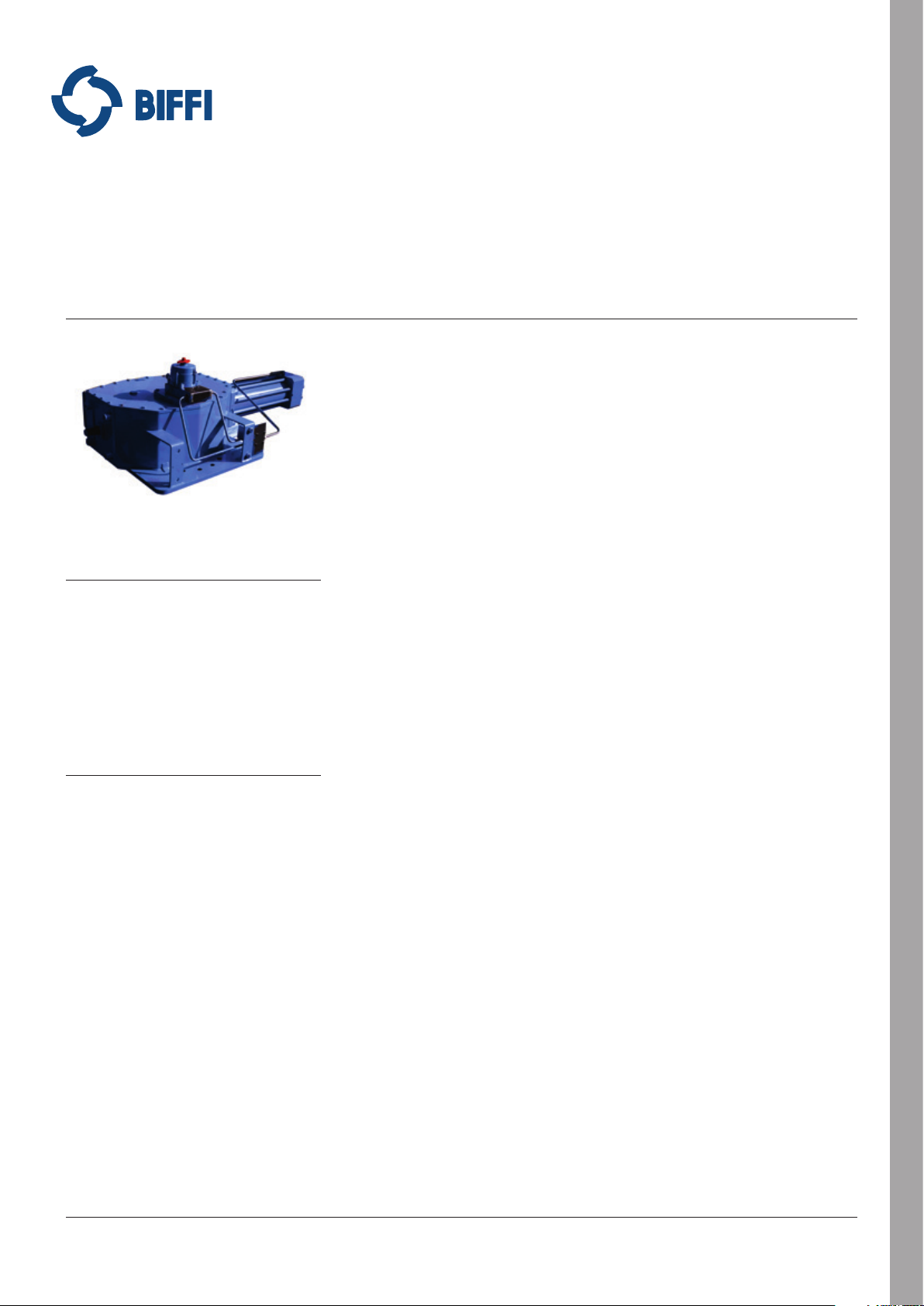
BIFFI OLGA-H HIGH PRESSURE DOUBLE ACTING HYDRAULIC ACTUATOR
INSTALLATION, OPERATION AND MAINTENANCE MANUAL
Before installation these instructions must be read fully and understood
1.1.1 Applicable regulation
EN ISO 12100-1: 2005: Safety of machinery
– Basic notions, general design principles�
Part 1-Basic terminology, method�
EN ISO 12100-2: 2005: Safety of machinery
– Basic notions, general design principles�
Part 2-Technical principles and specification�
2006/42/EC: Machine directive�
97/23/EC: Directive for pressure PED
equipment�
2006/95/EC: Directive for low voltage
equipment�
2004/108/EC: Directive for the electromagnetic
TABLE OF CONTENTS
1 General warnings ������������������������������������������ 1
2 Installation ����������������������������������������������������� 3
3 Operation and use ����������������������������������������� 9
4 Operational tests and inspections�������������� 23
5 Maintenance� ����������������������������������������������� 23
6 Troubleshooting ������������������������������������������ 30
7 Layouts ��������������������������������������������������������� 30
8 Date report for maintenance operations ��� 39
1 GENERAL WARNINGS
IMPORTANT
The manual is an integral part of the machine. It
should be read carefully before carrying out any
operation and should be kept for future reference.
1.1 Generalities
Biffi� actuators are conceived, manufactured
and controlled according to a Quality Control
System in compliance with EN ISO 9001
international regulation�
compatibility�
94/9/EC: Directive and safety instructions for
use in hazardous area�
1.1.2 Terms and conditions
Biffi guarantees that all the items produced
are free of defects in workmanship and
manufacturing materials and meet relevant
current specifications, provided they are
installed, used and serviced according to the
instructions contained in the present manual�
The warranty can last either one year from
the date of installation by the initial user of the
product, or eighteen months from the date
of shipment to the initial user, depending on
which event occurs first� All detailed warranty
conditions are specified in the documentation
forwarded together with the product� This
warranty does not cover special products or
components not warranted by subcontractors,
or materials that were used or installed
improperly or were modified or repaired by
unauthorized staff� In the event that a fault
condition be caused by improper installation,
maintenance or use, or by irregular working
conditions, the repairs will be charged
according to applicable fees�
www.biffi.it Copyright © Biffi� All rights reserved�
VCIOM-03744-EN 17/12
Page 2
BIFFI OLGA-H HIGH PRESSURE DOUBLE ACTING HYDRAULIC ACTUATOR
INSTALLATION, OPERATION AND MAINTENANCE MANUAL
FIGURE 1
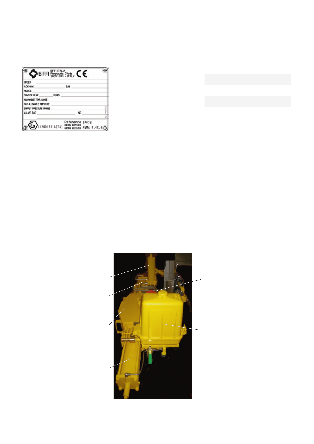
Data plate
1.2 Identification plate
It is forbidden to modify the information and the
marks without previous written authorization
by Biffi�
The plate fastened on the actuator contains the
following information (figure 1)�
1.3 Introducing the actuator
The hydraulic actuator series OLGA-H is
engineered and manufactured to provide
maximum torque output with minimum supply
pressure� OLGA-H actuators are suitable for
the operation of any quarter turn operation
such of ball, plug, butterfly valves or dampers,
in both On-Off and Modulating heavy duty
service�
The actuator (see figure 2) is made up of
a weatherproof Scotch yoke mechanism
transforming the linear movement of the
pneumatic cylinder (on closing or opening) into
the rotary movement, which is necessary for
operation� The angular stroke of the yoke is
adjustable between 82° and 98° by means of
the external mechanical stops screwed into the
left wall of the mechanism housing and into the
end flange of the pneumatic cylinder� The cover
of the Scotch yoke mechanism is arranged
for the assembly of the required accessories
(positioner, signalling limit switches, position
transducer, etc�) by means of proper matching
units� The above mentioned accessories are
operated by the actuator drive sleeve� The
housing of the Scotch yoke mechanism has a
flange with threaded holes to fix the actuator to
the valve either directly or, if required, with the
interposition of an adaptor flange or a mounting
bracket� The actuator yoke has a hole with
keyways suitable for the assembly of an insert
bush the internal hole of which is machined
(by Biffi or at customer's care), according to
the shape and dimensions of the valve stem�
Biffi can supply different types of control
system following customer's requirements�
The expected lifetime of actuator is
approximately 30 years�
1.4 Data sheet
Supply fluid Hydraulic oil, special version for
fire-resistant fluids
Operating
temperature
Supply pressure Standard ranging from 210 to
Maximum
torque
Standard: from -30°C to +100°C
Optional: from -60° to +140°C
352 bar
Up to 40�000 Nm - higher value
with special versions
Manual hand pump - MHP
Optional: for OLGA-H-MHP models
or second pneumatic cylinder for
“double-cylinders” models
Scotch yoke mechanism
FIGURE 2
Identification of actuator parts
(optional)
Hydraulic cylinder
Hydraulic cylinder
Valve position indicator
High pressure control valve
enclosure (optional)
2
Page 3
BIFFI OLGA-H HIGH PRESSURE DOUBLE ACTING HYDRAULIC ACTUATOR
INSTALLATION, OPERATION AND MAINTENANCE MANUAL
2 INSTALLATION
2.1 Checks upon actuator receipt
• Check that the model, the serial number of
the actuator and the technical data reported
on the identification plate correspond with
those of order confirmation (section 1�2)�
• Check that the actuator is equipped with the
fittings as provided for by order confirmation�
• Check that the actuator was not damaged
during transportation: if necessary renovate
the painting according to the specification
reported on the order confirmation�
• If the actuator is received already assembled
with the valve, its settings have already been
made at the factory�
If the actuator is delivered separately
from the valve, it is necessary to check,
and, if required, to adjust, the settings of
the mechanical stops (section 3�4) and of
microswitches (if any) (section 3�5)�
2.2 Actuator handling
IMPORTANT
The lifting and handling should be made by
qualified staff and in compliance with the laws and
provisions in force.
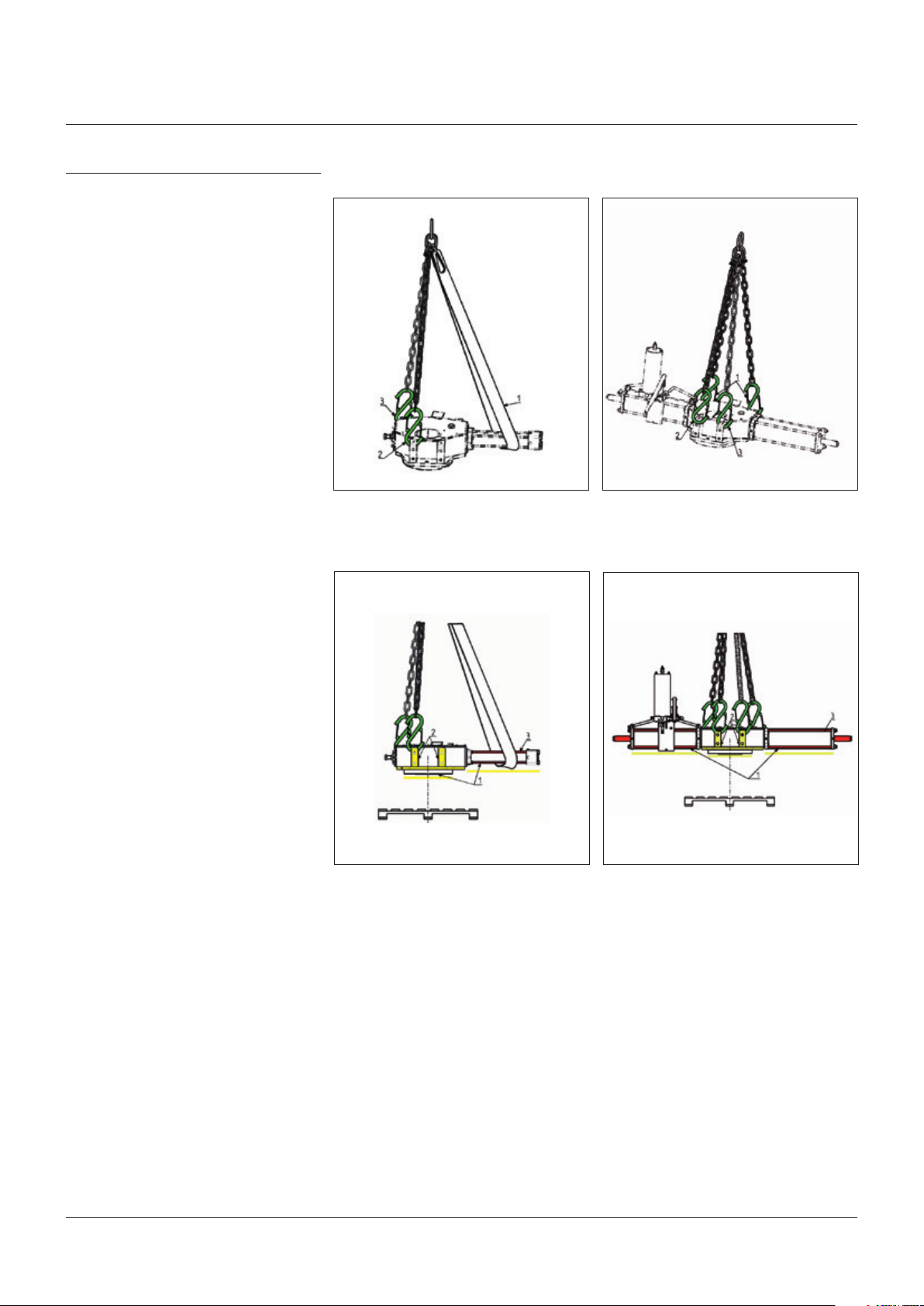
FIGURE 3A, 3B, 3C, 3D
Lifting points for OLGA-H / OLGA-H-MHP / OLGA-H-MSJ actuators
3A 3B
1, 2 = Lifting points (obligatory)
3 = Balancing point
3C 3D
WARNING
The fastening points are appropriate for the lifting
of the actuator alone and not for the valve and
actuator assembly.
Avoid that during the handling, the actuator
passes above the staff.
The actuator should be handled with appropriate
lifting means. The weight of the actuator is
reported on the delivery bill.
1 = Point of support
2 = Supports for lateral positioning
WARNING
3 = Do not lay the actuator on tie rods of cylinder /s and do not lay the actuator on accessories
(manualhand pump, manual jackscrew, pneumatic control group etc.)
3
Page 4
BIFFI OLGA-H HIGH PRESSURE DOUBLE ACTING HYDRAULIC ACTUATOR
INSTALLATION, OPERATION AND MAINTENANCE MANUAL
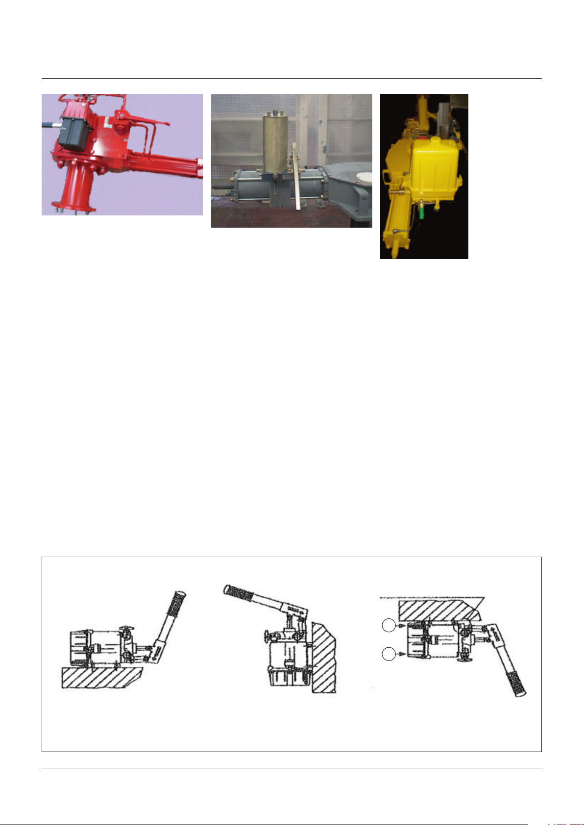
For the transport of OLGA-H actuators with
hydraulic manual hand-pump, when it was
necessary put in horizontal position the tank
of MHP, to avoid leakage on oil level stick,
substitute these with a blind-plug during the
transport (a specific warning label for transport
in horizontal position is attached on the MHP
body); remove the blind plug and restore the
dipstick before operate the actuator with
MHP� Biffi hydraulic manual hand-pump must
be maintained with tank in upper position to
operate the actuator with MHP correctly�
OMFB manual hand-pump should be
transported and used with MHP tank in
horizontal position, but in position 3 of the
following picture (extracted from OMFB
technical documentation) it’s necessary
to change the position of suction pipe and
breather cap:
2.3 Storage
If the actuator needs storage, before
installation follow these steps:
• Place it on a wood surface in order not to
deteriorate the area of valve coupling�
• Make sure that plastic plugs are present
on the hydraulic and electrical connections
(if present)�
• Check that the cover of the control group and
of the limit switch box (if any) are properly
closed�
If the storage is long-term or outdoor:
• Keep the actuator protected from direct
weather conditions�
• Replace plastic plugs of pneumatic and
electrical connections (if any) with metal
plugs that guarantee perfect tightness�
• Coat with oil, grease or protection disc, the
valve coupling area�
• Periodically operate the actuator (section 3�3)�
2.4 Actuator assembly on the valve
2.4.1 Types of assembly
For coupling to the valve, the housing is
provided with a flange with threaded holes
according to Biffi standard tables (SCN6200;
SCN6200-1; SCN6201; SCN6201-1)� The
number, dimensions and diameter of the
holes are made in accordance with ISO 5211,
but for actuator models 0�3 to 6 the holes are
drilled on the centerline in order to allow an
easier assembly of an intermediate flange,
when required� This intermediate flange
(orspool-piece) can be supplied when the valve
flange can not directly match the actuator
flange in its 'standard' configuration� For the
biggest actuator models, the actuator flange
can be machined in accordance with the valve
flange dimensions�
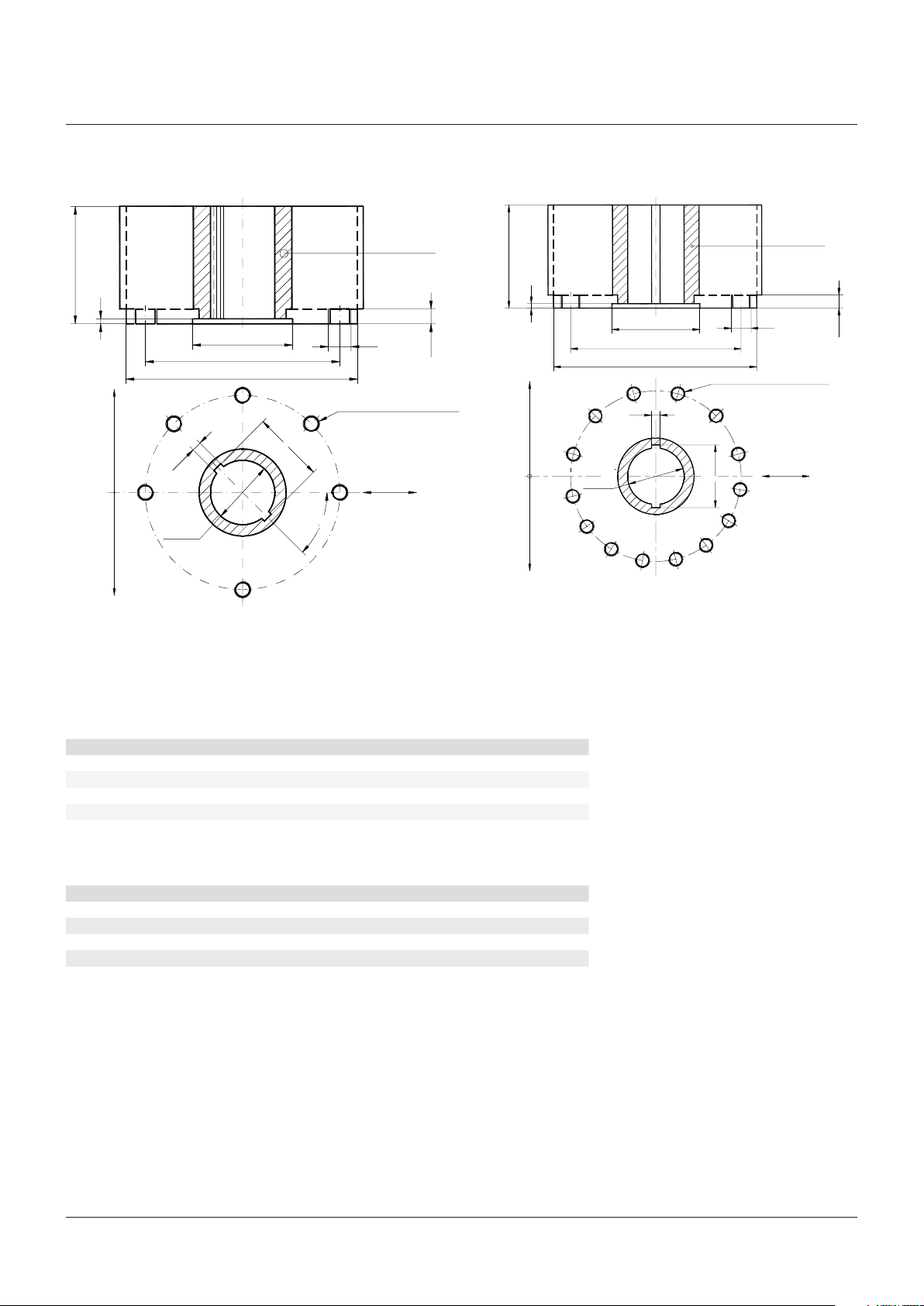
The yoke has bored with keyways for coupling
to the valve stem, the dimensions of which are
according to Biffi standard tables SCN6200and SCN6201 (see next pages)�
FIGURE 4
Fixing positions
POSITION 1
Standard application
POSITION 2
Standard application
Invert the position of the breather cap
A
B
POSITION 3
Change the position of suction pipe from AtoB
and the breather cap to top side
4
Page 5
BIFFI OLGA-H HIGH PRESSURE DOUBLE ACTING HYDRAULIC ACTUATOR
INSTALLATION, OPERATION AND MAINTENANCE MANUAL
FIGURE 5A
Actuator models 0�3 to 6
H max
0
+0�5
h₁
W D10
N�8 holes flange
+0�2
Ø d₅
N�4 holes flange
Top view of the Scotch yoke mechanism
(actuator shown in closed position)
FIGURE 5B
Actuator models 14 to 42
Drive sleeve
H max
0
+0�5
h₁
+0�1
0
+0�1
Ø d₂
±0�2
Ø d₃
Ø d₁ max
+0�4
K
0
+0�1
45
Ø d₄
N� threaded holes
PCD, number and size
according to ISO 5211
(but the holes are on
centerline instead of straddle
the centerline)
h₂
Flow line
º
Ø d₅
Ø d₂
±0�2
Ø d₃
Ø d₁ max
N� threaded holes
PCD, number and size
D10
'W'
+0�2
+0�1
according to ISO 5211
0
+0,4
K
N�16 holes flange N�12 holes flange
Top view of the Scotch yoke mechanism
(actuator shown in closed position)
Drive sleeve
Ø d₄
h₂
Flow line
COUPLING DIMENSIONS MODELS 0.3 TO 0.6 (mm)
Actuator model Ø d₁ Ø d₂ Ø d₃ Ø d₄ N h₁ h₂ H max Ø d₅ W K
0�3 240 93 165 M20 4 5 17 127 70 12 75�6
0�9 310 112 254 M16 8 5 19 150 86 14 96�6
1�5 360 144 298 M20 8 6 19 190 112 18 119
3 430 195 356 M30 8 9 23 200 157 25 167�8
6 520 250 406 M36 8 14 29 260 200 28 212�8
COUPLING DIMENSIONS MODELS 14 TO 42 (mm)
Actuator model Ø d₁ Ø d₂ Ø d₃ Ø d₄ N h₁ h₂ H max Ø d₅ W K
14 580 250 483 M36 12 10 29 340 175 45 195�8
18 680 290 603 M36 16 12 32 350 200 45 220�8
32 780 290 603 M36 16 12 32 400 220 50 242�8
35 780 315 603 M36 16 11 32 400 240 50 242�8
42 840 310 603 M36 16 12 32 400 220 50 242�8
5
Page 6
BIFFI OLGA-H HIGH PRESSURE DOUBLE ACTING HYDRAULIC ACTUATOR
INSTALLATION, OPERATION AND MAINTENANCE MANUAL
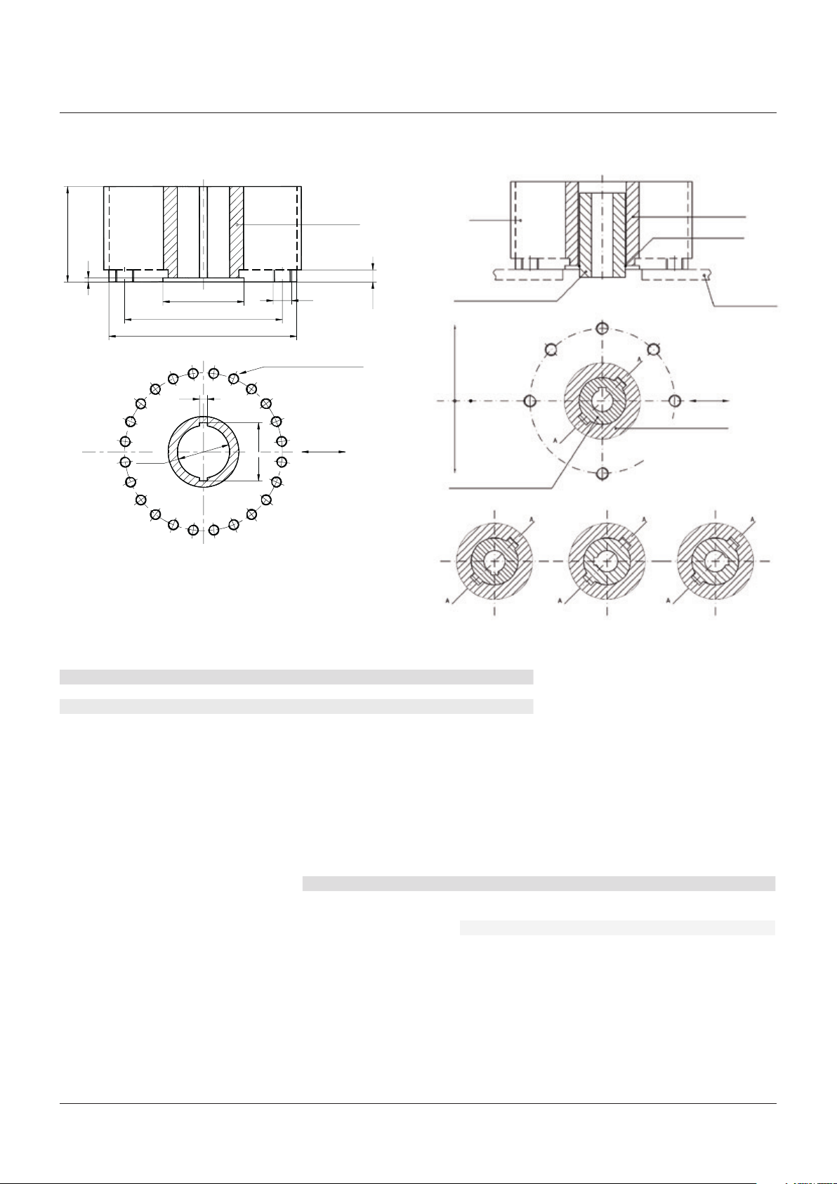
FIGURE 5C
Actuator models 50 and 60
H max
0
+0�5
h₁
'W'
+0�2
+0�1
Ø d₅
+0�1
Ø d₂
±0�2
Ø d₃
Ø d₁ max
D10
FIGURE 5D
Insert bush + intermediate coupling flange
Drive sleeve
0
Ø d₄
N� threaded holes
Flange sizing according to
ISO 5211
h₂
Housing
Insert bush
N�8 holes flange
0
+0,4
K
Flow line
N�4 holes flange
Insert bush
Drive sleeve
Adaptor flange
Standard position 1
Flow line
Drive sleeve
Top view of the Scotch yoke mechanism
(actuator shown in closed position)
Position 2 Position 3 Position 4
COUPLING DIMENSIONS MODELS 50 AND 60 (mm)
Actuator model Ø d₁ Ø d₂ Ø d₃ Ø d₄ N h₁ h₂ H max Ø d₅ W K
50 800 315 698 M36 24 10 32 430 240 56 264�8
60 840 315 698 M36 24 10 32 430 240 56 264�8
If required, for the standard models size
0�3 to 6, Biffi can supply an insert bush with
un-machined bore in accordance with Biffi
standard table SCN6202� On request the insert
bush bore can be machined by Biffi to couple
the valve stem� The particular execution of the
flange and bushing allow the actuator to be
The Biffi insert bush with 2 external keys at 45°
allows to position the keyway for the valve every
90°� Consequently actuator can be mounted
in 4 positions at 90° on top of the valve� For
biggest actuator models, the bore of the yoke
can be machined according to the dimensions
of valve stem�
rotated by 90° in 4 different positions according
to figure 5D�
Rotate insert bush 180° around
vertical-standard position (1)
Position 2 Position 3 Position 4
Rotate insert bush 180° around
axis A-A, from position 2
Rotate insert bush 180° around
axis A-A, from position 1
Insert bush turned upside down
6
Page 7

BIFFI OLGA-H HIGH PRESSURE DOUBLE ACTING HYDRAULIC ACTUATOR
INSTALLATION, OPERATION AND MAINTENANCE MANUAL
2.4.2 Assembly procedure
IMPORTANT
Failure to comply with the following procedures
may impair product warranty.
WARNING
Installation, commissioning and maintenance and
repair works should be carried out by qualified
staff. A non-conforming assembly could be the
source of serious accidents.
For actuator assembly on the valve:
IMPORTANT
Check that the assembly position, as shown
on the documentation, complies with system’s
geometry. Check the consistency of the parts of
actuator-valve coupling.
• Operate the actuator so that it reaches the
position matching valve position (section 3�3)�
• Lubricate valve stem with oil or grease�
• Properly clean and remove grease from
coupling flange surfaces�
• Connect, if supplied separately, the
adjustment insert to valve stem and fasten it
with the special fastening pins�
• Lift the actuator using the special lifting
points (section 2�2)�
• Install the actuator so that valve stem inserts
in the coupling area� This coupling should be
made without forcing�
• Fasten the two parts with the threaded
connections (screws, tie rods, nuts)� If
holes of coupling flanges are not aligned,
adequately operate the actuator if necessary
move the mechanical stops backwards
(section 3�4)�
• Fasten threaded connections� Please refer to
table 1�
2.5 Pneumatic connections
IMPORTANT
Check that the values of pneumatic supply
available are compatible with those reported on
the identification plate of the actuator.
WARNING
The connections should be made by qualified
staff. Use pipes and connections appropriate as
for type, material and dimensions.
Connect the actuator to the hydraulic feed
line with fittings and pipes in accordance to
the plant specifications� They must be sized
correctly in order to guarantee the necessary
oil flow for the operation of the actuator, with
pressure drops not exceeding the maximum
allowable value� The shape of the connecting
piping must not cause excessive stress to
the inlets of the actuator� The piping must be
suitably fastened so as not to cause excessive
stress or loosening of threaded connections,
if the system undergoes strong vibrations�
Every precaution must be taken to ensure
that any solid or liquid contaminants, which
may be present in the hydraulic pipe-work to
the actuator, are removed to avoid possible
damages to the unit or loss of performance�
The inside of the pipes used for the connections
must be well-cleaned before use: wash them
with suitable substances and blow through
them with oil or nitrogen� The ends of the tubes
must be well debarred and cleaned� Once
the connections are completed, operate the
actuator and check that it functions correctly,
that the operation times meet the plant
requirements and that there are no leakages in
the hydraulic connections�
The screwing values in table 1 were calculated
considering the materials ASTM A320 L7 for
screws or tie rods and ASTM A194 gr�2H for
the nuts�
TABLE 1 - NUTS TIGHTENING TORQUE
Threading Tightening torque (Nm)
M8 20
M10 40
M12 70
M14 110
M16 160
M20 320
M22 420
M24 550
M27 800
M30 1100
M33 1400
M36 1700
7
Page 8

BIFFI OLGA-H HIGH PRESSURE DOUBLE ACTING HYDRAULIC ACTUATOR
INSTALLATION, OPERATION AND MAINTENANCE MANUAL
2.6 Electrical connections (if any)
IMPORTANT
Use components appropriate as for type, material
and dimensions. The connections should be made
by qualified staff.
Before carrying out any operation, cut line
power off.
WARNING
Safety provisions:
2006/95/EC: Directive for low voltage equipment.
2004/108/EC: Directive for the electromagnetic
compatibility.
94/9/CE: Directive and safety instructions for use
in hazardous area
Remove plastic plugs from cables entries�
• Screw firmly the cable glands�
• Introduce connection cables�
• Make the connections in compliance
with applicable wiring diagrams on the
documentation supplied�
• Screw the cable gland�
• Replace the plastic plugs of unused entries
with metal plugs�
2.7 Commissioning
WARNING
Check that values of electrical supply to the
control group (if foreseen) are compatible with
those on the plate on the junction box (figure 6).
Installation, commissioning and maintenance and
repair works should be made by qualified staff.
Upon actuator commissioning please carry out
the following checks:
• Check that paint is not be damaged during
transport, if necessary repair the damages to
paint coat�
• Check that the values of hydraulic supply
available in the system are compatible
with those reported on the identification
plate of the actuator (figure 1) and on the
documentation supplied�
• Check that the feed voltage values of the
electric components (solenoid valve coils,
microswitches, pressure switches, etc�)
are compatible with those reported on the
identification plate of the actuator (figure 1)�
• Check that the setting of the components of
the actuator control unit (pressure regulator,
pressure switches, flow control valves, etc�)
meet the plant requirements�
• Carry out all kinds of operations and check
their proper execution (section 3�3)�
• Check the absence of leakages in the
pneumatic connections� If necessary tighten
the nuts of the pipe-fittings�
• Check proper operation of all the due
signalling (valve position, gas supply pressure
etc�)�
• Make a complete functional test in order
to verify all the operations are executed
according to operating schematic diagram
supplied�
FIGURE 6
Junction box on control group (if foreseen)
Ground
8
Page 9
BIFFI OLGA-H HIGH PRESSURE DOUBLE ACTING HYDRAULIC ACTUATOR
INSTALLATION, OPERATION AND MAINTENANCE MANUAL
3 OPERATION AND USE
3.1 Operation description
In the normal operating situation, the double
acting actuator is fed by pressurized gas
which flows into the relevant cylinder chamber
(for example opening)� The cylinder piston
stroke causes the actuator operation and the
consequent valve movement to the operational
position requested (in this case to the “open”
position)�
Upon a demand, the closing chamber the
cylinder is fed by pressurized gas and at the
same time the gas is discharged from the open
chamber into the return line: the actuator
performs the closing operation driven by the
piston movement, and the valve moves from
the open position to the close (safety-related)
position�
For local or remote operations, please refer
to section 3�3�1, 3�3�2, 3�3�3 and 3�3�4 and prior
to technical documentation furnished with
actuators�
Typical schematics for various applications are
following for information only�
The power and control system are suppied on
specific customer demand�
For all the relevant information please refer to the
specific technical documentation supplied with
actuators.
3.2 Residual risks
WARNING
The actuator has parts under pressure.
Use the due caution. Use individual protections
provided for by the laws and provisions in force.
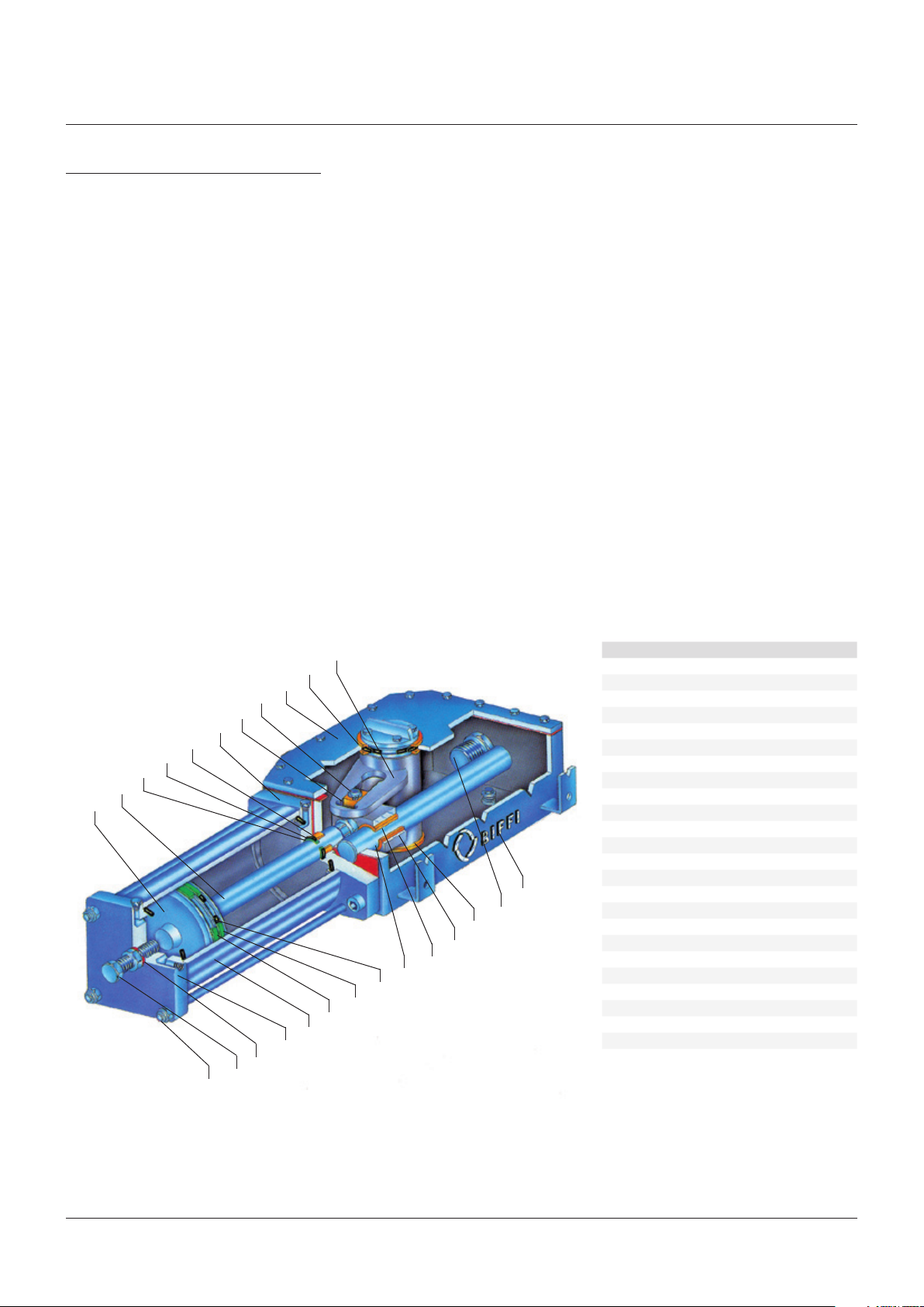
FIGURE 7
16
15
14
13
12
24
11
23
PARTS LIST
2
3
4
5
6
1
10
3
7
8
9
17
18
19
20
21
Item Name
1 Housing
2 Yoke
3 Yoke bushing
4 Cover
5 Guide block pin
6 Sliding block
7 Guide block
8 Guide bar
9 Guide block bushing
10 Travel stop screw
11 Cylinder head flange
12 Piston rod bushing
13 Piston rod O-ring
14 Piston rod seal ring
15 Piston rod
16 Piston
17 Piston O-ring
18 Piston guide sliding ring
19 Piston seal ring
20 Cylinder tube
21 End flange
22 Sealing washer
23 Travel stop screw
24 Tie rod
22
9
Page 10
BIFFI OLGA-H HIGH PRESSURE DOUBLE ACTING HYDRAULIC ACTUATOR
INSTALLATION, OPERATION AND MAINTENANCE MANUAL
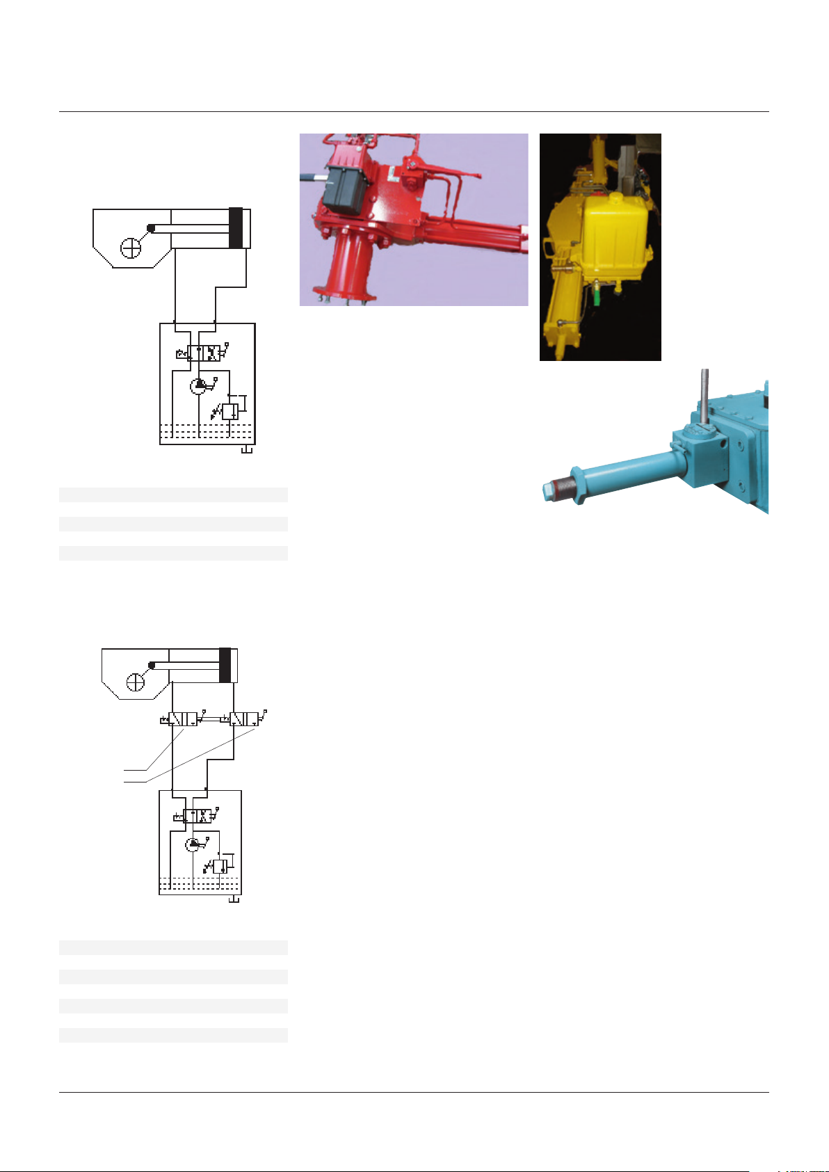
FIGURE 8
OLGA-H with hydraulic manual handpump
1
P
3
1 Scotch yoke mechanism
2 Hydraulic cylinder
3 Hydraulic manual override
D Directional control valve
P Hand pump
R Relief valve
O Oil tank
1
Hydraulic
connections
tothe hydraulic
control panel
(toclose)
(toopen)
3
P
1 Scotch yoke mechanism
2 Hydraulic cylinder
3 Hydraulic manual override
4 Hydraulic manual selector
D Directional control valve
P Hand pump
R Relief valve
O Oil tank
2
3.3 Operations
D
R
(refer to specific document: operating diagram
furnished)
3.3.1 Local manual operation
The OLGA-H actuators can only have the
hydraulic manual override for local operation�
O
The compact hydraulic control unit mounted on
the actuator consist of:
- hand pump
- directional control valve to select “toopen” or
“toclose” actuator operation
- relief valve to prevent the oil pressure
delivered by the hand pump from exceeding
the maximum allowable value
- oil tank
Accessory are available on request, for
instance:
- dual pilot operated check valve
- bladder-type or piston-type accumulator
delivered by the hand pump from exceeding
2
the maximum allowable value� On request the
emergency manual override can be included
in the power pack�
3.3.3 Emergency manual operation by MSJ - MHW
The MSJ jackscrew manual override can be
supplied for OLGA-H actuators from model
0�3 to model 3� The override is mounted on
the left side of the actuator, the jackscrew
end is screwed into the guide block� A bronze
split screw nut is mounted inside the body�
By rotating the engagement lever, the screw
nut is engaged with the jackscrew� When
the screw nut is engaged with the jackscrew
manual operation follows by rotating the body
4
3.3.2 Emergency manual operation by MHP
The OLGA-H actuators can have an emergency
manual override in addition to the local and/
of the screw container by a lever� The manual
jackscrew, on request, could be furnished with
fixed hand-wheel welded on it�
or remote control panel which controls
the oil supplied by a power pack for the
“normal” actuator operation� The emergency
manual override, mounted on the actuator,
consists of a hydraulic manual override and a
D
hydraulic manual selector to choose actuator
“Normaloperation” with oil supply from
R
a power pack, or the “Emergency manual
operation”� Thecompact hydraulic override
O
consist of:
- hand pump
- directional control valve to select the
“toopen” or “toclose” operation by
handpump
- relief valve to prevent the oil pressure
delivered by the hand pump from exceeding
the maximum allowable value
On request the emergency manual override can
be included in the power pack�
10
Page 11
BIFFI OLGA-H HIGH PRESSURE DOUBLE ACTING HYDRAULIC ACTUATOR
INSTALLATION, OPERATION AND MAINTENANCE MANUAL
9A
FIGURE 9A, 9B
Mechanical stops
9B
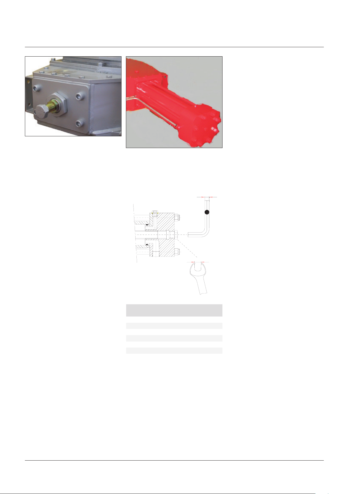
3.4 Calibration of the angular stroke
The angular stroke of the yoke can be adjusted
between 82°÷98° (±4° with respect to the
nominal positions of complete opening and
closing) by means the mechanical stops
screwed into the left side of the housing (open
valve) and into the end flange of the hydraulic
cylinder (closing) (figures 9A, 9B)�
For the adjustment of the mechanical stop on
the end flange of cylinder, follow these steps
(Figure 10):
• Remove with the specific wrench (c2) the plug
of cylinder end-flange�
• Insert a wrench for Allen keys (c1) in the
through hole until reaching the adjustment
pin�
• Turn counter-clockwise to increase the
angular stroke, turn clockwise to decrease it�
• When the adjustment is over tighten the plug
with the wrench c2�
FIGURE 10
Mechanical stop of the cylinder
c1
c2
Hydraulic
cylinder diameter
16 - 28 8 19
28 - 40 8 22
45 - 60 12 27
70 - 175 14 36
200 - 235 22 36
235 - 300 22 36
Wrench c1
(mm)
Wrench c2
(mm)
11
Page 12
BIFFI OLGA-H HIGH PRESSURE DOUBLE ACTING HYDRAULIC ACTUATOR
INSTALLATION, OPERATION AND MAINTENANCE MANUAL
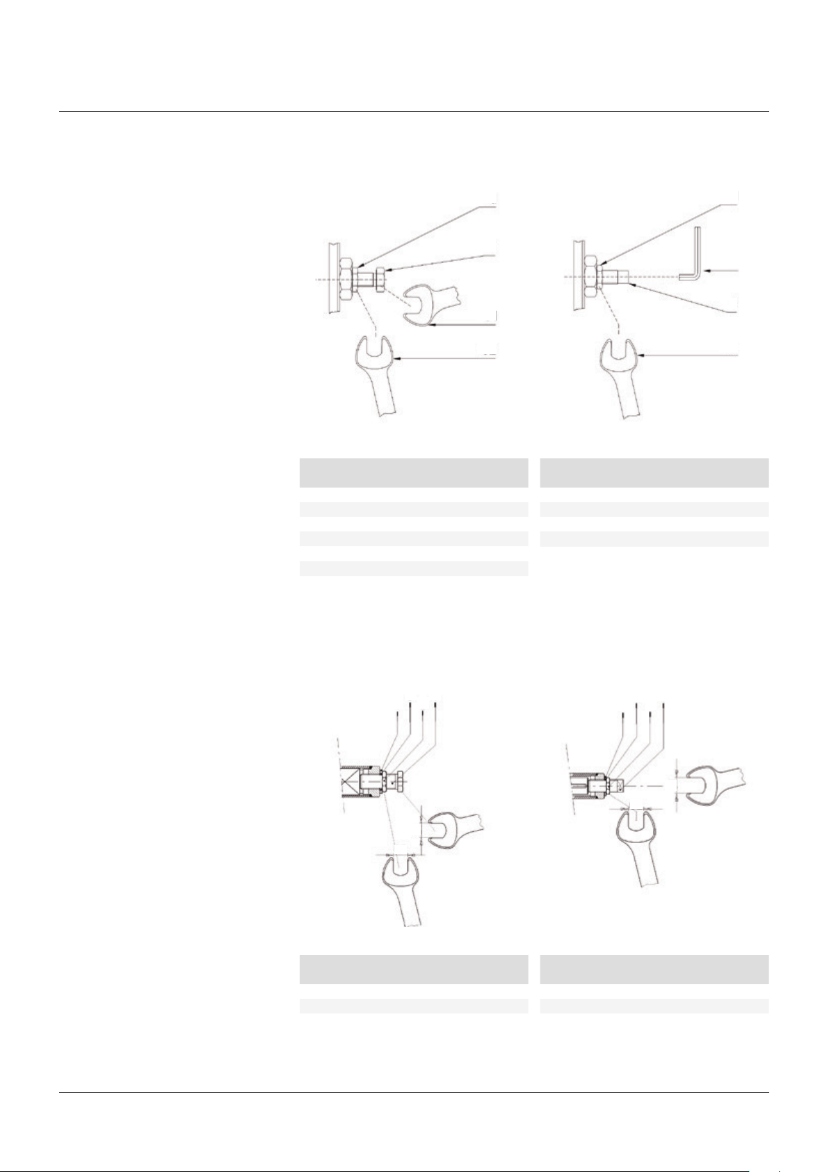
For the adjustment of the mechanical stop
srewed into the left side of housing, follow
these steps (figures 11A and 11B):
• Loosen the locknut (d) with the specific
wrench (c2)�
• Adjust the pin (g)/screw (v) with the adequate
wrench (c1)�
• Turn counter-clockwise to increase the
angular stroke, turn clockwise to decrease it�
• When the adjustment is over tighten the
locknut (d)�
FIGURE 11A, 11B
Mechanical stop on the housing
Wrench c1
Actuator model
0,1 30 30
0,3 30 30
0,9 30 30
1,5 41 41
3 41 41
6 46 46
(mm)
Wrench c2
d
v
c1
c2
(mm)
Wrench c1
Actuator model
14 17 60
18 17 60
32 17 60
50 17 60
(mm)
Wrench c2
(mm)
d
c1
g
c2
For the adjustment of the mechanical stop
screwed on the end flange of manual override
(see section 7�2 figure 33: sectional drawing for
manual jackscrew MSJ)�
FIGURE 12A, 12B
Mechanical stop on the end flange of manual override
1
3
2
4
c1
c2
Wrench c1
(mm)
0,1 34 34
0,3 34 34
0,9 34 34
Wrench c2
(mm)
Actuator size
1,5 24 65
3 24 65
3
4
c2
1
2
Wrench c1
(mm)
c1
Wrench c2
(mm)Actuator size
12
Page 13

BIFFI OLGA-H HIGH PRESSURE DOUBLE ACTING HYDRAULIC ACTUATOR
INSTALLATION, OPERATION AND MAINTENANCE MANUAL
3.5 Calibration of microswitches (with safety instructions for limit switch box)
If the actuator is delivered separately from the
valve, it is necessary to check, and, if required,
to adjust, the settings of the position signalling
microswitches�
IMPORTANT
Operate only the microswitch corresponding to
the direction of operation being carried out, as
clearly reported on the microswitch.
WARNING
If microswitches assembly or limit switch box is
supplied, please refer to the specific technical
documentation.
IMPORTANT
End of stroke microswitches should be operated
before the stop of the stroke of the actuator due
to mechanical stops. Adjust the relative cams
properly.
WARNING
Do not open when energized or when an explosive
atmosphere is present.
WARNING
Electrostatic hazard, clean only with damp cloth.
13
Page 14
BIFFI OLGA-H HIGH PRESSURE DOUBLE ACTING HYDRAULIC ACTUATOR
INSTALLATION, OPERATION AND MAINTENANCE MANUAL
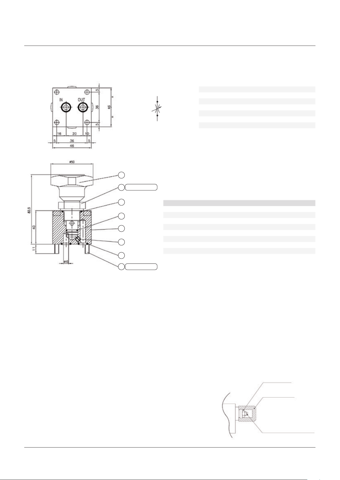
FIGURE 22
Example of operating time adjustment (if foreseen), by flow-regulator valve
(pleaserefertospecific operating diagram, item 526/530 and to specific flow-regulator valve)
TECHNICAL FEATURES
Max� adjusted flow (l/min�) 10
Max� working pressure (bar) 250
Fluid viscosity range (cSt) 5 – 750
Fluid temperature range (˚C) -45 – +60
Mass (kg) 0�70
Hydraulic fluid: mineral oils
Recommended filtration: 19/15 ISO 4466 (25 µ abs�)
Seals in MFQ (fluoro-silicone)
7
Torque 30 Nm
2
3
8
1
4
5
OUT
IN
PARTS LIST
Item Qty Name Material Type or drawing
1 1 Body AISI 316 49�144�031
2 1 Cartridge AISI 316 FT 2267/2-14-hFQSV
3 * 1 O-ring MFQ-70Sh OR 2-116
4 1 Screw A4-70 M5x5 UNI 5923
5 2 O-ring MFQ-70Sh OR 5-612
6 4 Screw A4-70 VCTEI M5x45 UNI 5931
7 1 Handwheel 11S (2011) 29�102�378
8 * 1 OR+2BK MFQ-6Sh+PTFE OR2-013 + 2BK
* included in cartridge item 2
3.6 Calibration of the operating time
(optional- if foreseen)
The calibration of the operation time is made
according to customer requirements and to
technical data-sheet included in technical
documentation� If necessary it’s possible to
modify or reset the operating time through
two flow regulation valves (optional) placed on
inlets of hydraulic cylinder (see figure 22 and
the applicable operating diagram)�
To carry out the adjustment, operate the
hand-wheel (turn clockwise the hand-wheel
to increase the operating time or turn the
hand-wheel counter-clockwise to decrease the
operation time)�
For OLGA-H actuator models with manual
hand pump (MHP), the operating time is
adjustable through two regulation valves placed
on manual hand pump body (see section 7�2
figure 32: sectional drawing for hydraulic
control unit MHP)�
To carry out the adjustment, use a suitable
Allen wrench and follow these steps (figure 23):
Torque 5 Nm
6
• Remove the cap nut�
• Loosen the locknut�
• Screw with a screwdriver the setting screw to
increase the operating time�
• Unscrew with a screwdriver the setting screw
to decrease the operating time�
• After the adjustment is over screw the
locknut and put back in place the cap nut�
FIGURE 23
Flow regulators placed on manual hand pump MHP (optional – if foreseen)�
Lock nut
Acorn nut
Adjustment screw
14
Page 15
BIFFI OLGA-H HIGH PRESSURE DOUBLE ACTING HYDRAULIC ACTUATOR
INSTALLATION, OPERATION AND MAINTENANCE MANUAL
4 OPERATIONAL TESTS AND INSPECTIONS
IMPORTANT
To ensure the guaranteed SIL Level, according
to IEC 61508, the functionality of actuator must
be checked with regular intervals of time, as
described following.
For safety related applications, the following
test operation has to be performed:
1� Full stroke of actuator once a year�
2� Partial stroking test at least every six
months (if applicable, please refer to
operating diagram and operate accordingly)�
3� Visual inspection-checks , according to
section 5�1, but with a frequency of once
a year�
4� Before start up and afterwards every
6months check accumulator pre-charging
pressure (if present: please refer to
technical data-sheet)�
For standard applications please refer to
section 5�1�
5 MAINTENANCE
IMPORTANT
Before carrying out any maintenance operation, it
is necessary to close the hydraulic feed line and
exhaust the pressure from the actuator cylinder
and from the control unit, to ensure safety of
maintenance staff.
WARNING
Installation, commissioning and maintenance
and repair works should be carried out by
qualified staff.
5.1 Periodic maintenance
OLGA-H actuators are designed to operate
long-term in heavy-duty operating conditions,
without maintenance needs�
IMPORTANT
Periodicity and regularity of inspections is
particularly influenced by specific environmental
and working conditions.
WARNING
They can be initially determined experimentally
and then be improved according to actual
maintenance conditions and needs.
Anyway every 2 years of operation the following
is recommended:
• Check that the actuator operates the valve
correctly and with the required operating
times� If the actuator operation is very
infrequent, carry out a few opening and
closing operations with all the existing
controls (remote control, local control,
emergency controls, etc�), if this is allowed by
the conditions of the plant�
FIGURE 24
Level measuring stick
MAXIMUM LEVEL
MINIMUM LEVEL
• Check there are no hydraulic leakages� If
necessary tighten the nuts of the pipe-fittings�
• Check oil level (figure 24) into the hydraulic
control unit (see section 5�1�1)
• Check the actuators did not undergo
accidental damage with oil leakages found on
site (section 4�1�1)�
• Check that improper closing of control-group
cover did not produce the presence of
condensation on it�
• Check the integrity of worn out parts (gaskets,
pads etc�)�
• If there is an oil filter on the actuator, bleed
the condense water accumulated in the cup
by opening the drain cock� Disassemble the
cup periodically and wash it with soap and
water; disassemble the filter: if this is made
up of a sintered cartridge, wash it with nitrate
solvent and blow through with oil� If the filter
is made of cellulose, it must be replaced
when clogged�
5.1.1 Check and restore oil level in the hydraulic
manual override
(refer to section 7�2 figure 26)
- Operate the distributor lever to “closing
manual operation”�
- Move the actuator into his “fail to close”
position�
- Unscrew the dipstick (1)�
- Check that the oil level into the tank (4) is in
correspondence of the “MAX LEVEL” notch of
the dipstick�
- Screw and tighten the dipstick�
- If necessary substitute or add the oil,
proceeding as follows:
• Remove the dipstick (1) from the tank
cover (22)�
• Unscrew the plug (27) and the washer (9) to
drain all the oil�
• If some dirt or/and sludge is found in the oil
drained from the tank, before filling with new
oil in the tank, disassemble the oil tank tube,
by unscrewing the two cap nuts (2), and clean
the internal surfaces of the tank� If necessary
substitute the gaskets (21) of the tank�
• Replace the plug (27) and the washer (9) into
the plate (11) and tighten�
• Pour the new oil into the tank through the
dipstick hole (1) on the cover (22)�
• Replace the dipstick (1)�
• Add oil (refer to table 2) if in the tank the oil
level is BELOW THE MINIMUM (figure 24:
minimum level is in correspondence to the
end of dipstick) until to reach the optimal
(MAXIMUM) oil level�
• Operate the distributor lever to “Remote”
position�
IMPORTANT
For refill use oil of the same brand as previous,
refer to related technical documentation
15
Page 16
BIFFI OLGA-H HIGH PRESSURE DOUBLE ACTING HYDRAULIC ACTUATOR
INSTALLATION, OPERATION AND MAINTENANCE MANUAL
TABLE 2
Features of hydraulic oil suggested for refilling in different working conditions
Standard temperature conditions (-30°C/+85°C)
Producer AGIP
Name ARNICA 22
Viscosity at 40°C 20�9 mm²/s
Viscosity at 100°C 4�73 mm²/s
Viscosity index ASTM 153
Flash point 192°C
Pour point -42°C
Specific weight (at 15°C) 0,857 kg/l
Equivalent oils SHELL TELLUS PLUS 22
CHEVRON HYDRAULIC OIL AW ISO 22
MOBIL DTE22
EXXON UNIVIS N22
EQUIVIS ZS22
BP ENERGOL HLP-HM22
CASTROL DYSPIN AWS22
Low temperature conditions (down to -46°C)
Manufacturer SHELL
Name AEROSHELL FLUID 41
Viscosity at -54°C 2300 cST
Viscosity at -40°C 491 cST
Viscosity at 40°C 14�1 cST
Viscosity at 100°C 5�3 cST
Viscosity index (ISO 2909) >200
Flash point 105°C
Pour point <-60°C
Specific weight 0�87 kg/dm
(Or equivalent)
Low temperature conditions (down to -60°C)
Manufacturer SYNTESIS
Name SYNTRASS-CS 500
Viscosity at -60°C 580 cST
Viscosity at -30°C 39cST
Viscosity at 20°C 5�8 cST
Viscosity at 50°C 2�1 cST
Flash point 152°C
Pour point -68°C
Specific weight 0�897 kg/dm
(Or equivalent)
3
3
FIGURE 25
Replacement of cylinder seals
Stop setting screw cover
A – B
5.2 Extraordinary maintenance
If there are leaks in the hydraulic cylinder,
pneumatic cylinder or a malfunction in
the mechanical components, or in case
of scheduled preventive maintenance, the
actuator must be disassembled and seals must
be replaced with reference to the following
general sectional drawing and adopting the
following procedures�
5.2.1 Replacement of high pressure cylinder seals
(refer to figure 27)
IMPORTANT
Before executing any maintenance operation,
it is necessary to intercept the supply line and
discharge pressure from the cylinder of the
actuator.
Replacement of cylinder seals
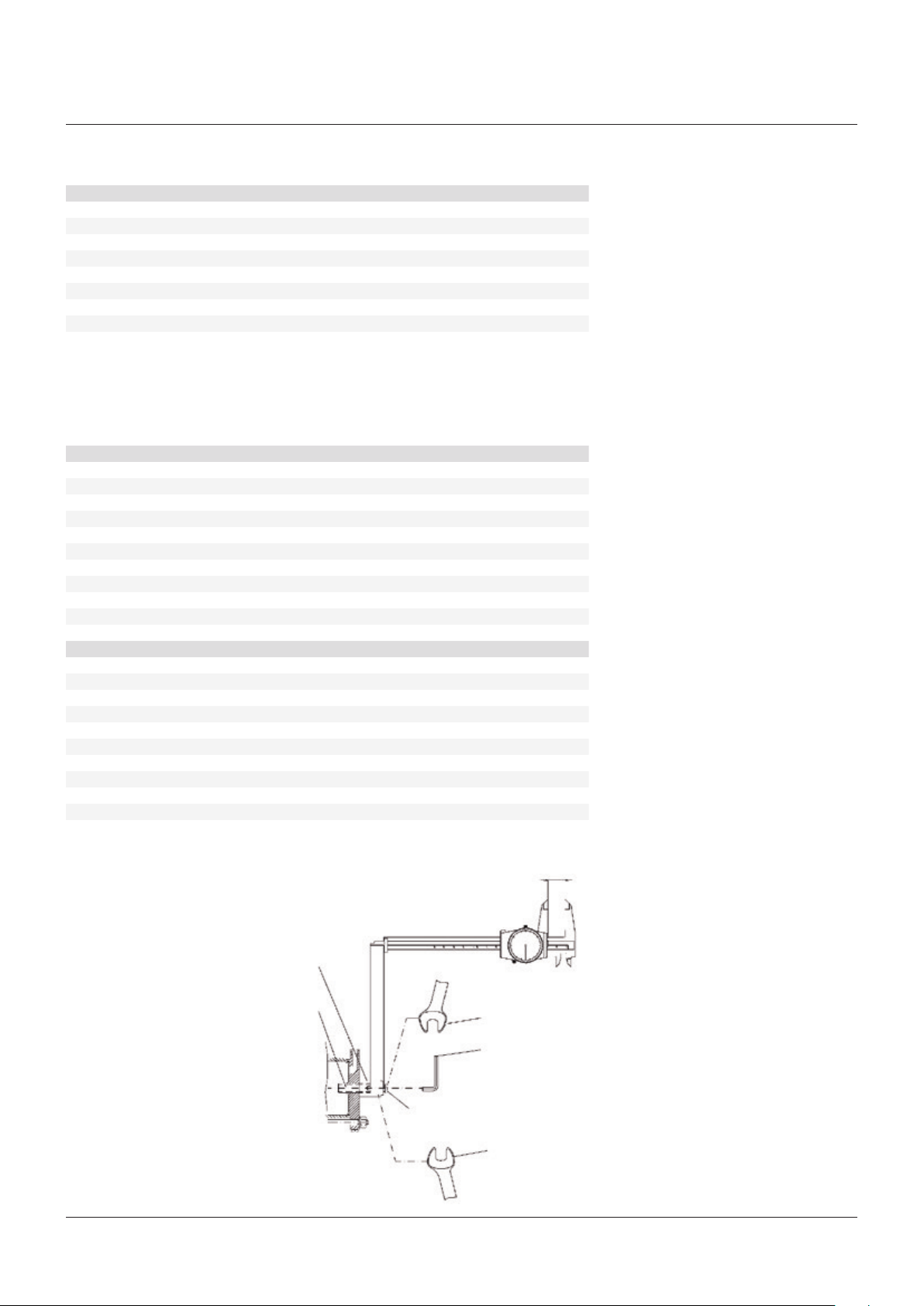
1� Unscrew the plug (27) from the cylinder end
flange�
2� Measure the distance of the stop screw
(23) with reference to the end flange (26)
surface, so as to be able to easily restore
the setting of the actuator mechanical stop,
once the maintenance procedures have
been completed�
3� Unscrew the stop screw (23) by turning it
anticlockwise with an Allen wrench until the
screw is completely with drawn inside the
end flange threaded hole�
4� Unscrew the nuts (28) from the tie rods (19):
they must be gradually unscrewed all at the
same time�
5� Slide off the end flange (26) and the tube
(22)�
6� If the actuator control unit requires the
cylinder chamber head flange side to be
also filled with oil, and the piston rod seal
ring (44) to be replaced, remove the screw
(2) and the cover (1)� Unscrew the piston rod
(18) threaded end from the adaptor bush
(32) of the guide block (14)� Slide off the
piston rod (18) from the head flange (33)�
7� Disassemble the head flange (33) from the
mechanism housing (8) by removing the
screw (17) only if the gasket (39) and (41)
have to be replaced because damaged�
Stop setting screw
c1
c2
Plug
c3
16
Page 17

BIFFI OLGA-H HIGH PRESSURE DOUBLE ACTING HYDRAULIC ACTUATOR
INSTALLATION, OPERATION AND MAINTENANCE MANUAL
Seals replacement
Prior to reassemble check that the actuator
components are in good conditions and clean�
Lubricate all the surfaces of the parts, which
move in contact with other components, by
recommended grease� If the O-ring must be
replaced, remove the existing one from its
groove, clean the groove carefully and lubricate
it with protective oil or grease film� Assemble
the new O-ring into its groove and lubricate it
with a protective oil or grease film�
1� Replace the O-rings (43) of the head flange
(33)�
2� Replace the O-ring (42) of the end flange
(26)�
To replace the piston rod seal rings (44)
proceed as follows:
1� Remove the existing PTFE seal ring (44) with
its O-ring from their groove�
2� Clean the groove carefully and lubricate it
with a protective oil or grease film�
3� Assemble the new O-ring into its groove and
lubricate it with a protective oil or grease
film�
4� Assemble the new PTFE seal ring (44) into
the flange groove, inside its rubber O-ring,
by bending it: take care that the bending
radius is as large as possible to avoid
damaged the seal� Then enlarge the seal
ring with your fingers so as to restore its
round shape: pay attention not to utilize any
tools, which can damage the seal ring�
To replace the piston seal ring (46) proceed as
follows:
1� Remove the existing PTFE seal ring (46) with
its O-ring from their groove�
2� Clean the groove carefully and lubricate it
with a protective oil or grease film�
3� Assemble the new O-ring into its groove and
lubricate it with a protective oil or grease
film�
4� Assemble the new PTFE seal ring (46) on
its rubber O-ring by introducing one side of
it into the groove, then enlarge it with your
fingers so as to fit it into the groove: take
care to enlarge it uniformly without any
tools which could possibly damage it� The
elastic memory of the kind of PTFE the seal
ring is made of allows the ring to shrink
back to its previous dimension after a short
time�
the threaded end of the piston rod (18) and
the threaded hole of the adaptor bush (32)
of guide block (14)� Spread some sealant
LOCTITE 452, or equivalent, on the rod
threaded end and tighten�
4� Carefully clean the inside of the tube
(22) and check that the entire surface,
particularly that of the bevels, is not
damaged� Lubricate with a protective oil
film the tube internal surface and the bevels
at the ends� Slide the tube onto the piston
taking care not to damaged the PTFE seal
ring (46): the tube bevel has to smoothly
compress the seal ring; take care also not
to damage the head flange O-ring (43)�
5� Assemble the end flange by centring it on
the inside diameter of the tube, taking care
not to damage the O-ring (43)�
6� Assemble the nuts (28) onto the tie rods
(19)� Tighten the nuts to the recommended
torque, alternating between opposite
corners�
7� Restore a generous coating of grease on
the contact surfaces of the yoke (11) and the
bushing (35), on the yoke grooves, on the
sliding blocks (5), on guide bar (9)�
8� Assemble the new gasket (10) after cleaning
the surfaces of the housing (8) and cover (1)
9� Lubricate with protective oil or grease the
O-ring (34)�
10� Assemble the cover (1) and the screws (2)�
Tighten the screws to the recommended
torque�
11� Screw the stop screw (21) by turning it
clockwise with an Allen wrench until it
reaches its original position (the same
distance with reference to the end flange
surface)�
12� Screw the plug (27) into the cylinder end
flange�
IMPORTANT
AFTER MAINTENANCE OPERATIONS CARRY OUT
A FEW ACTUATOR OPERATIONS TO CHECK THAT
ITS MOVEMENT IS REGULAR AND THAT THERE
IS NO AIR LEAKAGE THROUGH THE SEALS.
Reassemble
1� Assemble the new gasket (39-41) after
cleaning the surfaces of housing (8), the
flange (40) and head flange (33), which are in
contact�
2� Assemble the head flange (33), replace the
washers if damaged, tighten the screws (17)
to the recommended torque�
3� Lubricate the piston rod (18) surface, with a
protective oil or grease film and introduce
it into the head flange hole, taking care not
to damage the O-ring (43)� Carefully clean
17
Page 18
BIFFI OLGA-H HIGH PRESSURE DOUBLE ACTING HYDRAULIC ACTUATOR
INSTALLATION, OPERATION AND MAINTENANCE MANUAL
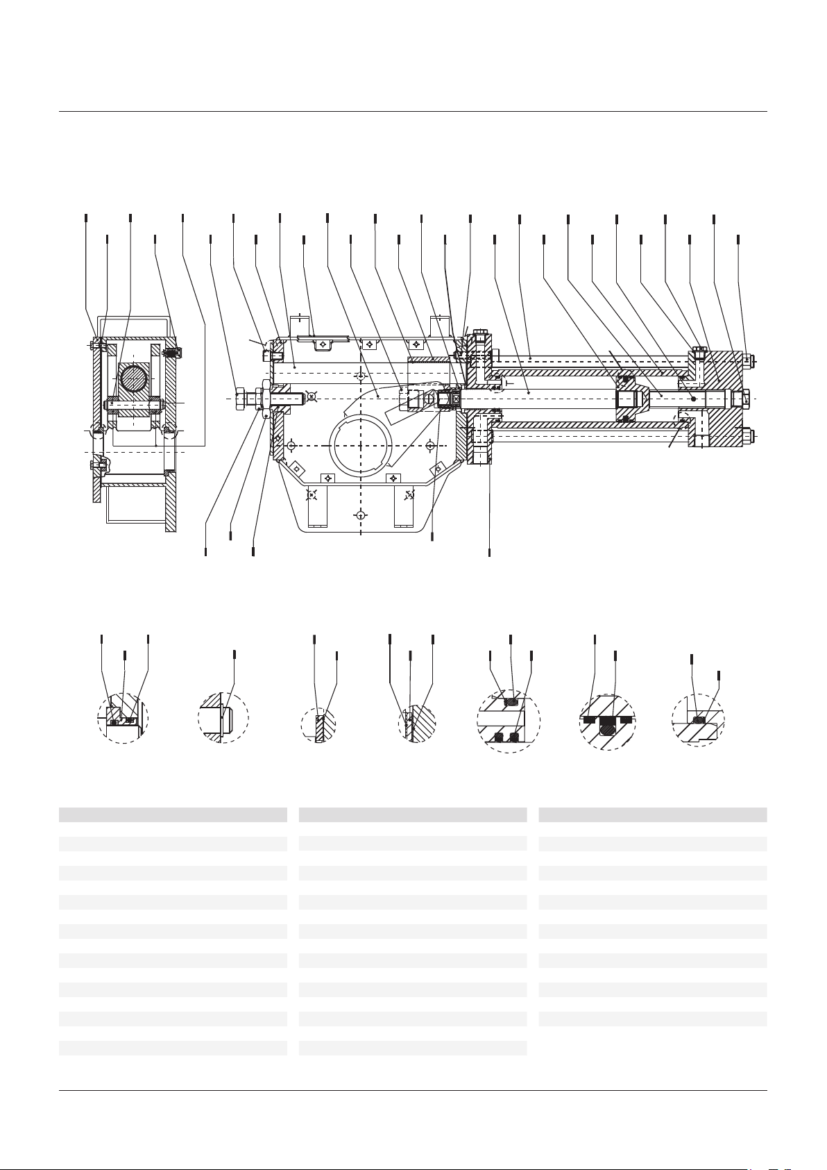
FIGURE 26
OLGA-H double acting hydraulic actuator with manual override
22
23
F
F
21
33
33
18
1917
E
E
1 3 5 7 9 11 13 15 17 19 21 23 25 27
5 931 11
2 4 6 8 10 12 14 16 18 20 22 24 26 28
B
B
A
A
A
A
29
29
7
6
C
C
30
30
31
31
13
12
15
32
32
16 201084
D
D
142
24
G
25
26
G
27
28
34 34
34
35 36
35
A
PARTS LIST
Item Description
1 Cover
2 Screw
3 Guide block pin
4 Vent valve
5 Sliding block
6 Travel stop screw
7 Screw
8 Housing
9 Guide bar
10 Cover gasket
11 Yoke
12 Plug
13 Bushing
14 Guide block
15 Washer
16 Piston rod bushing
45
46
464442
FED GBA
43
43
42
43
4440
33 Head flange
34 O-ring
35 Yoke bushing
36 Retainer ring
37 Flange
38 Gasket
39 Gasket
40 Flange
41 Gasket
42 Back-up ring
43 O-ring
44 Piston rod seal ring
45 Guiding sliding ring for piston
46 Piston seal ring
37 394041 43 45
36
B C D E F G
38
38
C
Item Description Item Description
17 Screw
18 Piston rod
19 Tie rod
20 Piston
21 Stop setting screw
22 Cylinder tube
23 Friction bar
24 Washer
25 Plug
26 End flange
27 Plug
28 Nut
29 Nut
30 Nut
31 Stopper bush
32 Adaptor bush
3934 37
41
42
42
18
Page 19

BIFFI OLGA-H HIGH PRESSURE DOUBLE ACTING HYDRAULIC ACTUATOR
INSTALLATION, OPERATION AND MAINTENANCE MANUAL
Replacement of seals for actuators with Biffi
manual hand-pump (see figure 27)
If there are leaks in the hydraulic cylinder or a
malfunction in the mechanical components, or
in case of scheduled preventive maintenance,
the actuator must be disassembled and
seals must be replaced with reference to the
sectional drawing and adopting the following
procedures:
1� Remove the nuts (item 16) and the washers
(item 15) from the tie rods (item 10) at the
end flange (item 13) side�
2� Slide off the end flange and the tube
(item12)�
3� Remove the screws (item 2-fig� 26) and the
cover (item 1-fig� 26)�
4� Unscrew the piston rod (item 6) threaded
end from the adaptor bush (item 32-fig� 26)
of guide block (item 14-fig� 26)�
5� Slide off the piston rod from the head flange
(item 2)�
6� Disassemble the head flange from the
mechanism housing (item 8-fig� 26) by
removing the screws (item 7- fig� 26) only
if the gasket (item 39-fig� 26) has to be
replaced because damaged�
Seals replacement
Prior to reassemble check that the actuator
components are in good conditions and clean�
Lubricate all the surfaces of the parts, which
move in contact with other components, by
recommended grease� If the O-ring must be
replaced, remove the existing one from its
groove, clean the groove carefully and lubricate
it with protective oil or grease film� Assemble
the new O-ring into its groove and lubricate it
with a protective oil or grease film�
1� Replace the O-rings (3) of the head flange
(2)�
2� Replace the O-ring (3) of the end flange (13)�
For replacement of piston rod seal ring (4) and
of the O-ring (5) proceed as follows:
1� Remove the existing PTFE seal ring (4) and
the O-ring (5) from their groove�
2� Clean the groove carefully and lubricate it
with a protective oil or grease film�
3� Assemble the new O-ring into its groove and
lubricate it with a protective oil or grease
film�
4� Assemble the new PTFE seal ring (4) into
the flange groove, on the rubber O-ring (5),
by bending it: take care that the bending
radius is as large as possible to avoid
damaged the seal� Then enlarge the seal
ring with your fingers so as to restore its
round shape: pay attention not to utilize any
tools, which can damage the seal ring�
To replace the piston dual-seal ring (9) proceed
as follows :
1� Remove the existing dual-seal ring (9) from
its groove�
2� Clean the groove carefully and lubricate it
with a protective oil or grease film�
3� Assemble the new dual-seal ring (9) by
introducing one side of it into the groove
and then enlarge it with your fingers so as
to introduce it into the groove: take care
to enlarge it uniformly without any tools
which could possibly damage it� The elastic
memory of the kind of PTFE type the seal
ring is made of allows the ring to shrink
back to its previous dimension after a short
time�
4� If the O-ring (17) has to be replaced,
measure the protrusion of the stop screw
(11) with reference to the end flange (13)
surface, so as to be able to easily restore
the setting of the actuator mechanical
stop in the open valve position, once
the maintenance procedures have been
completed�
5� Loosen the protection cover (14) and
unscrew the stop screw (11) until it is
removed�
6� Replace the O-ring (17) from the stop screw
cover (14)�
7� Screw the stop screw into the threaded hole
of the end flange until it reaches its original
position (the same protrusion with reference
to the flange surface)�
8� Tighten the protection cover (14)�
Reassemble
1� Assemble the new gasket (item 39-fig�26)
after cleaning the surfaces of housing
(item8-fig� 26) and head flange (item 2)
which are in contact�
2� Assemble the head flange and tighten the
screws (item 7- fig� 26) to the recommended
torque�
3� Clean and lubricate the piston rod (item 6)
surface, particularly that of the bevel, with
a protective oil or grease film and introduce
it into the head flange hole, taking care not
to damage the PTFE seal ring (item 4): the
piston rod bevel has to enlarge smoothly the
seal ring�
4� Carefully clean the threaded end of the
piston rod and the threaded hole of the
adaptor bush (item 32-fig� 26) of guide block
(item 14-fig� 26)� Spread some sealant
LOCTITE 452, or equivalent, on the rod
threaded end and screw into the adaptor
bush threaded hole and tighten�
5� Carefully clean the inside of the tube
(item12) and check that the entire surface,
particularly that of the bevels, is not
damaged� Lubricate with protective oil or
a grease film the tube inside surface and
the bevels at the ends� Slide the tube onto
the piston taking cares not to damaged the
dual-seal ring (item 9): the tube bevel has to
smoothly compress the seal ring�
6� Take care also not to damage the head
flange O-ring (item 3)�
7� Assemble the end flange (item 13) by
centring it on the inside diameter of the
tube, taking cares not to damage the O-ring
(item 3)�
8� Assemble the washers (item 15) and the
nuts (item 16) onto the tie rods (item 10)�
Tighten the nuts to the recommended
torque, alternating between opposite
corners�
9� Restore a generous coating of grease on
the contact surfaces of the yoke (item 11fig� 26) and the bushings (item 13-fig� 26),
on the yoke grooves, on the sliding blocks
(item5-fig� 26), on guide bar (item 9-fig� 26)�
10� Assemble the new gasket (item 39-fig� 26)
after cleaning the surfaces of the housing
(item 8-fig� 26) and cover (item 1-fig� 26)
11� Lubricate with protective oil or grease the
O-ring (item 34-fig� 26)�
12� Assemble the cover (item 1-fig� 26) and the
screws (item 2-fig� 26)� Tighten the screws
to the recommended torque�
IMPORTANT
AFTER MAINTENANCE OPERATIONS CARRY OUT
A FEW ACTUATOR OPERATIONS TO CHECK THAT
ITS MOVEMENT IS REGULAR AND THAT THERE
IS NO AIR LEAKAGE THROUGH THE SEALS.
19
Page 20
BIFFI OLGA-H HIGH PRESSURE DOUBLE ACTING HYDRAULIC ACTUATOR
INSTALLATION, OPERATION AND MAINTENANCE MANUAL
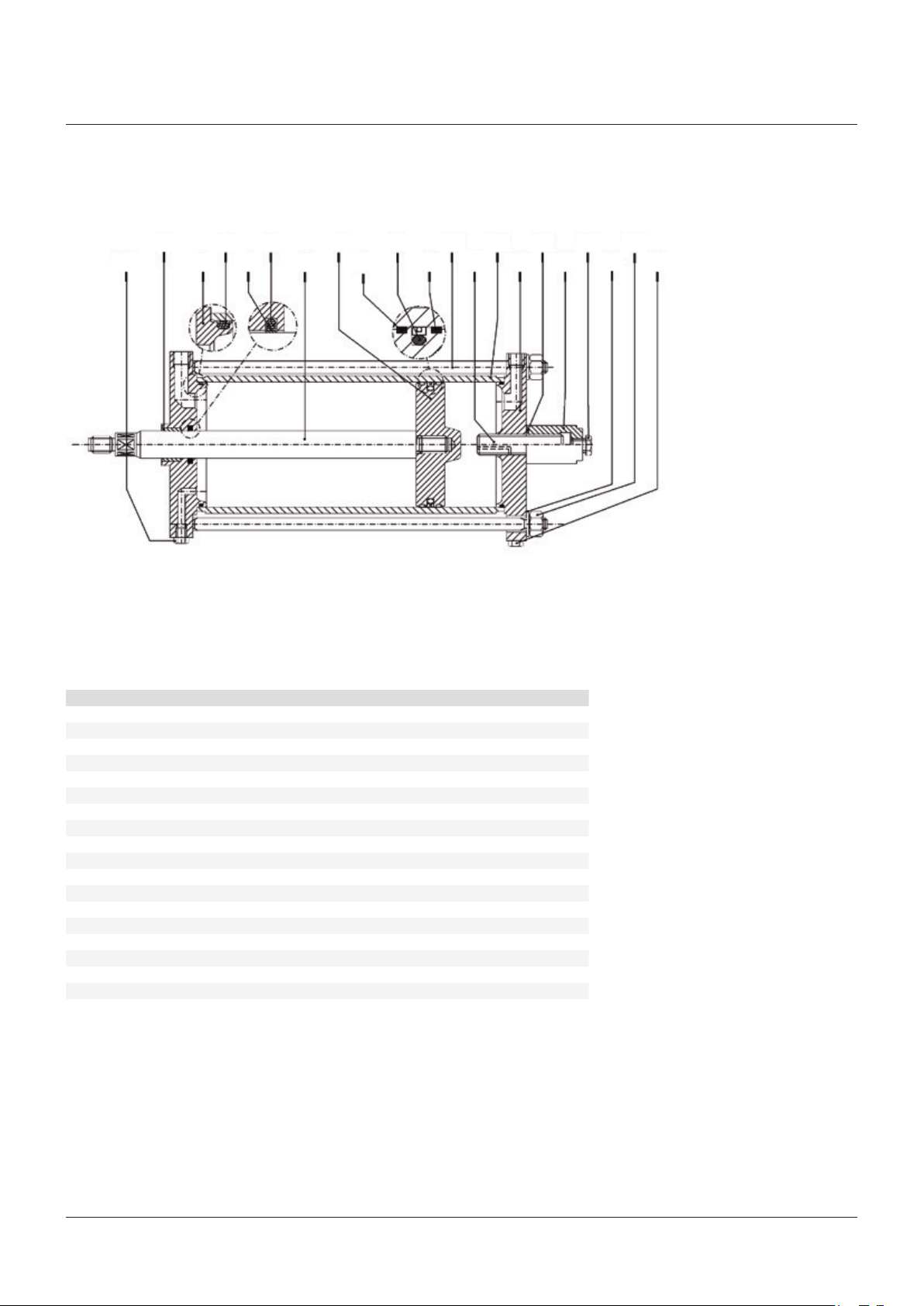
FIGURE 27
Hydraulic cylinder for Biffi manual hand pump
1917
7
18 15
84
8 19
11
125 931
136
142
20
1610
PARTS LIST
Item Q.ty Description Material
1 1 Piston rod bushing Steel + bronze + PTFE
2 1 Head flange Carbon steel
3* 2 O-ring NBR
4* 1 Piston rod seal ring PTFE + graphite
5* 1 O-ring NBR
6 1 Piston rod Alloy steel
7 1 Piston Nickel plated carbon steel
8* 2 Guide sliding ring for piston PTFE + graphite
9* 1 Piston seal ring PTFE + NBR
10 4 Tie rod Alloy steel - ASTM A320 gr� L7
11 1 Stop setting screw Alloy steel
12 1 Cylinder tube Nickel plated carbon steel
13 1 End flange Carbon steel
14 1 Stop setting screw cover Carbon steel
15 4 Spring washer Carbon steel
16 4 Nut Carbon steel - ASTM A194 gr� 7
17* 1 O-ring NBR
18 6 Plug Carbon steel
19 1 Plug Carbon steel
* Recommended spare parts
20
Page 21

BIFFI OLGA-H HIGH PRESSURE DOUBLE ACTING HYDRAULIC ACTUATOR
INSTALLATION, OPERATION AND MAINTENANCE MANUAL
5.3 Lubrication of mechanism
For normal duty the scotch yoke mechanism
of the actuator is lubricated “for life”� In case
of high load and high frequency of operation
it may be necessary to periodically restore
lubrication: it is advisable to apply a generous
coating of grease on the contact surfaces of the
yoke and bushings, on the yoke link grooves, on
the sliding blocks, on the guide bar�
For this operation it is necessary to
disassemble the mechanism cover� In larger
actuators the lubrication can be performed
through the inspection holes of the cover after
removing the plugs�
The following grease is used by Biffi for
standard working temperature and suggested
for re-lubrication, see table�
5.4 Dismantling and demolition
Before starting the disassembly a large area
should be created around the actuator so to
allow any kind of movement without problems
of further risks created by work-site�
WARNING
Before disassembling the actuator it is necessary
to close the pneumatic feed line and discharge
pressure from the cylinder of the actuator, from
the control unit and from the accumulator tank,
if present.
AGIP MU/EP/2 AEROSHELL GREASE 7 or equivalent
To be used in standard temperature conditions
(-30°C/+85°C)
NLGI consistency: 2
Worked penetration: 280 dmm
ASTM dropping point: 185°C
Base oil viscosity at 40°C: 160 mm²/s
ISO classification: L-X-BCHB 2
DIN 51 825: KP2K – 20
Equivalent to:
ESSO BEACON EP2
BP GREASE LTX2
SHELL ALVANIA GREASE R2
ARAL ARALUB HL2
CHEVRON DURALITH GREASE EP2
CHEVRON SPHEEROL AP2
TEXACO MULTIFAK EP2
MOBILPLEX 47
PETROMIN GREASE EP2
To be used in low temperature conditions
(-60°C/+65°C)
Color: Buff
Physical state: Semi-solid at ambient temperature
Odor: Slight
Density: 966 kg/m³ at 15°C
Flash point: >215°C (COC)(based on synthetic oil)
Dropping point: 260°C (ASTM D-566)
Product code: 001A0065
Infosafe no�: ACISO GB/eng/C
If actuator is still mounted onto the valve,
loosen the threaded connections between valve
and actuator (screws, tie rods, nuts)�
Lift the actuator using the proper lifting points
(see section 2�2)�
If the actuator needs storage, before
demolition, see section 2�3�
IMPORTANT
The demolition of the actuator both concerning
any electrical and mechanical parts should be
made by specialized staff.
Separate the parts composing the actuator
according to their nature (ex� metallic, and
plastic materials, fluids etc�) and send them
to differentiated waste collection sites, as
provided for by the laws and provisions in force�
21
Page 22

BIFFI OLGA-H HIGH PRESSURE DOUBLE ACTING HYDRAULIC ACTUATOR
INSTALLATION, OPERATION AND MAINTENANCE MANUAL
6 TROUBLESHOOTING
6.1 Failure or breakdown research
Event Possible cause Remedy
Actuator does not work 1� Lack of power supply 1� Restore it
2� Lack of pneumatic supply 2� Open line interception valve
3� Blocked valve 3� Repair or replace
4� Wrong position of the distributor of the manual hydraulic group 4� Restore correct position
5� Failure of the control group 5� Call Biffi Customer Service
6� Low supply pressure 6� Restore (section 1�4)
Actuator too slow 1� Low supply pressure 1� Restore (section 1�4)
2� Wrong calibration of flow regulator valves 2� Restore (section 3�6)
3� Wear of the valve 3� Replace
Actuator too fast 1� High supply pressure 1� Restore (section 1�4)
2� Wrong calibration of flow regulator valves 2� Restore (section 3�6)
Leakages on hydraulic or
pneumatic circuits
Incorrect position of the valve 1� Wrong adjustment of mechanical stops 1� Restore (section 3�4)
Hydraulic manual pump does
not work
1� Deterioration and/or damage to gaskets 1� Call Biffi Customer Service
2� Wrong warning of microswitches 2� Restore (section 3�5)
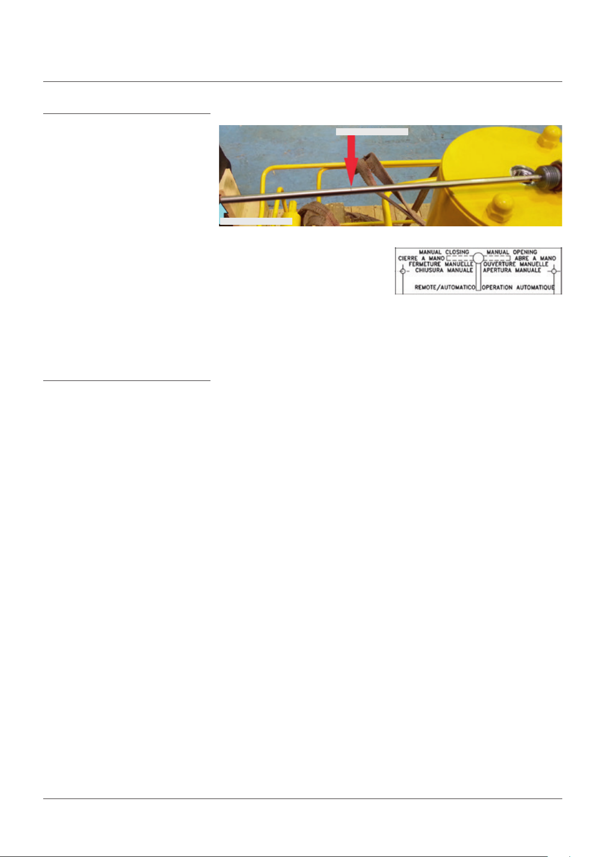
1� Handle positioned on remote control 1� Re-position the operation indication handle to manual
2� Leakages on the check valve of the hydraulic control group 2� Call Biffi Customer Service
7 LAYOUTS
7.1 Spare parts order
For spare parts order to the relevant Biffi
office please make reference to Biffi order
confirmation concerning all the supply, and
serial number of the actuator (section 1�2) for
any specific spare part for a specific actuator
model�
Please send every spare-parts request to:
Biffi Italia S�r�l�
Servizio Assistenza Tecnica Clienti
E-mail: spareservice@biffi�it
Please specify:
1� Actuator model
2� Biffi acknowledgement
3� Spare parts code
4� Quantity
5� Transport condition
6� Involved people
22
Page 23
BIFFI OLGA-H HIGH PRESSURE DOUBLE ACTING HYDRAULIC ACTUATOR
INSTALLATION, OPERATION AND MAINTENANCE MANUAL
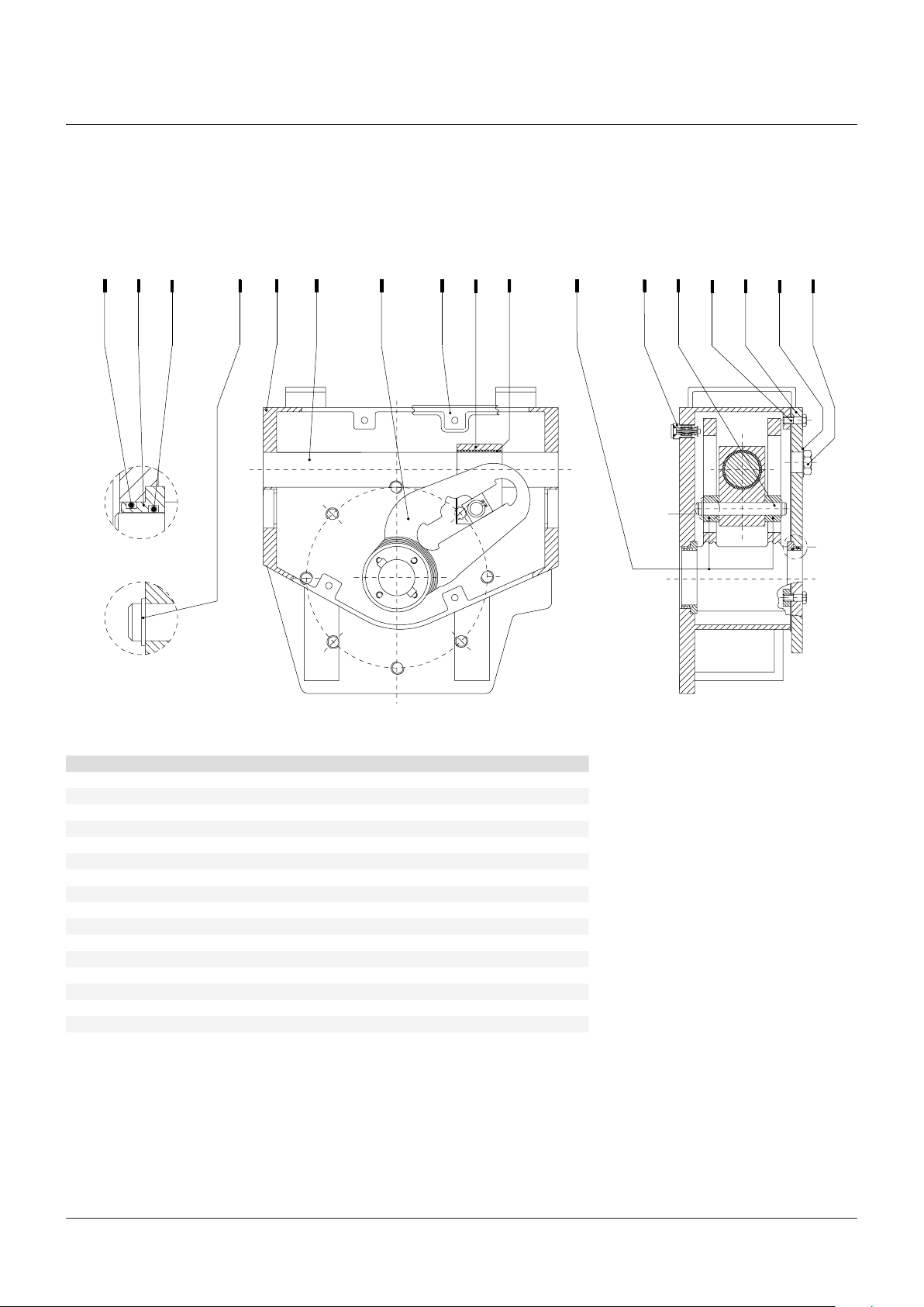
7.2 Parts list for maintenance and replacing procedure
FIGURE 28
Scotch yoke mechanism
1
2
1
3
5 6 7
4
9 10 11
8
15
14
13
12
16
A
B
PARTS LIST
Item Q.ty Description Material
1* 4 O-ring NBR
2 2 Yoke bushing Bronze
3 2 Retainer ring Stainless steel
4 1 Housing Carbon steel
5 1 Guide bar Alloy steel
6 1 Yoke Carbon steel
7* 1 Cover gasket Fiber
8 1 Guide block Carbon steel
9 1 Bushing Steel + bronze + PTFE
10 2 Sliding block Bronze
11* 1 Vent valve Stainless steel
12 12 Screw Carbon steel
13 1 Cover Carbon steel
14 1 Guide block pin Alloy steel
15 1 Washer Copper
16 1 Inspection plug Carbon steel
* Recommended spare parts
B
A
23
Page 24
BIFFI OLGA-H HIGH PRESSURE DOUBLE ACTING HYDRAULIC ACTUATOR
INSTALLATION, OPERATION AND MAINTENANCE MANUAL
FIGURE 29
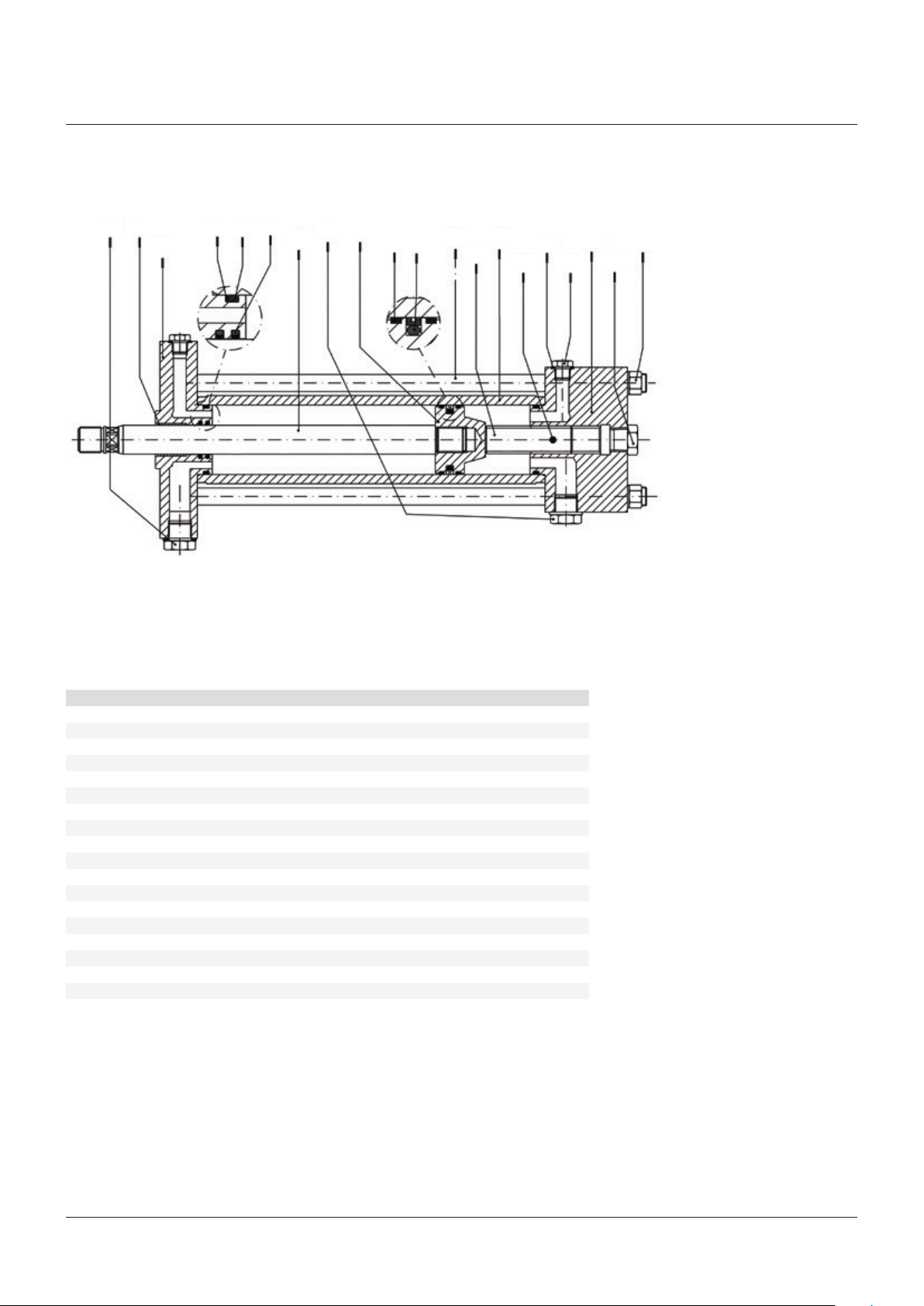
Hydraulic cylinder
19
5931
2
4
14
7
8
10
11
12
16
136
1718
15
14
PARTS LIST
Item Q.ty Description Material
1 1 Piston rod bushing Steel + bronze + PTFE
2 1 Head flange Nickel plated carbon steel
3* 2 O-ring NBR
4* 1 Piston rod seal ring PTFE + graphite + NBR
5* 1 Back-up ring NBR
6 1 Piston rod Chomium plated alloy steel
7 1 Piston Carbon steel
8* 2 Guide sliding ring for piston PTFE + graphite
9* 1 Piston seal ring PTFE + graphite + NBR
10 4 Tie rod Carbon steel - ASTM A320 gr� L7
11 1 Stop setting screw Carbon steel
12 1 Cylinder tube Nickel plated carbon steel
13 1 End flange Nickel plated carbon steel
14 1 Plug Carbon steel
15 4 Nut Carbon steel - ASTM A194 gr� 7
16* 4 Washer
17 1 Plug Stainless steel
18 6 Friction bar Nylon
19 1 Plug Stainless steel
* Recommended spare parts
24
Page 25
BIFFI OLGA-H HIGH PRESSURE DOUBLE ACTING HYDRAULIC ACTUATOR
INSTALLATION, OPERATION AND MAINTENANCE MANUAL
FIGURE 30
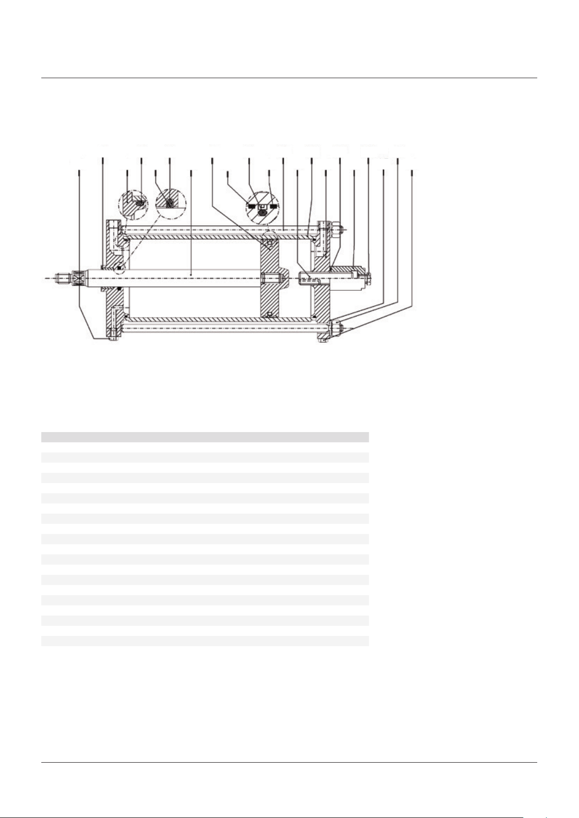
Hydraulic cylinder for manual hand pump (optional)
1917
7
18 15
84
8 19
11
125 931
136
142
20
1610
PARTS LIST
Item Q.ty Description Material
1 1 Piston rod bushing Steel + bronze + PTFE
2 1 Head flange Carbon steel
3* 2 O-ring NBR
4* 1 Piston rod seal ring PTFE + graphite
5* 1 O-ring NBR
6 1 Piston rod Alloy steel
7 1 Piston Nickel plated carbon steel
8* 2 Guide sliding ring for piston PTFE + graphite
9* 1 Piston seal ring PTFE + NBR
10 4 Tie rod Alloy steel - ASTM A320 gr� L7
11 1 Stop setting screw Alloy steel
12 1 Cylinder tube Nickel plated carbon steel
13 1 End flange Carbon steel
14 1 Stop setting screw cover Carbon steel
15 4 Spring washer Carbon steel
16 4 Nut Carbon steel - ASTM A194 gr� 7
17* 1 O-ring NBR
18 6 Plug Carbon steel
19 1 Plug Carbon steel
20 1 Plug Carbon steel
* Recommended spare parts
25
Page 26
BIFFI OLGA-H HIGH PRESSURE DOUBLE ACTING HYDRAULIC ACTUATOR
INSTALLATION, OPERATION AND MAINTENANCE MANUAL
FIGURE 31
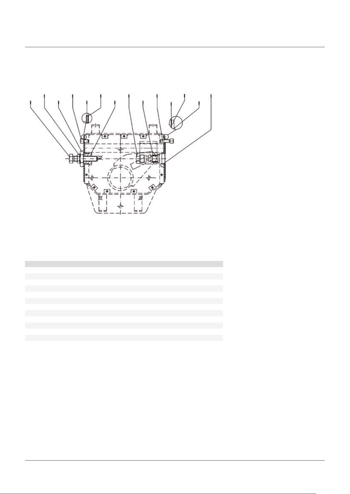
Assembly kit
2
6 12
5 931
7
1084
PARTS LIST
Item Q.ty Description Material
1 1 Screw Alloy steel
2 1 Nut Carbon steel
3 1 Nut Carbon steel
4 4 Screw Alloy steel
5 2 Flange Carbon steel
6* 2 Gasket Fiber
7 1 Stopper bush Alloy steel
8 1 Plug Alloy steel
9 1 Adaptor bush Alloy steel
10 4 Screw Alloy steel
11* 1 Gasket Fiber
12 1 Washer Alloy steel
* Recommended spare parts
5
6
11
26
Page 27
BIFFI OLGA-H HIGH PRESSURE DOUBLE ACTING HYDRAULIC ACTUATOR
INSTALLATION, OPERATION AND MAINTENANCE MANUAL
FIGURE 32
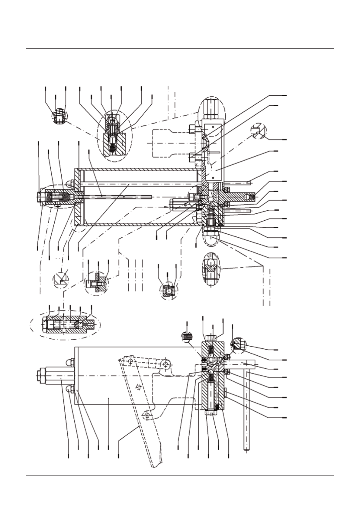
Hydraulic control unit MHP
55
54
34
53
56
33
20
52
58
21
23
31
59
24
51
30
40
35
41
60
28
57
32
25
26
Flow
37
42
regulator
29
39
46
4243 3650 38
44 4548 47 21
50
21
Oil tank
relief valve
27
61
operation
Relief valve
for automatic
43
45
42
18
Relief valve for
7
19
8
6
manual operation
17
16 20
15
14
13
12
27
9
2
1
3
22
4
5
6
8
7
49
10
11
27
Page 28

BIFFI OLGA-H HIGH PRESSURE DOUBLE ACTING HYDRAULIC ACTUATOR
INSTALLATION, OPERATION AND MAINTENANCE MANUAL
PARTS LIST - HYDRAULIC CONTROL UNIT MHP
Item Q.ty Description Material
1 1 Dipstick 2 2 Cap nut Carbon steel
3 2 Washer Carbon steel + rubber
4 1 Hydraulic tank Carbon steel
5 1 Hand pump See attached table
6* 2 O-ring Fluorosilicon rubber
7 2 Ball Stainless steel
8 2 Spring Spring steel
9 1 Washer Carbon steel + rubber
10 1 Screw Carbon steel
11 1 Plate Carbon steel
12 1 Flange Aluminium
13 4 Screw Carbon steel
14 1 Lever Carbon steel
15 1 Distributor Stainless steel
16* 1 O-ring Fluorosilicon rubber
17* 1 O-ring Fluorosilicon rubber
18 1 Nozzle Carbon steel
19 2 Screw Carbon steel
20* 3 O-ring Fluorosilicon rubber
21* 2 O-ring Fluorosilicon rubber
22 1 Tank cover Carbon steel
23 2 Tie rod Carbon steel
24 1 Screw Carbon steel
25 1 Flange Aluminium
26 2 Check valve body Aluminium
27 2 Plug Carbon steel
28 2 Flow control valve setting screw Stainless steel
29 2 Spring pin Stainless steel
30 2 Nut Carbon steel
31 2 Flange Carbon steel
32* 2 O-ring Fluorosilicon rubber
33 2 Spring Spring steel
34 2 Plug Stainless steel
35 2 Retainer ring Spring steel
36 2 Spring pin Carbon steel
37 4 Screw Carbon steel
38 1 Operation instruction plate Stainless steel
39 4 Screw Carbon steel
40 1 Spring Stainless steel
41 1 Ball Stainless steel
42 4 Ball Stainless steel
43 2 Spring Spring steel
44 1 Relief valve setting screw Stainless steel
45 2 Spring pin Carbon steel
46 1 Screw Alloy steel
47 1 Spring Stainless steel
48 1 Nut Carbon steel
49 1 Washer Carbon steel + rubber
50 2 Washer Carbon steel + rubber
51 1 Dipstick Stainless steel
52* 1 Plug + O-ring
53 1 Spring Stainless steel
54 1 Screw Alloy steel
55 1 Nut Carbon steel
56 1 Silencer Brass
57* 2 O-ring Fluorosilicon rubber
58 2 Retainer ring Spring steel
59 1 Dipstick body Aluminium
60 2 Nut Carbon steel
61 1 Relief valve body Aluminium
* Recommended spare parts
28
Page 29
BIFFI OLGA-H HIGH PRESSURE DOUBLE ACTING HYDRAULIC ACTUATOR
INSTALLATION, OPERATION AND MAINTENANCE MANUAL
FIGURE 32A
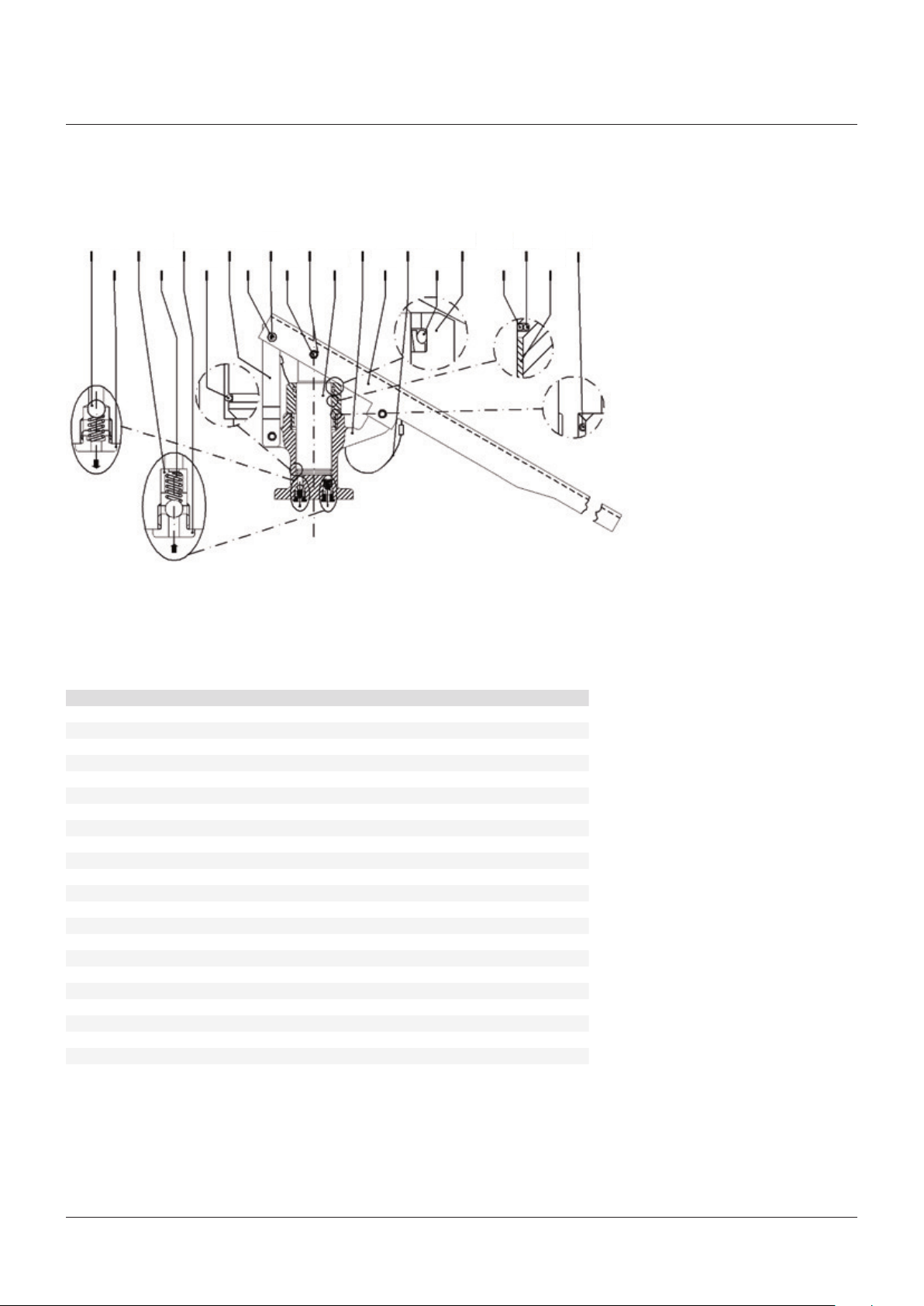
Hand pump
7 13
5 931 11
6 12
19
20
142
PARTS LIST
Item Q.ty Description Material
1 2 Ball Stainless steel
2 1 Delivery valve bush Carbon steel
3 1 Suction valve bush Carbon steel
4 2 Spring Stainless steel
5 1 Suction valve ring Carbon steel
6 1 Spring retainer ring Carbon steel
7 1 Fork Carbon steel
8 2 Pin Stainless steel
9 4 Retainer ring Carbon steel
10 1 Rod Alloy steel
11 1 Body Carbon steel
12 1 Lever Carbon steel
13 1 Split pin with rope Nylon + carbon steel
14 1 Scraper ring PTFE + fluorosilicon rubber
15* 1 Threaded bush Aluminium
16 2 Rod seal ring PTFE + graphite
17* 2 O-ring Fluorosilicon rubber
18* 1 O-ring Fluorosilicon rubber
19* 1 Nut Carbon steel
20 1 Screw Carbon steel
21 1 Fork Carbon steel
22 1 Piston rod bushing Steel + bronze + PTFE
* Recommended spare parts
17 1815
161084
22
29
Page 30
BIFFI OLGA-H HIGH PRESSURE DOUBLE ACTING HYDRAULIC ACTUATOR
INSTALLATION, OPERATION AND MAINTENANCE MANUAL
FIGURE 33
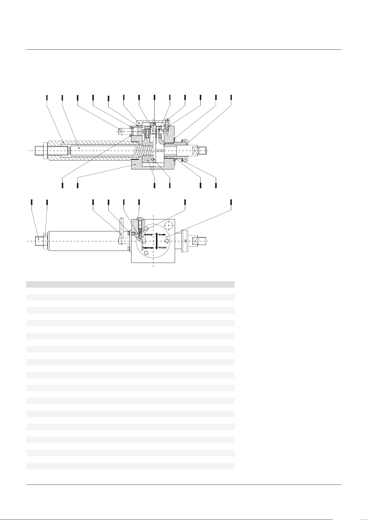
Jackscrew manual override MSJ
4 5 6
3
1
17 18 19
16
15
7 8 9 10 11 12 13 14
20 21 22 23 24 25 26 27 28
ENGAGED
TO OPEN
TO CLOSE
DISENGAGED
PARTS LIST
Item Q.ty Description Material
1 1 Protection pipe Carbon steel
2
3 1 Jackscrew Carbon steel
4 1 Engagement lever pin Stainless steel
5* 1 O-ring Fluorosilicon rubber
6* 1 Cover gasket Fiber
7 1 Cover Carbon steel
8 3 Cam Alloy steel
9 1 Fork Carbon steel
10 3 Spring pin Stainless steel
11 3 Screw Carbon steel
12 1 Screw nut operating cam Alloy steel
13* 1 O-ring Fluorosilicon rubber
14 1 Thrust nut operating cam Alloy steel
15 1 Screw Carbon steel
16 1 Nut Carbon steel
17 1 Flange Carbon steel
18 1 Body Carbon steel
19 1 Spring pin Spring steel
20 2 Screw Carbon steel
21 1 Ball ¼" Stainless steel
22 1 Screw Carbon steel
23 1 Screw nut Bronze
24 1 Pin Carbon steel
25 1 Spring Spring steel
26 1 Bush Bronze
27 2 Thrust shoulder washer Bronze
28 1 Operating instruction plate Aluminium
* Recommended spare parts
30
Page 31

BIFFI OLGA-H HIGH PRESSURE DOUBLE ACTING HYDRAULIC ACTUATOR
INSTALLATION, OPERATION AND MAINTENANCE MANUAL
8 DATE REPORT FOR MAINTENANCE OPERATIONS
Last maintenance operation date:
(in factory, on delivery): …�������������������������������������
����…���������������… exec� by: …�������������������������������……
����…���������������… exec� by: …�������������������������������……
����…���������������… exec� by: …�������������������������������……
Next maintenance operation date:
����…���������������… exec� by: …�������������������������������……
����…���������������… exec� by: …�������������������������������……
����…���������������… exec� by: …�������������������������������……
Start-up date:
(in factory, on delivery): �……………………����������������
(on plant): …�������������������������������������
Biffi reserves the the right to change product designs and specifications without notice�
Biffi Italia S.r.L.
Località Caselle San Pietro, 420, 29017 Fiorenzuola d’Arda (PC) ITALY Ph: +39 (0)523 944 411 E-mail: biffi_italia@biffi�it www.biffi.it
31
 Loading...