


BH 50
L-L 195.00-BM 1 / 60
MANUALE D’USO E MANUTENZIONE
MANUEL D'INSTRUCTIONS
BETRIEBSANLEITUNG
INSTRUCTIONS MANUAL
MANUAL DE INSTRUCCIONES
РУКОВОДСТВО ПО ЭКСПЛУАТАЦИИ И ТЕХОБСЛУЖИВАНИЮ
GENERATORE D'ARIA CALDA
GENERATEUR D'AIR CHAUD
WARMLUFTERZEUGER
SPACE HEATER
GENERADOR DE AIRE CALIENTE
ТЕПЛОВОЙ ГЕНЕРАТОР
BH 50 – BH 100
GAS
IT
FR
DE
EN
ES
RU
L-L 195.00-BM 2 / 60
EN
L-L 195.00-BM 29 / 60
IMPORTANT
Before using the space heater, carefully read all of the instructions and follow them scrupulously. The manufacturer cannot be
held responsible for damage to persons and/or property caused by improper use of the equipment.
This instruction manual is an integral part of the equipment and must therefore be stored carefully and passed on with the unit in
the event of a change of ownership.
1. DESCRIPTION
The space heaters described in this manual are designed to heat
medium or large-size rooms requiring a fixed heating system and, in
particular, to heat greenhouses and/or rooms for breeding animals.
The air required for combustion is sucked directly by the burner (6)
installed in the heater, and can be supplied:
• from the outside by using the flexible connection tube (available
as an accessory), which avoids consuming oxygen in the room to
be heated, or
• from inside the room to be heated. In this case, the room must be
well ventilated to guarantee sufficient exchange of air.
The flow of hot air is moved by the high-efficiency fan (4): air is
heated by the thermal energy generated during la combustion and
heat from the smoke is transmitted to the fresh air through the
metal walls of the sealed combustion chamber and the heat
exchanger. After the combustion products are cooled, they are
conveyed to a discharge duct and eliminated through a chimney or
flue large enough to guarantee their removal.
The space heaters can work with burners having ON-OFF work
modes and can run on natural gas / methane (G20) or L.P.G.
(butane, G30, and propane, G31), according to the different
operating categories approved in European Union countries (Tables
I and II).
Warning
Only burners approved by the manufacturer and listed in
the “TECHNICAL SPECIFICATION TABLE” can be used.
The heater’s certification and warranty will lapse if the
burner is replaced with a non-original model, even if it has
similar specifications.
All of the space heaters are fit with an electronic device that
controls the flame and with:
• safety devices (safety thermostat with manual reset, flame
control, air pressure switch) that trip in case of serious
malfunctions and cause a safety stop. In this case the heater
stops, button (d) lights with a steady red light (Stop Light) and the
heater can resume operation only after the cause of the stop has
been identified and eliminated;
• control devices (fan thermostat, burner thermostat, voltage
control, gas pressure switch) that trip in case of minor operating
faults or supply faults, causing temporary stop of the space
heater. In this case, the heater will restart automatically when the
required condition is restored.
The section “TROUBLESHOOTING” describes all possible operating
faults and their possible remedies.
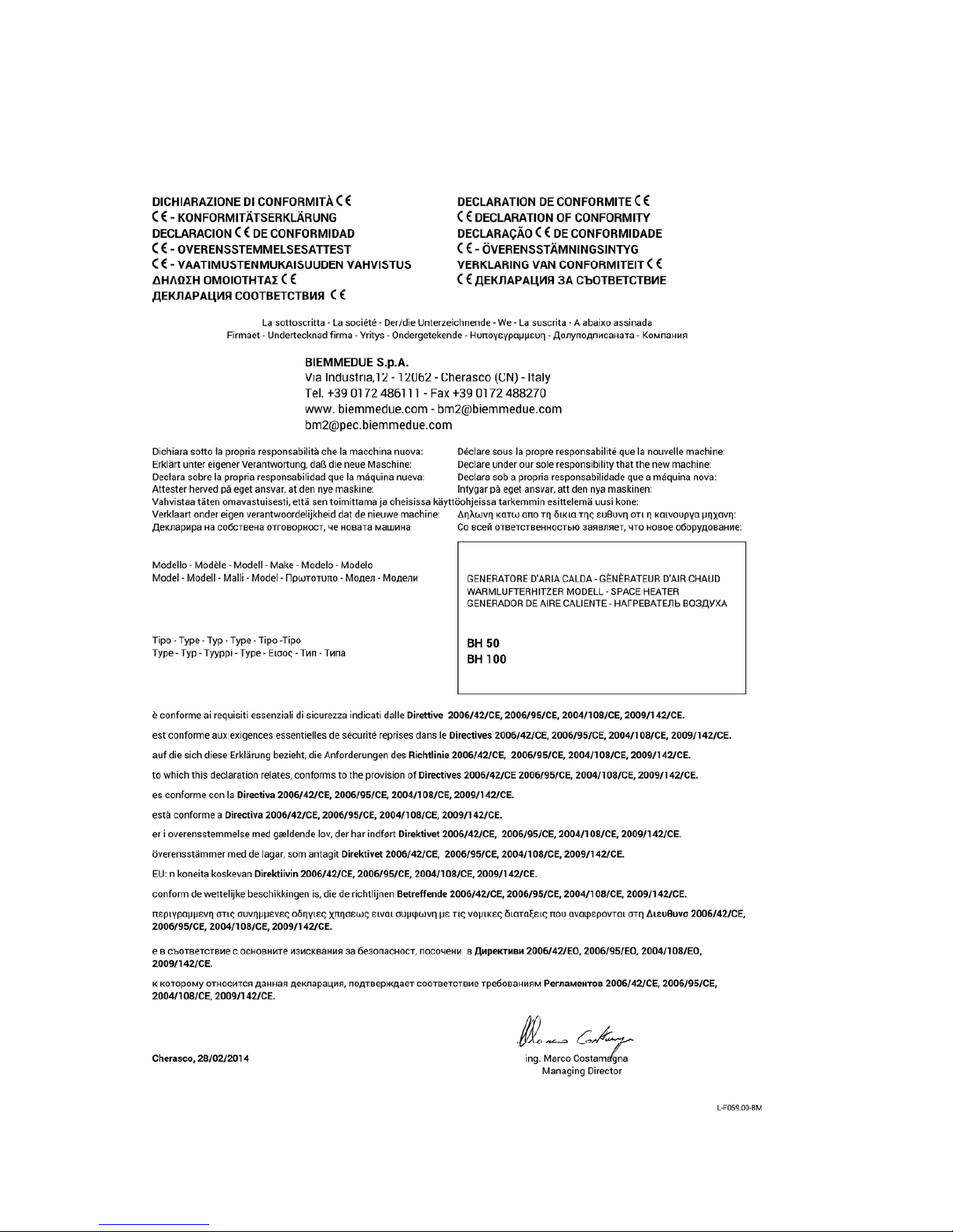
2. CONDITIONS OF SUPPLY
The space heater is delivered packed on a wood pallet and can
easily be handled with a manual or automatic fork lift with capacity
exceeding 200 kg.
Warning
Never try to lift the heater manually: doing so could cause
serious physical injury.
It contains:
• 1 space heater.
• 1 instruction and maintenance manual for the space heater
• 1 instruction and maintenance manual for the burner
• 1 manual with drawing and list of spare parts for the space heater
• 1 manual with drawing and list of spare parts for the burner
3. GENERAL ADVICE
The space heater must be installed, adjusted, and used in
conformity to national and local laws and regulations for its
operation.
General guidelines:
• Follow the instructions in this booklet very carefully;
• Do not install the heater in places where there is a risk of fire or
explosion;
• Keep inflammable material at a safe distance from the heater
(minimum 3 metres);
• Check that there is no overheating of walls, ceilings or floors made
of inflammable materials.
• All fire prevention regulations must be complied with;
• The room being heated must be sufficiently ventilated so that the
heater has enough air to function properly;
• The heater must be near a chimney or chimney flue and an
electrical panel conforming to declared specifications;
• Check the heater before switching it on and at regular intervals
during its use;
• After use, make sure the disconnecting switch is off.
When using any type of space heater it is obligatory:
• not to exceed the maximum heat output level of the furnace
(“TECHNICAL SPECIFICATION TABLE”);
• make sure that the air flow is not below the rated level; check that
there are no obstacles or obstructions to the air suction and/or
delivery ducts, such as sheets or covers on the equipment, walls
or large objects near the heater.
Warning
This unit may not be used by persons (including children)
with reduced physical, sensorial or mental capacities or
with limited experience and familiarity unless they are
under supervision or instructed on how to use the unit by
the person responsible for its safety.
4. INSTALLATION INSTRUCTIONS
Warning
All of the operations described in this section must be
performed by professionally qualified personnel only.
EN
L-L 195.00-BM 30 / 60
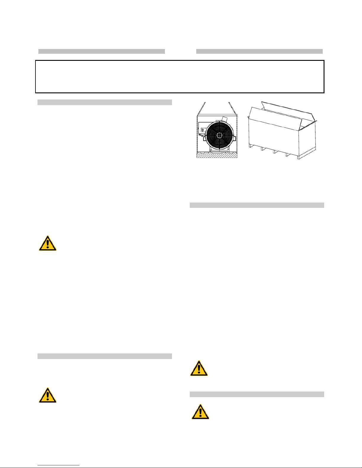
4.1. INSTALLATION ON FLOOR OR CEILING
The space heater can be installed on a support base, which must be:
• stable and horizontal
• made of non-combustible material
Accessories include support hooks to suspend the heater by
hooking it to the ceiling with ropes and/or chains of appropriate
capacity and length, to be attached to the four suspension points
Warning
Make sure that the ropes and/or chains form an angle not
more than 5° with vertical to the ceiling, that the ropes do
not cross, and that a different rope is used for each hook.
The minimum distance from surrounding walls, floor and/or ceiling
must always be at least 1 metre.
4.2. POWER CONNECTIONS
Warning
The power line must be earthed and fitted with a residual
current circuit breaker.
The power cable must be connected to a panel fitted with
a cut-out.
Before switching on the heater and, therefore, before plugging it into
the electrical power supply, check that the power supply
specifications are the same as those stated on the identification
plate.
Warning
The heater is fitted with a temporary power cable, used for
the working test.
Warning
The temporary power cable must be removed and replaced
with a H07RN-F cable having a section of at least 1.5
mm
2
: a larger section is required if the cable is more than
25 metres long.
The cable must be stripped, leaving the earth lead at least
2 cm longer.
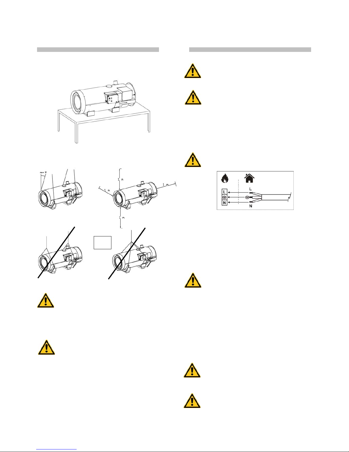
The electrical power cable must be connected in conformity to the
polarity specified on the main terminal board of the electrical panel:
phase (L) and neutral (N).
Warning
If polarities L and N are incorrect, the space heater may
stop a few seconds after it is switched on for the first
time.
If any room thermostat or other accessories are connected to the
system (such as the timer for example) this must be done by
connecting the electrical cable to the thermostat plug (c):
• Take the plug (c) out of the power switchboard, open it and
remove the electrical jumper between terminals 2 and 3 of the
plug;
• Connect the thermostat electrical cable to terminals 2 and 3 of the
thermostat plug (c);
• Close the plug again and plug it back into the power switchboard.
Warning
Never attempt to switch the heater on or off by connecting
the room thermostat (or other control devices) to the
electrical power line.
The installation and connection of all the other accessories are
described in the specific instructions included with each accessory,
together with operating instructions.
The electrical diagram shown in this manual refers to the electrical
connection only.
4.3. CONNECTION TO HOT AIR DELIVERY DUCTS
The space heater is set to operate with direct distribution of air.
Nevertheless, it can be connected to appropriately sized air
distribution channels, if required, with maximum diameter and
length as shown in the “TABLE OF TECHNICAL CHARACTERISTICS”.
Warning
Before starting the heater, check that the direction of
rotation of the fan matches the direction shown on the fan
itself.
4.4. CONNECTION TO FUEL SUPPLY
Warning
The heater must be installed, set up, and used in
compliance with all applicable regulations.
NO
EN
L-L 195.00-BM 31 / 60
Warning
Before installing, check the gas supply conditions
required for the type of gas chosen and for the EU country
of installation (Tables I and II).
The gas supply pipe must be properly sized, conform to the installed
thermal power, and guarantee the necessary conditions for gas
supply.
Warning
The gas supply pressure must be guaranteed during
heater operation and not with the heater off.
The space heater has a gas ramp with: gas filter, pressure regulator,
safety electrovalve, work electrovalve, pressure stabilizer, pressure
valve.
It is good practice for the installer to set up the supply line as
follows:
1: filter-pressure regulator of filter
2: antivibration joint
3: stopcock
4: gas ramp
Parts (1), (2) and (3) are available as accessories and are not
supplied with the heater.
When the line has been connected:
• Bleed the gas supply pipe;
• Check that the gas pipe is sealed.
• Open the gas stopcock and check the seal of all connections to
the heater.
4.5. CONNECTING BURNER TO “SNORKEL” AIR INTAKE AND
SETTING COMBUSTION AIR
The burner air intake (3) can be connected outside the room to be
heated in order to suck in clean air and avoid depleting the oxygen
in the room.
The connection pipe must be rigid to prevent shrinking due to air
intake depression. It must have a minimum diameter of 100 mm and
maximum length of 6 metres.
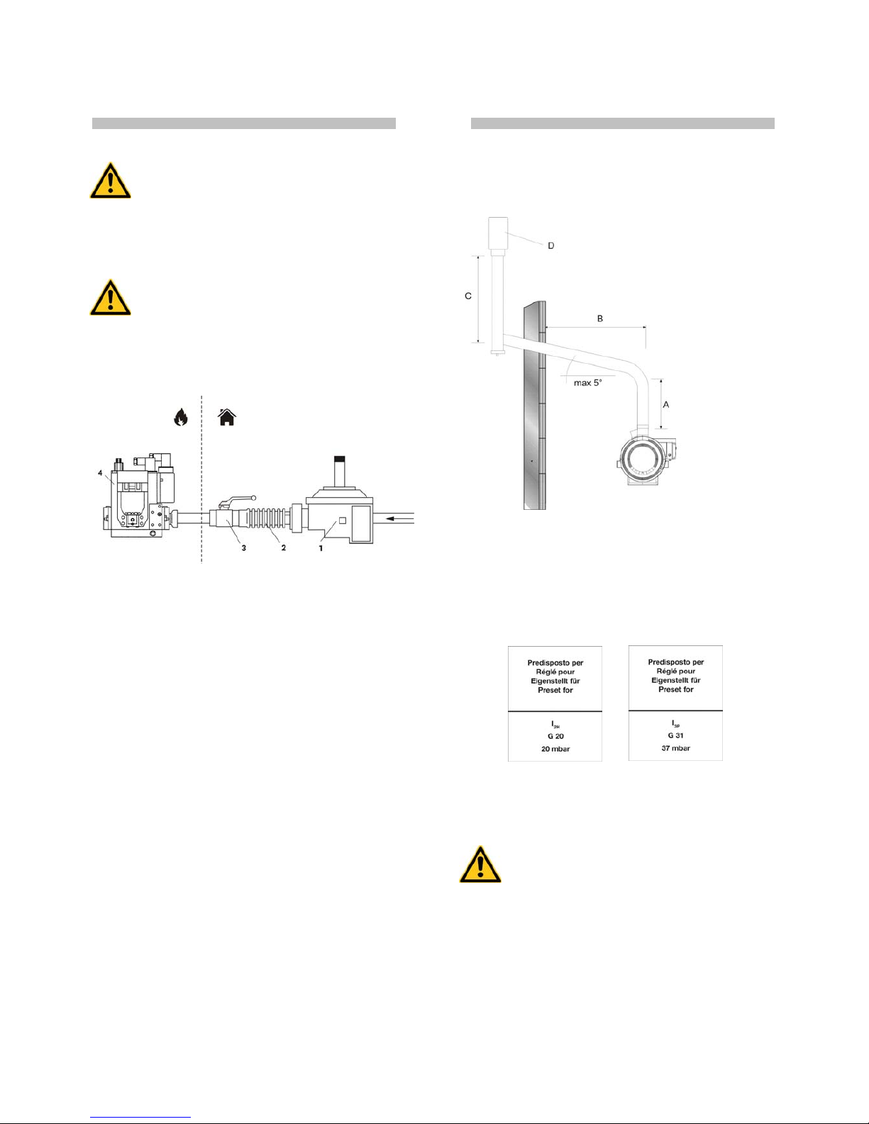
4.6. CONNECTION TO EXHAUST DUCT
Exhaust ducts must be in steel and conform to EN 1443.
Efficient combustion and trouble-free working of the burner depend
on efficient flue draft. The unit must be connected to the chimney
flue in compliance with current legal regulations and in line with the
following guidelines:
• the flue must be as short and possible and with ascending slope
(minimum height 1 m);
• There should be no sharp curves in the pipes, and the diameter of
the pipes must never be reduced;
• there must always be a wind deflector to prevent the entrance of
rain and to prevent smoke from being blocked by the wind;
• Flue draft must at least equal the level in the Technical
Specifications.
• Every heater must have its own chimney;
The following diagrams show possible flue positions:
A) Minimum 1 m
B) As short as possible
C) Minimum 1 m
D) Chimney draught H shape
4.7. FIRST START-UP
The heater is set up for one of the operating categories on Tab. I:
the adhesive label on the gas valve group (4) indicates the appliance
category (usually category I2H, G20 / 20 mbar).
Before starting the heater, consult Tab. I to identify the work
category made compulsory by European and national reference
standards and corresponding to the country of installation.
Warning
If the work category is incorrect, you MUST recalibrate the
burner
Specifically:
• If indicated in Tab. I, replace the nozzle (see the burner manual
for instructions);
• Calibrate the gas pressure switch (5) on the gas ramp by
adjusting it to 70% of supply pressure
• Adjust the gas ramp pressure regulator to the value shown on
Tab. I.
 Loading...