

Page 1
Manual
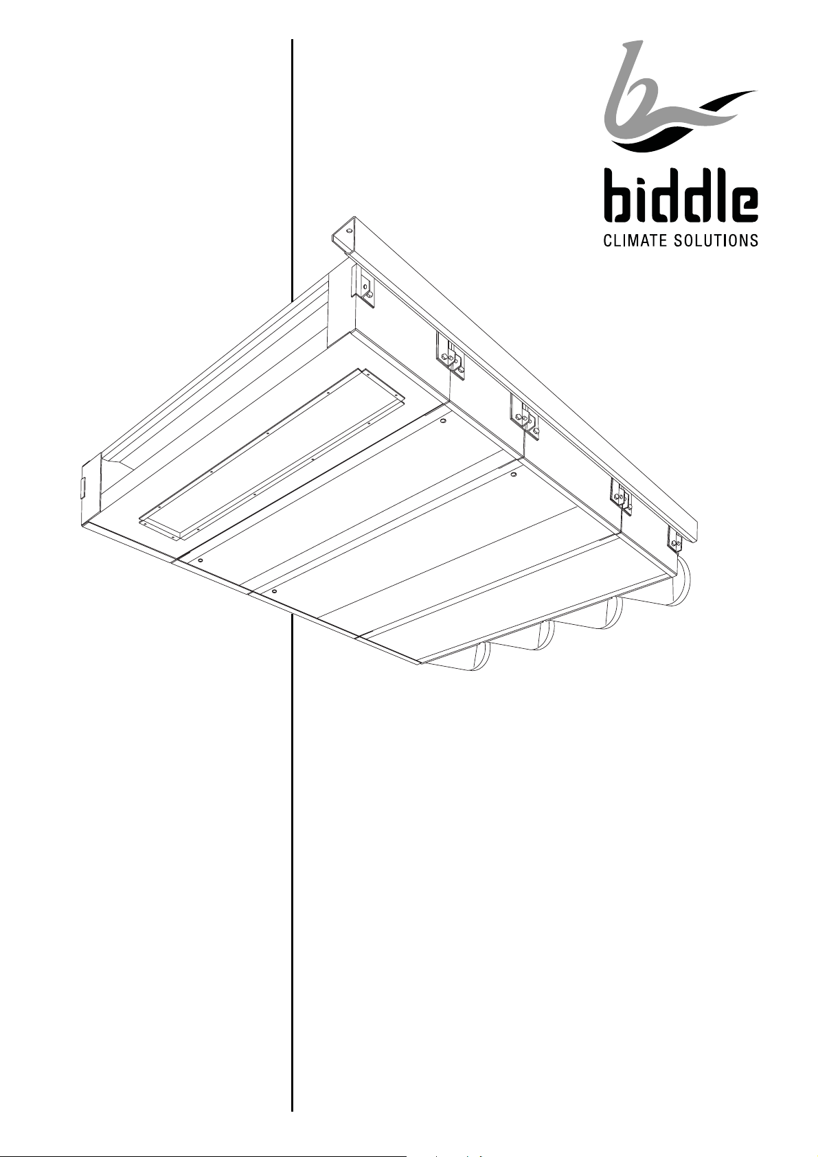
Modular fan coil unit
Model PS
Version 2.1
07-2018
17-
Q P
English
Page 2

B
Copyright
All the information and drawings in this manual are the property of Biddle and may not be
used (other than for the actual operation of
the device), photocopied, duplicated, translated and/or be brought to the attention of
third parties without Biddle’s prior written
permission.
The name Biddle is a registered trademark.
Trademarks
The name Biddle is a registered trademark of
Biddle bv.
Warranty and liability
Please refer to Biddle's Terms of Sales and
Delivery for warranty and liability conditions.
For more information
If you have any comments or questions
about specific topics relating to this product,
please do not hesitate to contact Biddle.
Addresses
United Kingdom
Biddle Air Systems Ltd.
St. Mary’s Road
Nuneaton
Warwickshire CV11 5AU
United Kingdom
telephone: 024 7638 4233
fax: 024 7637 3621
e-mail: sales@biddle-air.co.uk
internet: www.biddle-air.com
Biddle excludes liability for consequential
loss at all times and under all circumstances.
Liability for the contents of
this manual
However much care might have been taken
in ensuring the correctness and, where necessary, completeness of the description of
the relevant parts, Biddle disclaims all liability
for damage resulting from any inaccuracies
and/or deficiencies in this manual.
Should you detect any errors or ambiguities
in this manual then we would be pleased to
hear from you: it helps us to improve our
documentation even further.
Biddle retains the right to change the specifications stated in this manual.
Other countries
Biddle Export
PO Box 15
NL-9288 ZG Kootstertille
The Netherlands
telephone: +31 512 335555
fax: +31 512 335554
e-mail: export@biddle.nl
internet: www.biddle.info
2
Manual model PS
Page 3

Modular fan coil unit Contents
2.7 Connecting the valve motor............ 12
Contents
2.8 Connecting ducts ............................ 12
2.9 Connecting the unit to the CH
1 Introduction ........................4
1.1 About this manual ............................. 4
1.2 How to use this manual .................... 4
1.2.1 Marginal symbols in the manual ......... 4
1.2.2 Pictograms used on the unit and in
the manual................................................... 4
1.2.3 Related documentation....................... 4
1.3 About the unit.................................... 5
1.3.1 Applications ........................................ 5
1.3.2 Working............................................... 5
1.3.3 Modules .............................................. 5
1.3.4 Type code ........................................... 6
1.3.5 Type plate ........................................... 6
and/or CW system ................................ 12
2.9.1 Water connections............................ 12
2.9.2 Frost protection................................. 13
2.9.3 Connecting water pipes .................... 13
2.10 Connecting the condensate drain. 13
2.10.1 Particulars....................................... 13
2.10.2 Connecting the condensate drain... 13
2.11 Connecting the unit to mains
power supply......................................... 14
2.11.1 General........................................... 14
2.11.2 Connecting to mains....................... 14
2.12 Installing the controller.................. 14
2.13 Switching on and checking
operation............................................... 14
1.4 Components ..................................... 6
1.4.1 Required components......................... 6
1.4.2 Accessories ........................................ 7
1.4.3 Parts not supplied............................... 7
1.5 Safety instructions ............................ 7
1.5.1 Operation............................................ 7
1.5.2 Installation, maintenance and
service ......................................................... 7
2 Installation..........................8
2.1 Safety instructions ............................ 8
3 Maintenance ....................16
3.1 Safety instructions .......................... 16
3.2 Replacing the filter .......................... 16
3.2.1 Introduction....................................... 16
3.2.2 Replacing flat-bed filter in base
module....................................................... 16
3.2.3 Replacing bag-type filter or pleated
filter............................................................ 16
3.3 Cleaning.......................................... 16
3.4 Scheduled maintenance ................. 16
2.2 Delivery check .................................. 8
2.3 General instructions.......................... 8
2.3.1 Order of working ................................. 8
2.3.2 Miscellaneous..................................... 8
2.4 Installing the wall duct ...................... 8
2.5 Installing the roof duct ...................... 9
2.6 Suspending the unit........................ 10
2.6.1 Positioning ........................................ 10
2.6.2 Installing the suspension rail............. 10
2.6.3 Suspending and securing modules....11
4 Service.............................18
4.1 Safety instructions .......................... 18
4.2 Opening the unit ............................. 18
4.2.1 Base module..................................... 18
4.2.2 Electronics compartment .................. 18
4.3 Fuses .............................................. 19
4.4 High-limit thermostat....................... 19
Version 2.1 English (17-07-2018)
3
Page 4
B
1 Introduction
1.1 About this manual
d
Danger:
This indicates actions which are not permitted. Ignoring this warning may lead to
serious damage or accidents that may
involve physical injury.
This manual describes the installation and
maintenance of the modular fan coil unit,
model PS.
This manual only relates to the unit itself. A
separate manual covers the operation and
control of the unit.
1.2 How to use this manual
For unit
With ... module:
The description applies only to models that
have the feature referred to.
If no specific model is referred to, the description applies to all models.
1.2.2 Pictograms used on the unit and
in the manual
The below pictograms refer to possible risks
or dangers. These pictograms can also be
found on the unit.
ê
s with … :
w
Warning:
You are entering an area which
contains live components.
1.2.1 Marginal symbols in the manual
n
Note:
Draws your attention to an important part of
the text.
c
Caution:
If you do not carry out this procedure or
action correctly, you may damage the unit.
So, follow the instructions carefully.
w
Warning:
If you do not carry out this procedure or
action correctly, you may cause material
damage and/or physical injury.
So, follow the instructions carefully.
Accessible to qualified maintenance staff only. Caution is
urged.
ç
1.2.3 Related documentation
Besides this manual, the following documents come with the unit:
- documentation for control and operation
(if applicable);
- wiring diagram for installation and service purposes.
w
Warning:
This surface or part can be hot.
There is a risk of burns on contact.
4
Manual model PS
Page 5
Modular fan coil unit 1 Introduction
1.3 About the unit
1.3.1 Applications
The modular fan coil unit is designed for
heating, cooling and/or ventilating rooms.
The inlets and outlets of the unit are positioned in such a way that the discharged air
flow is distributed evenly across the room
without causing discomfort to the people in it.
The unit’s dimensions are geared to integrating the unit in suspended ceilings.
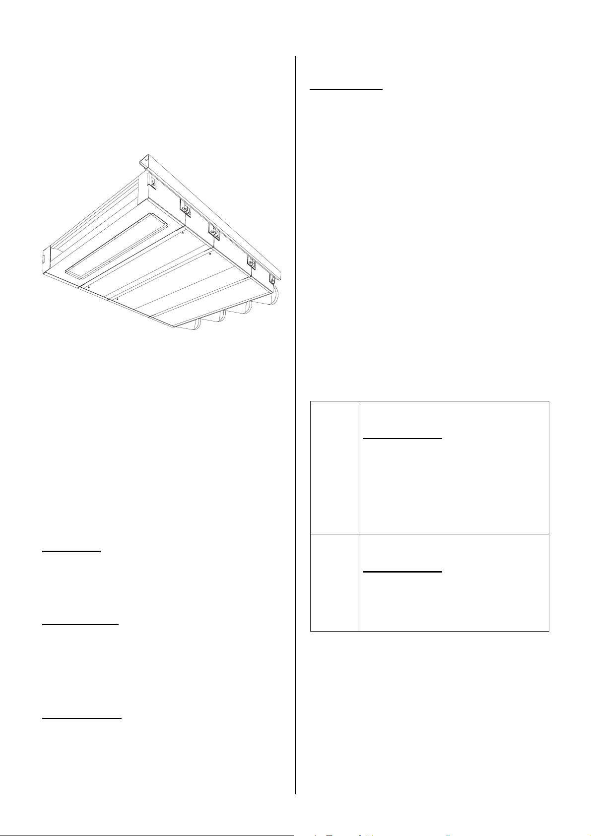
1.3.2 Working
The fan coil unit blows a flow of air into the
room. The air may be taken in, at the user’s
option, either from outside (ventilation) or
from the room itself (recirculation). Thus, the
unit offers two benefits:
- The room is kept at the desired temperature.
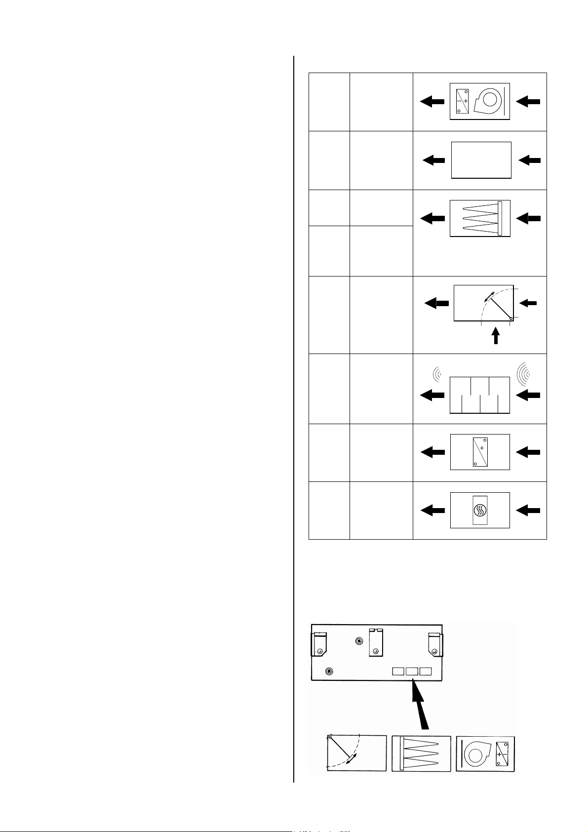
Type references and symbols of modules
PS B
PS P
PS F
PS FP
PS L
PS G
base
module
plenum
module
filter
module
pleated
filter
module
air valve
module
attenuation
module
- Gradual deterioration of air quality in the
room is counteracted.
1.3.3 Modules
A modular fan coil unit is made up of modules. Each module has its specific function.
By combining different modules, modular fan
coil units with different features can be composed.
PS V
PS VE
heating
module
(water)
heating
module
(electric)
The symbols can be found on the underside
of each module. On the base module, these
symbols indicate the order of the modules of
the delivered modular fan coil unit.
Version 2.1 English (17-07-2018)
5
Page 6
B
1.3.4 Type code
The type references, when combined, constitute the type code of the unit's modules, for
instance:
PS B-20-H1-M
PS P-21
PS G-40
PS V-61-H1C3-I
Various combinations can be made.
Explanation of type code
series
module
capacity
with base
module and/or
heating module:
heating and/or
cooling
with base
module:
electronic
control
PS
B, P, F, FP,
L, G, V, VE
20, 21, 40,
41, 60, 61
H1, H2,
H3, H4
C3, C4
H1C3,
H2C2
HE
M
S
modular fan
coil unit
see Section
1.3.3
water heating
water cooling
water heating
and cooling
electric heating
modulating
control
speed control
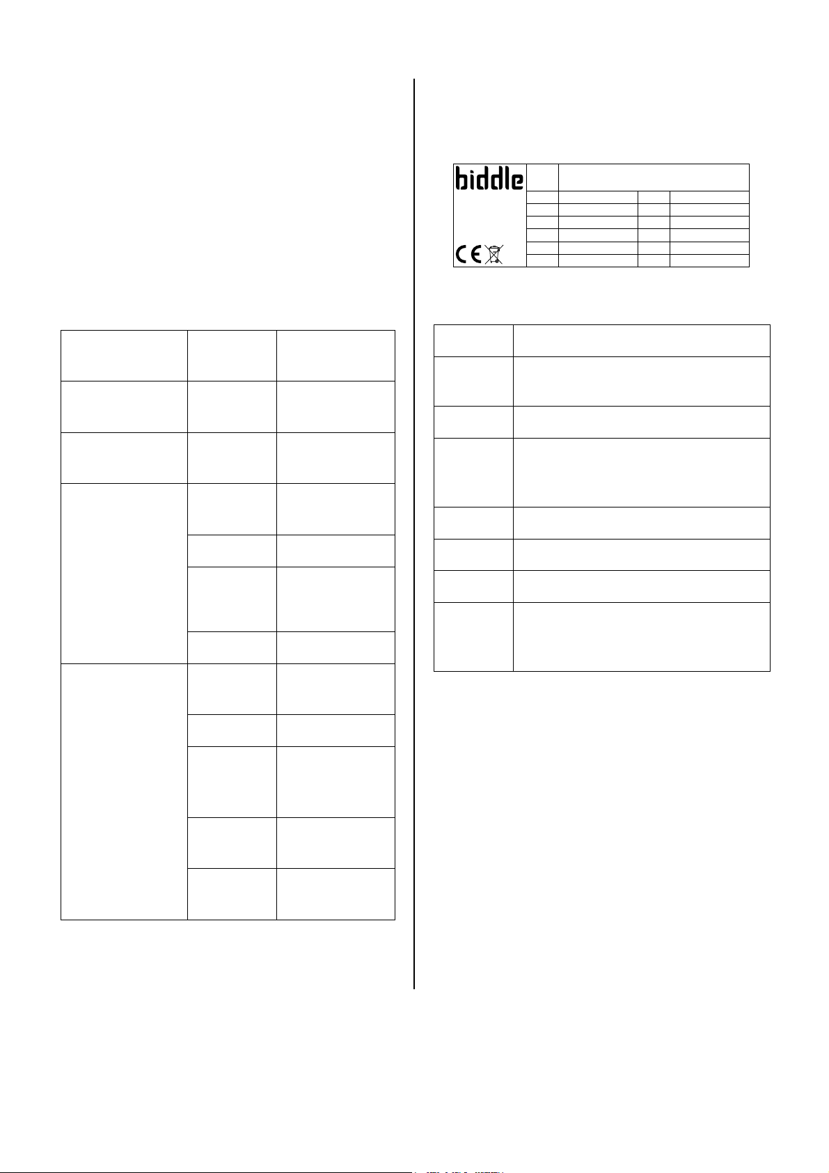
1.3.5 Type plate
The type plate is located on the base module.
Type PS B-40-H2-M
Biddle bv
Markowei 4
NL-9288 HA Kootstertille
Example of a type plate
References on the type plate
Type
Code
M
P
max
U
I
max
P
motor
P
heating
Code U 230 V ~ 50 Hz
4023
Nº 123456/1-1 07-12 I
M 51 kg I
Medium LPHW P
p
600 kPa P
max
max
I
max
max
motor
heating
L1 0.88 A
L2 -
L3 -
0.20 kW
-
full type code of unit
if applicable:
unit code of electronic control
weight of unit
with water heating:
maximum allowable operating
pressure
supply voltage
maximum amperage
maximum power absorbed by fans
with electric heating:
maximum power absorbed by heating
1.4 Components
6
I
B
without
reference
Interface, either
with or without
touch control
Basic, without
control
not described
in this manual
1.4.1 Required components
The following components are delivered
separately but are always required:
- mounting kit, consisting of a suspension
rail and fasteners for linking modules
- electronic control system components,
such as a controller, control cables, etc.
(see the documentation of the control
system)
Manual model PS
Page 7

Modular fan coil unit 1 Introduction
1.4.2 Accessories
The following optional accessories are available:
- water control unit
- servomotor for air valve module
- ventilation module for the control of an
extractor fan
- wall sleeve
- external air intake grille
- roof cap
- duct connection (PS TH and PS TV)
- flexible connection sleeves, with or with-
out connecting flange
- wall and ceiling grilles, fixed or adjustable
- condensate drain tray
- condensate discharge pump
1.5.2 Installation, maintenance and
service
w
Warning:
The unit may be opened by qualified
technical staff only.
ê ç
Before opening the unit:
- Switch the unit off using the controller.
- Wait until the fans have stopped rotating.
- Allow the unit to cool down as the heat
exchanger or heating element can get
very hot.
- Disconnect the mains supply.
- Shut off the CH and/or CW supply (if
possible).
1.4.3 Parts not supplied
The following parts are not supplied by
Biddle and should be procured from other
suppliers:
- threaded suspension rods (M8)
- mounting rail
1.5 Safety instructions
1.5.1 Operation
w
Warning:
Do not put any objects in the inlets and
outlets.
Do not block the inlets and outlets.
w
Warning:
The fins of the heat exchanger are sharp.
ç
The upper surface of the unit can become
hot during operation.
Version 2.1 English (17-07-2018)
7
Page 8

B
2 Installation
2.1 Safety instructions
2.3.2 Miscellaneous
c
Caution:
The infiltration of coarse dust, cement, etc.
may damage the unit. So long as such contaminants are in the room,
w
Warning:
Installation works may be performed by
qualified technical staff only.
Before opening the unit, follow the safety
instructions in Section 1.5.
2.2 Delivery check
- Check the unit and its packaging for
correct delivery. Report any transport
damage to the driver and supplier immediately.
- Make sure that all parts and components
have been supplied (see Section 1.4).
Report any defects to the supplier immediately.
- do not put the unit into operation;
- cover the inlets and outlets.
2.4 Installing the wall duct
Accessory, only in combination with air valve
module (PS L)
The wall duct is made up of a wall sleeve
and an external air intake grille. The wall duct
is made up of two parts which are slid into
one another.
B
A
2.3 General instructions
2.3.1 Order of working
Biddle recommends following the order of
working described in this section for performing the installation works.
n
Note:
Make sure you perform all operations that
are required for the installation of your unit.
Check the type plate and refer to Section
1.3.5 if you are not sure about the model or
type of your unit.
Opening dimensions for wall duct
type opening, A x B wall thickness
PS 20, 21
PS 40, 41
PS 60, 61
1 Apply the included expanding foam gas-
ket around the ventilation opening of the
air valve module.
2 Make an opening in the wall.
628 x 142 mm
1003 x 142 mm
1503 x 142 mm
200 – 350 mm
or
350 - 650 mm
(dep. on type)
8
Manual model PS
Page 9

Modular fan coil unit 2 Installation
3 Fix the duct sections as you please, e.g.,
by bricking them in or by fixing them with
screws. If using screws, mind their positions: the screws must not hinder the installation of the external grille.
n
Note:
Seal any gaps between sleeve and wall in a
draught- and leakage-free manner.
4 Drill the (∅ 5mm) grille fixing holes into
the flanges of the sleeve section that is
fixed to the outer wall.
5 Apply paste onto the inner side of the
grille flanges. The paste is to seal off the
gap between grille and sleeve in a
draught- and leakage-free manner.
6 Fix the grille to the flanges using sheet
metal screws.
1
B
A
Opening dimensions for roof duct
type opening, A x B
PS 20, 21
PS 40, 41
PS 60, 61
1 Apply the included expanding foam gas-
ket around the ventilation opening of the
air valve module.
628 x 145 mm
1003 x 145 mm
1503 x 145 mm
Tar mastic
Timber 70x70
c
Caution:
Place the grille with the blades correctly
positioned: oriented outward to allow for runoff.
2.5 Installing the roof duct
Accessory, only in combination with air valve
module (PS L)
The roof duct is made up of two parts: a roof
curb and a roof cap. The roof cap consists of
a cover and a sleeve. On delivery, these are
attached to one another.
2 Make an opening in the roof.
3 Make a water-tight curb 1 around the
opening.
4 Detach the cap from the sleeve. To do
so, loosen the screws in the upper side
of the sleeve.
2
5 Insert the sleeve into the opening. Con-
nect sleeve and curb by fixing screws 2
through the sleeve’s inner side.
6 Mount the cap to the sleeve.
n
Note:
Seal any gaps between sleeve and roof in a
draught- and leakage-free manner.
Version 2.1 English (17-07-2018)
9
Page 10

B
2.6 Suspending the unit
2.6.1 Positioning
- Make sure that the structure from which
the modules are to be suspended can
carry the weight of the whole modular fan
coil unit.
Module weights
PS 20, 21 PS 40, 41 PS 60, 61
PS B
PS P
PS F, FP
PS L
PS G
PS V, VE
- Suspend the unit at a minimum height of
1.8 m.
- Suspend the modules level. This results
in proper venting of the heat exchanger
and (for units with cooling) in proper discharge of condensate.
32 kg 51 kg 62 kg
8 kg 10 kg 12 kg
10 kg 13 kg 16 kg
13 kg 16 kg 20 kg
18 kg 24 kg 31 kg
15 kg 19 kg 22 kg
2.6.2 Installing the suspension rail
The modules are hooked into the included
suspension rail n one side. On the opposite
side (connection side), the modules are
suspended from a thread rod. The suspension rail may either be suspended from a
thread rod 1 (as illustrated above) or be
mounted directly onto the ceiling (as illustrated below).
1 Make a suspension structure using
thread rods, mounting rails and the supplied suspension rail. On each thread
rod, apply two nuts at an intermediate
distance of about 4 cm 2.
- Provide for proper sealing if wall or roof
sleeves and the like are installed. Improper installation can cause draught
and condensate problems.
- Ensure the air can flow freely through the
unit’s inlets and outlets.
- Position the unit such that the modules
will be easy to access both during and
after installation.
190
Centre distance between mounting rails and
suspension rails
PS 20, 21 PS 40, 41 PS 60, 61
A
n
Note:
- Keep a minimum distance of 190 mm
between the centre of the suspension rail
and a wall or obstacle, such as a pillar.
This is to allow the modules to be
hooked in.
- Mount the rails in line with a possible
opening for a roof or wall sleeve.
782 mm 1157 mm 1657 mm
A
10
Manual model PS
Page 11

Modular fan coil unit 2 Installation
2.6.3 Suspending and securing
modules
5 Interlink the modules 7.
c
1 The base module (PS B) and the at-
tenuation module (PS G) are provided
with a securing bracket 3. Remove it.
Caution:
When linking the modules, do not fully press
the rubber seal 8 together.
Ensure that the air valve module, if any, is
attached to the roof or wall duct in a draughtfree manner.
2 Hook the modules into the suspension
structure one by one. Hook the suspension brackets 4 into the suspension rail
on the one side, and the suspension
hook 5 in the thread rod on the other
side.
In suspending the modules, follow the
order that is indicated in the schedule on
the base module (see Section 1.3.3).
3 Using the thread rods, adjust the mod-
ules vertically so that they are level.
6 Re-attach the securing bracket 9, which
was removed in step 1, to the relevant
module(s).
w
Warning:
Make sure that the module(s) is (are) secured. Unsecured suspension may lead to
a module falling out of the suspension
structure.
4 Secure the suspension hook 6 between
the two nuts on the thread rod.
Version 2.1 English (17-07-2018)
11
Page 12

B
2.7 Connecting the valve
motor
Accessory with air valve module (PS L)
The air valve module is available with a premounted valve motor. If the module does not
yet have a valve motor, you must mount it
first.
1 Both the valve motor and the base mod-
ule have a cable with a connector. Connect these.
Connection through rectan-gular ducts is
possible with the duct connections
and PS TV, using flexible connection sleeves
(not illustrated).
Mounting the ducts depends on the local
situation, and is to be carried out according
to your own judgment. However, follow the
below instructions in order not to affect the
unit’s performance:
- Avoid any abrupt duct transitions.
- Keep ducts as short as possible.
- Mount flexible connection sleeves to the
intake opening under slight tension (this
is to prevent the connection sleeve from
being sucked to a close at high fan
speeds).
PS TH
2 You may want to set a stop to the valve
motor.
This allows you to open the air valve partially, so the unit will ventilate and recirculate at the same time.
2.8 Connecting ducts
Only with plenum PS P or duct
connections PS TH and PS TV
The plenum module PS
the modular fan coil unit to be connected, via
circular ∅ 200 mm ducts, to a discharge or
intake opening.
P (illustrated) allows
- Provide for proper sealing at transitions
in the duct system.
2.9 Connecting the unit to the
CH and/or CW system
Only for units with water heating and/or cooling
2.9.1 Water connections
Depending on the type, the connections have
female-thread fittings or compression fittings.
The heat exchanger may come with premounted control valves. If so, the CH and/or
CW pipes are to be connected to them.
The connections are marked with arrows that
indicate either supply or return: with heating,
the arrows are red; with cooling, blue.
12
Manual model PS
Page 13

Modular fan coil unit 2 Installation
2.9.3 Connecting water pipes
1 Lay the water pipes, and connect them to
the screwed or compression fittings.
c
Caution:
Tighten the compression fittings well.
The (1/8") vent cocks 1 are mounted to the
collectors of the heat exchanger, protruding
from the side of the module.
c
Caution:
Biddle recommends the inclusion of a valve
in each pipe.
Operating pressure for CH and CW systems
temperature maximum
operating
pressure
screwed fittings
compression fittings all 3 bar
< 20° C 16 bar
< 93° C 10 bar
< 110° C 6 bar
2 Fill the CH and/or CW system.
3 Vent the heat exchanger.
4 Check the connections for leaks.
2.10 Connecting the
condensate drain
Only for units with cooling
2.10.1 Particulars
2.9.2 Frost protection
Only for units with ventilation
Depending on the control system, the unit
has a frost protection thermostat or a controller-integrated protection.
c
Caution:
This reduces the risk of the heat exchanger
freezing but does not warrant 100% protection.
Prevent the heat exchanger from freezing:
- Provide for constant circulation of the
water at the right temperature.
- Add glycol to the water when the unit is
not in operation during the wintertime.
The unit has two (∅ 15mm) condensate wa-
ter drains 2. One of the drains must be fitted
with a stink trap and connected to the sewer.
The second drain is closed with a compression cap but can be used if necessary.
The unit can be provided with a condensate
drain tray and/or a condensate pump (accessories). If so, their drains must be connected.
2.10.2 Connecting the condensate
drain
1 Install a sewer connection incl. stink trap.
2 Connect the condensate drain tray to a
flexible hose.
3 Connect the hose, with a stink trap, to
the sewer.
Version 2.1 English (17-07-2018)
4 Insulate the pipes that are not hanging
over the condensate drain tray.
13
Page 14

B
2.11 Connecting the unit to
mains power supply
2.11.1 General
w
Warning:
The unit must be earthed.
The unit must be connected in accordance with all applicable local laws and
regulations.
c
Caution:
Do not switch the unit on and off with the
mains switch but rather with the controller.
2.11.2 Connecting to mains
For units with water heating and/or cooling:
2.12 Installing the controller
Depending on the type, the unit can be fitted
with an electronic controller. Install it according to the respective manual.
The connections are located on the electronics compartment or on the control unit's PCB
in the compartment (see Section 4.2.2).
1 Install an earthed wall socket at no more
than 1.5m from the connection side of
the base module.
c
Caution:
Do not yet insert the plug into the wall
socket.
For electrically heated units:
1 Install an all-pole switch with a minimum
contact distance of 3 mm.
2 Connect the switch to the mains.
w
Warning:
Make sure that the mains supply
group is switched off.
3 Connect the unit to the switch according
to the wiring diagram.
2.13 Switching on and
checking operation
For all units:
1 Check if all modules are correctly sus-
pended and secured.
2 Check the order of installation of the
modules (see Section 1.3.3).
3 Check the connection to the mains.
4 Check the controller connections (see
the corresponding documentation).
5 Switch on the mains supply.
6 Make the controller ready for use accord-
ing to the appropriate manual.
7 Switch on the unit using the controller.
Check whether the unit blows out air.
For units with water heating and/or cooling:
c
Caution:
Do not yet switch the mains supply group on!
14
Check if the heat exchanger is properly connected:
8 Make sure the CH and/or CW system is
(are) switched on.
Manual model PS
Page 15

Modular fan coil unit 2 Installation
9 Let the unit heat and/or cool using the
controller. Feel whether the discharged
air is getting hot (if heating) or cold (if
cooling).
10 Vent the heat exchangers if necessary.
For units with cooling and condensate discharge pump (accessory):
Check the working of the condensate discharge pump:
11 Pour water into the external drip tray.
The condensate pump should start working shortly.
For units with air valve module:
12 Check the seal of the fresh air duct: it
should be draught-free.
13 Check whether the air valve closes off
the ventilation opening properly in both
modes.
14 Let the unit ventilate and recirculate
using the controller. Check whether the
air valve moves to the right position.
For units with an air valve module featuring a
valve motor with spring return:
15 Switch off the mains power supply and
check whether the valve automatically
closes the duct.
16 Switch on the mains supply and check
whether the valve works normally again.
Version 2.1 English (17-07-2018)
15
Page 16

B
3.2.3 Replacing bag-type filter or
3 Maintenance
3.1 Safety instructions
w
Warning:
Maintenance works may be performed by
qualified technical staff only.
Before opening the unit, follow the safety
instructions in Section 1.5.
3.2 Replacing the filter
3.2.1 Introduction
The filter must be replaced regularly. A dirty
filter may cause inadequate heating, cooling
or ventilation as well as a high noise level.
The interval at which the filter is to be replaced depends on the use of the room.
New filters are available from Biddle. You
may also clean the filter material with, for
instance, a vacuum cleaner. After some
cleanings, however, the filter must be replaced.
pleated filter
Only for filter module PS F or PS FE
1 Remove the inspection panel from the
filter module (Section 4.2.1).
2 Gently pull 1 the cassettes and the filter
material out of the unit. If you handle the
cassettes too roughly, dust may fall out.
3 Replace the cassettes with cassettes of
the same filter class.
3.3 Cleaning
You can clean the unit's exterior as well as
the air intake and discharge grilles with water
and a domestic cleaning agent. Do not use
any solvents.
3.2.2 Replacing flat-bed filter in base
module
1 Remove the inspection panel from the
base module (Section 4.2.1).
2 Gently pull 1 the frame and the filter
material out of the unit. If you handle the
filter too roughly, dust may fall out.
3 Replace the filter with a filter of the same
class.
w
Warning:
Make sure no water enters the unit.
Carefully remove dust from the heating element with a vacuum cleaner.
3.4 Scheduled maintenance
Biddle recommends to have the following
inspections performed by an installer or other
technical expert every year.
For all units:
- Check if the filter is clean enough, and
undamaged. Replace the filter if necessary.
16
Manual model PS
Page 17

Modular fan coil unit 3 Maintenance
- Check the air intake and discharge grilles
for contamination and clean them if necessary.
- Check the heating elements and the fans
for dust and other contaminants. Clean
them if necessary.
- Check the working of the fan.
For units with water heating and/or cooling:
- Check for water leaks. If there is a leak,
disconnect the unit from the mains, and
repair the leak.
- Check if the water circuit contains any
entrapped air. If yes, vent the circuit.
For units with cooling:
- Check if the condensate drain and con-
densate tray (accessories) are clean.
Contamination may lead to poor drainage and to growth of bacteria and fungi.
- Clean the filter of any condensate pump
(accessory) in the float module.
For units with air valve module:
- Check if the ventilation valve closes
properly in both modes.
- Check if the valve closes automatically if
the power supply is interrupted.
Version 2.1 English (17-07-2018)
17
Page 18

B
4 Service
4.1 Safety instructions
w
Warning:
Service work on the unit may be performed by qualified technical staff only.
Before opening the unit, follow the safety
instructions in Section 1.5.
4.2 Opening the unit
4.2.1 Base module
The base module houses:
- the fan;
4.2.2 Electronics compartment
The electronics compartment is located on
the side of the base module. It contains:
- the PCB and the electronic control connections;
- the transformer with fuse (in some
types).
- the heat exchanger;
- the transformer with fuse (in some
types).
Remove the inspection panel from the base
module to access these components:
1 Turn the two quarter-turn fasteners 1.
2 Pull 2 the inspection panel about 3 cm
down.
3 Slide 3 the panel towards the discharge
opening.
Remove the cover from the electronics compartment to access the PCB.
You may want to remove the inspection
panel in its entirety:
4 Position the panel diagonally in the open-
ing, and remove it from the module.
18
Manual model PS
Page 19

Modular fan coil unit 4 Service
4.3 Fuses
The fuse rating is indicated near the fuse
holder.
Location of fuses
unit type
control M or S
with capacity
20, 21, 40 or
60
control M or S
with capacity
41 or 61
control I on electronics
fuse holder
transformer control
on electronics
compartment
on electronics
compartment
and in base
module (near
transformer)
compartment
no individual
fuse
no individual
fuse
on PCB
2 Press the knob on the side of the base
module or heating module.
control B in base mod-
ule (near
transformer)
not applicable
4.4 High-limit thermostat
For base module or electric heating module
The unit is protected with a high-limit thermostat. When the heating elements reach a
too high temperature, the high-limit thermostat will switch off the electric heating for
safety reasons. You can switch the heating
on again by resetting the high-limit thermostat.
w
Warning:
If the high-limit thermostat is activated
frequently, there may be a dangerous
defect. In that case, disconnect the unit
from the mains and consult Biddle.
The high-limit thermostat may also be activated when power is supplied to the unit after
a power failure.
To reset the high-limit thermostat:
1 Allow the unit to cool down.
Version 2.1 English (17-07-2018)
19
Page 20

m
anufacturer:
Biddle BV
address:
Markowei 4
9288 HA Kootstertille
p
roduct description:
Modular
Fan Coil Unit
brand:
Biddle
model: PS t
ype: PS-20/21/40/41/60/61
2006/95/EC
the Low Voltage Directive
2004/108/EC
the Electromagnetic Compatibility Directive
EN 61000
-6-2
Electromagnetic
Compatibility (EMC)
-- Part 6
-
1: Generic
EN 61000
-6-3
Electromagnetic Compatibility (EMC)
-- Part 6
-
3: Generic
EN 60335
-1
Safety of household and similar electrical appliances
EN 60335
-2-30 Safety of household and similar electrical appliances
hat the equipment named above has been designed to comply with the relevant sections
s
igned by:
W. de Vries
, Managing Director
,
2012
Declaration of Conformity
The Netherlands
We declare that the following product:
In accordance with the following Directives:
2006/42/EC
Has been designed and manufactured to the following specifications:
(including A14)
I hereby declare t
of the above referenced specifications. The unit complies with all essentials requirements of the directives.
the Machinery Directive
standards – Immunity for industrial environments
standards – Emission standard for residential, commercial and
light-industrial environments
Part 1: General requirements
Part 2-30: Particular requirements for room heaters
 Loading...