

Biddle Innovair Size 3, Innovair School Installation, Operation & Maintenance Instructions Manual
Page 1
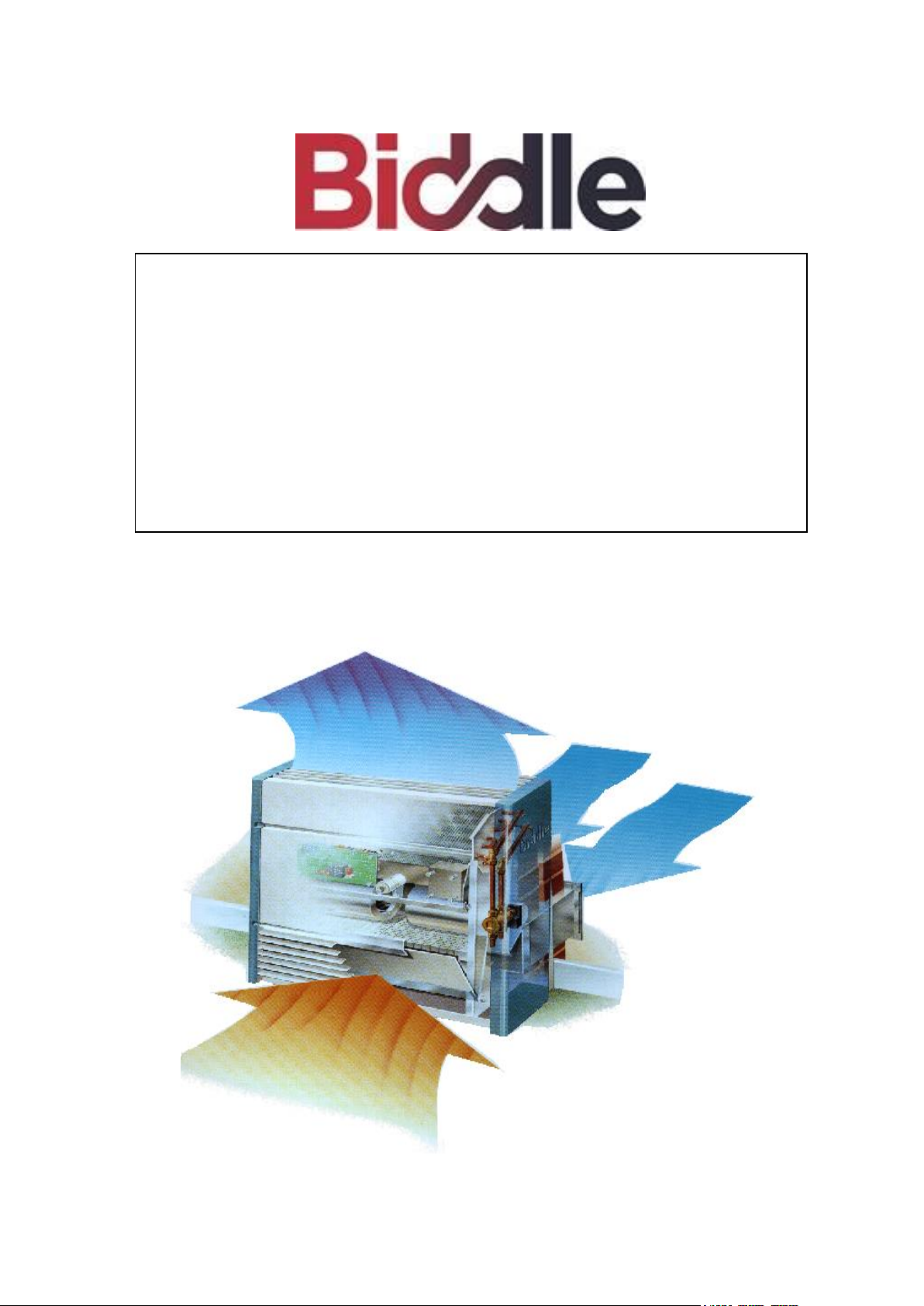
Innovair Size 3 & Innovair School
Intelligent Fan Convectors
INSTALLATION, OPERATION & MAINTENANCE
INSTRUCTIONS
Version 2.1
Page 2

CONTENTS
Section 1. GENERAL INFORMATION
Important……………………………………………..………… Page 3
Dimensions & Weights……………………………………….. Page 3
Ductwork Connection Options (Chassis Units)…………….. Page 4
Fixing Centres & Pipework Entry Points…………………….. Page 5
Section 2. INSTALLATION – (Mechanical)
Stages Involved CASED UNITS…………………………….. Pages 6 to 8
Stages Involved CHASSIS UNITS………………………….. Pages 9 to 11
Section 3. INSTALLATION – (Electrical)
Connecting the Unit to Mains Power………………………… Page 12
Customer Connection Centre Diagram – AC units…………. Page 13
Customer Connection Centre Diagram – EC units…………. Page 14
Connecting the Remote Control Pad to the Unit…………….. Page 15
Connecting Units as Master/Slave ……..……………...…….. Page 15
Connecting the Unit to a BMS………………………………. Page 16
Connecting the Unit to a Timer Clock or PIR………………. Page 16
Connecting the Unit to an Extract System……..……………. Page 17
Connecting the Unit to a Biddle CO2 Sensor……………….. Page 18
Section 4. CONTROL & OPERATION
Standard Controls and other Options………………………… Page 19
Control Pad – Manual Operation…………………………….. Pages 20 & 21
Control Pad – Auto & BMS Operation……………………….. Pages 22
Section 5. MAINTENANCE
Access Panel……………………………………………….… Page 23
End Panels…………………………………………………… Page 23
Filter………………………………………………………… Page 23
Fans & Motors………………………………………………. Page 23
Heating Coil…………………………………………………. Page 23
Damper & Actuator…………………………………………. Page 23
Casing……………………………………………………….. Page 23
Page 2 v2.1
Page 3
Section 1. GENERAL INFORMATION
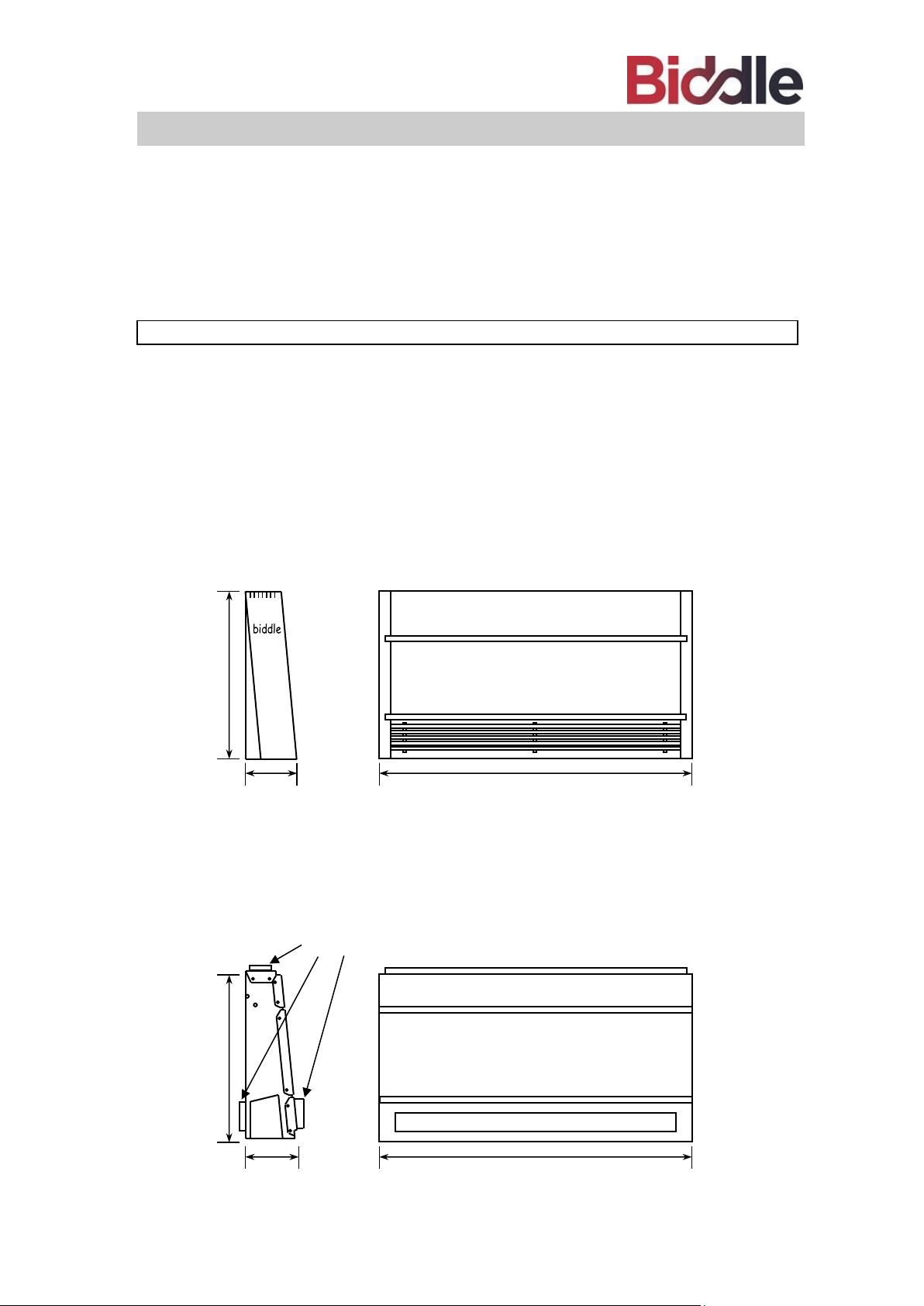
Dimension
Cased Unit
Recessed Unit
Width
1808 mm
1764 mm max over fixings
Depth
330 mm
324 mm
Height
860 mm
859 mm
Weight
95 kg
91 kg
Width
Height
Width
Depth
Height
Depth
IMPORTANT!
IT IS ESSENTIAL TO ISOLATE THE UNIT FROM THE ELECTRICAL SUPPLY AND THE
CONTROL CIRCUIT POWER SUPPLY BEFORE CARRYING OUT ANY MAINTENANCE,
AND TO ENSURE THAT THE POWER CANNOT BE ACCIDENTLY RESTORED BY
UNAUTHORISED PERSONNEL.
DIMENSIONS & WEIGHTS
CASED UNITS (with fixed grilles) Figure 1a
RECESSED/ CHASSIS UNITS (with loose grilles) Figure 1b
Fixed spigots
Page 3 v2.1
Page 4
Section 1. GENERAL INFORMATION - continued
1284
24.5
207 27.5
4 x 250
PITCHES
5 x 200 DIA
SPIGOTS
131
37
1695
100-160
211.5
10
4 x 310
Pitches
208.5
121
=
=
5 x 200 DIA
1693
207
100
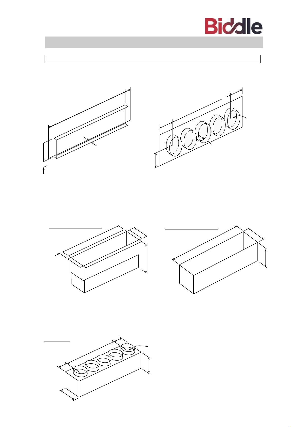
TELESCOPIC DUCT SECTION
(SPIGOT) EXTENSION PIECE
PLENUM BOX
Use where an adjustable short duct section is
required to connect to the Biddle linear grille.
The telescopic duct is sized to accept the
standard Biddle Air grille.
Use where the discharge or return air will
connect to the Biddle linear grille but the
connection needs to be longer than 160mm.
The spigot extention piece allows
connection of ducting (by others) of a cross section suitable for the Biddle grille.
Purpose made plenum box for
connection of circular ducting. Blanking
caps are available for spigots not used
but only one or two should be blanked at
any one time. Specially sized spigots are
available. Contact the sales office.
Figure 1c
Figure 1d (optional – cannot
be used with attenuator)
Figure 1e
Figure 1f
Figure 1g
DUCT / SPIGOT CONNECTIONS
FRESH AIR INLET CONNECTIONS 2 Standard Styles
(Back or Base position)
DISCHARGE & RETURN AIR CONNECTIONS 3 Optional
Styles
(On Recessed / Chassis units only)
Page 4 v2.1
Spigots
37 mm Deep
Page 5
Section 1. GENERAL INFORMATION - continued
BASE OF UNIT
31
72
95
80
91
31
72
95
80
91
BACK OF UNIT
FRONT OF UNIT
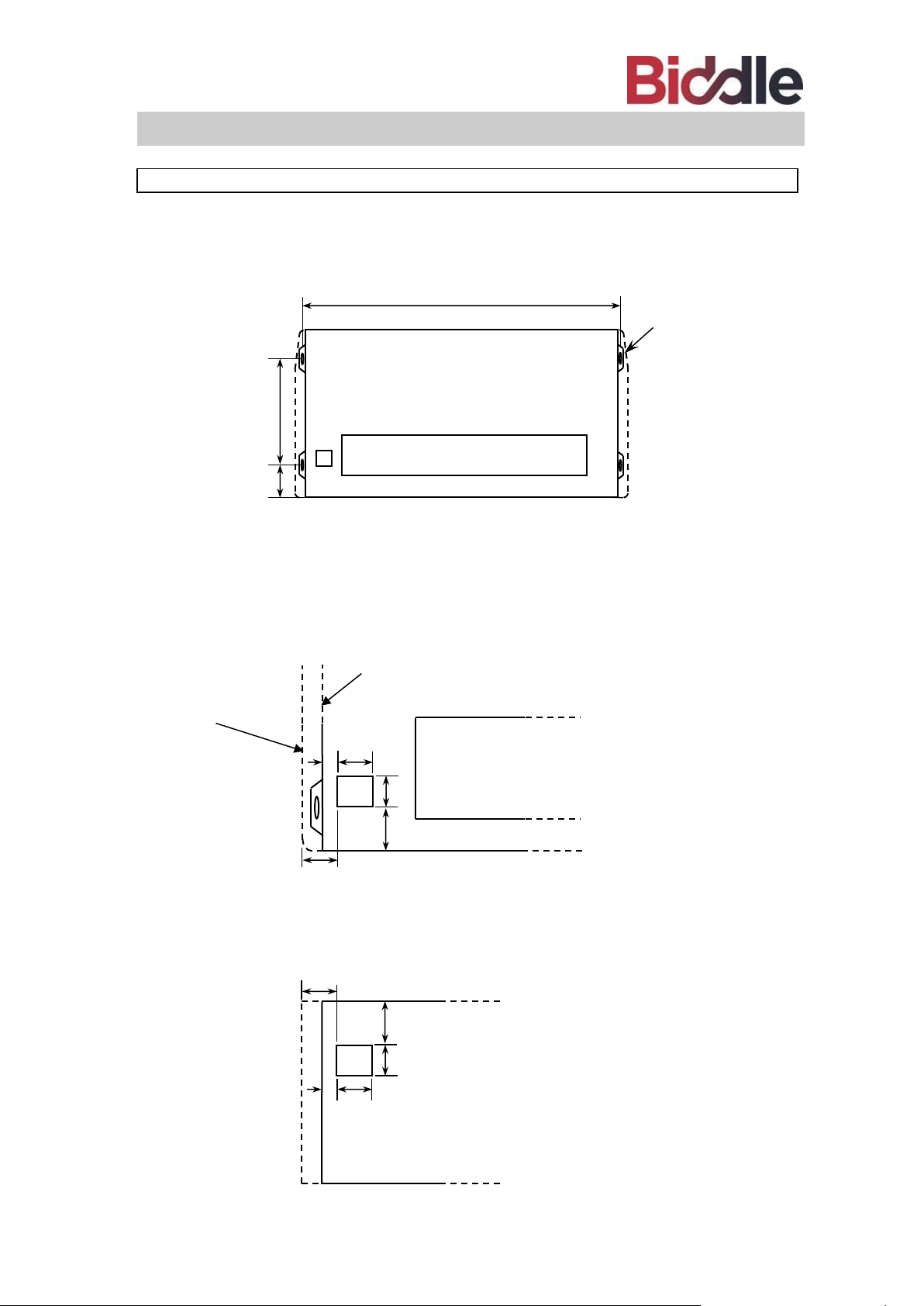
4 off slots 10 x 30.
For M8 Bolts or
threaded bar.
TOP OF UNIT
BASE OF UNIT
1716
Figure 2a
Figure 2b
Figure 2c
FIXING POSITIONS / PIPEWORK ENTRY
FIXING CENTRES (Viewed from back of unit)
Dimensions in mm
PIPEWORK APERTURE (Viewed from back of unit – RHS Unit shown)
Dimensions in mm
Denotes edge of
Chassis unit
Denotes edge of
Cased unit
ALTERNATIVE PIPEWORK APERTURE (Viewed from base of unit – RHS Unit shown)
Dimensions in mm
Page 5 v2.1
Page 6
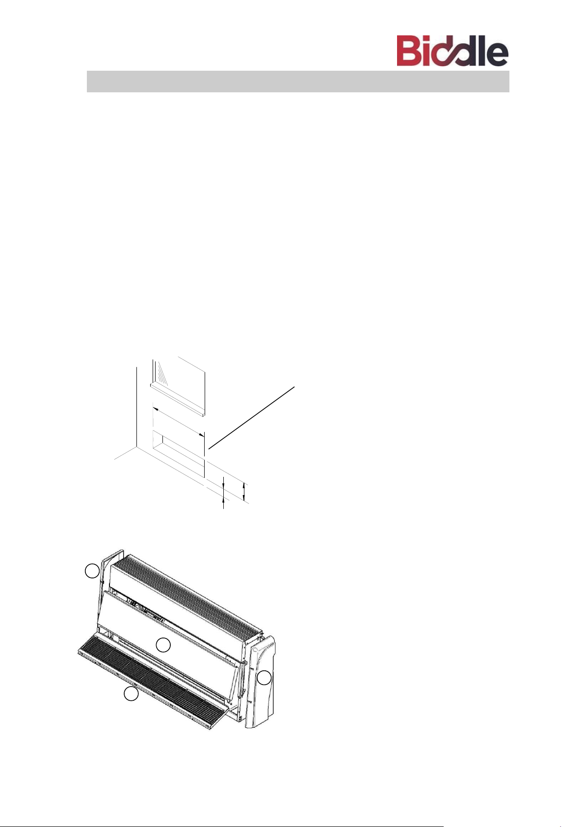
Section 2. INSTALLATION – Typical Cased Unit
3
2
1
3
Minimum Aperture Dimensions
Innovair Size 3 & Innovair School Only
A = 1305 mm
B = 225 mm
C = 25 mm (Dimension when Innovair is sitting
directly on floor)
A
C
B
The Innovair Units will be delivered to site preassembled. All metal panels will be attached. The
moulded end panels will be supplied loose.
Remove casing in following order:
1. Remove recirc grille access panel. Undo 2 screws on
bottom edge. Pull bottom edge forward and lower panel
away from unit.
2. Remove front access panel. Undo 2 screws on bottom
edge and lower panel to clear retaining lip at top.
3. Remove plastic end panels. Undo 3 screws on front
edge and 1 screw at top rear. (This only needs to be
done if unit already installed and access is required for
venting coil (RHS*) or damper motor access (LHS*).
*Handings given for RH unit. Opposite for LH.
Figure 4
Figure 3
IMPORTANT.
PLEASE READ ALL SECTIONS BEFORE PROCEEDING WITH INSTALLATION
STAGES INVOLVED
Figures 3 to 7 show how the unit is dismantled, connected to the fresh air supply
and re-assembled. See additional sections within the installation instructions for
connection to electrical supply and controls.
Take care not to damage components and accessories when handling them.
Before installing the unit check that there will be adequate access space for
maintenance (recommended 300mm each side).
The approximate amount of time needed to install the unit is half a day, plus the
time needed to make the fresh air duct hole in the building.
Remember! that in order to get heating on water heated units, all the air must be
bled from the system including the coil in the unit.
FRESH AIR APERTURE THROUGH OUTSIDE WALL
CASED UNIT - DISMANTLING
Page 6 v2.1
Page 7
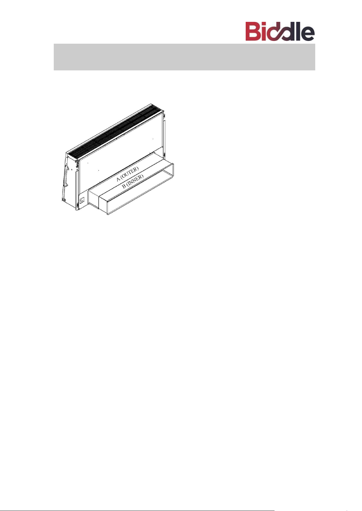
Section 2. INSTALLATION – Typical Cased Unit
Figure 5
Continued
FIXING CASED UNIT TO OUTSIDE WALL & ATTACHING WALL SLEEVE/ATTENTUATOR
View on rear of unit
1. Before fixing the unit to the external
wall. Attach the outer section (Part A) of
the telescopic wall sleeve/attenuator to
the fixed spigot on the back (or rear) of
the Innovair unit. The sleeve should be
attached using self tapping screws No.8
or duct tape.
2. Offer the unit up to the fresh air
aperture (already cut into the external
wall) making sure that the outer section
(Part A) freely slides inside of the wall aperture. Fix the unit to the wall via 4 off
fixing lugs with suitable screws.
3. From outside, slide the inner section of the telescopic wall sleeve/attenuator
(Part B, flange on outside of wall) as far into part A as the wall thickness will allow.
Seal the joint inside of the two halves of the sleeve using ‘duct tape’ or similar.
4. Before fitting the external weatherproof grille, un-wind the cable of the fresh air
sensor, located within the Innovair unit (fresh air aperture) and position the sensor
just inside of the external weatherproof grille. Failure to position the sensor behind
the grille may prevent accurate operation of the unit.
5. Fix the weatherproof grille (usually supplied by others) to the outside wall.
6. Feed the water pipework (if applicable) through either of the two appertures
provided in the back or base of the unit casing. Connect pipework to the 2 open
ports of the control valve. Ensure flow and return pipework corresponds to the
flow and returns on the valve.
7. Ensure that both pipework and heating coil is fully vented.
SEE PAGE 13 FOR ELECTRICAL CONNECTIONS.
Page 7 v2.1
Page 8
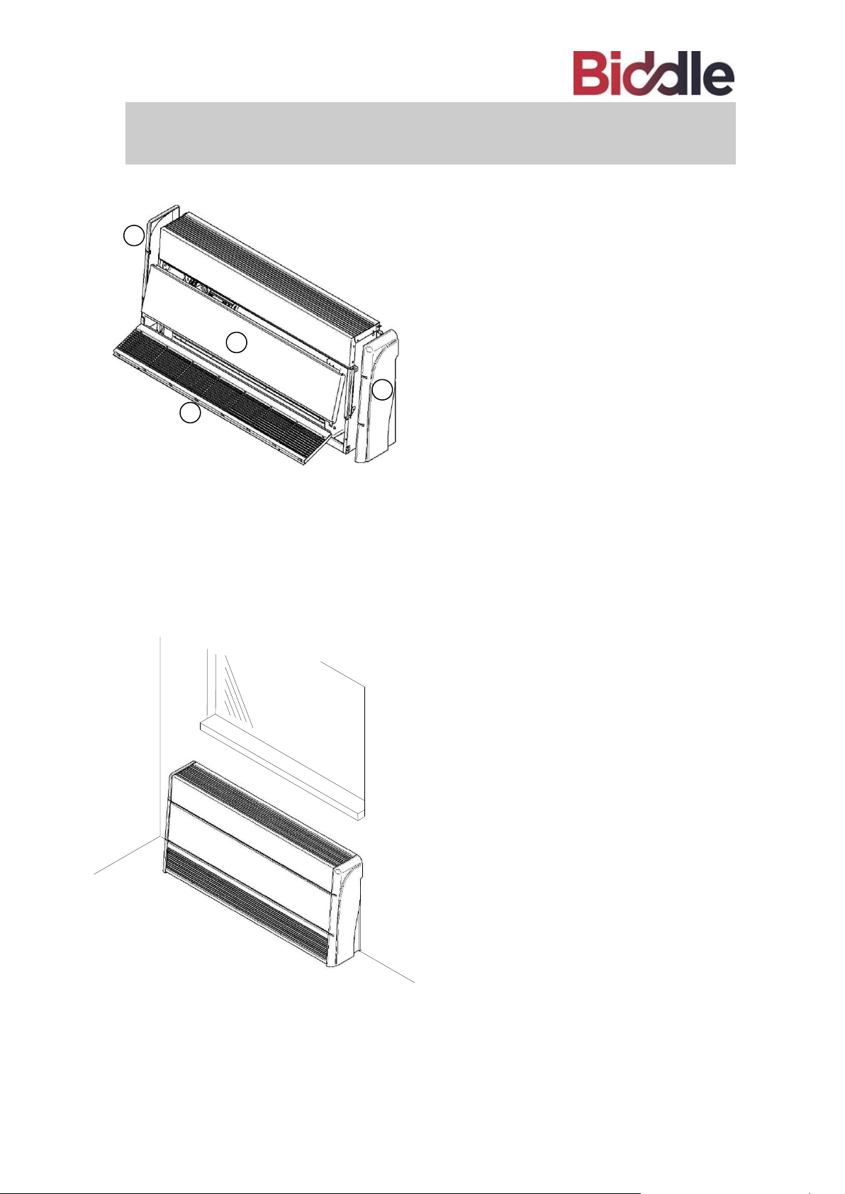
Section 2. INSTALLATION – Typical Cased Unit
Unit installed and ready to operate.
Make sure all debris is removed from the unit and
surrounding area.
3 2 1
3
Assemble casing in following order:
1. Attach plastic end panels using screws on front
edge.
2. Attach front access panel. Locate lip on top edge of
panel into retailing channel on upper casing (A)
Push home access panel into channel and fix using
two screws supplied.
3. Attach recirc grille access panel. Locate top edge of
recirc grille access panel beneath bottom edge of
main access panel. Push home grille panel in an
upward direction at the same time turning the panel
vertically. Fix using the two screws provided on
bottom edge.
Figure 6
Figure 7
Continued
CASED UNIT - ASSEMBLING
COMPLETED ASSEMBLY CASED UNITS
Page 8 v2.1
Page 9
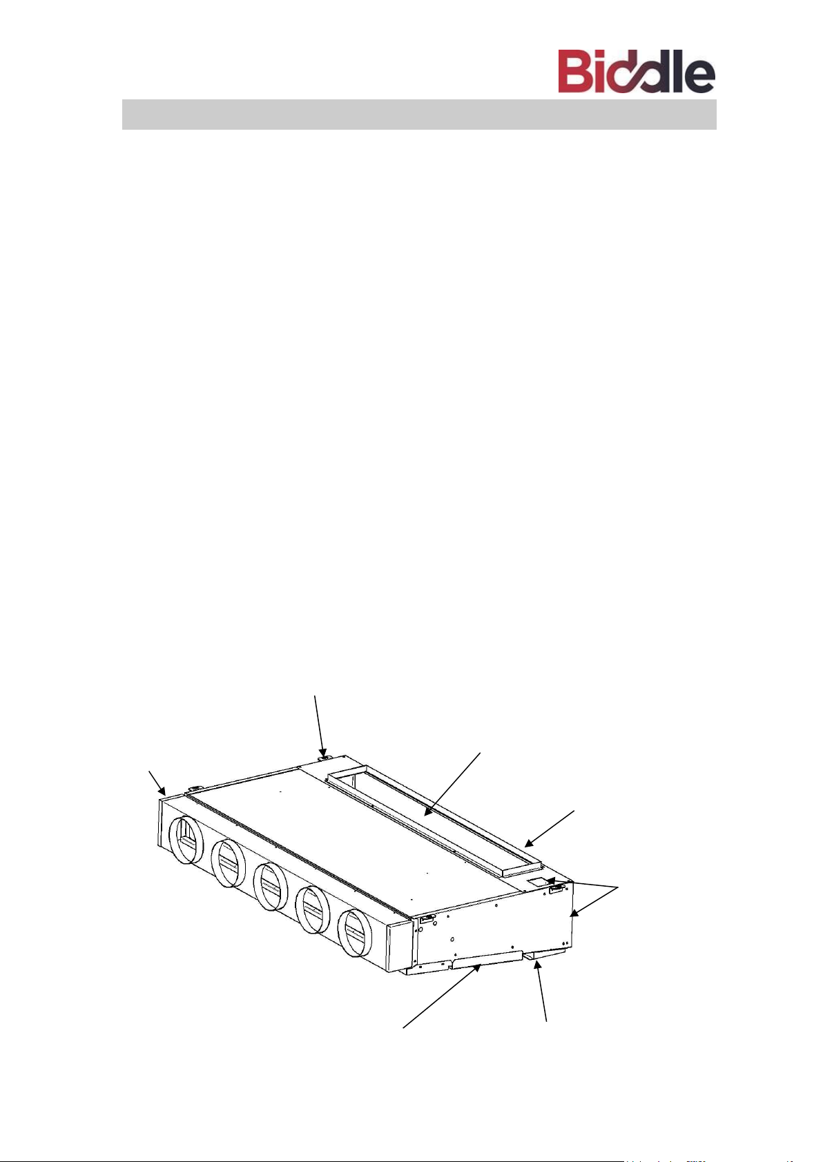
Section 2. INSTALLATION – Typical Chassis Unit
Optional
Plenum Box
c/w circular spigots
(attached to fixed discharge
spigot)
Innovair Base Unit
4 off Fixing Lugs
Fresh Air Fixed Spigot – Shown on
‘Back’
Alternative FA
position on ‘Base’ of
unit
Pipe entry apertures
On both ‘Back’ &
‘Base’. (RH unit shown)
Return Air Fixed Spigot
Main Access Panel
Figure 8
IMPORTANT.
PLEASE READ ALL SECTIONS BEFORE PROCEEDING WITH INSTALLATION
STAGES INVOLVED
Figure 8 shows a typical chassis type unit suitable for mounting within a ceiling
void. The following notes give instruction on how the unit is dismantled,
connected to the fresh air, return air and supply air ducts and re-assembled. See
additional sections within the installation instructions for connection to electrical
supply and controls.
Most components used in the manufacture of the chassis unit are the same as
the cased unit. The main exception being that there are no moulded end panels
and that the return air & discharge apertures have fixed spigots (not grilles).
Care should be taken not to damage components and accessories when
handling them.
Before installing the unit check that there will be adequate access space for
maintenance (recommended 300mm each side).
Remember! that in order to get heating on water heated units, all the air must be
bled from the system including the coil in the unit.
TYPICAL CEILING VOID MOUNTED CHASSIS UNIT.
Page 9 v2.1
Page 10

Section 2. INSTALLATION – Typical Chassis Unit –
cont.
CHASSIS UNIT – DISMANTLING.
The Innovair Units will be delivered to site pre-assembled with all panels
attached. The various duct connections (Telescopic, Spigot Extension & Plenum
Box) will be loose and will require attaching to the relative fixed spigot on site.
It will only be necessary to remove the main access panel to enable the unit to
be installed.
To remove the access panel undo the 2 retaining screws and slide the panel
towards the return air spigot to release the panels retaining lip from a support
channel.
FIXING CHASSIS UNIT & ATTACHING EXTERNAL DUCTING.
Locate and fix the Innovair unit into position using the 4 fixing points provided.
(10 x 30mm slots). Fix using suitable screws, bolts or threaded drop rods.
Fresh Air Connection.
If fresh air connection is directly against a double skin outside wall:
Use the telescopic wall sleeve/attenuator provided by Biddle (see Figure 5 and
associated notes on page 7)
If fresh air connection is remote from Innovair unit:
Fix fresh air duct (by others) directly to the fixed spigot provided at either the
back or base position.
Before fitting the external weatherproof grille, un-wind the cable of the fresh air
sensor, located within the Innovair unit (fresh air apperture) and position the
sensor just inside of the outside face of the wall. This may involve extending the
sensor cable if the ducting is sizable.
Fix the weatherproof grille (usually supplied by others) to the outside wall.
Return Air Connection.
It is not necessary to have a ducted return air if the ceiling void is being used as
a return air plenum. However if a solid ducted connection is required then there
are 4 options available. Using the fixed spigot supplied as standard with the unit
or one of the 3 connection options shown on page 4 of the manual.
Option 1. Fixed spigot.
Connect suitable sized ducting (by others) directly onto the fixed spigot
supplied with the unit.
Option 2. Telescopic duct section by Biddle.
Attach outer section to return air spigot using screws provided, the inner section
of the duct with external bends fits against the rear of builderwork apperture.
Adjustment of the duct is between 100mm and 160mm.
Page 10 v2.1
Page 11

Option 3. Spigot Extension Piece by Biddle.
Attach to the unit using screws provided. If the ducting needs to be longer than
100mm, attach suitable ducting (by others) to the extention piece.
Option 4. Discharge Plenum by Biddle.
Attach to the unit using screws provided. Allows connection of circular ducting.
Page 11 v2.1
Page 12

Section 2. INSTALLATION – Typical Chassis Unit –
cont.
Supply Air Connection.
Chassis units should always have a ducted discharge to the outlet grille to
prevent ‘short circuiting’ of the conditioned air back into the unit. The
connection options are the same as the return air with 4 options available. Using
the fixed spigot supplied as standard with the unit or one of the 3 connection
options shown on page 4 of the manual.
Option 1. Fixed spigot.
Connect suitable sized ducting (by others) directly onto the fixed spigot
supplied with the unit.
Option 2. Telescopic duct section by Biddle.
Attach outer section to return air spigot using screws provided, the inner section
of the duct with external bends fits against the rear of builderwork apperture.
Adjustment of the duct is between 100mm and 160mm.
Option 3. Spigot Extension Piece by Biddle.
Attach to the unit using screws provided. If the ducting needs to be longer than
100mm, attach suitable ducting (by others) to the extention piece.
Option 4. Discharge Plenum by Biddle.
Attach to the unit using screws provided. Allows connection of circular ducting.
Position Of CO2 Sensor.
The chassis Innovair unit is supplied with a factory wired CO2 sensor located
within the return air void. During installation the CO2 sensor need to be removed
from the Innovair unit and located aboe the nearest ceiling return air grille to
enable accurate measurement of the CO2 level within the room. The CO2
sensor is provided with a 3m long flying lead.
Page 12 v2.1
Page 13
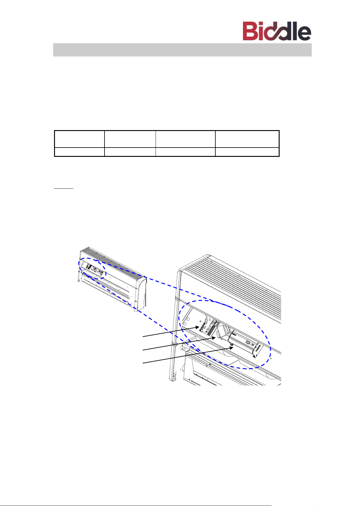
Section 3. ELECTRICAL CONNECTIONS
Mains Supply
Running Current
(Amps)
Starting Current
(Amps)
Water Heated
230v/1/50Hz
1.5
4.5
Transformer
Terminal Block
IQeco
CONNECTING THE UNIT TO MAINS POWER
Installation cable sizing should always be done by a qualified electrician in
accordance with current regulations.
The suggested mains supply cables for Innovair are as follows:
water heated units, 3-core mains cable (Cu/PVC/PVC) size 1mm
The electric’s control panel is located directly behind the main access panel.
Water - Thread the mains power cable through the cable gland on the LHS (RHS
on LH units). Wire to terminals L N E on the terminal block located at the LH end
of the electric control panel (RH end on LH units). See figure 9. Use cable ties
provided to secure cables and ensure they are not trapped when panel is
replaced.
Figure 9
2
The connection of on site wiring should be restricted to the designated
connection points, i.e. the provided terminal block etc. No electrical
connection should be made directly with the IQeco controller. Always read the
wiring diagram.
Page 13 v2.1
Page 14
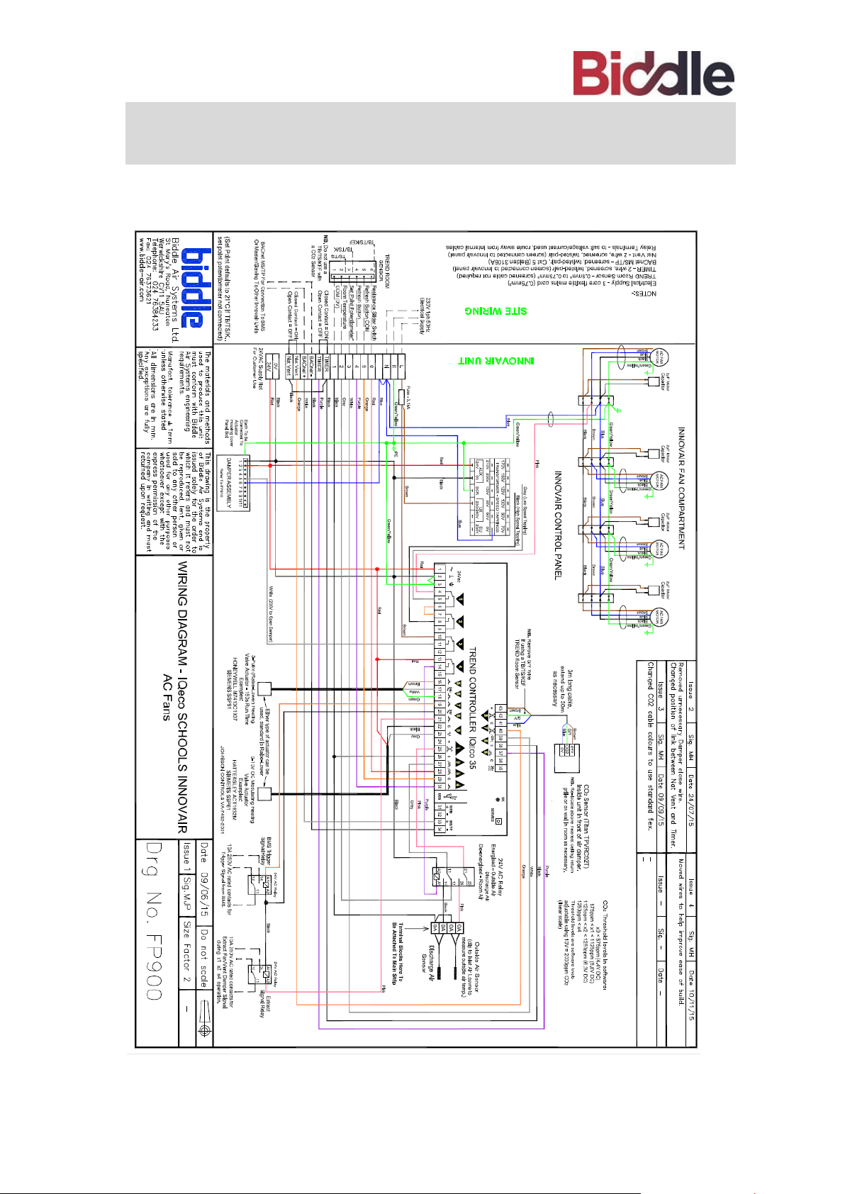
Section 3. TYPICAL WIRING DIAGRAM
AC WATER HEATED UNIT
TYPICAL WIRING DIAGRAM – (Check with the supplied diagram that comes
with the unit).
Page 14 v2.1
Page 15
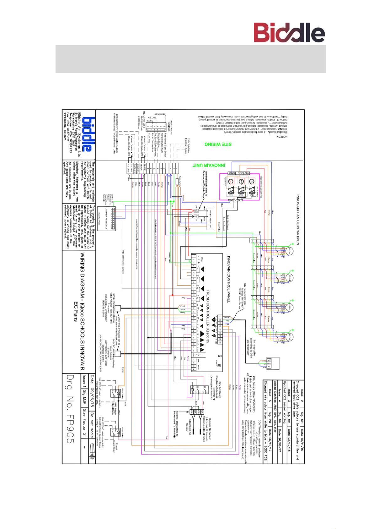
Section 3. TYPICAL WIRING DIAGRAM
EC WATER HEATED UNIT
TYPICAL WIRING DIAGRAM – (Check with the supplied diagram that comes
with the unit).
Page 15 v2.1
Page 16
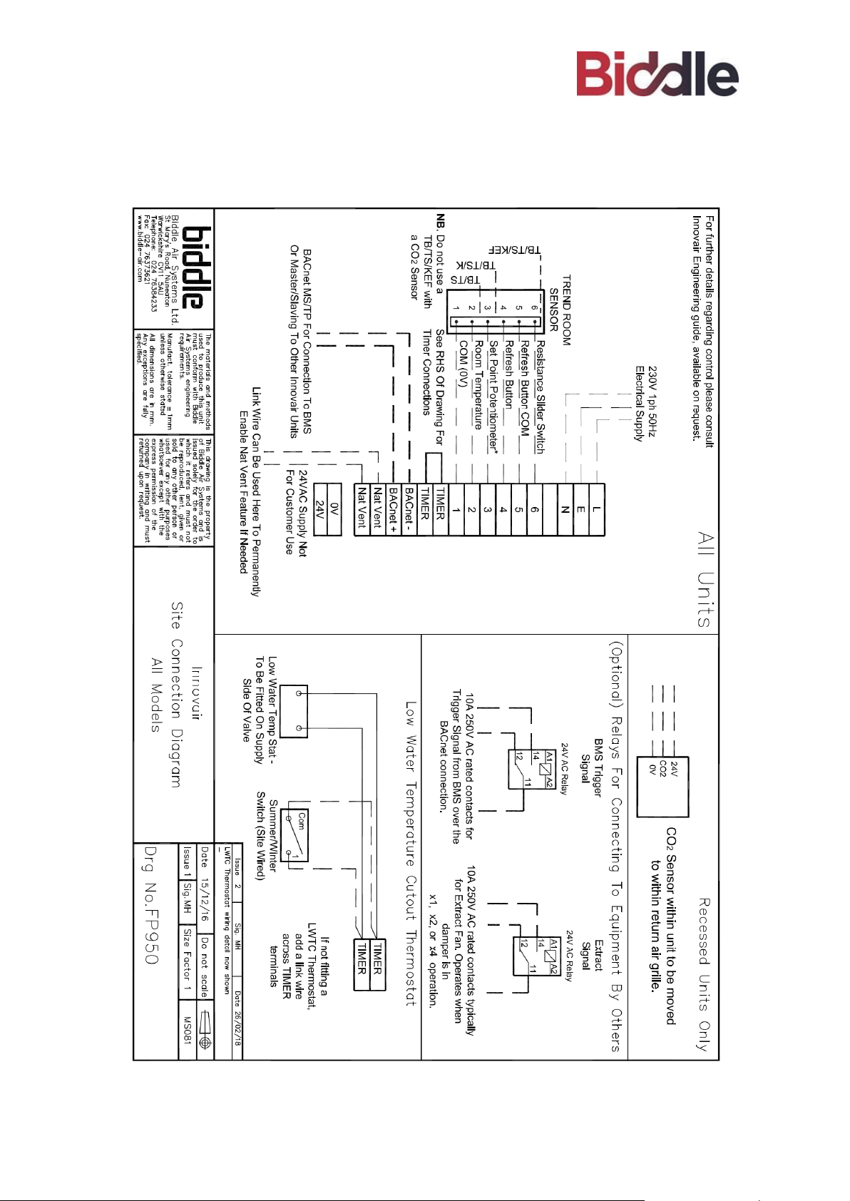
Section 3. ELECTRICAL CONNECTIONS continued
Page 16 v2.1
Page 17

CONNECTING THE REMOTE CONTROL PAD TO THE UNIT
The remote room controller supplied with the unit should be connected to the
designated connection points on the provided terminal block on the control
panel using Non Screened 16/0.2mm (0.5mm2) cable. Cable ties and cable
glands are provided to secure cables. The number of cable cores will depend on
the type of room controller as detailed below.
THIS CONNECTION IS VOLTAGE FREE AND SHOULD NOT BE CONNECTED TO ANY
OTHER VOLTAGE SOURCE.
The Model TB/TS-BIDDLE wall mounted controller for temperature sensing only,
requires 2 cores connected to terminals numbered 1 – 2.
The Model TB/TS/K-BIDDLE for manual heating & automatic / no ventilation
adjustment requires 3 cores connected to terminals 1, 2 & 3 only.
Cables must be connected to both the terminal block located inside the unit
control panel and the remote control pad using the identically numbered
terminal.
See the unit wiring diagrams (page 13/14) and installation instructions supplied
with the control pad for details.
Page 17 v2.1
Page 18
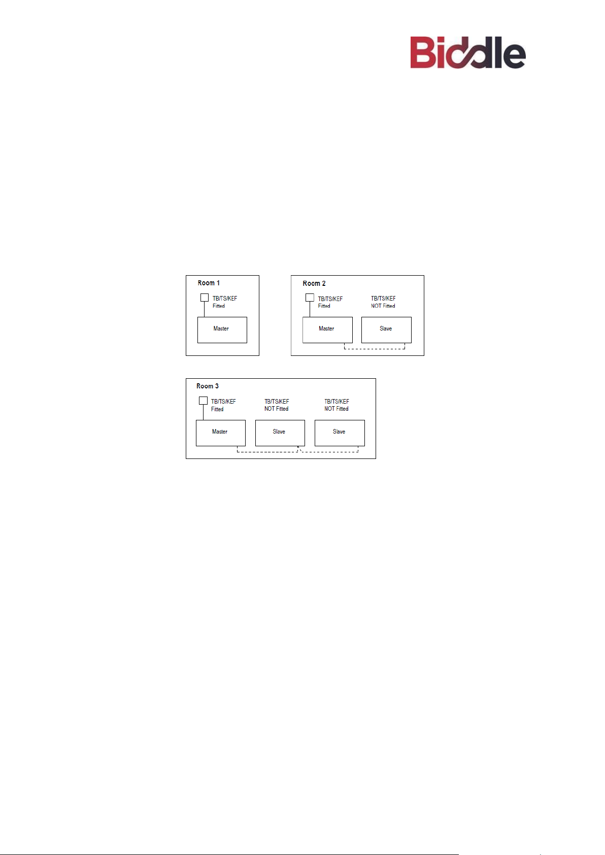
Connecting Units As Master/Slave
Connect the remote control pad to the unit designated as the Master unit as
described above (this unit will automatically detect it when powered up and
configure as the master). Units without a control pad will assume a salve status
when no room pad can be found.
Master and slave units should be connected via a Belden 9841 (or equivalent)
cable to the terminals labelled BACnet. Please daisy chain all positive terminals
together and all negatives together.
Do not connect units to a BMS network or another master/slave setup using this
configuration. Up to 10 slaves can be linked to a single master.
Page 18 v2.1
Page 19

Section 3. ELECTRICAL CONNECTIONS continued
CONNECTING THE UNIT TO A BMS
Please refer to the Innovair Engineering Guide for details on how the unit can be
connected to a BMS network.
CONNECTING THE UNIT TO A TIMER CLOCK OR P.I.R. Sensor
Unless using a BMS (or other supervisory system) to enable the unit, the unit is
controlled by linking across the Timer terminals on the main terminal strip in the
unit where linked = ‘on/occupied’.
Connections should be made on site to either a PIR, low water temperature stat
(used in conjunction with a Summer/Winter switch) or other volt free contacts.
When connecting a low water stat, follow the below instructions. You should
include a summer/winter switch in the design to allow the unit to operate in
Summer when there is no hot water available.
Using the typically supplied Siemens RAM1 – connect terminals 1 and 3 to
the Timer connections (note polarity doesn’t matter).
Connect the summer/winter switch in parallel across the T4. It is
recommended that in public spaces, this switch is located discretely so it
isn’t tampered with.
Fix the RAM1 to the supply side of the pipework - not the unit side.
Tidy all wiring up
When connecting a PIR sensor:
Please refer to the PIR sensor manufacturer’s documentation – the
contacts MUST be volt free.
Page 19 v2.1
Page 20

Section 3. ELECTRICAL CONNECTIONS continued
CONNECTING THE UNIT TO AN EXTRACT & OR SUPPLY FAN
SYSTEM (Single phase supply & running current no greater than
8amps)
Where an extract fan or additional supply fan is required in the system, the
on/off control of this device can be enabled via the Innovair units. This is
achieved using the extract fan relay controlled via the IQeco. The relay will
stay energised for as long as the damper is cycling – note that it won’t just
energise when the damper is open. The relay is provided mounted and wired
inside of the Innovair control panel for connection on site using 3 core mains
cable size 1.0mm2 cable.
Important:
The maximum electrical ratings for the external device (i.e. Extract Fan) are
as follows:
8A 250V AC1
3A 250V AC11
8A 24V DC1
INTEGRAL CO2 SENSOR
The Biddle supplied CO2 sensor comes fitted to the front of the unit behind the
recirculation inlet. For installations where the unit is to be exposed to the room
air, this is sufficient. However for installations where the unit isn’t directly
exposed (such as a recessed unit above a suspended ceiling) the sensor is
supplied on a 3m flexible lead to allow for remote positioning in the space’s
air.
THE CO2 SENSOR CONNECTIONS ARE VOLTAGE FREE AND SHOULD NOT BE
CONNECTED TO ANY OTHER VOLTAGE SOURCE.
Page 20 v2.1
Page 21

Section 4. CONTROL & OPERATION
SUMMARY OF STANDARD CONTROLS AND OTHER CONTROL
OPTIONS
1. Manual / Stand Alone Type
Standard External Controls Hardware (Supplied by Biddle)
1a. Remote Wall Mounted Controller Ref: TB/TS/K-BIDDLE
Manual On/Off Control
Manual Room Temperature Control
Additional Control Functions
1b. Remote On/Off Control Via. Volt Free Contacts
ie. Timer, BMS or PIR
1c. Extract Control Via. Additional Relay Circuit
1d. Master / Slave group control via.BACnet Terminal Connection
2. Manual Heat / Automatic Ventilation
Standard External Controls Hardware (Supplied by Biddle)
2a. Remote Wall Mounted Controller Ref: TB/TS/K-BIDDLE
Manual Room Temperature Control Only
2b Remote Wall Mounted CO2 Sensor (Supplied by Biddle to order)
Automatic control of ventilation levels based on CO2
concentration.
IMPORTANT: With this arrangement there is no provision for Manual On/Off
Control. This must be done via. a remote device ie. Timer or BMS enabling
signal.
Additional Control Options Available
2c. Extract Control Via. Additional Relay Circuit (Not Standard Supply)
2d. Master / Slave group control via. BACnet Terminal Connection
(Supplied as standard)
3. Automatic BMS Control.
Standard External Controls Hardware (Supplied by Biddle)
3a. Remote Wall Mounted Controller Ref: TB/TS/K-BIDDLE
Manual Room Temperature Control Only
Additional Control Options Available
3b. Automatic control of ventilation levels based on CO
concentration Via CO2 sensor (Supplied and fitted by others, wired
through the BMS).
3c PIR Occupancy sensor for On/Off Control (Supplied and fitted by
others, wired through the BMS).
3d. Master / Slave group control Via. Direct Connection to BMS
2
Page 21 v2.1
Page 22

Page 22 v2.1
Page 23
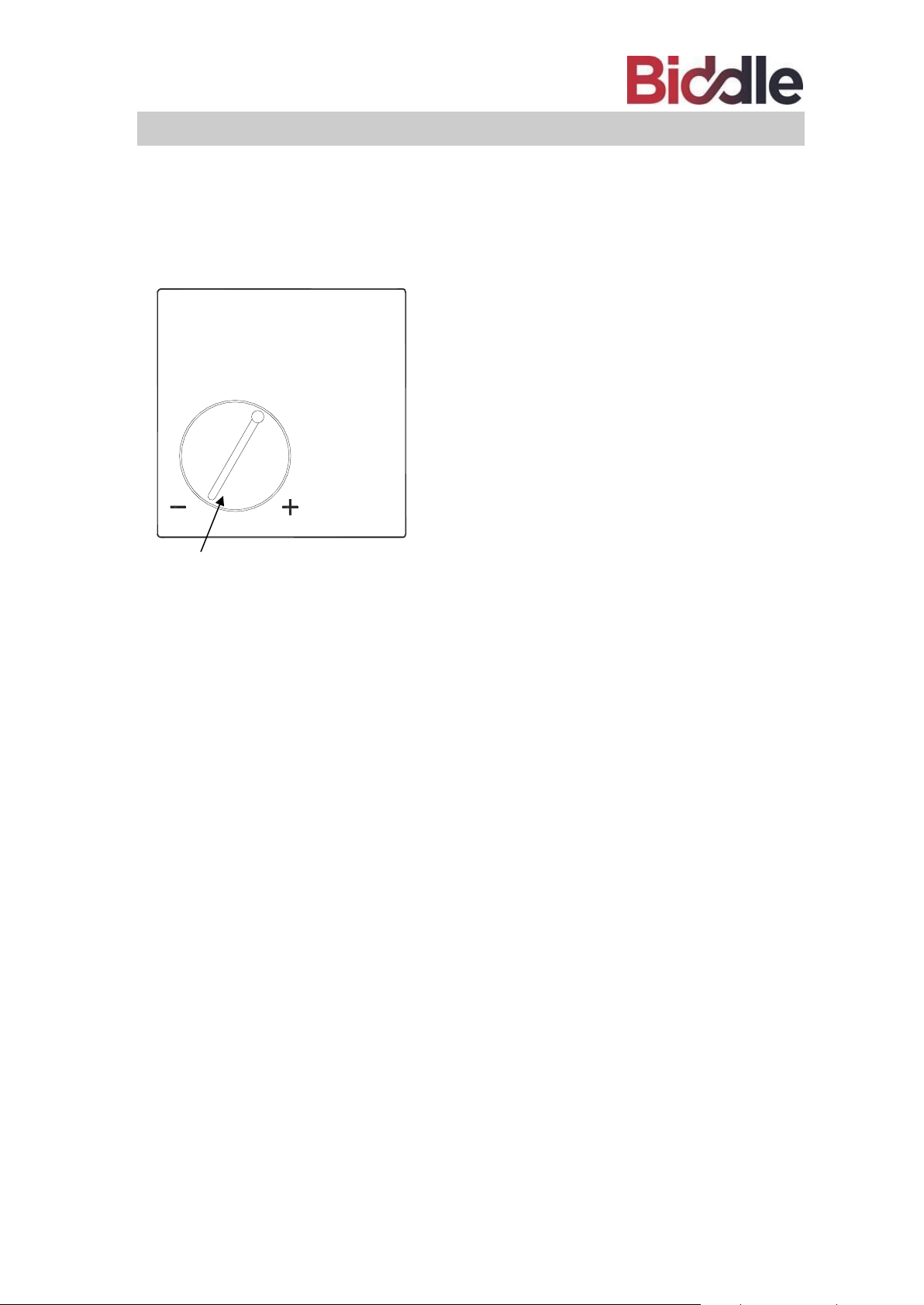
Section 4. OPERATION – Automatic Ventilation
°C
Set point adjuster (Shown at approx 21.50C)
Figure 12
Room Control type: TB/TS/K-BIDDLE for manual Temperature & Automatic
Ventilation.
Also incorporates a room temperature sensor
DO NOT SWITCH UNIT OFF AT THE MAINS except in times of emergency
Unit Functionality:
In this format of operation the unit is effectively switched ON or OFF by the use
of an external timer, PIR sensor or BMS. See individual connection information.
All ventilation rates are controlled automatically and there is no manual
control. A CO2 sensor is required in the unit with this form of control. This limits
the quantity of fresh air to just that required for the occupancy of the room for
increased energy efficiency. The Sensor is supplied built into the units and
should be removed and mounted remotely on chassis units.
See section headed ‘Connection to CO2 Sensor’ for more information.
Manual adjustment of Room temperature is controlled by the set-point
adjuster, which can be rotated between the 18°C and the 24°C settings.
BMS control can also be used to remotely re-scale the minimum and
maximum set point positions (e.g. 19°C min / 23°C max) for increased energy
efficiency.
The unit will operate in either Normal ‘occupied’ operating mode or
‘Unoccupied’ set-back mode, exactly as the Manual / Stand Alone unit
does. In Unoccupied set-back mode the unit operates to satisfy the set
back temperature or ‘night time cooling requirement only.
Page 23 v2.1
Page 24

Page 24 v2.1
Page 25

Section 5. MAINTENANCE
TOOLS REQUIRED:-
7mm A/F nut spanner
Pozidrive 2pt Screwdriver
FILTER
Filters are of the ‘Replaceable Cartridge Type’ with cardboard frame. The filters
are located behind the main access panels (4 screws) and retained with a metal
channel (2 Screws).
A vacuum cleaner or gentle beating may be used to clean the filter. Badly
impregnated filters should be replaced.
The period between cleaning is dependent on operating conditions. In a very
dirty atmosphere the filter will require frequent cleaning (maybe every few weeks)
whereas in a clean environment it may only be necessary every few months.
ACCESS PANEL
To remove the main access panel it is first necessary to remove the re-circulation
grille. The grille and its frame are held in place by 2 off M5 hexagonal headed
screws. Once the grille is removed the main access panel retaining screws, also
2 off M5 hexagonal headed screws are exposed allowing the access panel to be
removed.(Refer to figure 4).
END PANELS
Each plastic end panel is located along its rear edge by a vertical channel and
then secured by five M5 hexagonal head screws. Three screws at the front and
two at the top rear. (refer to figure 4).
FANS & MOTORS
Providing the filter is regularly cleaned the fans and motors will require no
attention. They can be accessed however by removing the re-circulation grille
access panel and the main access panel. Clean using a soft brush and vacuum
cleaner.
HEATING COIL
Providing the filter is regularly cleaned the heating coil will require little or no
attention.
However if the filter is allowed to get very dirty some dust will percolate through
and become entrained in the coil. In this case it can be cleaned by removing
the front access panel, the discharge grille, the discharge access panel and the
coil access panel and applying a jet of air to the air leaving face.
DAMPER AND ACTUATOR
The damper requires no maintenance, other than to brush clean occasionally.
Located on the left hand side of the unit the damper actuator requires no
maintenance and should not be removed from its mounting panel.
CASING
The interior of the unit should be cleaned occasionally with a soft brush and a
vacuum cleaner.
Page 25 v2.1
Page 26

On cased units periodically check that the paint is in good condition and repair
when necessary.
Page 26 v2.1
Page 27

Biddle Air Systems Limited
St. Mary’s Road, Nuneaton, Warwickshire CV11 5AU
Tel: +44 (0) 2476 384233 Fax: +44 (0) 2476 373621
Page 27 v2.1
 Loading...