

Page 1
Q
Manual
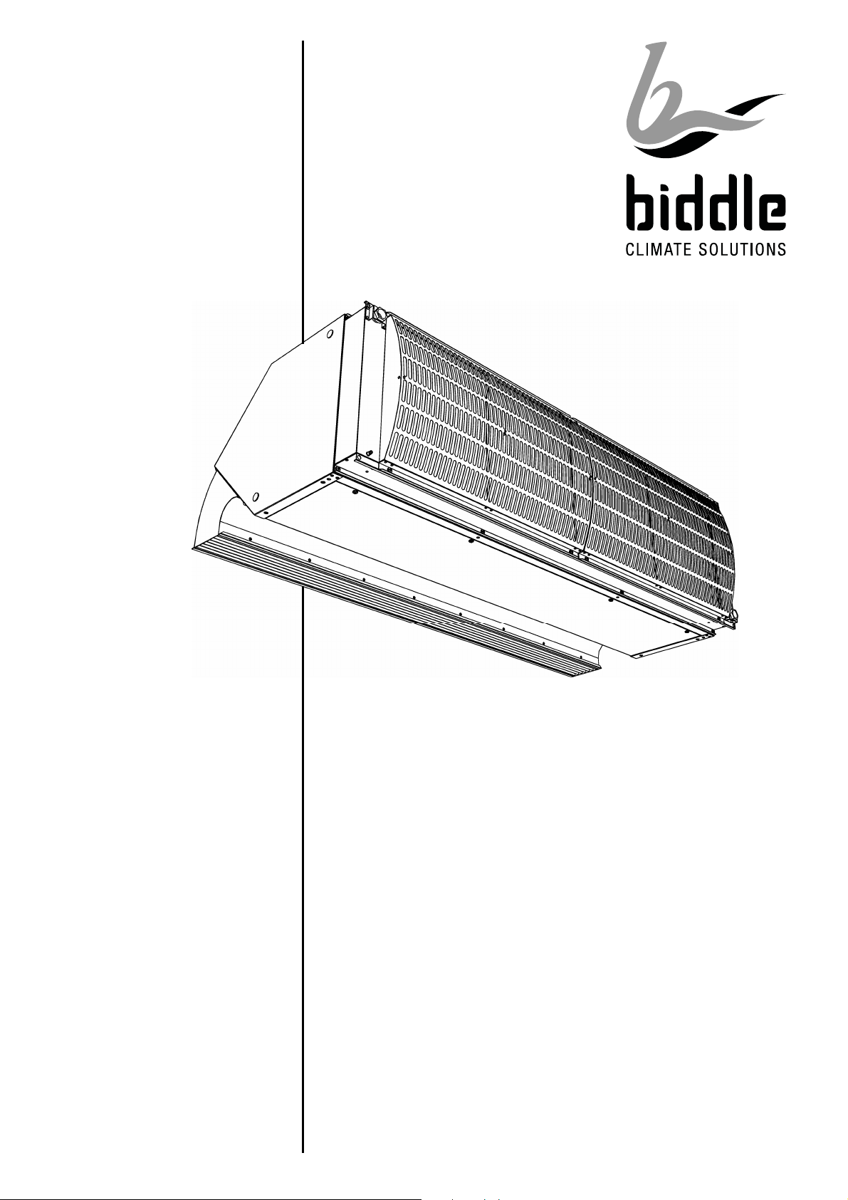
Industrial Air Curtain
Model IndAC
Version 2.1
27-10-2008
English
Page 2

B
Copyright
All the information and drawings in this manual are the property of Biddle and may not be
used (other than for the actual operation of
the device), photocopied, duplicated, translated and/or be brought to the attention of
third parties without Biddle’s prior written
permission.
The name Biddle is a registered trademark.
Trademarks
The name Biddle is a registered trademark of
Biddle bv.
Warranty (guarantee) and
liability
Please refer to Biddle's Terms of Sales and
Delivery for warranty (guarantee) and liability
conditions.
Biddle excludes liability for consequential
loss at all times and under all circumstances.
For more information
If you have any comments or questions
about specific topics relating to this product,
please do not hesitate to contact Biddle.
Addresses
United Kingdom
Biddle Air Systems Ltd.
St. Mary’s Road
Nuneaton
Warwickshire CV11 5AU
United Kingdom
Telephone: 024 7638 4233
Fax: 024 7637 3621
E-mail: [email protected]
Internet: www.biddle-air.com
Canada
Biddle Air Systems Ltd.
11 King St.
Unit # 3
Barrie, ON L4N 6B5
Liability for the contents of
this manual
However much care might have been taken
in ensuring the correctness and, where necessary, completeness of the description of
the relevant parts, Biddle disclaims all liability
for damage resulting from any inaccuracies
and/or deficiencies in this manual.
Should you detect any errors or ambiguities
in this manual then we would be pleased to
hear from you: it helps us to improve our
documentation even further.
Biddle retains the right to change the specifications stated in this manual.
telephone: 705 797 0007
fax: 705 797 0013
toll free: 866 693 4333
e-mail: [email protected]
internet: www.biddle.ca
Other countries
Biddle Export
PO Box 15
NL-9288 ZG Kootstertille
The Netherlands
Telephone: +31 512 335555
Fax: +31 512 335554
E-mail: [email protected]
Internet: www.biddle.info
2
Manual model IndAC
Page 3

Industrial Air Curtain Contents
2.5 Installing units vertically .................. 10
Contents
1 Introduction ........................4
1.1 About this manual ............................. 4
1.2 How to use this manual .................... 4
1.2.1 Marginal symbols in the manual ......... 4
1.2.2 Pictograms used on the unit and in
the manual................................................... 4
1.2.3 Related documentation....................... 4
1.3 About the unit.................................... 5
1.3.1 Applications ........................................ 5
1.3.2 Principle of operation.......................... 5
1.3.3 Type designation, unit......................... 5
1.3.4 Installation positions ........................... 6
1.3.5 Type plate ........................................... 6
1.4 Required parts .................................. 6
1.4.1 Supplied parts..................................... 6
1.4.2 Accessories ........................................ 7
1.4.3 Parts not supplied............................... 7
1.5 Safety instructions ............................ 7
1.5.1 Operation............................................ 7
1.5.2 Installation, maintenance and
service ......................................................... 7
2 Installation..........................8
2.5.1 Method of installation........................ 10
2.5.2 Positioning ........................................ 10
2.5.3 Installing the units..............................11
2.5.4 Securing ........................................... 12
2.6 Connecting units to the CH system 12
2.6.1 General............................................. 12
2.6.2 Connecting water pipes .................... 13
2.7 Connecting the fans........................ 13
2.7.1 General............................................. 13
2.7.2 Making connections within the units . 13
2.8 Connecting the electric heating ...... 14
2.8.1 General............................................. 14
2.8.2 Opening the heating section............. 15
2.8.3 Connecting the feeder cable............. 15
2.8.4 Connecting the control cable within
the units ..................................................... 15
2.9 Finishing ......................................... 16
2.10 Switching on and checking
operation............................................... 16
3 Maintenance ....................18
3.1 Safety instructions .......................... 18
3.2 Access ............................................ 18
3.2.1 Fans.................................................. 18
3.2.2 Heating element ............................... 19
3.3 Cleaning.......................................... 19
3.4 Scheduled maintenance ................. 19
2.1 Safety instructions ............................ 8
2.2 Delivery check .................................. 8
3.4.1 Monthly maintenance ....................... 19
3.4.2 Annual maintenance ......................... 20
2.3 General instructions.......................... 8
2.3.1 Order of working ................................. 8
2.3.2 Miscellaneous..................................... 8
2.4 Suspending units horizontally........... 8
2.4.1 Method of suspension......................... 8
2.4.2 Positioning .......................................... 9
2.4.3 Mounting the units .............................. 9
2.4.4 Adjusting and securing ..................... 10
4 Solving problems .............21
4.1.1 General............................................. 21
4.1.2 Unit does not discharge any air ........ 21
4.1.3 Unit discharges little air..................... 21
4.1.4 Unit does not heat, or too little.......... 21
Version 2.1, English (27-10-2008) 3
Page 4
B
d
1 Introduction
1.1 About this manual
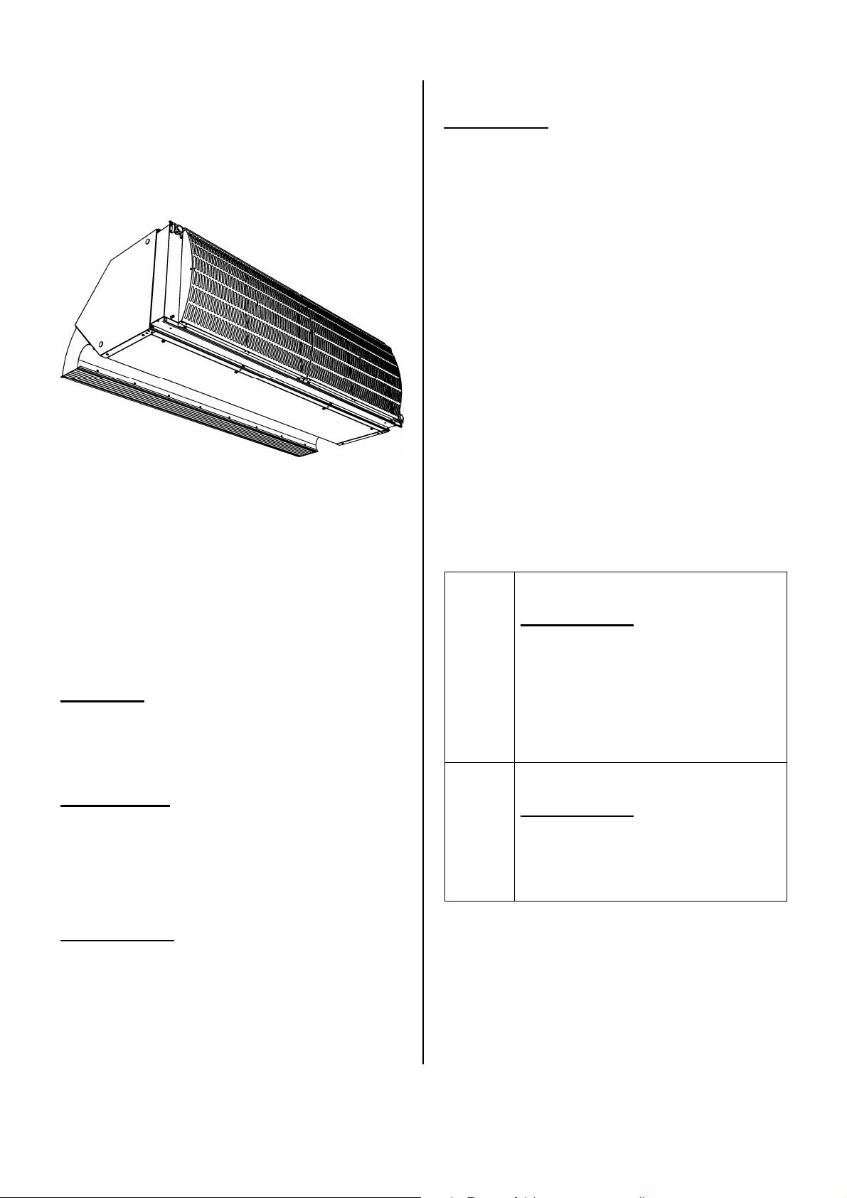
This manual describes the installation and
maintenance of the Industrial Air Curtain,
model IndAC.
Danger:
This indicates actions which are not permitted. Ignoring this warning may lead to
serious damage or accidents that may
involve physical injury.
Only for …
For units with …:
The description applies only to models that
have the feature referred to.
If no specific model is referred to, the description applies to all models.
1.2.2 Pictograms used on the unit and
in the manual
The below pictograms refer to possible risks
or dangers. These pictograms can also be
found on the unit.
1.2 How to use this manual
1.2.1 Marginal symbols in the manual
n
Note:
Draws your attention to an important part of
the text.
c
Caution:
If you do not carry out this procedure or
action correctly, you may damage the unit.
So, follow the instructions carefully.
w
Warning:
If you do not carry out this procedure or
action correctly, you may cause material
damage and/or physical injury.
So, follow the instructions carefully.
ê
ç
1.2.3 Related documentation
In addition to this manual, the following document is supplied with the unit:
- wiring diagram for installation and service purposes.
w
Warning:
You are entering an area which
contains live components.
Accessible to qualified maintenance staff only. Caution is
urged.
w
Warning:
This surface or part can be hot.
There is a risk of burns on contact.
4
Manual model IndAC
Page 5
Industrial Air Curtain 1 Introduction
1.3 About the unit
1.3.1 Applications
The air curtain model IndAC is designed to
separate the indoor and outdoor climates or
the climates in two rooms. It is installed
above or next to the door, across the full
width or length of the doorway. The IndAC
model is particularly suitable for larger doors
in industrial buildings.
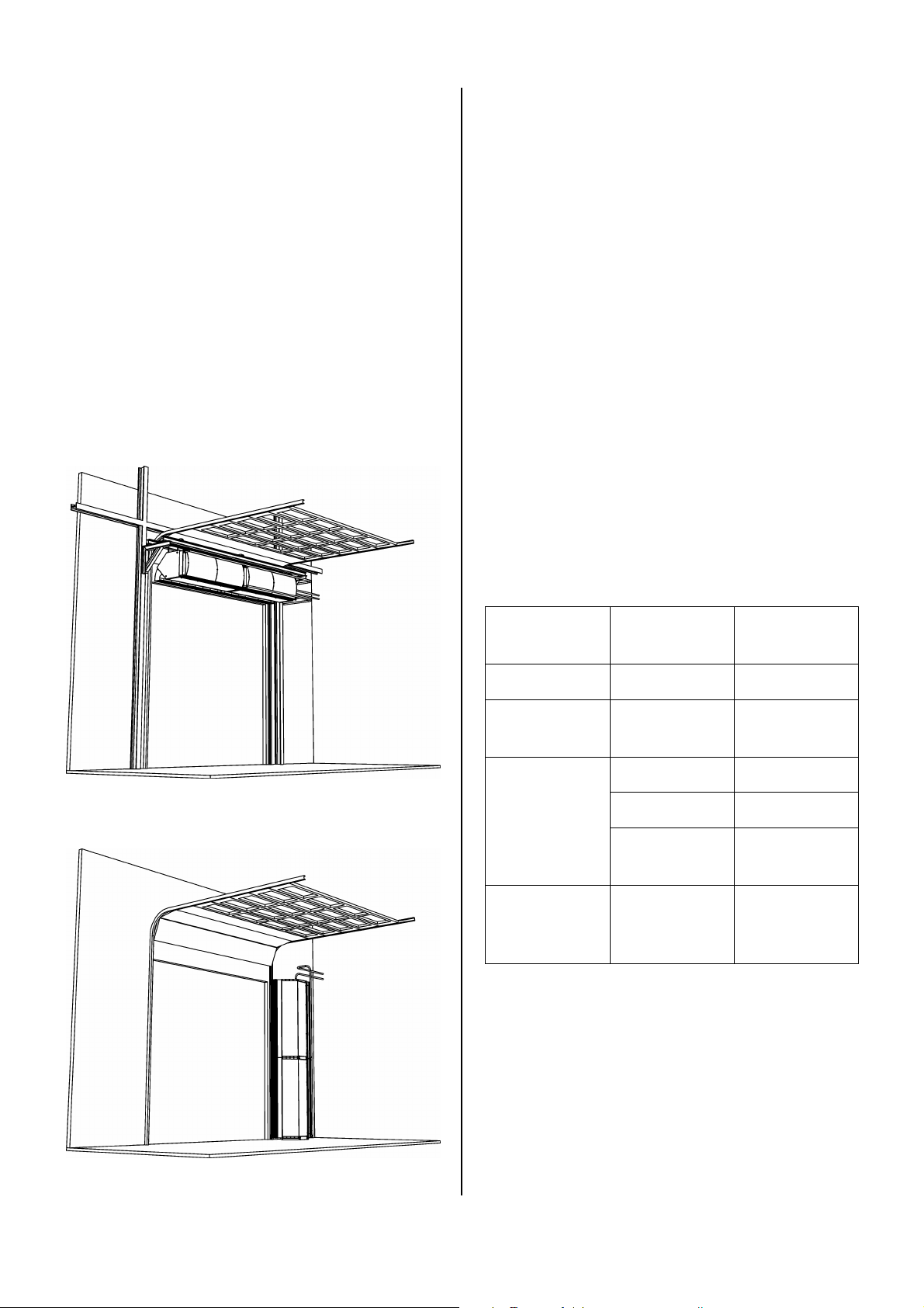
Depending on the type, the air curtain is
either hung horizontally above the doorway
or installed vertically next to the doorway (to
the left or right or on both sides).
1.3.2 Principle of operation
The air curtain draws air from the room and
blows it, either heated or not, as a directional
air stream across the doorway.
The air curtain reduces the undesired effects
of an open door by either reducing the exchange of air between two rooms or heating
the entering air, or by combining these two
features.
1.3.3 Type designation, unit
The type designations, when combined,
constitute the type code for the relevant unit,
for instance:
IndAC S-150-W1-0
IndAC M-200-E-1L
IndAC L-225-A-2R
Example of a horizontal installation
Various combinations can be made.
Explanation of type code of unit
Series
Range
Unit Size
Heating
Installation
Position
IndAC
S, M, L, XL
150, 200, 225
W1, W2, W3
E
A
0
1L, 1R
2L, 2R
Industrial Air
Curtain
air discharge
length (in cm)
hot water
electric
without heating (Ambient)
See section
1.3.4.
Example of a vertical installation
Version 2.1, English (27-10-2008) 5
Page 6
B
1.3.5 Type plate
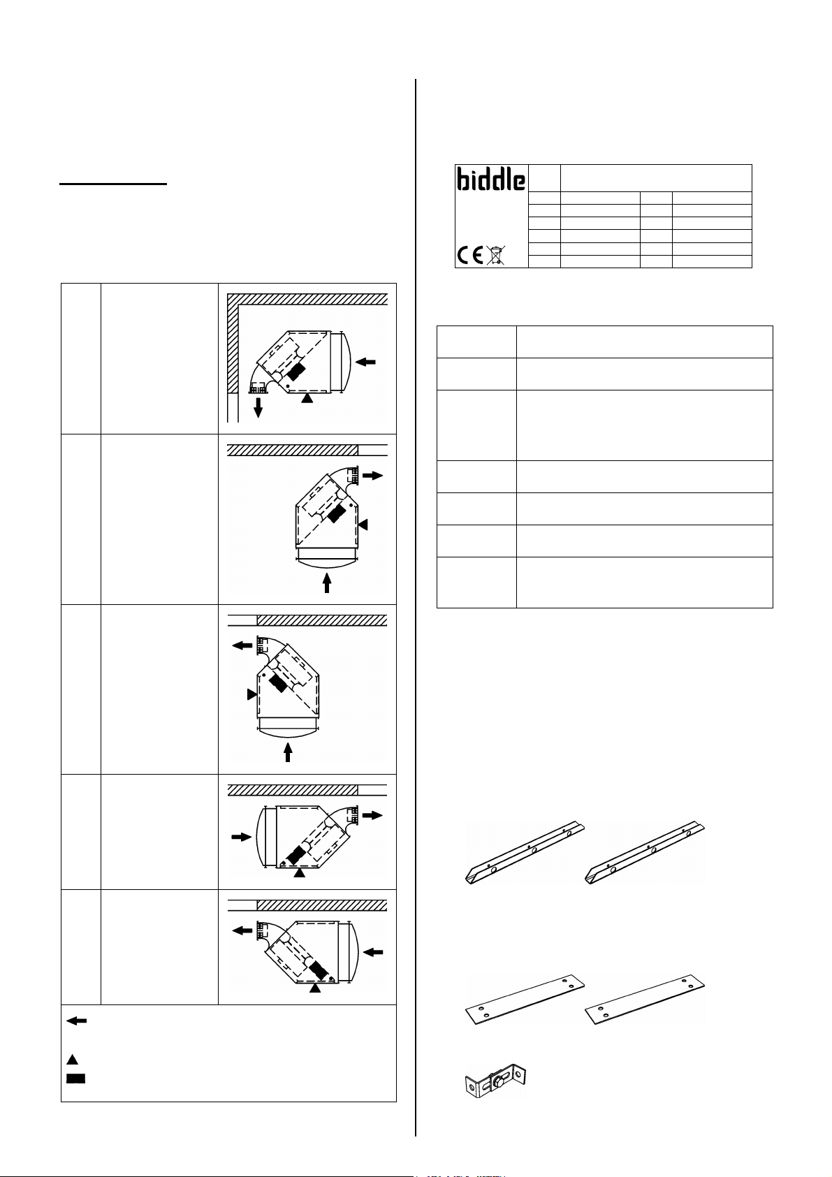
1.3.4 Installation positions
c
Caution:
The unit has been specifically designed for
the installation position indicated in the type
code. The unit cannot be used in a different
position.
horizontal,
0
above door
vertical, left of
1L
door, square to
wall
You will find the type plate on the heating
section of the unit.
Type IndAC M-200-W2
Biddle bv
Markowei 4
NL-9288 HA Kootstertille
Example of a type plate
References on the type plate
Type
M
P
max
U
I
max
Code U 400 V 3N~ 50 Hz
Nº 123456/1-1 06-36 I
M 133 kg I
Medium LPHW P
p
800 kPa P
max
max
I
max
max
heating
L1 2,1 A
L2 2,1 A
L3 2,1 A
motor
1,08 kW
-
full type code of unit
weight of unit
maximum permissible operating
pressure (for units with water heating)
supply voltage
maximum current strength
vertical, right of
1R
door, square to
wall
vertical, left of
2L
door, parallel to
wall
vertical, right of
2R
door, parallel to
wall
P
motor
P
heating
maximum input power for fans
maximum input power for heating
(with electrically heated units)
1.4 Required parts
1.4.1 Supplied parts
With each installation:
- cable to connect units to each other
With horizontal installation:
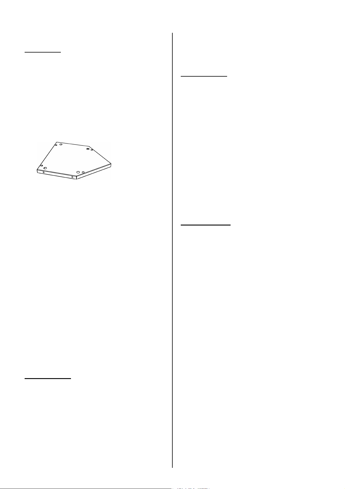
- suspension rails (2 per unit, also used for
fixing the unit to the pallet)
With vertical installation:
intake and discharge direction (not to be
blocked)
inspection side (to be accessible)
fan terminal box
6
- coupling plates (2 per unit)
- securing bracket
Manual model IndAC
Page 7
Industrial Air Curtain 1 Introduction
1.5.2 Installation, maintenance and
n
Note :
On delivery, some parts may have been
packaged within the unit (behind the inspection panel).
1.4.2 Accessories
service
w
Warning:
The unit may be opened by qualified
technical staff only.
With each installation:
- control unit (always required)
With vertical installation:
- base plate (recommended)
1.4.3 Parts not supplied
The following parts required for installation
should be purchased from other suppliers:
- threaded rods (metric M12)
- cable to connect unit and control unit
- isolating switch
ê ç
Before opening the unit:
- Switch the unit off with the control unit.
- Wait until the fans have stopped.
- Allow the unit to cool down as the heat
exchanger can be very hot.
- Switch the unit off at the mains.
- Close CH supply (if possible).
w
The fins of the heat exchanger are sharp.
Warning:
- fuse for control unit
- door contact switch (optional)
- room thermostat (optional)
1.5 Safety instructions
1.5.1 Operation
w
Warning:
Do not insert any objects into the intake
and discharge openings.
Never block the intake and discharge
openings.
ç
For units with heating: the intake side can
be hot.
Version 2.1, English (27-10-2008) 7
Page 8
B
2.3.2 Miscellaneous
2 Installation
c
Caution:
The infiltration of coarse dust, cement, etc.
2.1 Safety instructions
may damage the unit. So long as such contaminants are in the room,
w
Warning:
Installation works may be performed by
qualified technical staff only.
Do not perform any connection work
unless you are qualified to work with
400V three-phase current.
Before opening the unit, follow the safety
instructions in section 1.5.
2.2 Delivery check
- On delivery, check the unit and its pack-
aging. Report any transit damage immediately to the driver and supplier.
- Make sure that all parts have been supplied (see section 1.4). Report any defects to the supplier immediately.
- do not put the unit into operation;
- cover the intake and discharge openings.
The packaging, for example, can be used for
this.
2.4 Suspending units
horizontally
Only with installation position type 0
2.3 General instructions
2.3.1 Order of working
Biddle recommends following the order of
working described in this section for performing the installation works.
n
Note:
Make sure you perform all operations that
are required for the installation of your unit.
Check the type plate and refer to section
1.3.5 if you are not sure about the model or
type of your unit.
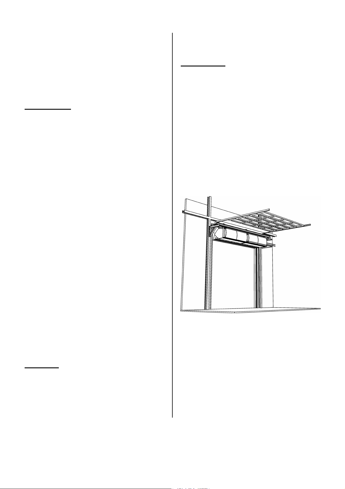
Example of a horizontal installation
2.4.1 Method of suspension
This manual assumes suspension from an
auxiliary structure, consisting of two horizontal beams positioned above the door.
8
Manual model IndAC
Page 9
Industrial Air Curtain 2 Installation
Example of an auxiliary structure
You may also fix the units directly to the
ceiling, or to another horizontal structure,
using the screw holes in the upper side of the
unit.
Make sure that the structure from which the
unit is to be suspended can hold the weight
of the unit.
2.4.2 Positioning
- Position the bottom face of the unit at the
same height as the doorway.
- Position the discharge side of the unit as
closely as possible to the doorway to ensure optimum operation.
- Center the row of units in relation to the
doorway.
- Units of different widths can be positioned in random order.
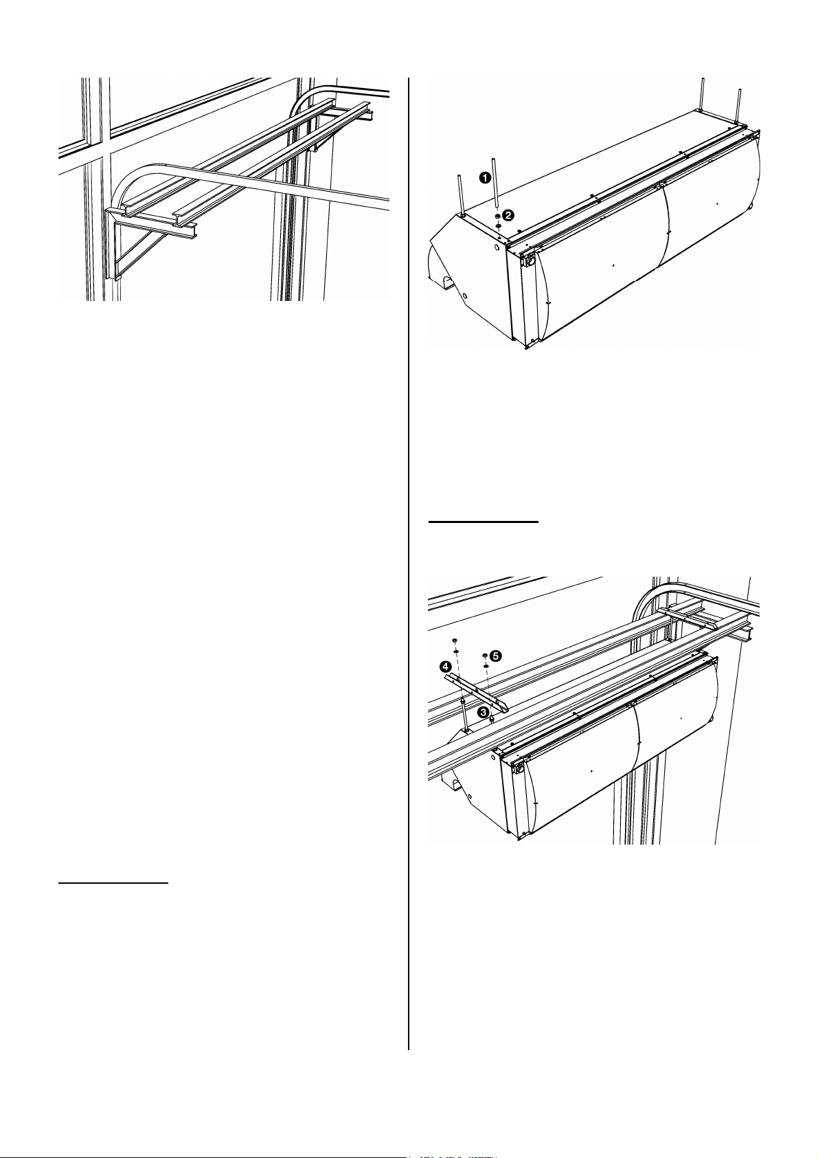
2 Insert threaded rods 1 (M12) into the
four screw holes in the upper side of the
unit.
3 Provide all threaded rods with locknuts
2, and tighten these.
w
Warning:
The threaded rods must be secured, otherwise the unit may come down.
- Make sure that the inspection and intake
sides of the units remain accessible for
maintenance.
w
Warning:
Ensure that all units can freely take in and
blow out air across the entire width.
2.4.3 Mounting the units
Perform the following for each unit:
1 Lay the unit down in horizontal position.
Version 2.1, English (27-10-2008) 9
4 Provide all threaded rods with lock-
nuts 3.
5 Bring the unit into position using lifting
equipment.
6 Put the suspension rails 4 upon the
auxiliary structure, and fasten them with
nuts 5 to the threaded rods of the unit.
7 Allow the unit to hang freely.
Page 10
B
2.4.4 Adjusting and securing
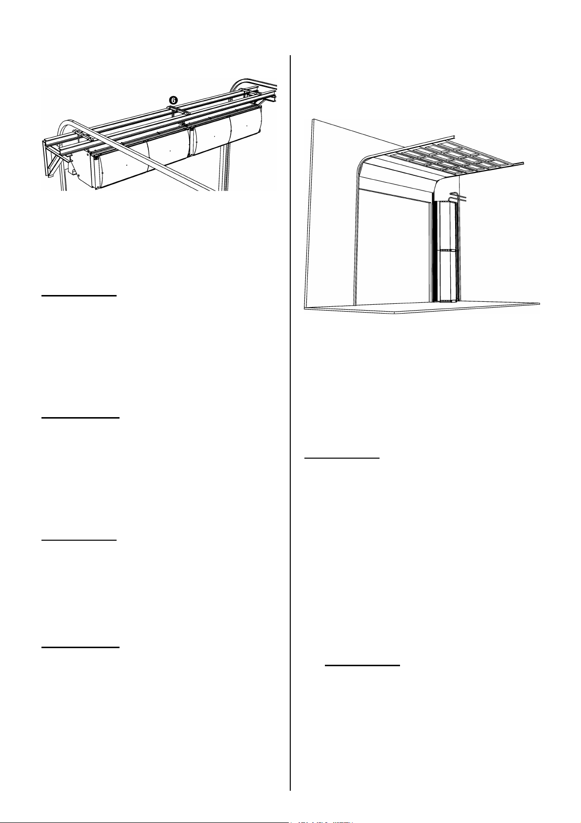
1 Position the units against one another, in
one line, by placing the suspension rails
6 against one another. You may want to
fix the suspension rails to one another.
c
Caution:
Allow the units to hang independently from
each other. Do not fix them directly to one
another.
2.5 Installing units vertically
Only with installation position types 1
and 2
Example of a vertical installation
2 Fasten the suspension rails to the auxil-
iary structure.
w
Warning:
Make sure that the suspension rails can
never come loose from the auxiliary
structure.
3 Adjust the units to the same height, and
level them by tightening the nuts 5.
c
Caution:
Ensure that the units are level in both directions; otherwise the fans may run out of true.
4 Secure the suspension to the threaded
rods by tightening the locknuts 3.
w
Warning:
The threaded rods must be secured, otherwise the unit may come down.
2.5.1 Method of installation
This manual assumes that the unit will be
placed on a base plate (accessory). The
units are stacked on one another.
c
Caution:
If no base plate is used, provide for a horizontal and completely even surface, otherwise the fans may run out of true.
Whilst the units could be standing freely, it is
always necessary to secure them to the wall.
2.5.2 Positioning
- Depending on the type, position the units
to the left or right side of the door. Refer
to section 1.3.4.
c
Caution:
Do not install the unit in any position
other than that for which it is designed.
10
- Position the discharge side of the unit at
the same width as the doorway.
- Position the discharge side of the unit as
closely as possible to the doorway to ensure optimum operation.
Manual model IndAC
Page 11
Industrial Air Curtain 2 Installation
- Units of different dimensions can be
stacked in random order.
- Make sure that the intake and inspection
sides of the units remain accessible for
maintenance purposes.
w
Warning:
Ensure that all units can freely take in and
blow out air across the entire height.
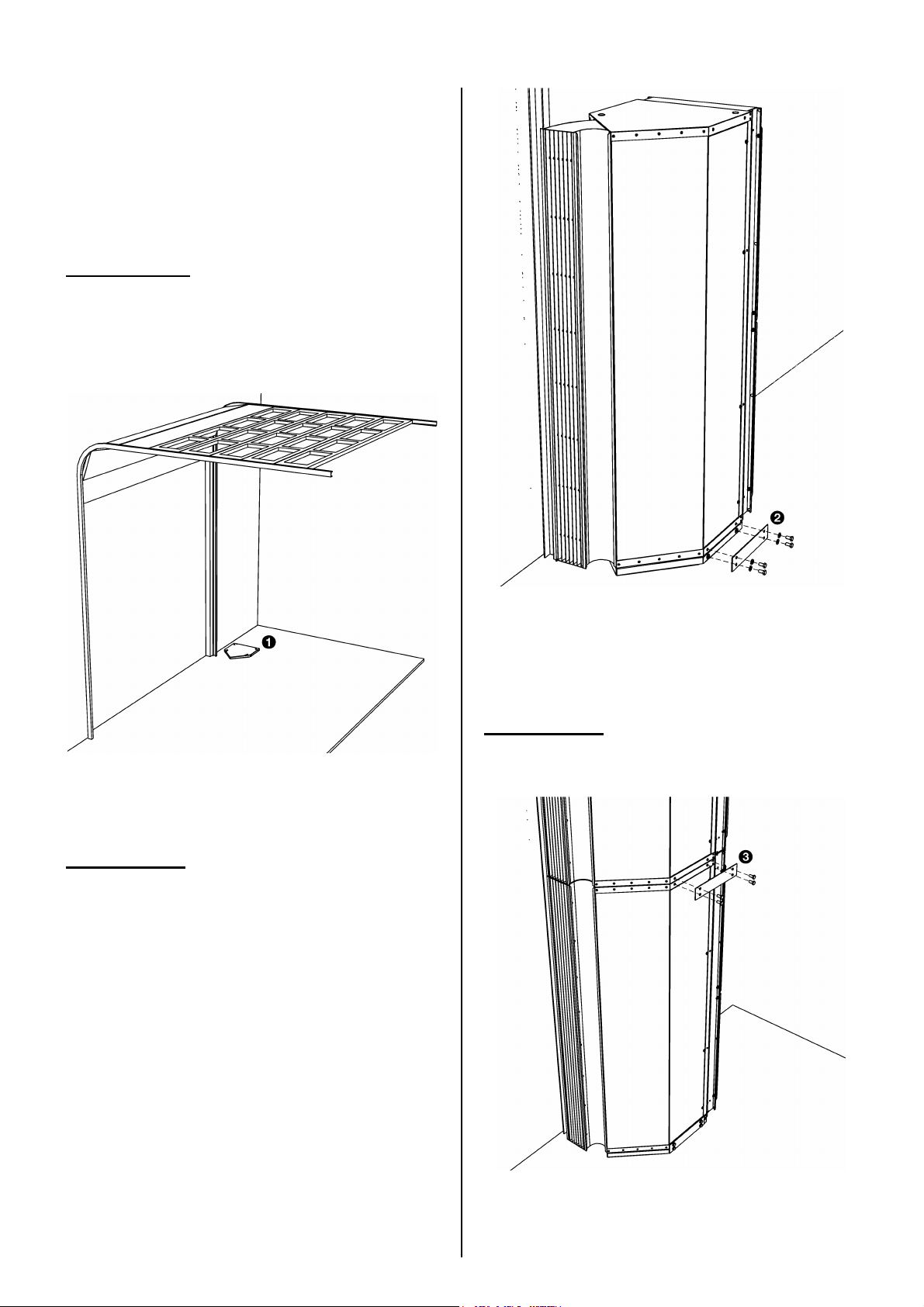
2.5.3 Installing the units
1 Position and fix the base plate 1 to the
floor.
c
Caution:
Ensure that the base plate is level.
2 Position the first unit on the base plate.
3 Fasten the unit to the base plate using
coupling plates 2.
c
Caution:
Screw the coupling plates to both sides of
the unit.
4 Position the second unit on top of the
first one, and fasten them to one another
using coupling plates 3.
Version 2.1, English (27-10-2008) 11
Page 12
B
c
Caution:
Screw the coupling plates to both sides of
the unit.
5 Position the third unit, if any, in the same
way.
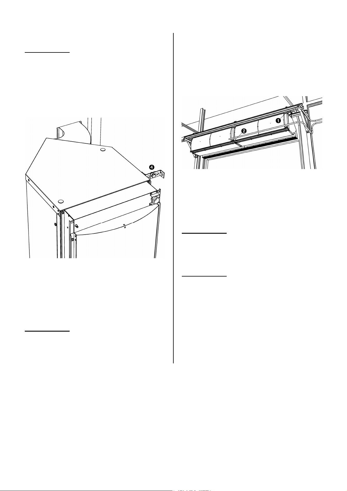
2.5.4 Securing
2.6 Connecting units to the
CH system
Only for units with water heating (type W)
2.6.1 General
The connections for the supply and return
pipes are indicated on the units using arrows.
Valves for venting 1 and draining 2 the heat
exchanger are located on the air intake side.
1 Fasten a securing bracket 4 to the top-
most unit using one of the screw holes in
the unit.
2 Fasten the securing bracket to a wall or
other permanent structure.
c
Caution:
If you place more than 3 units on top of
each other: apply a securing bracket to each
2nd or 3rd unit.
c
Caution:
Biddle recommends the inclusion of a valve
in each pipe.
c
Caution:
The fans are not resistant to high temperatures. Where necessary, take measures to
limit the discharge air temperature.
12
Manual model IndAC
Page 13
Industrial Air Curtain 2 Installation
Critical discharge air temperatures and water
temperature ranges (with 400V/50Hz only)
unit type maximum
allowed discharge air
temperature
S-W1
M-W1
S-W2
M-W2
S-W3
M-W3
L-W1
XL-W1
L-W3
XL-W3
65 °C above
65 °C above
65 °C above
65 °C above
65 °C above
water temperature
ranges where
exceedance
may occur
120/100 °C
90/70 °C or
82/71 °C
80/60 °C
130/110 °C
90/70 °C
- The mains power supply to the control
unit must be separately fused.
- In emergency and maintenance situations, it must be possible to switch off the
entire installation using an isolating
switch.
- All connections must be made according
to the applicable local laws, regulations
and standards.
w
Warning:
The units and must be earthed
(grounded).
2.7.2 Making connections within the
units
2.6.2 Connecting water pipes
1 Lay and connect the water pipes to the
units.
2 Fill the CH system.
3 Vent the heat exchangers.
4 Check the connections for leaks.
2.7 Connecting the fans
2.7.1 General
The fans in the units are powered centrally
and controlled from the control unit. The
control unit is connected to the mains power
supply.
c
Caution:
- The power supply to the fans may be
wired through between 3 units at most
(with type XL: 2 units at most).
Cabling with horizontal installation position type 0
(equal to vertical installation position type 1)
Consult Biddle if you are going to connect more than 3 units (XL: 2 units) to
one control unit.
Version 2.1, English (27-10-2008) 13
Page 14
B
- Apply a cable gland in the feed-
through 5 for pull relief purposes.
4 Connect the feeder cable to the terminal
blocks in the terminal boxes 2 according
to the wiring diagram.
c
Caution:
Do not yet switch the mains supply on.
2.8 Connecting the electric
heating
Only for units with electric heating
(type E)
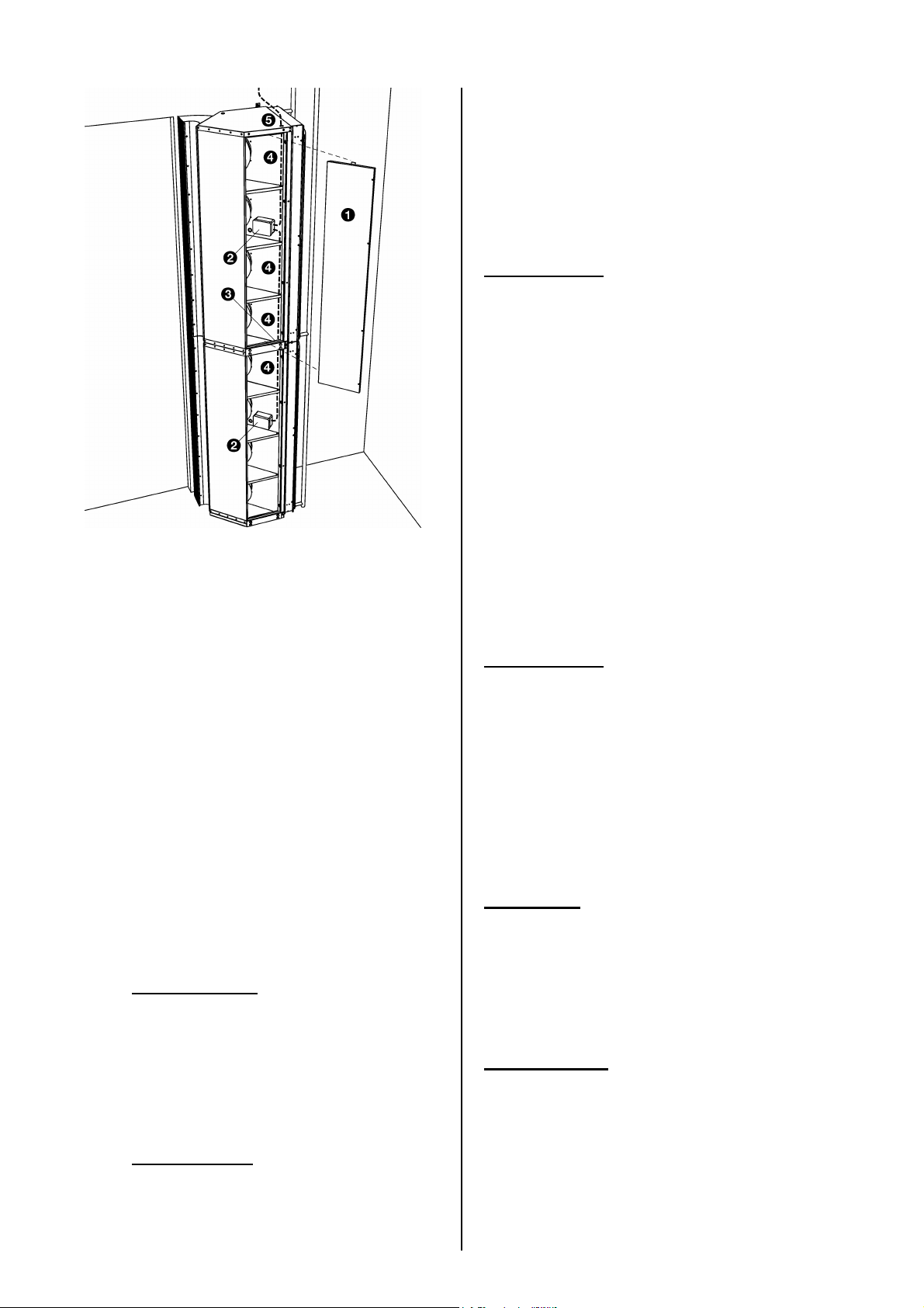
Cabling with vertical installation position type 2
1 Remove the inspection panel 1 from the
free side of the unit.
2 Remove the cover from terminal box 2.
3 Lay the feeder cable between the control
unit and the terminal box in one unit of
your choice as well as between the terminal boxes in the units.
- Lead the cable through the walls of
the units, via the holes 3 and 5.
You may lead the cable inward
through either end of the row of
units.
- Fasten the cable to the edge 4 in-
side the unit using the cable clips.
w
Warning:
Do not allow the cable to lie or
hang loosely.
- Make the grommets in the terminal
boxes to measure.
2.8.1 General
The electric heating of each unit is separately
connected to the mains power supply. The
heating is controlled using the control unit.
c
Caution:
- In emergency and maintenance situa-
tions, it must be possible to switch off the
entire installation using an isolating
switch.
- All connections must be made according
to the applicable local laws, regulations
and standards.
n
Note :
Each unit has an isolating switch to facilitate
maintenance. This switch switches off only
the electric heating of the relevant unit and
does not affect the fans or the other units.
w
Warning:
The units must be earthed (grounded).
14
c
Caution:
Ensure the grommets have such
tight fit around the cable that they
remain watertight.
Manual model IndAC
Page 15
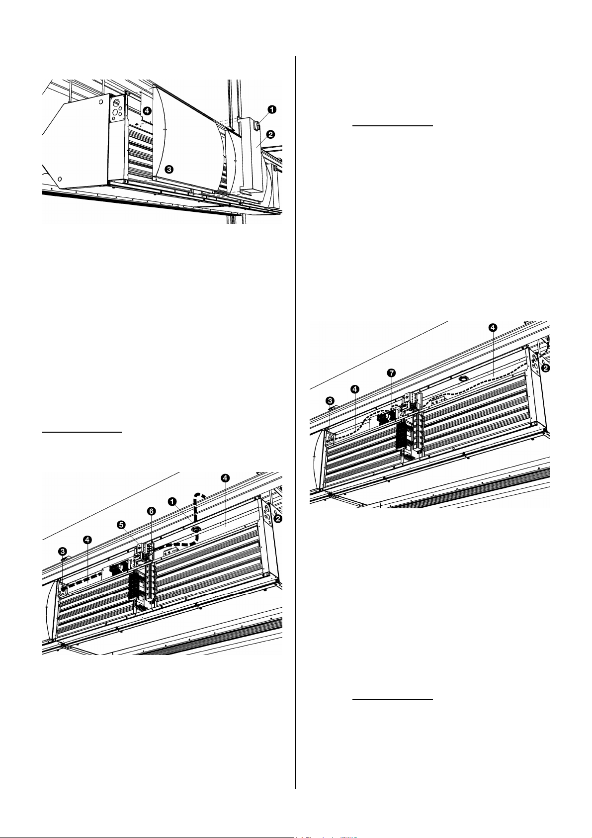
Industrial Air Curtain 2 Installation
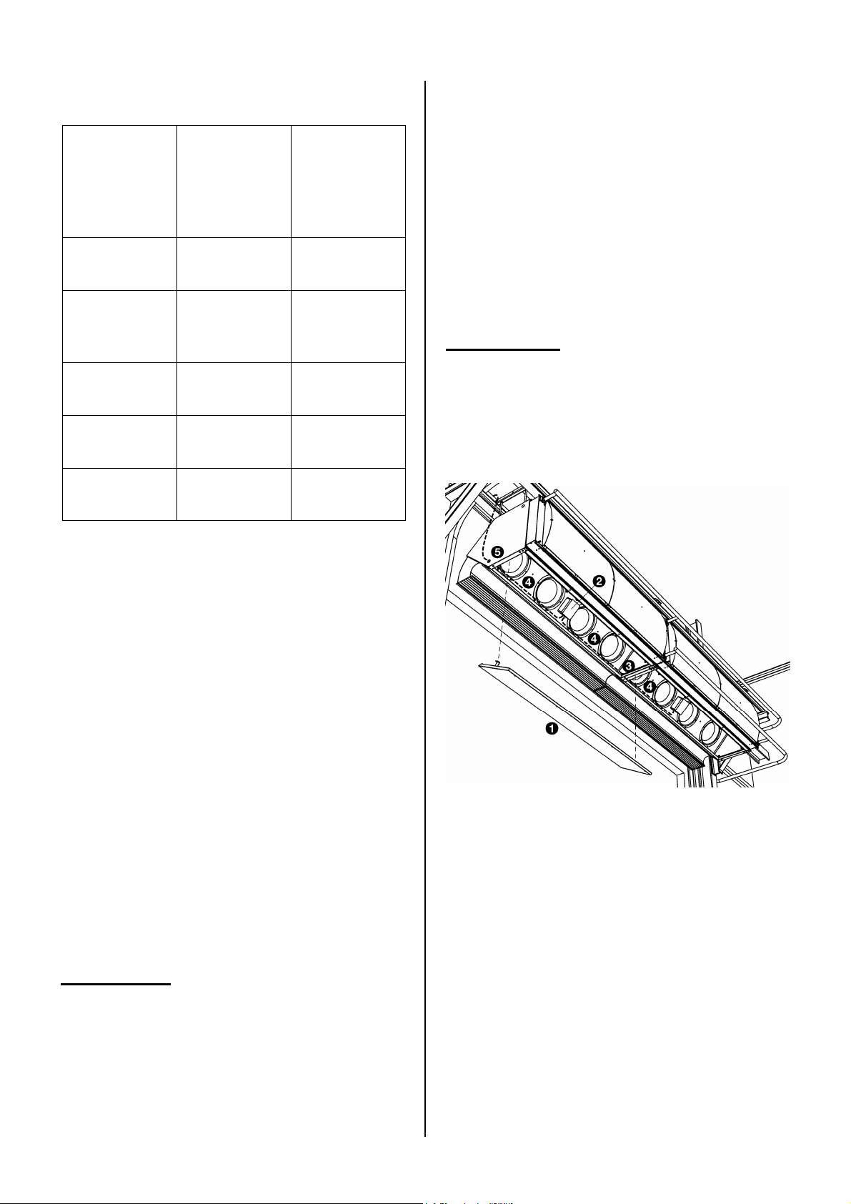
2.8.2 Opening the heating section
Perform the following for each unit:
1 Set the isolating switch 1 on the unit to
the zero position.
2 Remove the cover 2.
3 Remove the inlet grille 3.
4 Remove the cover from the cable com-
partment 4.
- Lay the cable in the cable compart-
ment 4.
w
Warning:
Do not allow the cable to lie or
hang loosely.
- Apply a cable gland in the feed-
through for pull relief purposes.
2 Connect the feeder cable to the isolating
switch 5 (blue) according to the wiring
diagram. Connect the earth cable to the
terminal block 6 (green and yellow).
2.8.4 Connecting the control cable
within the units
2.8.3 Connecting the feeder cable
w
Warning:
Make sure that the mains power supply is
switched off.
Perform the following for each unit:
1 Lay the control cable between the control
unit and one unit of your choice as well
as between the different units.
- Lead the cable either through hole 2
or 3. You may lead the cable inward
through either end of the row of
units.
- Lay the cable in the cable compart-
ment 4.
1 Lay the feeder cable to the unit:
- Lead the cable through either hole 1
or 2 or 3. You may lead the cable
through an adjacent unit.
- Where necessary, interchange the
cable entry plate at hole 2 or 3.
Version 2.1, English (27-10-2008) 15
w
Warning:
Do not allow the cable to lie or
hang loosely.
- Apply a cable gland in the feed-
through for pull relief purposes.
Page 16
B
2 In each unit, connect the control cable to
the terminal block 7 according to the
wiring diagram.
2.9 Finishing
For units with electric heating:
1 Place cover 4 back on the cable com-
partment.
2 Place the inlet grilles 3 back.
3 Place the cover 2 back.
2.10 Switching on and
checking operation
For all units:
1 Check the following connections:
- power supply;
- cabling between control unit and
units, and between the different
units;
- external control components (if any).
2 Switch the mains supply on.
3 Switch the air curtain on using the control
unit, and check if the air curtain blows
out air.
c
Caution:
If the fans run out of true, the unit may
not be standing or hanging completely
level. Correct this where necessary.
For all units:
4 Place the covers back on the terminal
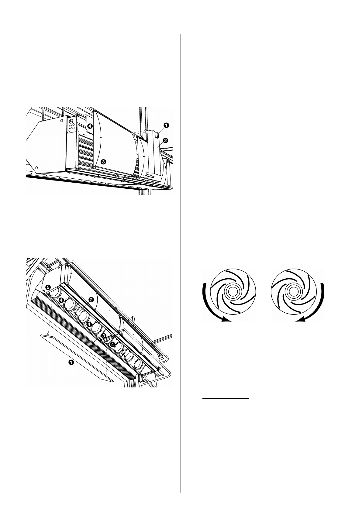
boxes 2 in order to protect the connections from dirt and cleaning.
5 Place the inspection panels 1 back.
4 Check the direction of rotation of the
fans.
wrong: the blades
go forward
If necessary, correct the direction of rotation by interchanging the connections of
two phases from the mains supply.
c
Caution:
The fans are not resistant to prolonged
rotation in the wrong direction.
For water-heated units:
correct: the blades
go backward
16
5 Check if the heat exchanger is con-
nected correctly.
6 Make sure the CH system is turned on.
7 Feel whether the discharged air gets
warm.
Manual model IndAC
Page 17

Industrial Air Curtain 2 Installation
8 Vent the heat exchanger, if necessary.
For units with electric heating:
9 Set the isolating switches on all units to
position 1.
10 Switch the air curtain on using the control
unit.
11 Feel if the discharged air gets warm.
Version 2.1, English (27-10-2008) 17
Page 18
B
3 Maintenance
3.1 Safety instructions
w
Warning:
Maintenance works may be performed by
qualified technical staff only.
Before opening the unit, follow the safety
instructions in section 1.5.
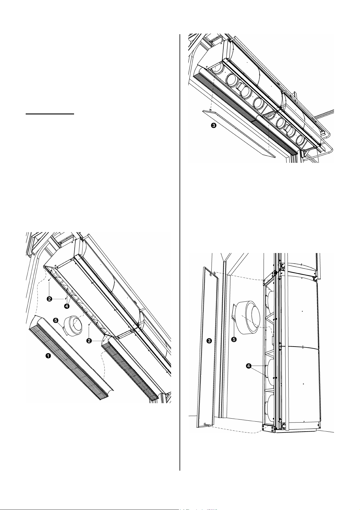
1 Remove the discharge section 1: loosen
3.2 Access
bolts 2 and unhook the discharge section.
3.2.1 Fans
With horizontal installation position type
0, and vertical installation position type 1:
2 To access the terminal box of the fans:
remove inspection panel 3.
3 To take out the fans: loosen bolts 4 and
take out the fan along with bracket 5.
With vertical installation position type 2:
18
1 Remove inspection panel 3.
2 To take out the fans: loosen bolts 4 and
take out the fan along with bracket 5.
Manual model IndAC
Page 19
Industrial Air Curtain 3 Maintenance
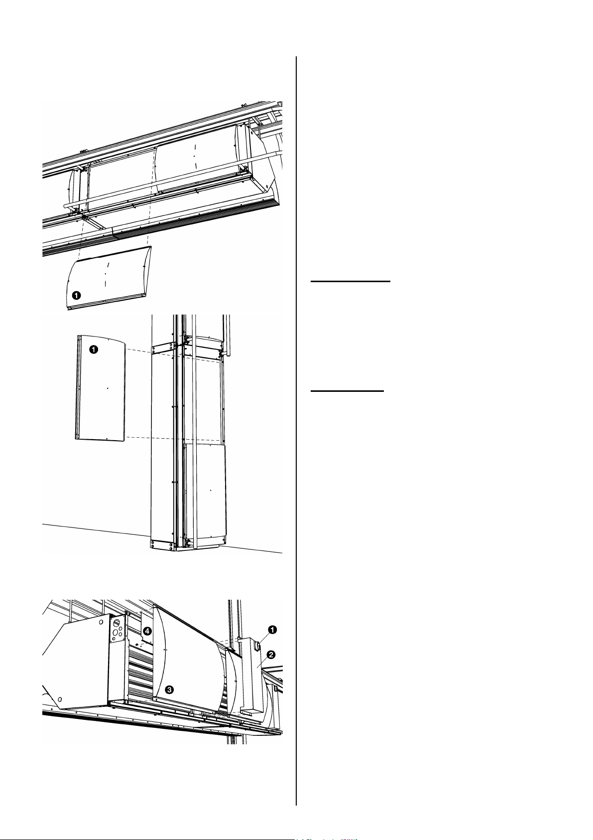
3.2.2 Heating element
For water-heated units:
3 Remove the inlet grille 3.
4 Remove the cover from the cable com-
partment 4.
3.3 Cleaning
You can clean the unit's interior and exterior
with water and a domestic cleaning agent.
Do not use any solvents.
The fans can be cleaned with water as well.
The unit has holes for the discharge of water.
w
Warning:
Do not spray water on the fans and terminal boxes.
Carefully remove dust from the heating element with a vacuum cleaner.
1 Remove inlet grille 1.
For units with electric heating:
d
Danger:
Do not clean electrically-heated units with
water.
3.4 Scheduled maintenance
3.4.1 Monthly maintenance
- Check the heating elements and the fans
for dust and other contaminants. Clean if
necessary.
- Check if all fans are working.
- Check if the air curtain is working at all
control unit settings.
- Check the discharge section for contaminations and/or blockages; clean if
necessary.
For units with water heating:
- Check for water leaks. If there is a leak,
disconnect the unit from the mains, and
1 Set the isolating switch 1 on the unit to
the zero position.
2 Remove the cover 2.
Version 2.1, English (27-10-2008) 19
repair the leak.
- Check if the water circuit contains any
entrapped air. Bleed if necessary.
Page 20

B
3.4.2 Annual maintenance
- Perform all monthly checks.
- Check the cabling between the terminal
boxes in the units and the control unit.
- Check the casing, the hanging or fixing
construction, and the securing of each
unit.
- Check if the fans are mounted correctly
and are not running out of true. If necessary, fasten them again.
For units with electric heating:
- Check the wiring between the control unit
and the heating section.
- Check the feeder cables and the connections in the heating section.
- Check the relays in the heating section.
20
Manual model IndAC
Page 21
Industrial Air Curtain 4 Solving problems
For electrically heated units:
4 Solving
problems
4.1.1 General
If the air curtain does not work, or not properly, perform the checks mentioned below.
If that does not help, there may be a defect.
In that case, alert the installer.
4.1.2 Unit does not discharge any air
1 Check whether the air curtain has been
switched on by the control unit: see the
control unit documentation.
2 Check if the unit is not disabled by an
external control component (door switch
or room thermostat).
3 Check if mains power is supplied.
4 Check whether the isolating switch on all
units is set to position 1.
5 Check if mains power is supplied to each
unit.
6 Reset the high-limit thermostat: see the
control unit documentation
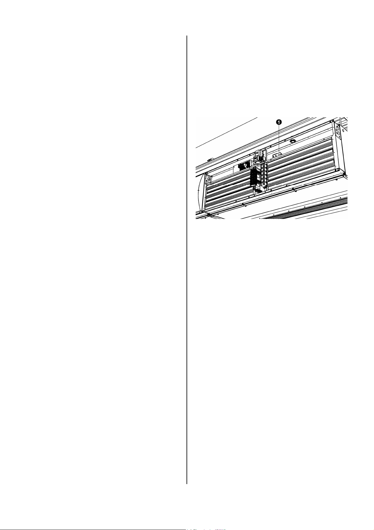
7 Check the control knob 1 in the unit: it
must always be set to 60° C.
4 Reset the thermal protector of the fans
to: see the control unit documentation.
4.1.3 Unit discharges little air
1 Remove obstacles in front of intake and
discharge openings.
2 Check the heat exchanger for contami-
nation. Clean it if necessary.
3 Check the direction of rotation of the
fans: see section 2.10.
4.1.4 Unit does not heat, or too little
1 When facing draught: select a higher fan
speed using the operation switch.
2 Does the unit blow out enough air? If not,
perform the checks in sections 4.1.2 and
4.1.3.
For water-heated units:
3 Check the operation of the CH system.
Version 2.1, English (27-10-2008) 21
Page 22

B Blank
22
Manual model IndAC
Page 23

Industrial Air Curtain Blank
Version 2.1, English (27-10-2008) 23
Page 24

Declaration of Conformity
Manufacturer: Biddle BV
Address: Markowei 4
9288 HA Kootstertille
THE NETHERLANDS
We declare that the following product.
Product description: Industrial air curtain
Brand: Biddle
Model: IndAC
Type: IndAC S-150-W, S-200-W, M-150-W, M-200-W
IndAC L-150-W, L-225-W, XL-150-W, XL-225-W
IndAC S-150-E, S-200-E, M-150-E, M-200-E
IndAC S-150-A, S-200-A, M-150-A, M-200-A
IndAC L-150-A, L-225-A, XL-150-A, XL-225-A
In accordance with the following Directives:
73/23/EEC the Low Voltage Directive
89/336/EEC the Electromagnetic Compatibility Directive
Has been designed and manufactured to the following specifications:
EN 50081-2:1993 EMC – Generic emission standard
part 2. Industrial environments.
EN 50082-2:1994 EMC – Generic immunity standard
part 2. Industrial environments.
I hereby declare that the equipment named above has been designed to comply with the relevant
sections of the above referenced specifications. The unit complies with all essentials requirements of
the directives.
Signed by : P. Stoelwinder, Managing Director, 2007
CE declaration IndAC standard.doc
 Loading...