

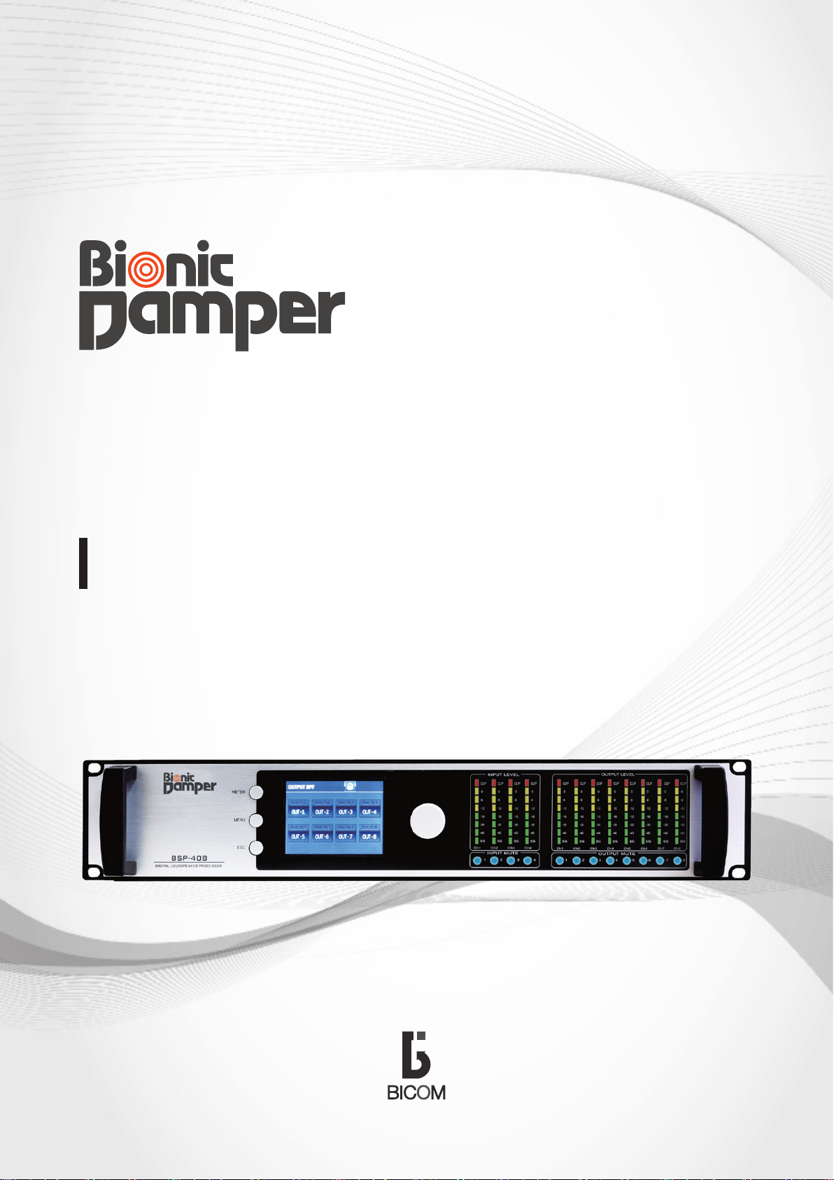
OPERATION MANUAL
DIGITAL LOUDSPEAKER PROCESSOR
BSP - 408
Before use
Make sure to read the instructions carefully before use and use the product in the correct manner to exert the
functions of this product sufficiently for long.
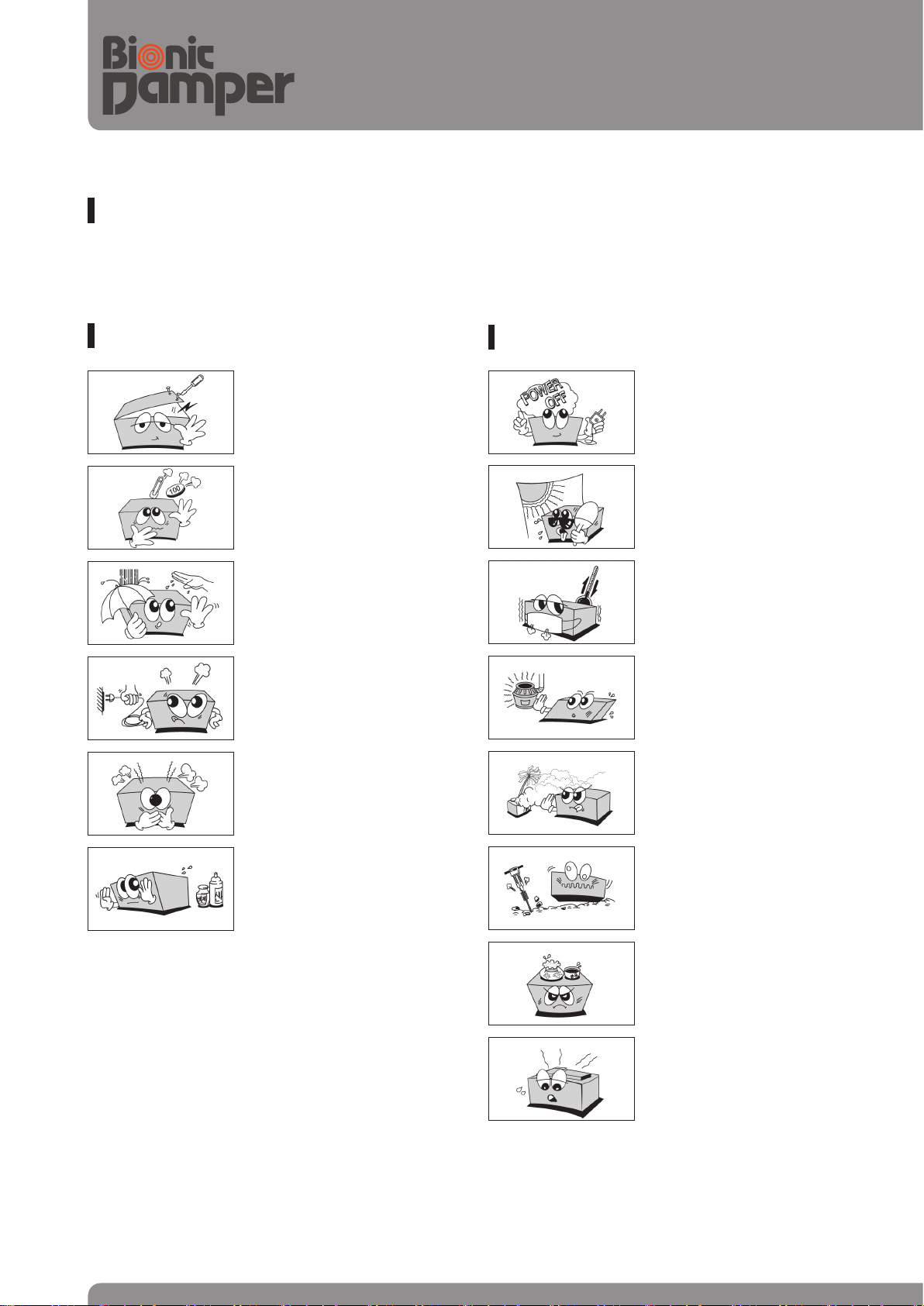
Cautions for handling
Do not open the cap of the
product. If you touch inside the
product it may result in electric
shock.
If hair pin, coins or other foreign substances enter into the
product, it may result in elec
tric shock or fire.
Do not touch the product with
wet hands. It may result in
electric shock.
Do not disconnect the power plug
while grasping the cord, otherwise
the cord may be damaged and result
in short circuit or disconnection. Make
sure to hold the plug to disconnect.
If there is a strange smell or a strange
sound or smoke is coming from the
product, disconnect the power plug
immediately and contact a nearby
Service Center.
Cautions for installation
Do not connect power plug into the
power outlet before access completion between each of device of this
product. Otherwise it may result in
breakdown.
Do not install where exposed
to direct sunlight.
-
Do not install where temperature varies by large extent.
Do not install around heater.
Do not install where of high
humidity or dust.
Do not use chemicals such as
gasoline, benzene, or thinner
but use dry and clean fabric.
02
This product is sensitive at vi
bration and do not install at a
location exposed to vibration.
Do not place a water container
or vases on the product.
Do not block ventilating open
ing. Otherwise, it may result in
product malfunction.
-
-
DIGITAL LOUDSPEAKER PROCESSOR
BSP - 408
Safety instructions
Read carefully ‘safety instructions’ and ‘operation manual’ before use and use in the correct manner.
After reading, keep this at a location to refer at any time.
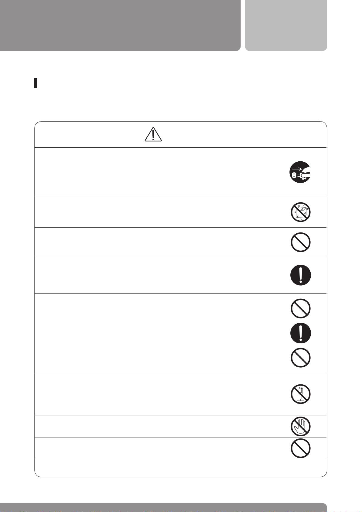
Warning
■ If there is a strange sound or smoke is coming from the product, turn off the power
switch immediately and disconnect the power plug. If you continue to use at this
abnormal condition, this may result in electric shock or fire. Make sure that smoke
is not coming from and request repairmen to the store of purchase or this company
service center. Do not repair by consumer himself.
■ Do not put into water or soak this product, or it may result in fire or electric shock.
Be cautious for usage when it rains or falls snow or when using near water or sea.
■ Make sure that metal or flammable foreign substance into the product from ventilating
hole. Be cautious especially at home having babies.
■ Keep distance of 10 cm from the wall when installing this product. For heat dissipa-
tion, keep apart from other devices. When putting into rack read operation manual
of each device carefully and give room accordingly. Internal heat may result in fire.
■ Do not place any heavy item or the product over the power cord or the damage of
the cord may result in fire or electric shock.
When covering the cord, do not place any heavy item on that.
■ In case the power cord has damage, ask the store of purchase or this company
service center for exchange. If you use as it is, it may result in fire or electric shock.
When covering the cord, do not place any heavy item on that.
■ Do not damage, process, pull, heat or punch the power cord. Any damage of the
cord may result in fire or electric shock.
■ Do not dissemble or remodel this product or it may result in fire or electric shock.
■ Do not open the inner cover, cabinet or cover or it may result in electric shock.
Internal inspection or repair should be asked to the store of purchase or this company service center.
■ Do not connect the power plug with the access wire accessed to the device (anten-
na, phone or other grounding wire) or it may result in electric shock.
■ Do not place next to cooking table, humidifier, or where of grease or soup bowl. It
may result in fire or electric shock
■ Minimize the sound volume before charging power
03
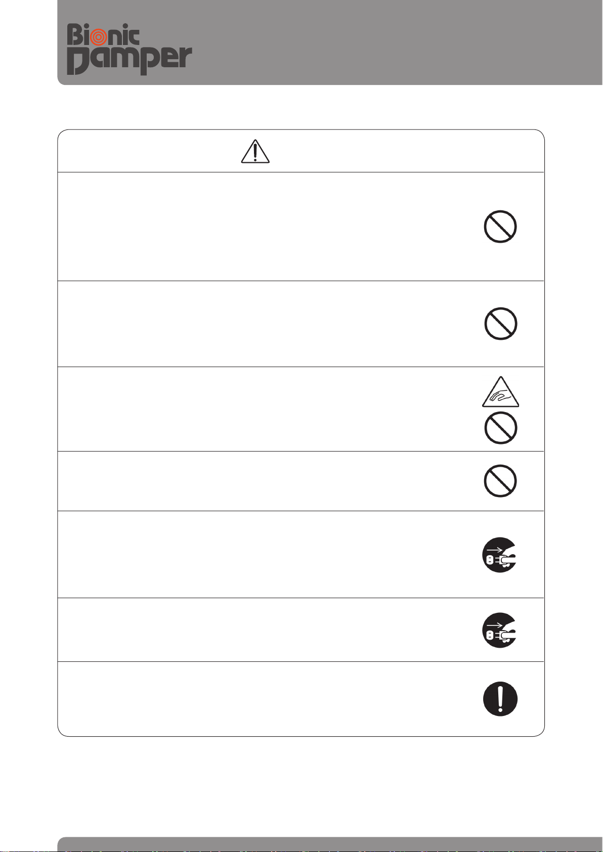
Warning
■ Do not block the ventilating hole of the product. Internal heat may result in fire.
Avoid the usage as below.
- Do not turn over or lay on its side
- Do not push into this product nor use the product in a box or other narrow place of
bad ventilation than the rack.
- Do not use on a carpet or blanket.
■ Do not hang up to the product.
Especially, be cautious that children not to fall down or get injured from breakdown.
■ Do not place any heavy or large item, or it may lose balance to fall down. It may result
in injury
■ Ensure children not to put their hands into (ventilating) opening or it may cause injury.
■ Ensure children not to play with packaging box or materials, or it may cause injury or
suffocation.
■ Do not place the power cord near heating machine. It may cause the cord to melt down
or bring about fire or electric shock.
■ Turn off the power and disconnect the power plug before move. Any problem of cord may
result in fire or electric shock.
■ Repair should be done after disconnect the power plug for safety, or it may result in
electric shock.
■ Ensure to disconnect the power plug from the outlet for safety when the product is
not used for a long time, or it may result in fire.
■ When accessing television, audio, video machine, game device or speaker, read the
operation manual of each device carefully and access accordingly after turning off
the power. Use the designated cord for access. If you use other than designated cord
or extension cord, it may overheat and result in fire.
04

DIGITAL LOUDSPEAKER PROCESSOR
Product property
■
Product Overview
DSP-based Loudspeaker Management Processor
BSP - 408
BSP series is digital loudspeaker processor of professional sound market and designed based on 40bit Float
ing Point DSP chip and high-quality converter of 96KHz and 24bit. BSP series provides 31 band graphic
equalizer, 9 band parametric equalizer, X-over (crossover), limiter and other different functions for loudspeaker management. Especially for X-Over function, it offers differentially Advanced FIR of excellent fabric property
which satisfies linear phase, as well as the conventional IIR digital filter to support excellent sound which
minimizes mutual interference between speaker units. Besides, touch-based LCD panel maximizes the convenience of user and intuitive GUI-based main control PC program supports users to set up the device as their
will via network.
■
Main Features
1) DSP-based powerful sound processing function
- support 4 channel analog and digital (AES/EBU) input and 8 channel analog and digital (AES/EBU) output
- 96 KHz Sampling Rate and high-function 24-bit A/D, D/A converter
- 31 Band graphic equalizer (both for input and output channel)
- 9 Band parametric equalizer (support Bell, Low Shelf, High Shelf)
- Various IIR filters (Bessel, Butter-Worth, Linkwitz-Riley)
- Provide linear phase FIR filter
- Phase set-up function
- Wide delay control range up to 1300msec (both for input and output channel)
- Provide limiter function (automatic control of the output signal level below the threshold level which the user
set up)
-
2) Convenience for use
- Save and load function up to 50 Preset set-ups and support one-click application of frequently used set-up
value
- 3.5 inch LCD touch screen and graphic UI are provided at the device for convenience of operation
- Provide various connecting terminal for device set-up control (both ETHERNET and USB connection)
- Main PC software provides intuitive identification of set-up status details on the main page.
05
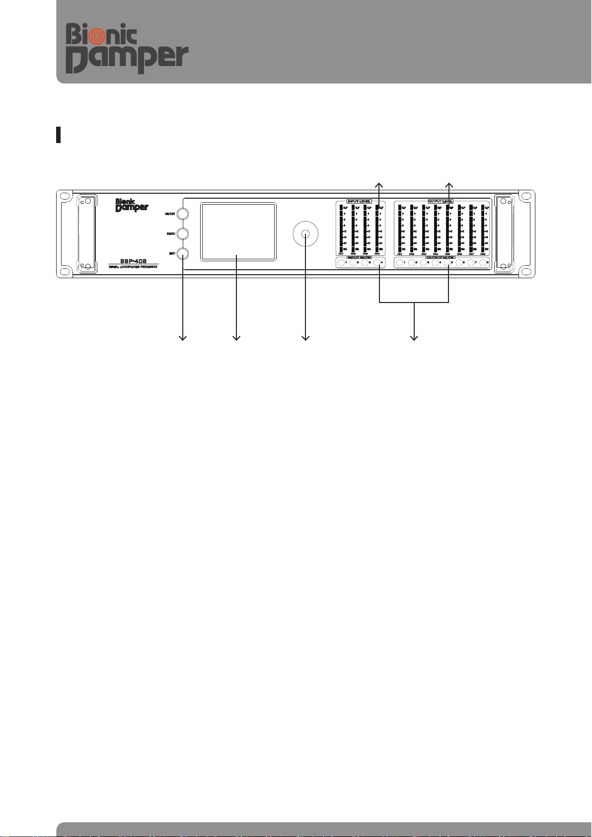
Front Panel Functions
④ ⑤
① ② ③
① Mode Buttons
There are three keys:
•METER Key: show the information of gain and routing status
•MENU Key: go to menu screen for device’s parameter set-up
•ESC Key: move to previous menu
② 3.5” Touch LCD Display
Integrated 3.5” color touch screen LCD with backlight, controls setup and operation. The LCD control
screen and its controls let the user adjust the configuration of unit and variable function parameters.
③ Rotary Encoder Wheel
Move to menu or edit parameter data values. When you edit a parameter, press the center of wheel to
confirm it after you finish editing.
④ Input Signal Level Indicators
Indicate the current input peak level of signal. The red segment indicates that the channel’s signal reaches
the one set of audible clipping, which should avoid by adjusting the input level.
⑥
⑤ Output Signal Level Indicators
Indicate the current output peak level of signal. The red segment indicates that the channel’s signal reaches the one set of audible clipping, which should avoid by adjusting the output level.
⑥ Mute On/Off Buttons
Mute or Un-Mute input and output channels. When an each channel is muted, a blue LED will come on for
indication.
06
DIGITAL LOUDSPEAKER PROCESSOR
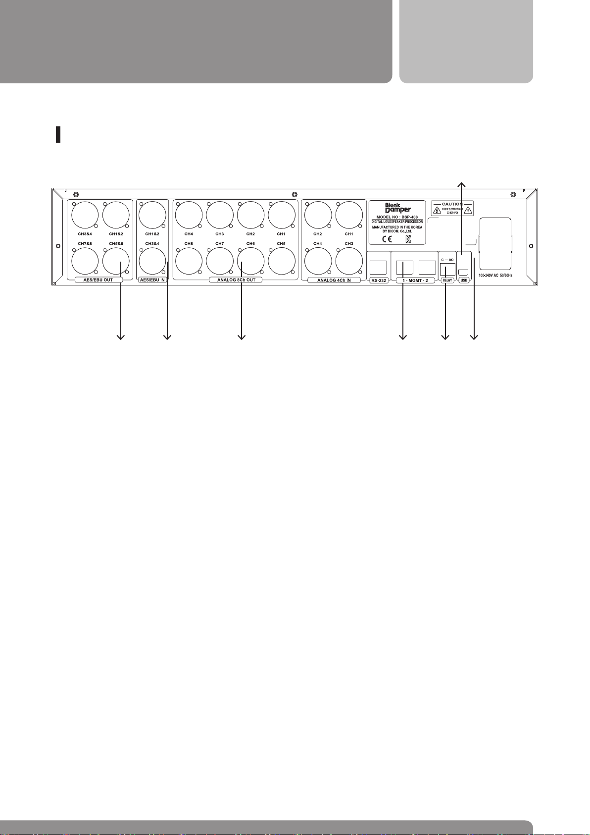
Rear Panel Functions
BSP - 408
⑨
①⑥ ⑤ ③⑦ ④⑧
②
① Main Power Unit
Turn the device power on/off. AC main input to the universal switched mode power supply, operates over a wide range of AC input voltages from 100V to 240V, 50/60Hz. Main Fuse is located
in a finger-proof holder adjacent to the mains inlet and its spec is 2.5A-250V.
② Control Input
The control input (Normal Open type) can be used to receive signals from third party equipment
that must trigger actions. This control input can also be used for audio mute action with emer
gency alarm equipment.
③ MGMT Ethernet Port
This Ethernet Port is a standard RJ45 CAT5 connector, used for transmission of remote control
data over long distance or multiple unit applications and allows setup device function by PC
control program. MGMT In & out Ports allow daisy-chain connection of multiple unit.
④ RS-232 Control Port
Used for system condition checking for only special engineers.
-
⑤ Balanced XLR Analog Input
Received electrically balanced audio signal, locking XLR connector
⑥ Balanced XLR Analog Output
Output electrically balanced audio signal to the system’s amplifiers.
07

⑦ Digital Input terminal
Receives AES/EBU digital input signal. This connection is wired like the audio analog connection,
but we recommend the use of the proper thress conductor, 110-Ohm, twisted pair cable.
⑧ Digital Output terminal
Send AES/EBU digital output signal.
⑨ USB Control terminal
Connect USB terminal to PC and allows setup device function by PC control program.
08

MENU TREE
METER INPUT STATUS
OUTPUT STATUS
DIGITAL LOUDSPEAKER PROCESSOR
BSP - 408
MENU INPUT
OUTPUT
INPUT
SELECT
GAIN
GRAPHIC EQ
PARAMETRIC EQ
DELAY
MATRIX ROUTE
OUTPUT ROUTE
GAIN
BAND PASS
FILTER
: select OUTPUT 8
channels
: 4CH ANALOG, AES/EBU INPUT set-up
: 4 INPUT channels GAIN value set-up
: 4 INPUT channels 31 Band frequency GAIN set-up
: 4 INPUT channels 9 Band frequency filter time and frequency GAIN set-up
: 4 INPUT channels delay time set-up (Time period set-up)
: Set up OUTPUT 8 channel as for 4 INPUT channels
: 8 channels ANALOG, AES/EBU OUTPUT set-up
: OUTPUT 8 channels GAIN value set-up
FIR
LOW, HIGH, frequency
set-up
TAB number set-up
FC (central frequency)
set-up
IIR
LOW, HIGH, frequency
set-up
SLOPE: LO/HI selection
FC (central frequency)
set-up
SYSTEM
CONFIG
PHASE set-up
POLARITY set-up
GRAPHIC EQ
PARAMETRIC EQ
: Product information identification ( (IP, MAC ADDRESS, program VERSION)
: PRESET saved value: delete/save/LOAD → save up to TOTAL 50
: OUTPUT 8 channels 31 BAND frequency Gain set-up
: OUTPUT 8 channels 9BAND frequency filter time and frequency gain set-up
09
PHASE set-up
POLARITY set-up

Set-up modification and method
< BSP-408 LCD set-up screen >
Set-up modification is done by LCD touch and the application is immediately executed. Also, when the Lock key
is turned on at the LCD screen, no modification of any data value is unavailable. In this case, turn off ‘Lock’
to modify any data value.
1) Lock set-up and activation, deactivation, OFF set-up
A.
Click‘ ’ key for 3 seconds and it is conversed into‘Lock’status.
B. This is the image of ‘Lock’ status. Click ‘ ’key for 3 seconds again and‘Lock’status is can-
celled.
C. This is the image of activated status (function is being applied). Click once again to converse into dea
tivated status.
D. This is the image of deactivated status (function is suspended from application). Click once again to
converse into activated status.
E. This is ‘OFF’ status which means all of band functions are suspended from use at P-EQ and click for
two seconds to cancel OFF status. (Click for two seconds once again to converse into ‘OFF’ status.)
2) INPUT set-up
2-1) INPUT SELECT set-up
10

DIGITAL LOUDSPEAKER PROCESSOR
BSP - 408
A. Select MENU → INPUT → INPUT SELECT.
B. This screen is to route the input source selected willingly from 4 sound source inputs on LCD screen
(you may set up analog or digital input into the input port you want).
2-2) INPUT GAIN set-up
A. Select MENU → INPUT → GAIN
11

B. On the Gain set-up screen and at the input to control its volume (IN 1~4), click or button to modify
the sound GAIN.
2-3) INPUT GRAPHIC EQ set-up
A. Select MENU → INPUT → GRAPHIC EQ
B. On the INPUT G-EQ set-up screen, select the input channel you want (CH 1 ~ CH4). Then, click or
button to modify the sound GAIN.
2-4) INPUT PARAMETRIC EQ set-up
12

DIGITAL LOUDSPEAKER PROCESSOR
BSP - 408
A. Select MENU → INPUT → PARAMETRIC EQ.
B. Select the input channel (CH1~CH4) you want on the INPUT P-EQ set-up screen and set the frequency
filter you want among , or ( or ).
C. Select any Band (1~9) you want among 9 Band Parametric EQ. then select the value of Fc (Central frequency), Gain, and Q (Slope) and set up the value you want by clicking button or number buttons.
2-5) INPUT DELAY set-up
13

A. Select MENU → INPUT → INPUT DELAY.
B. On the INPUT DELAY set-up screen, select the input channel you want (CH1~CH4) and set up the Meter
you want by clicking buttons or number buttons.
3) OUTPUT set - up
3-1) OUTPUT MATRIX set-up
A. Select MENU → OUTPUT → MATRIX ROUTE.
B. Set up the output port (OUT 1~8) as for input (IN 1~4) source. Select and click the input and output you
want on the LCD screen then a(
) appears. Click once more if you cancel or set by error, then this image
14

disappears and it will be cancelled.
3-2) OUTPUT ROUTE set-up
DIGITAL LOUDSPEAKER PROCESSOR
BSP - 408
A. Select MENU → OUTPUT → OUTPUT ROUTE
B. Set which number of device port to send analog/digital output as for the OUTPUT channel as the
output set-up.
- Select the output port to set up (Out CH 1~8) and ANA or AES. Then select the port to send output
and the audio output is transmitted to the output port you selected (1~8).
3-3) OUTPUT GAIN set-up
15

A. Select MENU → OUTPUT → GAIN
B. On the Gain set-up screen and at the out to control its volume (OUT 1~8), click or button to modify
the sound GAIN.
3-4) OUTPUT BPF(Band Pass Filter) set-up
A. Select MENU → OUTPUT → BPF.
B. Select the OUTPUT channel to set up on BPF set-up screen.
16

DIGITAL LOUDSPEAKER PROCESSOR
BSP - 408
C. Select the filter to set up on BPF set-up screen.
D-1. The FIR function set-up screen appears if you select FIR filter.
① Set-up the standard frequency to filter LOW part frequency.
② Set-up the standard frequency to filter HIGH part frequency.
③ Click ‘slope’ button to activate and set up the LOW and/or HIGH value you want of SLOPE filter
‘bs6’ or ‘lr48’.
④ Click button to move to the next screen.
⑤ Set-up Fc standard frequency by button or number buttons.
⑥ Set-up PHASE by button or number buttons.
⑦ Set-up POLARITY.
E-2. The IIR set-up screen appears if you select IIR filter.
① Set-up the standard frequency to filter LOW part frequency.
② Set-up the standard frequency to filter HIGH part frequency.
③ Click button to activate and set up the LOW and/or HIGH value you want of SLOPE filter
or .
④ Click button to move to the next screen.
⑤ Set-up Fc standard frequency by button or number buttons.
⑥ Set-up PHASE by button or number buttons.
⑦ Set up POLARITY.
17

3-5) OUTPUT GRAPHIC EQ set-up
A. Select MENU → OUTPUT → GRAPHIC EQ.
B. On the OUTPUT G-EQ set-up screen, select the output channel you want (CH1~CH8) and the frequency
band among 31Band frequencies to control the sound GAIN.
3-6) OUTPUT PARAMETRIC EQ set-up
18

DIGITAL LOUDSPEAKER PROCESSOR
BSP - 408
A. Select MENU → OUTPUT → PARAMETRIC EQ.
B. Select the output channel (CH1~CH8) you want on the OUTPUT P-EQ set-up screen and set the frequency
filter you want among , or ( or ).
C. Click button and select any Band (1~9) you want among 9 Band Parametric EQ.
then select the value of Fc (Starting frequency), Gain, and Q (Slope) and set up the value you want by
clicking buttons or number buttons.
D. Click button and , Then select any Band (1~9) you want among 9 Band Parametric EQ.
then select the value of Fc (Starting frequency), Gain, and Q (Slope) and set up the value you want by
clicking buttons or number buttons.
3-7) OUTPUT DELAY set-up
19

A. Select MENU → OUTPUT → OUTPUT DELAY.
B. On the OUTPUT DELAY set-up screen, select the output channel you want (CH1~CH8) and set up
the Meter you want by clicking buttons or number buttons.
3-8) OUTPUT LIMITER set-up
A. Select MENU → OUTPUT → OUTPUT LIMITER
B. Select the output channel you want on the OUTPUT LIMITER set-up screen (CH1~CH8), then set up THSD,
ATK, and RLS function by the order.
① THSD (Threshold: Limit of sound): Activate
button and click buttons or number buttons to
set up GAIN value.
② ATK (ATTACK TIME: time to lower below the limit of sound): Activate button and click but-
tons or number buttons to set up TIME value.
③ RLS (RELEASE TIME: set up the time of return): Activate button and click buttons or number
buttons to set up TIME value.
20

DIGITAL LOUDSPEAKER PROCESSOR
BSP - 408
4) SYSTEM set-up
A. Select MENU → SYSTEM
① You may identify system name, IP, GATEWAY, SUBNET MASK, and MAC ADDRESS.
② Click to check system version.
5) CONFIG set-up
A. Select MANU → CONFIG → PRESET
B. Select PRESET (set-up value) delete, save or load and save in between 1~50.
① DELETE: To delete the saved PRESET value.
② SAVE: To save the present set-up value at PRESET (up to 50).
③ LOAD: To load the saved value and perform simply with the set-up value.
21

Specification and Function
Classification Details SPEC
Internal Sampling Rate 96KHz
A/D, D/A
Performance
Analog
Input
Processing
Output
Processing
Connetors
Control
Power
LCD
General
A/D, D/A Bit Resolution 24Bit
Dynamic Range 115dB (@A-weight)
Inputs and outputs 4 Input, 8 Outputs
Input Impedance 20KΩBlanced
Maximum Input Level 20dBu (@0dB input Gain)
THD+N < 0.002%(0dB, 1Khz)
Frequecny Response 20~20KHz(≤0.25dB)
Interchannel Crosstalk -100dB(@0dB, 1Khz)
Digital Interface
(AES/EBU)
GEQ/CH 31Band( +15dB ~ -15dB Range)
PEQ/CH 9Band (Bell, Hi-Shelf, Lo-Shelf Support)
Input Routing Support
Input Delay 1300msec (10usec period)/Ch
GEQ/CH 31Band( +15dB ~ -15dB Range)
PEQ/CH 9Band (Bell, Hi-Shelf, Lo-Shelf Support)
X-over Provide up to 1X2,1X3,1X4
Filter
Polarity Positive/Negative
Phase Control 0~ 179도 (by 5 degree)
Output Delay 1300msec (10usec period)/Ch
Compress/Limit
Analog/Digital Input 3Pin Female XLR
MGMT 100 Base-T (RJ45 2port)
Console RS232 (RJ45 1port)
Operation Voltage 100~240V AC (50/60Hz)
Power Cousumption < 30W maximum
LCD type/ inch 3.5 Inch Full Color LCD (Touch Support)
Dimension 480mmX305mmX88mm (2U) Rackmountable
Weight 5.5 Kg
Buttor-worth 12,18,24,36,48 dB/oct
Linkwitz-Riley 12,18,24,36,48 dB/oct
FIR Filter (Max 1100 Tabp/sharr All)
Release Time : X2,4,8,16,32 Attack time
4 Inputs, 8 Outputs
Up to 96KHz
Bessel 12,18,24,36,48 dB/oct
-20dBu ~ +20dBu Thereshold
Attack Time : 0.3m~ 100msec
22

DIGITAL LOUDSPEAKER PROCESSOR
BSP - 408
About Warranty
This product is warranted against detects in components and workmanship only, for a period of two years
from the date or shipment to the end user. During the warranty period, BICOM will, at its discretion, either
repair or replace products that prove to be defective, provided that the product is returned, shipping prepaid,
to an authorized BICOM service facility. Defects caused by unauthorized modification, misuse, negligence,
accident, or any use of this product that is not.
In accordance with the instructions provided by BICOM, are not covered by this warranty. This warranty is
exclusive, and no other warranty is expressed or implied. This warranty does not affect the customer’s sat
isfactory rights.
-
23

BSP-408
www.ibicom.net
Headquarter and plant
50 Gwajeong-ro 348 gil, Yeonje-gu, Busan, South Korea
TEL : +82 (51) 867-3700 / FAX : +82 (51) 853-9588
Operating headquarter
112 Jandari-ro, Mapo-gu, Seoul, South Korea
TEL : +82 (2) 336-0336 (ext. 300) / FAX : +82 (2) 336-0076
MADE IN KOREA
BSP-408-R0
 Loading...