

Benutzerhandbuch / User’s Manual
UPSI-B-2410
USV-Systeme
Industrie-PC-Netzteile
Netzteile
Medizintechnik
DC/DC-Wandler
USV-Systeme

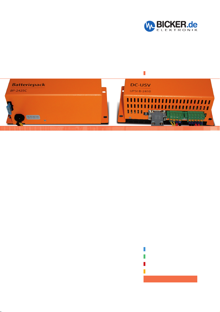
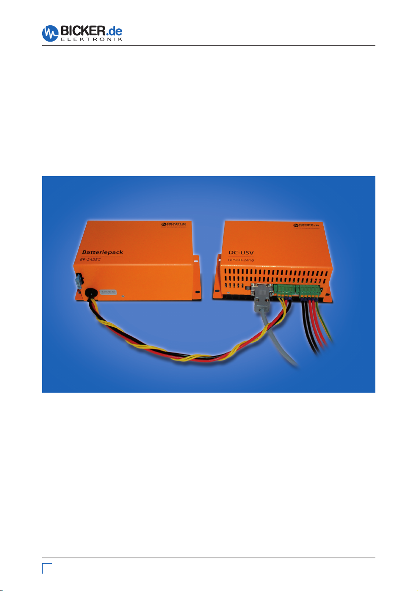
BP-2425C, optionales Zubehör
UPSI-B-2410

Benutzerhandbuch UPSI-B-2410
1 Allgemeines und Hinweise ......................................... 5
1.1 Lieferumfang .................................................................................. 5
1.2 Optional erhältliches Zubehör ................................................. 5
2 Technische Daten .................................................... 6
3 Funktionsprinzip ..................................................... 8
3.1 Netz-Betrieb .................................................................................... 8
3.2 Batterie-Betrieb ............................................................................. 8
4 LED-Anzeige .............................................................9
5 Montage und Inbetriebnahme ............................ 10
5.1 DC-Stecker1 .................................................................................. 11
5.2 DC-Stecker2 .................................................................................. 11
5.3 Schnittstelle 9-polig Sub-D ..................................................... 12
5.4 RUPS2000 OEM (USV-Softwarepaket) ................................. 13
5.5 Besonderes Verhalten der UPSI-B-2410 ............................. 14
6 Ausschalten manuell
7 Fehlerbehebung .................................................. 15
Bicker Elektronik GmbH
||
Tel. +49 (0)906 70595-0
(ohne USV-Management-Software)
||
www.bicker.de
||
info@bicker.de
14
3
Benutzerhandbuch UPSI-B-2410
4
Bicker Elektronik GmbH
||
Tel. +49 (0)906 70595-0
||
www.bicker.de
||
info@bicker.de

Benutzerhandbuch UPSI-B-2410
1 Allgemeines und Hinweise
Herzlichen Glückwunsch zu Ihrer neuen UPSI-B-2410!
Dieses Handbuch soll Sie mit den Komponenten und Eigenschaften der DC-USV
UPSI-B-2410 vertraut machen. Wir haben alle Sorgfalt walten lassen, um in diesem
Handbuch vollständige und genaue Informationen über unser Produkt zu liefern. Für
möglicherweise vorhandene Fehler kann jedoch keine Haftung übernommen werden. Hinweise auf vorhandene Fehler, Verbesserungsvorschläge und Kritik nehmen
wir dankbar entgegen.
Hi n we is e
Die Installation und Inbetriebnahme darf nur von entsprechend qualifiziertem
Fachpersonal durchgeführt werden.
Dabei sind die jeweiligen Vorschriften einzuhalten!
Am Eingang ist eine 15-A-Sicherung vorzuschalten!
Alle Anschluss-Leitungen müssen dem max. Eingangsstrom der UPSI-B-2410
(12,5 A) entsprechend dimensioniert und gesondert abgesichert werden.
Der empfohlene Querschnitt für die Anschluss-Leitungen ist 2,5 mm
Bei Verpolung kann die USV und die angeschlossene Last Schaden nehmen.
Der Batteriepack BP-2425C sollte bei Einlagerung oder Nicht-Benutzung alle
6 Monate mit der DC-USV UPSI-B-2410 nachgeladen werden.
2
.
1.1 Lieferumfang
DC-USV UPSI-B-2410
Anschluss-Steckverbinder, Phoenix Contact, 5-polig
Handbuch
1.2 Optional erhältliches Zubehör
Batteriepack BP-2425 C inkl. Anschluss-Steckverbinder, Phoenix Contact, 4-polig
RUPS 2000 OEM, USV-Management-Software
Schnittstellen-Kabel 9-polig SUB-D
Bicker Elektronik GmbH
||
Tel. +49 (0)906 70595-0
||
www.bicker.de
||
info@bicker.de
5

Benutzerhandbuch UPSI-B-2410
2 Technische Daten der DC-USV UPSI-B-2410
Te ch ni s ch e Da t e n
Eingangsspannung 24 V DC (20…36 V)
Eingangsstrom 12,5 A max.
Ausgangsspannung Im Normalbetrieb: ca. 0,4 V unterhalb der Eingangsspan.
Im Batteriebetrieb: ca. 30,9…19 V DC
Ausgangsstrom 10 A max.
Batterieladestrom 2 A max. (interner Batterielader)
Ladeschluss-Spannung 26,4…31,2 V, temperaturabhängig
Tiefentladeschutz 19 V DC ±2 %
Batterie schwach (Batterie-Betrieb) <21 V ±2 %
Umschaltzeit / -schwellen 0 ms, Online-Technologie, Netz/ BAT 20 V, BAT /Netz 22 V
Überbrückungszeit Siehe Datenblatt Batteriepack BP-2425C
Schnittstelle DSUB9-Buchse, Open-Kollektor, potentialgetrennt für
Ausgänge: Power Fail, Battery Low Eingang: Shutdown
Optional auch mit USV-Software zur Anbindung an
gängige Betriebssysteme möglich
Batterietyp Blei-Zinn-Batterie, wartungsfrei
Sicherheit / EMV CE
Umgebungstemperaturbereich -30…+70 °C
Lagertemperaturbereich -40…+80 °C
Lagerfeuchtigkeit 0…95 %, nicht kondensierend
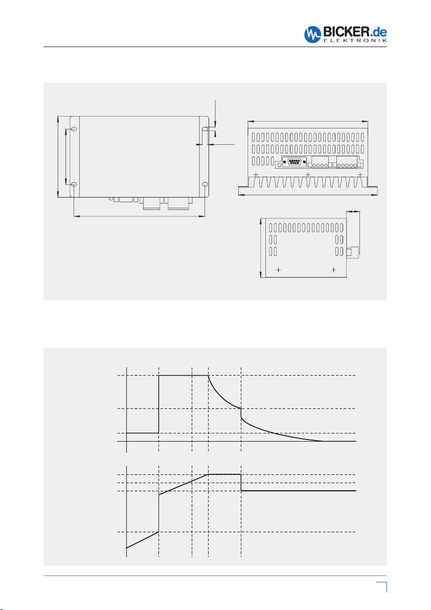
Abmessungen 182 x 102 x 73 mm ±0,5 mm
Gewicht 0,75 kg
Pr od uk t sp e zi f is c he An ga be n
LED-Anzeige 3-Farben-LED für „Power ok” (grün), „Power Fail” (orange), „Battery low”
(rot/orange blinkend) und „Batterie defekt” (rot/grün blinkend)
Batterieüberwachung Batterietest erfolgt im Normalbetrieb alle 10 Minuten
Eigenverbrauch ca. 150 mA
Betriebshöhe max. 12 000 Fuß, Betrieb
Shutdown- Das Shutdown-Signal wird in der Startphase des Systems für ca. 2 Minuten
Unterdrückung unterdrückt.
Reboot-Funktion Kehrt während eines Netzausfalls und der schon eingeleiteten Shutdown-
Phase von Windows® die Netzspannung wieder zurück, so „hängt” das
Betriebssystem mit der Meldung „Sie können den PC jetzt ausschalten“.
Die Reboot-Funktion hingegen schaltet das System nach erfolgtem
Shutdown aus und nach ca. 5 Sek. wieder ein.
6
Bicker Elektronik GmbH
||
Tel. +49 (0)906 70595-0
||
www.bicker.de
||
info@bicker.de
Benutzerhandbuch UPSI-B-2410
Zeichnung UPSI-B-2410
5,00 mm
7,00 mm
70,00 mm
103,00 mm
166,00 mm
75,00 mm
152,00 mm
176,00 mm
Toleranz ±0,5 mm
Präzise Ladungssteuerung durch Mikrocontroller, Ladekennlinie
Batterieladestrom
Schnell-Ladung
Umschaltung auf
Erhaltungsladung
17,00 mm
Trickle Charge
Ladespannung
Ladespannung
Ladeschlussspannung
Umschaltung
auf Schnell-Ladung
Bicker Elektronik GmbH
I
V
||
Tel. +49 (0)906 70595-0
||
www.bicker.de
||
info@bicker.de
7

Benutzerhandbuch UPSI-B-2410
3 Funktionsprinzip
Bei einem Ausfall der Netzversorgung versorgt die DC-USV UPSI-B-2410 den angeschlossenen Verbraucher mit einer DC-Spannung aus dem angeschlossenen Batteriepack. Über die LED-Anzeige wird der Status optisch angezeigt. Per Schnittstelle
können Signale an einen angeschlossenen PC gemeldet werden.
Quelle:
z. B. AC/DC-Netzteil
AC
DC
15 A
DC-USV
UPSI-B-2410
Batterie-
pack
BP-2425C
Verbraucher
(PC)
Schnittstelle
3.1 Netz-Betrieb
Im Netz-Betrieb liefert eine vorgeschaltete Spannungsquelle 24V DC. Diese Spannung
abzüglich 0,4 VDC liegt direkt am Verbraucher (z. B. PC) an. Der angeschlossene
Batteriepack wird von der UPSI-B-2410 geladen. Die LED leuchtet grün und die
Schnittstelle signalisiert „Power ok“. Etwa alle 10 Minuten wird ein Batterietest durchgeführt. Bei defektem Akku oder z. B. nicht angeschlossenem Batteriepack blinkt die
LED rot/grün.
3.2 Batterie-Betrieb
Sinkt die Versorgungsspannung am Eingang der DC-USV UPSI-B-2410 unter die
Umschalt spannungsschwelle, übernimmt die UPSI-B-2410 die Versorgung der angeschlossenen Verbraucher. Die LED leuchtet orange und die Schnittstelle signalisiert „Power Fail“. Lässt die Kapazität des angeschlossenen Batteriepacks nach
(Batteriespannung sinkt auf <21 V), so signalisiert die Schnittstelle „Batterie Low“. Die
LED blinkt rot/orange. Durch einen Impuls auf den „Shutdown“-Eingang kann die
DC-USV UPSI-B-2410 abgeschaltet werden.
8
8
Bicker Elektronik GmbH
||
Tel. +49 (0)906 70595-0
||
www.bicker.de
||
info@bicker.de
Benutzerhandbuch UPSI-B-2410
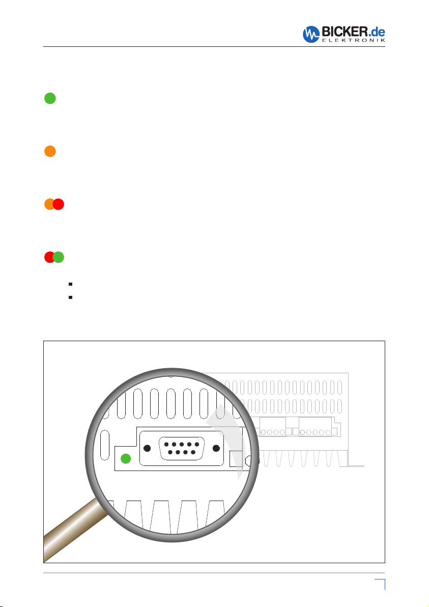
4 LED-Anzeige
LED grün:
Die LED leuchtet grün, solange eine Eingangsspannung (>20 V DC)
vorhanden ist.
LED orange:
Die LED leuchtet orange, sobald die DC-USV UPSI-B-2410
in den Batterie-Betrieb schaltet (Eingangsspannung <20 V DC).
LED rot/orange blinkend:
Die LED blinkt im Batterie-Betrieb rot/orange, wenn die Kapazität des
angeschlossenen Batteriepacks abnimmt (Batteriespannung sinkt auf <21 V).
LED rot/grün blinkend:
Die LED blinkt rot/grün, wenn
der angeschlossene Akku tief entladen oder defekt ist.
die Batteriezuleitung oder Sicherung defekt ist.
Bicker Elektronik GmbH
||
Tel. +49 (0)906 70595-0
||
1 2 3 4
www.bicker.de
||
1 2 3 4 5
info@bicker.de
99

5 Montage und Inbetriebnahme
Anschlussbild
Benutzerhandbuch UPSI-B-2410
DC-Stecker 1
1 Temp.-Fühler Batt.
2 Temp.-Fühler Batt.
3 Batterie (+)
4 Batterie (-)
Batteriepack
BP-2425C
Hinweis: Am Eingang (F1) und Ausgang (F2) wird empfohlen, bauseits eine Sicherung vorzuschalten.
1 2 3 4
1 2 3 4 5
DC-USV
UPSI-B-2410
15 A
+
–
Schnittstelle
Eingang (+)
Eingang (–)
PC
Verbraucher
DC-Stecker 2
1 Ausgang (–)
2 Eingang (–)
3 Ausgang (+)
4 Eingang (+)
5 Erde
Ac h tu ng
Die DC-USV UPSI-B-2410 sowie der Batteriepack BP-2425C dürfen nicht
kopfstehend montiert werden.
Es ist sicherzustellen, dass im Betrieb eine ausreichende Konvektion möglich ist.
40 mm
20 mm
40 mm
Es sind die Abstände
wie in nebenstehendem Bild
einzuhalten!
20 mm
40 mm
Für den Batteriepack BP-2425C sind keine Abstände bei der Montage einzuhalten!
10
10
Bicker Elektronik GmbH
||
Tel. +49 (0)906 70595-0
||
www.bicker.de
||
info@bicker.de

Benutzerhandbuch UPSI-B-2410
Hi n we is e
Der DC-Eingang (DC-Stecker 2, PIN 4) muss mit einer 15-A-Sicherung
abgesichert werden.
Beim Anschluss des Batteriepacks BP-2425C und der Ein- und Ausgänge
ist auf die richtige Polarität zu achten!
Vor dem Einschalten ist die ordnungsgemäße Verkabelung sicherzustellen. Alle
Sicherungen müssen gesteckt sein, insbesondere auch die des Batteriepacks.
5.1 DC-Stecker 1:
Anschluss Batteriepack
An diesen Steckverbinder wird der Batteriepack BP-2425C angeschlossen.
Nur mit diesem Batteriepack kann die DC-USV UPSI-B-2410 im Temperaturbereich
von -30…+70 °C eingesetzt werden.
PIN
1 Temperatur-Fühler Batterie
2 Temperatur-Fühler Batterie
3 Batterie (+)
4 Batterie (-)
5.2 DC-Stecker 2:
Anschluss Ein- und Ausgang
Der Anschluss-Steckverbinder (4-polig)
ist im Lieferumfang des Batteriepacks
BP-2425C enthalten.
Temp Temp BAT+BAT
–
PIN
1 Ausgang (–)
2 Eingang (–)
3 Ausgang (+)
4 Eingang (+)
5 Erde
Die Ausgangsspannung folgt der angeschlossenen
Eingangs spannung abzüglich 0,4 VDC. Der AnschlussSteck ver binder (5-polig) ist im Lieferumfang der DC-USV
UPSI-B-2410 enthalten.
OUT–IN–OUT+IN
+
Bicker Elektronik GmbH
||
Tel. +49 (0)906 70595-0
||
www.bicker.de
||
info@bicker.de
1111

Benutzerhandbuch UPSI-B-2410
5.3 Schnittstelle 9-polig Sub-D
PIN PIN
1 n.c. 6 Shutdown Eingang
2 Power Fail (Kollektor) Ausgang 7 Bezug Shutdown
3 n.c. 8 n.c.
4 Bezug Power Fail, Batterie Low (Emitter) 9 n.c.
5 Batterie Low (Kollektor) Ausgang
Power Fail
Im Netz-Betrieb ist die Kollektor-Emitter-Strecke des Optokopplers nicht „leitend“. Im
Batterie-Betrieb (Eingangsspannung <20 V DC) ist die Kollektor-Emitter-Strecke des
Optokopplers „leitend“.
Batterie Low
Im Netz-Betrieb ist die Kollektor-Emitter-Strecke des Optokopplers nicht „leitend“.
Im Batterie-Betrieb und schwacher Batteriespannung (<21 V DC) ist die KollektorEmitter-Strecke des Optokopplers „leitend“.
Shutdown
Bei Anlegen einer Spannung während des Batterie-Betriebs und nach Ablauf von
2 Minuten Shutdown-Unterdrückung (Punkt 5.5) von +5...24 VDC an PIN6, schaltet die
UPSI-B-2410 nach ca. 5 Sekunden ab.
12
12
UPSI-B-2410
Schnittstelle
Bicker Elektronik GmbH
(+)
Power Fail
PIN2
Power Fail (Bezug)
PIN4
||
Tel. +49 (0)906 70595-0
Für einen digitalen Ausgang (SPS)
kann ein „Pull-UP“-Widerstand
be-rechnet werden.
Daten Optokoppler:
Uce 24 V DC
Ice 0,1 Amax
P 0,1 Wmax
||
www.bicker.de
||
info@bicker.de

Benutzerhandbuch UPSI-B-2410
5.4 RUPS 2000 OEM (USV-Softwarepaket)
Das USV-Softwarepaket unterstützt die folgenden Windows®-Betriebssysteme:
3.1, 98, NT, ME, 2000, 2003, XP und Vista (andere OS auf Anfrage). Die Open
Kollektorschnittstelle des DC-USV-Moduls UPSI-B-2410 ist für die Software RUPS 2000
OEM konzipiert. Diesem Softwarepaket liegt ein rotes Schnittstellen-Kabel (M2501)
bei. Damit kann die UPSI-B-2410 mit einem freien COM-Port eines angeschlossenen
PC’s verbunden werden.
Wichtige Grundeinstellungen
General >> COM Port am PC
E-Mail >> E Mail-Versand über externen E-Mail-Server (nicht im Lieferumfang)
Pager >> Pager-Information über optionales Modem (nicht im Lieferumfang)
Shutdown >> Überbrückungszeit, automatisches Speichern von Dateien,
USV abschalten. Die Überbrückungszeit kann ab Version 3.21 in
0,1-Minutenschritten (6 Sek.) eingestellt werden.
Warnings >> Pop-Up Warnmeldungen
Bicker Elektronik GmbH
||
Tel. +49 (0)906 70595-0
||
www.bicker.de
||
info@bicker.de
13

Benutzerhandbuch UPSI-B-2410
5.5 Besonderes Verhalten der UPSI-B-2410
Reboot-Funktion
Kehrt während eines Netzausfalls und der schon eingeleiteten Shutdown-Phase von
Windows® das Netz wieder zurück, so „hängt“ das Betriebssystem mit der Meldung:
„Sie können den PC jetzt ausschalten“. Die Reboot- Funktion schaltet das System nach
erfolgtem Shutdown aus und nach ca. 5 Sek. wieder ein.
Es ist kein Bedienereingriff notwendig.
Shutdown Unterdrückung
Das Shutdown-Signal wird in der Startphase des Systems für ca. 2 Minuten unterdrückt, da eine eventuelle Schnittstellenprüfung von Windows und einem zeitgleichen
Netzausfall das Modul sonst abschalten würde. Diese Unterdrückung ist nur beim
ersten Einschalten des Moduls aktiv!
6 Ausschalten manuell (ohne USV-Management-Software)
Nach dem Abschalten der Eingangsspannung wird die angeschlossene Last weiterhin von der angeschlossenen Batterie versorgt. Soll diese Batteriespannung auch
abgeschalten werden, muss die Sicherung des Batteriepacks nach Abschalten des
Verbrauchers herausgenommen werden.
14
Bicker Elektronik GmbH
||
Tel. +49 (0)906 70595-0
||
www.bicker.de
||
info@bicker.de

Benutzerhandbuch UPSI-B-2410
7 Fehlerbehebung
Kein Batterie-Betrieb
Leitungsbruch oder Sicherungsdefekt auf der Batterieseite
Kein Batteriepack angeschlossen
Batteriepack hat nicht genügend Kapazität oder ist entladen
Batteriepack oder Versorgungsspannung verpolt >> Eingangssicherung erneuern
LED blinkt rot/grün
Leitungsbruch oder Sicherungsdefekt auf der Batterieseite
Kein Batteriepack angeschlossen
Die UPSI-B-2410 schaltet in Verbindung mit RUPS 2000 OEM nicht ab.
Das Häkchen unter „
wurde nicht gesetzt.
Die Shutdown-Unterdrückungszeit (Punkt 5.5) wurde nicht abgewartet, und
somit wurde der Shutdown-Impuls „unterdrückt“.
Das Schnittstellenkabel ist defekt oder ein falsches Schnittstellenkabel wurde
verwendet.
Settings
“, „
Shutdown
“ und
„USV abschalten
“
Batterie wird nicht voll geladen
Temperaturfühler kurzgeschlossen oder unterbrochen
Batteriepack defekt
Keine Funktion
Eingangsspannung verpolt? >> Eingangssicherung erneuern
Eingangssicherung defekt? >> Eingangssicherung erneuern
Leitungsquerschnitt zu „klein“? >> Empfohlener Leitungsquerschnitt 2,5 mm
Der Überspannungsschutz am Eingang (ab 40 V DC) hat angesprochen.
2
Die interne Supressor-Diode schließt kurz und die Eingangssicherung löst aus.
Dabei geht das UPSI-B-2410 in Batterie-Betrieb. >> Eingangssicherung erneuern
Bicker Elektronik GmbH
||
Tel. +49 (0)906 70595-0
||
www.bicker.de
||
info@bicker.de
15

BP-2425C, optional accessory
UPSI-B-2410

User’s Manual UPSI-B-2410
1 General Information and Safety Warnings ............... 5
1.1 Contents of Delivery .................................................................... 5
1.2 Optional Accessories ................................................................... 5
2 Technical Data ......................................................... 6
3 Functional Description ........................................... 8
3.1 Mains Mode .................................................................................... 8
3.2 Battery Mode .................................................................................. 8
4 LED Display ...............................................................9
5 Installation and Commissioning .......................... 10
5.1 DC Connector 1 ........................................................................... 11
5.2 DC Connector 2 ........................................................................... 11
5.3 Interface 9-pole Sub-D .............................................................. 12
5.4 RUPS2000 OEM (UPS Software Package) ........................... 13
5.5 Special Features of the UPSI-B-2410.................................... 14
En gl ish
6 Manual Switch-Off
7 Troubleshooting ................................................. 15
Bicker Elektronik GmbH
||
Tel. +49 (0)906 70595-0
(without UPS Management Software) .
||
www.bicker.de
||
info@bicker.de
14
17

User’s Manual UPSI-B-2410
En gl ish
18
Bicker Elektronik GmbH
||
Tel. +49 (0)906 70595-0
||
www.bicker.de
||
info@bicker.de

User’s Manual UPSI-B-2410
1 General Information and Safety Warnings
Congratulations for choosing the UPSI-B-2410!
This manual explains the components and properties of the DC UPS UPSI-B-2410. All
information contained in this manual has been revised thoroughly to ensure accuracy
and completeness. Yet Bicker Electronic accepts no liability for any omissions or faults.
We will appreciate any notifications regarding faults, suggestions for improvements
and criticism.
Sa f et y Wa rn in gs
Installation and connection must only be carried out by qualified personnel.
The relevant rules of electrical engineering must be observed!
A 15 A fuse must be installed at input line!
All connector cables must be dimensioned for the max. input current of the
UPSI-B-2410 (12.5 A) and an according additional protection must be provided.
The recommended cross section for the connector cables is 2.5 mm
A polarity reversal can damage the UPS as well as the connected load.
Charging the battery pack BP-2425C every six months with the DC UPS
UPSI-B-2410 is recommended during storage or when the battery pack
is not in use.
2
.
En gl ish
1.1 Contents of Delivery
DC UPS UPSI-B-2410
Pin-and-socket connector, Phoenix contact, 5-pole
Manual
1.2 Optional Accessories
Battery pack BP-2425C incl. pin-and-socket connector, Phoenix contact, 4-pole
RUPS 2000 OEM, UPS Management Software
Interface cable 9-pole SUB-D
Bicker Elektronik GmbH
||
Tel. +49 (0)906 70595-0
||
www.bicker.de
||
info@bicker.de
19

User’s Manual UPSI-B-2410
2 Technical Data of the DC-UPS UPSI-B-2410
Te ch ni c al d at a
Input voltage 24 V DC (20…36 V)
Input current 12.5 A max.
Output voltage Normal mode: app. 0.4 V below input voltage
Battery mode: app. 30.9…19 V DC
Output current 10 A max.
Battery charge current 2 A max. (internal battery charger)
Charging voltage 26,4…31,2 V, depending on temperature
En gl ish
Discharge protection of battery 19 V DC ±2 %
Battery Low <21 V ±2 % (Battery mode)
Transfer time / transfer limits 0 ms, online technology, Mains/BAT 20 V, BAT/Mains 22 V
Back up time See battery pack BP-2425C
Interface DSUB9 female, open collector, potential free for
Outputs: power fail, battery low Input: Shutdown
Optionally also with UPS software for connecting all
established operating systems
Type of battery Maintenance-free pure lead tin battery (PLT)
Safety / EMC CE
Operating temperature -30…+70 °C
Storage temperature -40…+80 °C
Operating humidity 0…95 %, non-condensing
Dimensions 182 x 102 x 73 mm ±0.5 mm
Weight 0.75 kg
Pr od uc t s pe ci fi c d at a
LED display 3 colour LED for ”Power ok” (green), ”Power Fail” (orange), ”Battery low”
(red/orange flashing) and ”Battery defect” (red/green flashing)
Battery monitoring Battery test is carried out every 10 minutes in normal mode
Power consumption App. 150 mA
Operating height Max. 12 000 feet above sea level
Shutdown- The Shutdown signal is disabled for about two minutes after startup.
Suppression
Reboot function If DC IN fails and main power returns during shutdown mode of
Windows®, the operating system will ‘lock’ with the message “Your PC is
now safe”. The reboot function restarts the system after about 5 seconds.
20
Bicker Elektronik GmbH
||
Tel. +49 (0)906 70595-0
||
www.bicker.de
||
info@bicker.de

User’s Manual UPSI-B-2410
Drawing UPSI-B-2410
70,00 mm
103,00 mm
166,00 mm
Tolerance ±0.5 mm
Exact charging via microcontroller
Charging current
Fast charge
Float charge
5,00 mm
152,00 mm
7,00 mm
176,00 mm
17,00 mm
En gl ish
75,00 mm
Trickle charge
Charging voltage
Charging voltage
End of charging
voltage
Start of
fast charging
Bicker Elektronik GmbH
I
V
||
Tel. +49 (0)906 70595-0
||
www.bicker.de
||
info@bicker.de
21

User’s Manual UPSI-B-2410
3 Functional Description
In case of a mains voltage failure the DC UPS UPSI-B-2410 supplies the connected
consumer load with DC voltage from the connected battery pack. Via LED display the
status is visualised. Signals can be informed to a connected PC via interface.
Source:
En gl ish
e. g. AC/DC power supply
AC
15 A
DC
DC UPS
UPSI-B-2410
Battery
pack
BP-2425C
Consumer
load (PC)
Interface
3.1 Mains Mode
In mains mode a voltage source at the input line supplies 24 V DC. This voltage minus
0.4 V DC is provided directly at the consumer load (e.g. PC). The connected battery
pack is charged by the UPSI-B-2410. The LED is green and the interface signalises
“Power ok“. App. every 10 minutes a battery test is carried out. In case of a defect
battery or if the battery pack is not connected, the LED flashes red/green.
3.2 Battery Mode
If the supply voltage drops below the switch-over threshold at the input of the
DC UPS UPSI-B-2410, the UPSI-B-2410 takes over supplying the connected consumer loads. The LED is orange and the interface signalises “Power Fail“. When the
capaci-tance of the connected battery pack decreases (battery voltage dropping to
<21 V), the interface signalises “Battery Low“. The LED flashes red/orange. The DC UPS
UPSI-B-2410 can be switched off by an impulse at the “Shutdown“ input.
22
Bicker Elektronik GmbH
||
Tel. +49 (0)906 70595-0
||
www.bicker.de
||
info@bicker.de

User’s Manual UPSI-B-2410
4 LED Display
LED green:
The LED is green as long as an input voltage (>20 V DC) is present.
LED orange:
The LED turns to orange as soon as the DC UPS UPSI-B-2410 switches
to battery mode (input voltage <20 V DC).
LED red/orange-flashing:
The LED flashes red/orange in battery mode when the capacitance of the
connected battery pack decreases (battery voltage dropping to <21 V).
LED red/green-flashing:
The LED flashes red/green
when the connected battery is discharged or defect.
when the battery supply line or fuse is defect.
1 2 3 4
En gl ish
1 2 3 4 5
Bicker Elektronik GmbH
||
Tel. +49 (0)906 70595-0
||
www.bicker.de
||
info@bicker.de
23

5 Installation and Commissioning
Connections
User’s Manual UPSI-B-2410
DC connector 1
1 Temp. sensor batt.
2 Temp. sensor batt.
3 Battery (+)
4 Battery (-)
En gl ish
Battery pack
BP-2425C
Note: Installing a fuse on site at both the input (F1) and output (F2) is recommended.
1 2 3 4
1 2 3 4 5
F1
(on site)
F2
(on site)
DC connector 2
1 Output (–)
2 Input (–)
3 Output (+)
4 Input (+)
5 GND
PC System
COM
At t en ti on
Do neither mount the DC UPS UPSI-B-2410 nor the battery pack BP-2425C
upside down.
Make sure sufficient convection is possible during operation.
40 mm
20 mm
40 mm
The distances illustrated
in the following figure
must be observed!
40 mm
For the battery pack BP-2425C
no distances have to be observed for the installation!
24
Bicker Elektronik GmbH
||
Tel. +49 (0)906 70595-0
||
www.bicker.de
||
20 mm
info@bicker.de

User’s Manual UPSI-B-2410
No t es
The DC input (DC connector 2, PIN 4) must be protected by a 15 A fuse.
Observe the correct polarity when connecting the battery pack BP-2425C
as well as the inputs and outputs!
Before switching on the unit, make sure all connections are correct.
All fuses, especially that of the battery pack, must be engaged.
5.1 DC Connector 1:
Battery pack connection
At this pin-and-socket connector the battery pack BP-2425C is connected.
Only with this battery pack the DC UPS UPSI-B-2410 can operate in the temperature
range of -30…+70 °C.
PIN
1 Temperature sensor battery
2 Temperature sensor battery
3 Battery (+)
4 Battery (–)
The (4-pole) pin-and-socket connector
is included in the delivery of battery
Temp Temp BAT+BAT
–
pack BP-2425C.
5.2 DC Connector 2:
Input and output connection
PIN
1 Output (–)
2 Input (–)
3 Output (+)
4 Input (+)
5 GND
The output voltage corresponds to the connected input
voltage minus 0.4 V DC.
The (5-pole) pin-and-socket connector is included in the
OUT–IN–OUT+IN
+
delivery of the DC UPS UPSI-B-2410.
En gl ish
Bicker Elektronik GmbH
||
Tel. +49 (0)906 70595-0
||
www.bicker.de
||
info@bicker.de
25

User’s Manual UPSI-B-2410
5.3 Interface 9-pole Sub-D
PIN PIN
1 n.c. 6 Shutdown input
2 Power Fail (collector) output 7 Shutdown reference
3 n.c. 8 n.c.
4 Reference Power Fail, Battery Low (emitter) 9 n.c.
5 Battery Low (collector) output
En gl ish
Power Fail
In mains mode, the collector-emitter-line of the optocoupler is “nonconducting“. In
battery mode (input voltage <20 V DC), the collector-emitter-line of the optocoupler
is “conductive“.
Battery Low
In mains mode, the collector-emitter-line of the optocoupler is “nonconducting“. In
battery mode and with low battery voltage (<21 V DC) the collector-emitter-line of the
optocoupler is “conductive“.
Shutdown
When a voltage of +5...24 V DC is supplied at PIN6 during battery mode and after 2
minutes of shutdown suppression (see 5.5), the UPSI-B-2410 switches off after app.
5 seconds.
(+)
For a digital output (SPS) a “Pull-UP“
resistance can be determined.
Data of optocoupler:
Uce 24 V DC
UPSI-B-2410
Interface
Power Fail
PIN2
Ice 0.1 Amax
P 0.1 Wmax
26
Bicker Elektronik GmbH
Power Fail (reference)
PIN4
||
Tel. +49 (0)906 70595-0
||
www.bicker.de
||
info@bicker.de

User’s Manual UPSI-B-2410
5.4 RUPS 2000 OEM (UPS Software Package)
The UPS software package supports the following operating systems of Windows®:
3.1, 98, NT, ME, 2000, 2003, XP and Vista (other OS upon request). The open collector
interface of the DC UPS module UPSI-B-2410 has been designed for the software RUPS
2000 OEM. A red interface cable (M2501) is included into the delivery of this software
package to connect the UPSI-B-2410 with a free COM-Port of a connected PC.
Important basic settings
En gl ish
General >> COM Port at PC
E-Mail >> Sending e-mails via external e-mail server (not included in delivery)
Pager >> Pager information on optional modem (not included in delivery)
Shutdown >> Back-up period, automatic storage of files, switch off UPS.
From version 3.21 the back-up period can be set in steps of
0.1 minutes (6 sec.).
Warnings >> Pop-Up warning messages
Bicker Elektronik GmbH
||
Tel. +49 (0)906 70595-0
||
www.bicker.de
||
info@bicker.de
27

User’s Manual UPSI-B-2410
5.5 Special Features of the UPSI-B-2410
Reboot Function
If DC IN fails and main power returns during shutdown mode of Windows®, the operating system will ‘lock’ with the message “Your PC is now safe”. The reboot function
restarts the system after about 5 seconds.
No intervention of the user is required.
Shutdown Suppression
En gl ish
The shutdown signal is suppressed for about 2 minutes while the system is starting
up, since a possible interface check of Windows® with a simultaneous power failure
would switch the module off. This suppression is only active when the module is
switched on for the first time!
6 Manual Switch-Off (without UPS Management Software)
After the input voltage is switched off, supply of the connected load is taken over by
the connected battery. To disengage this battery voltage, too, switch off the consumer load and remove the fuse of the battery pack afterwards.
28
Bicker Elektronik GmbH
||
Tel. +49 (0)906 70595-0
||
www.bicker.de
||
info@bicker.de

User’s Manual UPSI-B-2410
7 Troubleshooting
No battery mode
Connection interrupted or defect fuse on battery side
Battery pack not connected
Battery pack has not enough capacitance or is discharged
Polarity reversal of battery pack or supply voltage >> replace input fuse
LED flashes red/green
Connection interrupted or defect fuse on battery side
Battery pack not connected
The UPSI-B-2410 does not switch off in connection with RUPS 2000 OEM.
The checkmark under “
abschalten)
The shutdown suppression period (see 5.5) was disturbed, and the shutdown
was not set.
Settings
“, “
Shutdown
“ and “
Switch off UPS“ (USV
impulse was, thus, “suppressed“.
The interface cable is defect or a wrong interface cable was used.
Battery is not fully charged
Short-circuit or interruption of temperature sensor
Battery pack defect
No function
Polarity reversal of input voltage? >> replace input fuse
Input fuse defect? >> replace input fuse
Cable cross section too “small“? >> recommended cable cross section 2.5 mm
The overvoltage protection at the input (from 40 V DC) was activated.
Short circuit of internal suppressor diode blows input fuse and the UPSI-B-2410
switches to battery mode. >> replace input fuse
En gl ish
2
Bicker Elektronik GmbH
||
Tel. +49 (0)906 70595-0
||
www.bicker.de
||
info@bicker.de
29

User’s Manual UPSI-B-2410
Notizen / Notes
En gl ish
30
Bicker Elektronik GmbH
||
Tel. +49 (0)906 70595-0
||
www.bicker.de
||
info@bicker.de

User’s Manual UPSI-B-2410
Notizen / Notes
En gl ish
Bicker Elektronik GmbH
||
Tel. +49 (0)906 70595-0
||
www.bicker.de
||
info@bicker.de
31

Industrial PC PSUs
Power supplies
Medical applications
DC/DC converters
UPS systems
2009
th
Bicker Elektronik GmbH
Zirgesheimer Straße 31
86609 Donauwörth · Germany
Tel. +49 (0)906 70595-0
Fax +49 (0)906 70595-55
E-Mail: info@bicker.de
Internet: www.bicker.de
Irrtümer und technische Änderungen vorbehalten. Windows® ist ein eingetragenes Warenzeichen der Firma Microsoft Corp. Stand: 14.05.2009 √All data are subject to change without notice. Windows® is a registered trademark of Microsoft Corporation. Statusas at: May 14
 Loading...