

Page 1

USV-Systeme
Benutzerhandbuch / User’s Manual
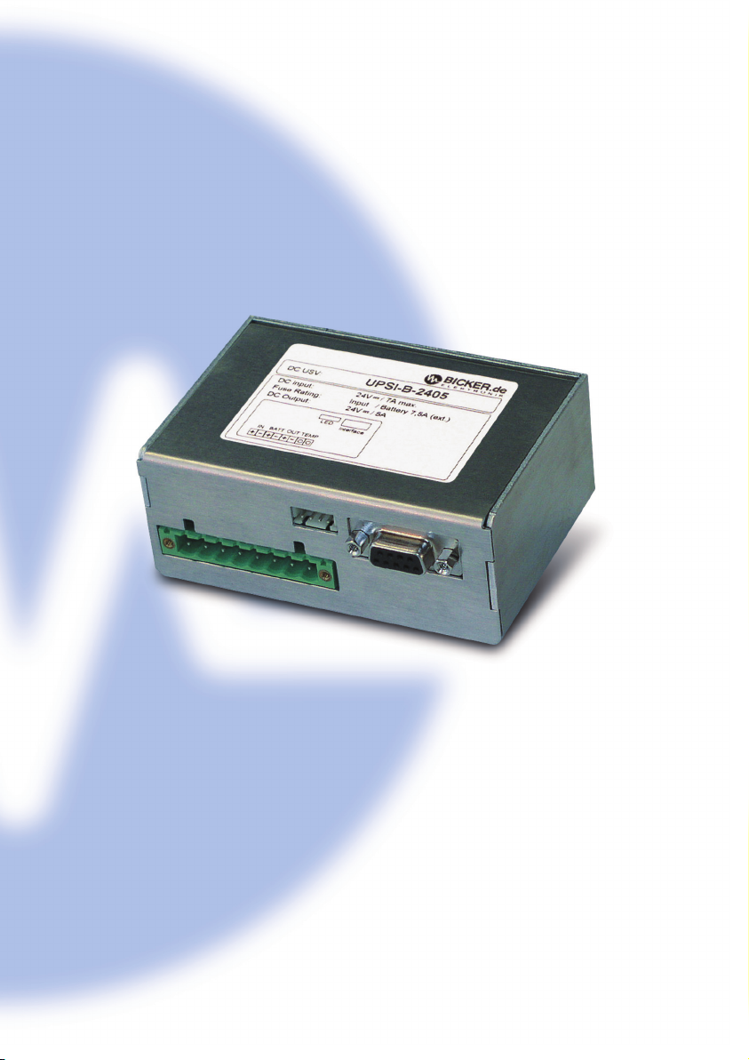
UPSI-B-2405
Industrie-PC-Netzteile
Netzteile
Medizintechnik
DC/DC-Wandler
USV-Systeme
Page 2
Page 3

Benutzerhandbuch UPSI-B-2405
Bicker Elektronik GmbH||Tel.+49 (0)906 70595-0||www.bicker.de
||
info@bicker.de
3
1 Einleitung
2 Prinzipielle Funktion
2.1 Anschlussbild
2.2 Normalbetrieb
2.3 USV-Betrieb
2.4 Anschluss an speisende Quelle
AC/DC-Quelle
DC/DC-Quelle
Mobile DC-Quelle
3 Anzeige
4 Anschlüsse
4.1 DC-Stecker
4.2 DSUB9-Interface
4.3 RUPS2000 OEM (USV-Softwarepaket)
5 Batteriepack
Batterie Kapazitätsberechnung
6 Mechanik
7 Trouble Shooting
8 Sicherheitshinweise
Page 4

Benutzerhandbuch UPSI-B-2405
Bicker Elektronik GmbH||Tel.+49 (0)906 70595-0||www.bicker.de
||
info@bicker.de
4
1 Einleitung
Die Benutzerhinweise begleiten das Datenblatt und gehören zum Lieferumfang eines
jeden DC-USV-Moduls UPSI-B-2405. Allgemeine Informationen, Schutz- und
Warnhinweise sind den Benutzerhinweisen des jeweiligen DC-USV-Moduls bzw. der
vorgeschalteten Quelle zu entnehmen. In den vorliegenden Benutzerhinweisen sind
die Funktionen des DC-USV-Moduls UPSI-B-2405 und die verschiedenen
Anwendungsmöglichkeiten näher beschrieben.
2 Prinzipielle Funktion
Bei einem Ausfall der Netzversorgung versorgt das DC-USV Modul UPSI-B-2405 kritische Verbraucher mit einer DC-Spannung aus dem angeschlossenen Batteriepack.
Über die LED-Anzeige wird der Status optisch angezeigt. Per Schnittstelle können
Signale an einen angeschlossenen PC gemeldet werden.
2.1 Anschlussbild
4
Input
Output
Batterypack
PC System
COM
6 7 8 9
1 2 3 4 5
Interface
Connector 2
1 2 3 4 5 6 7 8
DC-Connector 1
4 3 2 1
LED
F1
F2
UPSI-B-2405
Tem p.
Bild 1
Page 5

Benutzerhandbuch UPSI-B-2405
Bicker Elektronik GmbH||Tel.+49 (0)906 70595-0||www.bicker.de
||
info@bicker.de
55
2.2 Normalbetrieb
Im Normalbetrieb liefert eine vorgeschaltete Spannungsquelle 24 V DC. Diese
Spannung abzüglich 0,4 V DC liegt direkt am Verbraucher (z.B. PC) an. Der angeschlossenen Batteriepack wird von der UPSI-B-2405 geladen.Die LED leuchtet grün und die
Schnittstelle signalisiert „Power ok“.Etwa alle 10 Minuten wird ein Batterietest durchgeführt. Bei defektem Akku oder z.B. nicht angeschlossenem Batteriepack blinkt die
LED rot/grün.
2.3 USV-Betrieb
Sinkt die Versorgungsspannung am Eingang des DC-USV Moduls UPSI-B-2405 unter
die Umschaltspannungsschwelle, übernimmt das UPSI-B-2405 die Versorgung der
angeschlossenen Verbraucher. Die LED leuchtet orange und die Schnittstelle signalisiert „Power Fail“.
Lässt die Kapazität des angeschlossenen Batteriepacks nach (Ausgangsspannung
sinkt auf <21 V), so signalisiert die Schnittstelle „Batterie Low“. Die LED blinkt rot/
orange. Durch einen Impuls auf den „Shutdown“-Eingang kann das DC-USV-Modul
UPSI-B-2405 abgeschaltet werden.
2.4 Anschluss an speisende Quelle
AC
DC
UPSI-B-
2405
PC
Com
Batterie
AC-Quelle:
z.B. AC/DC-Netzteil
DC-Quelle:
z.B. DC/DC-Wandler
DC
DC
Mobile DC-Quelle:
z.B. Batterie
Page 6

Benutzerhandbuch UPSI-B-2405
Bicker Elektronik GmbH||Tel.+49 (0)906 70595-0||www.bicker.de
||
info@bicker.de
6
3 Anzeige
Eine 3-Farben-LED kann an den LED-Stecker 3 (UPSI-B-2405-Gehäuse) angeschlossen
werden.
Belegung: LED-Stecker 3 4321
PIN PIN
1 GND (Bezug) 3 Batterie Low (rot)
2 Power LED (grün) 4 n.c.
LED grün:
Die LED leuchtet grün, solange eine Eingangsspannung (>20 V DC)
vorhanden ist.
LED orange:
Die LED leuchtet orange,sobald das DC-USV-Modul UPSI-B-2405
in den USV-Betrieb schaltet (Eingangsspannung <20 V DC).
LED rot/orange blinkend:
Die LED blinkt im USV-Betrieb rot/orange,wenn die Kapazität des
angeschlossenen Batteriepacks abnimmt (Ausgangsspannung sinkt auf <21 V).
LED rot/grün blinkend:
Die LED blinkt rot/grün, wenn
der angeschlossene Akku tief entladen oder defekt ist.
die Batteriezuleitung oder Sicherung defekt ist.
Die 3-Farben-LED ist im Lieferumfang enthalten.
6
Page 7

Benutzerhandbuch UPSI-B-2405
Bicker Elektronik GmbH||Tel.+49 (0)906 70595-0||www.bicker.de
||
info@bicker.de
77
4 Anschlüsse
4.1 DC-Stecker 1:
Power (PhoenixContact
Bestell-Nr.: FKC 2,5 HC/8-STF-5
)
PIN PIN
1 DC Eingang (+) 22,5…36 V DC 5 DC Ausgang (+) 22,1…35,6 V DC
2 GND 6 GND
3 Batterie (+) BP-2425 Batteriepack 7 Temperatursensor Batterie
4 Batterie (-) BP-2425 Batteriepack 8 Temperatursensor Batterie
Die Ausgangsspannung folgt der Genauigkeit der angeschlossenen Eingangsspannung abzüglich 0,4 VDC. Der Power-Stecker kann einen Leitungsquerschnitt von
2,5 mm
2
aufnehmen und ist im Lieferumfang enthalten.
Hinweis !
Der DC-Eingang (PIN1) und der Batterieanschluss (PIN3) muss jeweils mit einer
7,5 A Sicherung abgesichert werden (F1, F2 – Bild 1 Seite 4).
Der Temperatursensor (NTC 10K an PIN7,8) ist am Batteriepack BP-2425 montiert.
Je nach Temperatur justiert dieser den internen Batterielader des DC-USVModuls UPSI-B-2405.
Weitere Informationen siehe Punkt 5 (Batteriepack).
Page 8

Benutzerhandbuch UPSI-B-2405
Bicker Elektronik GmbH||Tel.+49 (0)906 70595-0||www.bicker.de
||
info@bicker.de
8
4.2 DSUB9-Interface
PIN PIN
1 n.c. 6 Shutdown Eingang
2 Power Fail (Kollektor) Ausgang 7 Bezug Shutdown
3 n.c. 8 n.c.
4 Bezug Power Fail, Batterie Low (Emitter) 9 n.c.
5 Batterie Low (Kollektor) Ausgang
Power Fail
Im Normalbetrieb ist die Kollektor-Emitter-Strecke des Optokopplers nicht „leitend“.
Im USV-Betrieb (Eingangsspannung <20 V DC) ist die Kollektor-Emitter-Strecke des
Optokopplers „leitend“.
Batterie Low
Im Normalbetrieb ist die Kollektor-Emitter-Strecke des Optokopplers nicht „leitend“.
Im USV-Betrieb und schwacher Batteriespannung (<21 V DC) ist die Kollektor-EmitterStrecke des Optokopplers „leitend“.
Shutdown
Bei Anlegen einer Spannung im USV-Betrieb und nach Ablauf von 2 Minuten
Shutdown-Unterdrückung (Punkt 4.3) von +5...24 V DC an PIN6, schaltet das
UPSI-B-2405 nach ca. 5 Sekunden ab.
8
Page 9

Benutzerhandbuch UPSI-B-2405
Bicker Elektronik GmbH||Tel.+49 (0)906 70595-0||www.bicker.de
||
info@bicker.de
9
Für einen digitalen Ausgang (SPS) muss ein „Pull-UP“-Widerstand berechnet werden.
Daten Optokoppler:
Uce 24 VDC
Ice 0,1 Amax
P 0,1 Wmax
UPSI-B-2405
Schnittstelle
(+)
Power Fail
PIN2
Power Fail (Bezug)
PIN4
Page 10

Benutzerhandbuch UPSI-B-2405
Bicker Elektronik GmbH||Tel.+49 (0)906 70595-0||www.bicker.de
||
info@bicker.de
10
4.3 RUPS 2000 OEM (USV-Softwarepaket)
Das USV-Softwarepaket unterstützt die folgenden Windows®-Betriebssysteme:3.1, 95,
98, NT,ME, 2000,XP und 2003 (andere OS auf Anfrage).Die Open Kollektorschnittstelle
des DC-USV-Moduls UPSI-B-2405 ist für die Software RUPS 2000 OEM konzipiert.
Diesem Softwarepaket liegt ein rotes Interfacekabel (M2501) bei, das den Interface
Stecker 2 der UPSI-B-2405 mit einem freien COM Port eines angeschlossenen PC’s
oder Industriecomputer’s verbindet.
Wichtige Grundeinstellungen
Page 11

Benutzerhandbuch UPSI-B-2405
Folgende wichtige Punkte können unter Settings eingestellt werden:
General >> COM Port am PC
E-Mail >> E Mail-Versand über externen E-Mail-Server (nicht im Lieferumfang)
Pager >> Pager-Information über optionales Modem (nicht im Lieferumfang)
Shutdown >> Überbrückungszeit,automatisches Speichern von Dateien,
USV abschalten. Die Überbrückungszeit kann ab Version 3.21 in
0,1-Minutenschritten (6 Sek.) eingestellt werden.
Warnings >> Pop-Up Warnmeldungen
Reboot Funktion
Kehrt während eines Netzausfalls und der schon eingeleiteten Shutdown-Phase von
Windows® das Netz wieder zurück, so „hängt“ das Betriebssystem mit der Meldung:
„Sie können den PC jetzt ausschalten“.Die Reboot- Funktion schaltet das System nach
erfolgtem Shutdown aus und nach ca. 5 Sek. wieder ein.
Shutdown Unterdrückung
Das Shutdown-Signal wird in der Startphase des Systems für ca. 2 Minuten unterdrückt, da eine eventuelle Schnittstellenprüfung von Windows und einem zeitgleichen Netzausfall das Modul sonst abschalten würde. Diese Unterdrückung ist nur
beim ersten Einschalten des Moduls aktiv!
Das RUPS 2000 OEM – USV-Softwarepaket ist nicht im Lieferumfang der UPSI-B-2405
enthalten.
Weitere Informationen im Handbuch auf CD.
Artikel Nr.:RUPS 2000 OEM
USV – Softwarepaket, Bundle Version mit Kabel M2501
Bicker Elektronik GmbH||Tel.+49 (0)906 70595-0||www.bicker.de
||
info@bicker.de
11
Page 12

Benutzerhandbuch UPSI-B-2405
Bicker Elektronik GmbH||Tel.+49 (0)906 70595-0||www.bicker.de
||
info@bicker.de
12
5 Batteriepack
Für Standardanwendungen empfehlen wir unseren Batteriepack BP-2425. Nur mit
diesem Batteriepack kann das DC-USV-Modul UPSI-B-2405 im Temperaturbereich von
–30…+70 °C eingesetzt werden.
Bei Anschluss des Blei-Gel-Batteriepacks BP-2423 ist an PIN7,8 ein 10K 1/4W
Widerstand anzuschließen. Die Ladespannung ist dann fest auf ca. 27,6 V DC
programmiert. Der Temperaturbereich reduziert sich auf 0…+40 °C!
Bei Temperatursensor-Kurzschluss oder -Bruch fällt die Ladeausgangsspannung auf
26,4 V ab.
Der Batteriepack BP2425 ist nicht im Lieferumfang der UPSI-B-2405 enthalten.
Artikel Nr.:BP-2425
CYCLON Batteriepack 24 V / 2,5 Ah. Andere Batteriepacks auf Anfrage.
Batterie Kapazitätsberechnung
Die Batteriekapazität kann mit folgender Formel berechnet werden.
Batterie Kapazität =
Laststrom (A) x Überbrückungszeit (h) x Sicherheitsfaktor (1,5)
Beispiel:
Laststrom 2 A x 0,5 Std.x 1,5 = 1,5 Ah.
Somit könnte der Batteriepack BP-2425 eingesetzt werden.
Page 13

Benutzerhandbuch UPSI-B-2405
6 Mechanik
Bicker Elektronik GmbH||Tel.+49 (0)906 70595-0||www.bicker.de
||
info@bicker.de
13
Zur Befestigung des DC-USV- Moduls in
einem Gehäuse werden M2,5 Schrauben
benötigt.
Das Gewinde der Schraube darf nicht mehr
als 3mm in das Gehäuse hineinragen.
(Kurzschlussgefahr!)
Page 14

7 Trouble Shooting
Kein USV-Betrieb
Leitungsbruch oder Sicherungsdefekt auf der Batterieschiene
Kein Batteriepack angeschlossen
Batteriepack hat nicht genügend Kapazität oder ist entladen
Batteriepack oder Versorgungsspannung verpolt
LED blinkt rot/grün
Leitungsbruch oder Sicherungsdefekt auf der Batterieschiene
Kein Batteriepack angeschlossen
DieUPSI-B-2405 schaltet in Verbindung mit RUPS 2000 OEM nicht ab.
Das Häkchen unter „
Settings
“, „
Shutdown
“ und
„USV abschalten
“
wurde nicht gesetzt.
Die Shutdown-Unterdrückungszeit (Punkt 4.3) wurde nicht abgewartet,und
somit wurde der Shutdown-Impuls „unterdrückt“.
Das Interfacekabel ist defekt oder ein anderes Interfacekabel wurde verwendet.
Batterie wird nicht voll geladen
Temperaturfühler kurzgeschlossen oder unterbrochen
Batteriepack defekt
Keine Funktion
DC Eingangsspannung verpolt?
DC Eingangssicherung defekt?
Kabelquerschnitt zu „klein“?
Der Überspannungsschutz am Eingang (ab 40 V DC) hat angesprochen.
Die interne Supressor-Diode schließt kurz und die Eingangssicherung F1 löst aus.
Dabei geht das UPSI-B-2405 in USV-Betrieb.
Benutzerhandbuch UPSI-B-2405
Bicker Elektronik GmbH||Tel.+49 (0)906 70595-0||www.bicker.de
||
info@bicker.de
14
Page 15

8 Sicherheitshinweise
Im Umgang mit Netzspannung (z. B. vorgeschaltetem AC/DC-Netzteil) sind die
dazugehörigen Sicherheitsvorschriften zu beachten!
Batterien nicht ins Feuer werfen. Verbrauchte Batteriepacks fachgerecht entsorgen.
Bei erhöhter Umgebungstemperatur (>50 °C) und Zyklenbetrieb (ständiges
Laden und Entladen des Akkus), bzw. defektem Akku (LED blinkt rot /grün) kann
der interne Lader überhitzen und ausfallen.
Der DC-Eingang (DC-Stecker 1/ PIN1) und der Batterieanschluss (DCStecker1/ PIN3) muss jeweils mit einer 7,5 A-Sicherung abgesichert werden.
Bei Verpolung am Ausgang kann das UPSI-B-2405 DC-USV-Modul und die angeschlossene Last Schaden nehmen.
Benutzerhandbuch UPSI-B-2405
Bicker Elektronik GmbH||Tel.+49 (0)906 70595-0||www.bicker.de
||
info@bicker.de
15
Page 16

Page 17

User’s Manual UPSI-B-2405
Bicker Elektronik GmbH||Tel.+49 (0)906 70595-0||www.bicker.de
||
info@bicker.de
17
1
Introduction
2 Principle function
2.1 Installation diagram
2.2 Normal mode
2.3 UPS mode
2.4 Connection to source
AC/DC source
DC/DC source
Mobile DC source
3 Display
4 Connection
4.1 DC connector
4.2 DSUB9 interface
4.3 RUPS2000 OEM (UPS monitoring software)
5 Batterypack
Battery capacity calculation
6 Case
7 Trouble Shooting
8 Safety instructions
Page 18

User’s Manual UPSI-B-2405
Bicker Elektronik GmbH||Tel.+49 (0)906 70595-0||www.bicker.de
||
info@bicker.de
18
1 Introduction
The user manual accompanies the data sheet and belongs to the scope of supply of
every DC UPS module UPSI-B-2405. General information, protection and warning
notices can be found in this user manual of the respective DC UPS module and the
connected source.
In this user manual, the function of the DC UPS module UPSI-B-2405 and its various
application possibilities are described in detail. (UPS = uninterruptible power supply)
2 Principle function
In any case of a failure of the main supply the DC UPS module UPSI-B-2405 backs up
critical load with a DC voltage from the connected batterypack. The optional LED
displays the status optically.The interface signalizes to the connected PC.
2.1 Installation diagram
Input
Output
Batterypack
PC System
COM
6 7 8 9
1 2 3 4 5
Interface
Connector 2
1 2 3 4 5 6 7 8
DC-Connector 1
4 3 2 1
LED
F1
F2
UPSI-B-2405
Tem p.
Page 19

User’s Manual UPSI-B-2405
Bicker Elektronik GmbH||Tel.+49 (0)906 70595-0||www.bicker.de
||
info@bicker.de
19
AC
DC
UPSI-B-
2405
PC
Com
Battery
AC source:
e.g.AC/DC supply
DC source:
e.g.DC/DC converter
DC
DC
Mobile DC source:
e.g. battery
2.2 Normal mode
In normal mode the connected power supply provides 24V DC. This voltage, less
0.4 VDC, is directly available at the load (e.g. PC).The connected batterypack will be
charged by the UPSI-B-2405. The optional LED lights green and the interface signals
“power ok“. Every 10 minutes a battery test will be done. If the batterypack isn’t
connected or defective, the LED flashes red/green.
2.3 UPS mode
If the supply voltage at the input of the DC UPS module UPSI-B-2405 drops below the
switching threshold, the DC UPS module UPSI-B-2405 supplies the connected load.
The LED lights orange and the interface signals “power fail“.
If the capacity of the connected batterypack is low (output voltage drops to <21V),
the interface signals “battery low”. The LED flashes red/orange. By an impulse on the
“shutdown“ input the DC UPS module UPSI-B-2405 can be switched off.
2.4 Connection to source
Page 20

User’s Manual UPSI-B-2405
Bicker Elektronik GmbH||Tel.+49 (0)906 70595-0||www.bicker.de
||
info@bicker.de
20
3 Display
A 3-colour-LED can be connected to the LED connector 3 (UPSI-B-2405 case).
Pinning: LED-connector 3 4321
PIN PIN
1 GND (reference) 3 Batterie Low (red)
2 Power LED (green) 4 n.c.
LED
green
:
The LED lights green, as long as input voltage is available (>20 V DC).
LED orange:
The LED lights orange,as soon as the DC UPS module UPSI-B-2405 switches into
the UPS mode (Input voltage <20 V DC).
LED
red/orange flashing
:
In UPS mode the LED flashes red/orange if the capacity of the connected
batterypack is low (Output voltage drops to <21 V).
LED
red/green flashing
:
The LED flashes red/green if
the connected batterypack is empty or defective.
the connection to the battery or fuse is defective.
The 3-colours-LED is included in delivery.
Page 21

User’s Manual UPSI-B-2405
Bicker Elektronik GmbH||Tel.+49 (0)906 70595-0||www.bicker.de
||
info@bicker.de
21
4 Connection
4.1 DC connector 1:
Power (PhoenixContact
Order No.: FKC 2,5 HC/8-STF-5
)
PIN PIN
1 DC input (+) 22.5…36 V DC 5 DC output (+) 22.1…35.6 V DC
2 GND 6 GND
3 Battery (+) BP-2425 batterypack 7 Temperature sensor battery
4 Battery (-) BP-2425 batterypack 8 Temperature sensor battery
The output voltage follows the accuracy of the connected input voltage less 0.4 V DC.
The DC connector 1 can take in a wire size of a line of 2.5 mm
2
and is included in the
scope of supply.
Notice !
A 7.5 A fuse is required at the DC input (PIN1) and at the battery connection
(PIN3) (F1, F2 – see picture 1 page 4). The temperature sensor (NTC 10K at PIN7,8)
is installed at the batterypack BP-2425. Depending on temperature it adjusts the
internal battery charger of the DC UPS module UPSI-B-2405.
Further information see topic 5 (batterypack).
Page 22

User’s Manual UPSI-B-2405
Bicker Elektronik GmbH||Tel.+49 (0)906 70595-0||www.bicker.de
||
info@bicker.de
22
4.2 DSUB9 interface
PIN PIN
1 n.c. 6 Shutdown input
2 Power fail (collector) output 7 Reference shutdown
3 n.c. 8 n.c.
4
Reference power fail,battery low (emitter) 9 n.c.
5
Battery low (collector) output
Power Fail
In normal mode the collector-emitter-distance of the opto coupler isn’t
“conducted“. In UPS mode (input voltage <20 V DC) the collector-emitter-distance
of the opto coupler is “conducted“.
Batterie Low
In normal mode the collector-emitter-distance of the opto coupler isn’t
“conducted“. In UPS mode and in case of low battery voltage (<21 V DC) the
collector-emitter-distance of the opto coupler is ”conducted“.
Shutdown
If connecting a voltage (+5...24 V at PIN6) after 2 minutes shutdown suppression
(topic 4.3) during UPS mode, the UPSI-B-2405 switches off after 5 seconds.
Page 23

User’s Manual UPSI-B-2405
Bicker Elektronik GmbH||Tel.+49 (0)906 70595-0||www.bicker.de
||
info@bicker.de
23
For a digital output (SPS) a “Pull-UP“-resistance has to be calculated.
Data opto coupler:
Uce 24 V DC
Ice 0,1 Amax
P 0,1 Wmax
(+)
UPSI-B-2405
PIN2
Interface
Power Fail (reference)
PIN4
Power Fail
Page 24

User’s Manual UPSI-B-2405
Bicker Elektronik GmbH||Tel.+49 (0)906 70595-0||www.bicker.de
||
info@bicker.de
24
4.3 RUPS 2000 OEM (UPS monitoring software)
The UPS monitoring software supports the following Windows®-operating
systems: 3.1, 95, 98, NT, ME, 2000, XP and 2003 (other OS on request). The open
collector interface of the DC UPS module UPSI-B-2405 is designed for the RUPS
2000 OEM software . This software package includes a red interface cable
(M2501), which connects the interface connector 2 of the UPSI-B-2405 to a free
COM port of a connected PC or Industrial PC.
Important basic adjustments
Page 25

User’s Manual UPSI-B-2405
Bicker Elektronik GmbH||Tel.+49 (0)906 70595-0||www.bicker.de
||
info@bicker.de
25
The following important points can be adjusted at “Settings”
:
General >> COM Port at PC
E-Mail >> Sending E-Mail by an external E-Mail-Server (not in the scope of supply)
Pager >> Pager-Information by an optional modem (not in the scope of supply)
Shutdown >>
Back up time (Shutdown Windows) , auto save application files,
turn off UPS. The back up time can be adjusted in 0,1-minutesteps (6 sec.) starting from version 3.21.
Warnings >> Pop-Up warning
Reboot function
If DC IN fails and main power returns, during shutdown mode of Windows, operating
system will hang with message “Your PC is now save”. After receiving shutdown pulse,
the reboot function will switch off UPS. After about 5 seconds it will switch on.
(User interaction is not necessary)
Shutdown
suppression
The shutdown signal will be disabeled for about 2 minutes while Windows starts up,
because the interface check and a isochronous power fail could switch off UPS
module.
The RUPS 2000 OEM – UPS monitoring software is not contained in the scope of
supply of the UPSI-B-2405.
For further informations please check manual at CD ROM.
Article No.: RUPS 2000 OEM
UPS – monitoring software, Bundle Version with cable M2501
Page 26

User’s Manual UPSI-B-2405
Bicker Elektronik GmbH||Tel.+49 (0)906 70595-0||www.bicker.de
||
info@bicker.de
26
5 Batterypack
For standard application we recommend our batterypack BP-2425. Only this batterypack can be used in the temperature range of -30... +70 °C for UPSI-B-2405.
When connecting lead acid gel batterypack BP-2423 a 10 K 1/4W resistor must be be
connected to PIN7,8. The charging voltage is then fixed on approx. 27.6 V DC. The
temperature range reduces to 0…+40 °C! In case of temperature sensor short-circuit
or open the charger voltage drops to 26.4 V DC.
The batterypack BP-2425 is not contained in the scope of supply of the UPSI-B-2405.
Article Nr.: BP-2425
CYCLON Batterypack 24 V / 2.5 Ah. (Other batterypacks on request)
Battery capacity calculation
Battery capacity can be calculated with the following formula.
Battery capacity=
Load current (A) x Back up time (h) x Safety factor (1,5)
Exemple:
Load current 2 A x 0.5 h x 1.5 = 1.5 Ah.
The batterypack BP-2425 could be used, because it has a capacity of 2.5 Ah.
Page 27

User’s Manual UPSI-B-2405
Bicker Elektronik GmbH||Tel.+49 (0)906 70595-0||www.bicker.de
||
info@bicker.de
27
6 Case
NOTICE!
4 pieces M2,5mm screws are needed to
assemble the UPSI-B-2405 DC UPS module.
The intrusion limit of the screw is 3 mm max.!
Danger of shortage .
press nut
Page 28

User’s Manual UPSI-B-2405
Bicker Elektronik GmbH||Tel.+49 (0)906 70595-0||www.bicker.de
||
info@bicker.de
28
7 Trouble Shooting
No UPS mode
Loose connection or defective fuse on battery rail
No batterypack connected
Batterypack has low capacity or is discharged
Batterypack or supply voltage is reversed
LED flashing red/green
Loose connection or defective fuse on battery rail
No batterypack connected
The DC UPS module UPSI-B-2405 doesn’t switch off in connection with
RUPS 2000 OEM
The checkmark ”Turn off UPS“ at Settings/Shutdown is not set.
The shutdown suppression time (topic 4.3) wasn’t temporized, and thus the
shutdown process was “disabled”.
The interface cable is defective or another interface cable was used.
Battery will not be completely charged
Temperature sensor is short circuited or open
Batterypack is defective
No function
DC input voltage reversed?
DC input fuse defective?
Wire-size to ”small“ and length of supply line to long?
The overvoltage protection at input (starting from 40 V DC) is active.The internal
supressor diode makes a short circuit and the input fuse F1 fails. After this the
UPSI-B-2405 switches to UPS mode.
Page 29

User’s Manual UPSI-B-2405
Bicker Elektronik GmbH||Tel.+49 (0)906 70595-0||www.bicker.de
||
info@bicker.de
29
8 Safety instructions
Only qualified personnel is allowed to work on or arround this equipment.
The successful and safe operation of this equipment is dependent on proper
handling, installation and operation.
The relevant DIN/VDE regulations or equivalent local regulations must be
observed during installation.
Don’t throw battery into fire.Used batterypacks are to be disposed professionally.
Continous charging and discharging at temperatures above 50 °C or defective
battery (LED flashing red/green) may overheat or damage the internal loader.
If there is a reverse polarity at DC output, UPSI-B-2405 and connected load might
be damaged.
Page 30

User’s Manual UPSI-B-2405
Bicker Elektronik GmbH||Tel.+49 (0)906 70595-0||www.bicker.de
||
info@bicker.de
30
Notizen / Notes
Page 31

User’s Manual UPSI-B-2405
Bicker Elektronik GmbH||Tel.+49 (0)906 70595-0||www.bicker.de
||
info@bicker.de
31
Notizen / Notes
Page 32

Industrial PC PSUs
Power supplies
Medical applications
DC/DC converters
UPS systems
2009
th
Bicker Elektronik GmbH
Ludwig-Auer-Straße 23
86609 Donauwörth · Germany
Tel. +49 (0)906 70595-0
Fax +49 (0)906 70595-55
E-Mail: info@bicker.de
Internet: www.bicker.de
Irrtümer und technische Änderungen vorbehalten. Windows® ist ein eingetragenes Warenzeichen der Firma Microsoft Corp. Stand: 04.03.2009 √All data are subject to change without notice. Windows® is a registered trademark of Microsoft Corporation. Status: March 4
 Loading...