

Page 1
Benutzerhandbuch / User’s Manual
UPSI-2401
USV-Systeme
Industrie-PC-Netzteile
Netzteile
Medizintechnik
DC/DC-Wandler
USV-Systeme
Systemkomponenten
Page 2

Benutzerhandbuch UPSI-2401
1 Allgemeines und Hinweise ..................................... 5
1.1 Lieferumfang .................................................................................................... 5
1.2 Optional erhältliches Zubehör .............................................................. 5
2 Technische Daten ..................................................... 6
3 Funktionsprinzip ...................................................... 8
3.1 Netz-Betrieb ...................................................................................................... 8
3.2 Batterie-Betrieb ............................................................................................... 8
4 LED-Anzeige ............................................................... 9
5 Montage und Inbetriebnahme ............................ 10
5.1 DC-Stecker ...................................................................................................... 11
5.2 Schnittstelle 9-polig Sub-D .................................................................. 11
5.3 RUPS2000-B1 (USV-Management-Software) ............................. 12
5.4 Besonderes Verhalten der UPSI-2401 ............................................ 13
6 Fehlerbehebung ................................................... 14
2
3
Page 3
Benutzerhandbuch UPSI-2401
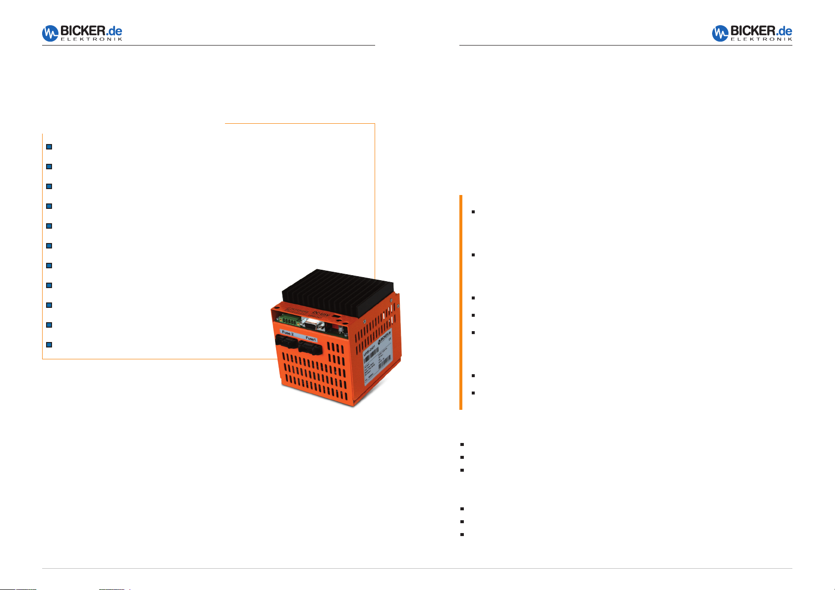
Ihre Vorteile auf einen Blick
Kontinuierliche Überwachung der Batteriekapazität
Temperaturgeführte und schonende Batterie-Ladung
Abschaltung auch bequem über Timerfunktion möglich
Shutdown-Unterdrückung während der Startphase
USV-Management-Software optional erhältlich
Überlast- und Kurzschluss-Schutz am Ausgang
Automatischer Neustart durch Reboot-Funktion
Lastsensor verhindert ungewollte Entladung
Batterielader vor Übertemperatur geschützt
PC-Schnittstelle on Board
„
Batterie defekt“-Anzeige
Benutzerhandbuch UPSI-2401
1 Allgemeines und Hinweise
Herzlichen Glückwunsch zu Ihrer neuen UPSI-2401!
Dieses Handbuch soll Sie mit den Komponenten und Eigenschaften der DC-USV
UPSI-2401 vertraut machen. Wir haben alle Sorgfalt walten lassen, um in diesem
Handbuch vollständige und genaue Informationen über unser Produkt zu liefern. Für
möglicherweise vorhandene Fehler kann jedoch keine Haftung übernommen werden.
Hinweise auf vorhandene Fehler, Verbesserungsvorschläge und Kritik nehmen wir dankbar entgegen.
Hi n we is e
Die Installation und Inbetriebnahme darf nur von entsprechend qualifiziertem
Fachpersonal durchgeführt werden.
Dabei sind die jeweiligen Vorschriften einzuhalten!
Alle Anschluss-Leitungen müssen entsprechend dem Eingangsstrom der UPSI-2401
(5,5 A) dimensioniert und abgesichert werden.
Der empfohlene Querschnitt für die Anschluss-Leitungen ist 1 mm
Bei Verpolung kann die USV und die angeschlossene Last Schaden nehmen.
Auf ausreichende Konvektion ist zu achten!
Die Lebensdauer der Batterien beträgt bei +20 °C 4…5 Jahre und halbiert sich
um je 10 °C Temperaturerhöhung nach EUROBAT! Die Gebrauchsdauer ist auch
abhängig von der Temperatur, der Entladetiefe und der Anzahl der Ladezyklen.
Bei Einlagerung soll die USV spätestens nach 6 Monaten nachgeladen werden.
Um den Eigenverbrauch bei Lagerung zu minimieren, sollen die Sicherungen
gezogen werden.
2
.
1.1 Lieferumfang
DC-USV UPSI-2401 mit eingebauten 12 V / 1,2 Ah Batterien
Anschluss-Steckverbinder, Phoenix Contact, 5-polig
2 Sicherungen 7,5 A
1.2 Optional erhältliches Zubehör
RUPS 2000-B1, USV-Management-Software
CB-RS-020, Schnittstellenkabel, 2 m
F1-0162 Montageplatte für UPSI-2401
4
5
Page 4

Benutzerhandbuch UPSI-2401
100,0 mm
Benutzerhandbuch UPSI-2401
2 Technische Daten der DC-USV UPSI-2401
Te ch ni s ch e Da t e n
Eingangsspannung 24 V DC (22,5…30 V)
Eingangsstrom 5,5 A max.
Ausgangsspannung Im Normalbetr.: ca. 0,5 V unterhalb Eingangsspannung
Im Batteriebetr.: ca. 29…19 V DC
Ausgangsstrom 5 A max.
Batterieladestrom 0,4 A max. (interner Batterielader)
Ladeverfahren UI-Kennlinie, temperaturgeführt
Schutzfunktionen Tiefentlade-Schutz: 19 V DC ±2 %
Überlast-Schutz am Ausgang: 10 A für 2 Sek., Abschalt.
Kurzschluss-Schutz: Abschaltung
Umschaltschwellen Netz/Batterie 20 V DC ±2 %, Batterie/Netz 22 V DC ±2 %
Schnittstelle DSUB9-Buchse
Ausgänge: Power Fail, Battery Low Eingang: Shutdown
Optional auch mit USV-Software zur Anbindung an
gängige Betriebssysteme lieferbar
Batterietyp Eingebaute Blei-Gel-Batterie, wartungsfrei, 1,3 Ah
Sicherheit / EMV CE
Temperatur Betrieb: 0…+40 °C / Lagerung: -10…+40 °C
Luftfeuchtigkeit Betrieb: 10…85 % RH, nicht kondensierend
Lagerung: 10…90 % RH, nicht kondensierend
Abmessungen 105 x 129 x 122 ±0,5 mm
Gewicht (netto) 2 kg
Zeichnung UPSI-2401
114 mm
122 mm
Montageplatte
F1-0162,
optionales Zubehör
80,0 mm
t = 2,5 mm
130,0 mm
150,0 mm
Pr od uk t sp e zi f is c he An ga be n
LED-Anzeige 3-Farben-LED für „Power ok” (grün), „Power Fail” (orange), „Battery low”
(rot/orange blinkend) und „Batterie defekt” (rot/grün blinkend);
Kurzschluss am Ausgang/Überlast (rot); Weitere Angaben Seite 9
Batterieüberwachung Batterietest erfolgt im Normalbetrieb ca. alle 10 Minuten, bei Meldung
„Batterie defekt“ blinkt die LED rot/grün (optional Meldekontakt)
Eigenverbrauch Ca. 50 mA
Shutdown- Das Shutdown-Signal wird in der Startphase des Systems für ca. 2 Minuten
Unterdrückung unterdrückt.
Reboot-Funktion Kehrt während eines Netzausfalls und der schon eingeleiteten Shutdown-
Phase von Windows® die Netzspannung wieder zurück, so „hängt” das
Betriebssystem mit der Meldung „Sie können den PC jetzt ausschalten“. Die
Reboot-Funktion hingegen schaltet das System nach erfolgtem Shutdown
aus und nach ca. 10 Sek. wieder ein.
Lastsensor Abschaltung im USV-Betrieb <10 Watt
Timerfunktion 2 Min – 6 Min – 20 Min – aus, einstellbar über DIP-Schalter
Überbrückungszeit Ca. 30 Min bei 1 A /ca. 8 Min bei 3 A /ca. 3 Min bei 5 A (gem. bei +20 °C)
6
111 mm
129 mm
105 mm
7,5 mm
Sicherungen
Toleranz ±0,5 mm
7
Page 5
Benutzerhandbuch UPSI-2401
Benutzerhandbuch UPSI-2401
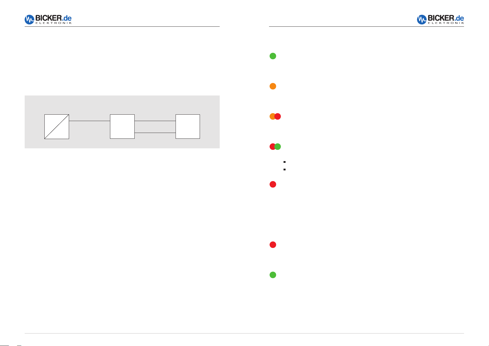
3 Funktionsprinzip
Bei einem Ausfall der Netzversorgung versorgt die DC-USV UPSI-2401 den angeschlossenen Verbraucher mit einer DC-Spannung aus dem internen Batteriepack. Über die
LED-Anzeige wird der Status optisch angezeigt. Per Schnittstelle können Signale an einen
angeschlossenen PC gemeldet werden.
Quelle:
3.1 Netz-Betrieb
Im Netz-Betrieb liefert eine vorgeschaltete Spannungsquelle 24 VDC. Diese Spannung
abzüglich ca. 0,45 V DC liegt direkt am Verbraucher (z. B. PC) an. Der interne Batteriepack
wird von der UPSI-2401 geladen. Die LED leuchtet grün und die Schnittstelle signalisiert „Power ok“. Etwa alle 10 Minuten wird ein Batterietest durchgeführt. Bei defektem
Batteriepack oder Leitungsbruch blinkt die LED rot/grün.
z. B. AC/DC-Netzteil
AC
DC
DC-USV
UPSI-2401
Verbraucher
(PC)
Schnittstelle
4 LED-Anzeige
Power ok
Die LED leuchtet grün, solange eine Eingangsspannung (>20 V DC)
vorhanden ist.
Power fail (Netzausfall)
Die LED leuchtet orange, sobald die DC-USV UPSI-2401
in den Batterie-Betrieb schaltet (Eingangsspannung <20 V DC).
Battery low (Batterie schwach)
Die LED blinkt im Batterie-Betrieb rot/orange, wenn die Kapazität des
internen Batteriepacks abnimmt (Batteriespannung sinkt auf <21 V).
Battery fail (Batterie defekt)
Die LED blinkt rot/grün, wenn
USV kann durch Netztrennung wieder neu gestartet werden.
der interne Batteriepack tief entladen oder defekt ist.
die Batteriezuleitung oder Sicherung defekt ist.
Kurzschluss am Ausgang
Kurzschluss bzw. Überlast am Ausgang beseitigen.
3.2 Batterie-Betrieb
Sinkt die Versorgungsspannung am Eingang der DC-USV UPSI-2401 unter die Umschaltspannungsschwelle, übernimmt die UPSI-2401 die Versorgung der angeschlossenen
Verbraucher. Die LED leuchtet orange und die Schnittstelle signalisiert „Power Fail“. Lässt
die Kapazität des internen Batteriepacks nach (Batteriespannung sinkt auf <21 V), so
signalisiert die Schnittstelle „Batterie Low“. Die LED blinkt rot/orange. Durch einen Impuls
auf den „Shutdown“-Eingang kann die DC-USV UPSI-2401 abgeschaltet werden.
8
LED-Anzeigen bei Umschaltung in den USV-Betrieb und Absenkung der
Eingangsspannung auf 20 V…17 V
Rot blinkend
Die LED blinkt rot, wenn die USV wegen einer defekten Batterie, Batteriesicherung
oder nicht angeschlossener Batterie abschaltet.
Grün blinkend
Die LED blinkt grün, wenn die USV nach Erhalt des Shutdown-Signals (DSuB)
bzw. nach Aktivierung des Lastsensors (<10 W) nach ca. 10…15 Sek abschaltet.
9
Page 6

Benutzerhandbuch UPSI-2401
Benutzerhandbuch UPSI-2401
5 Montage und Inbetriebnahme
Anschlussbild
DIP
LED
IN +
GND
DC-Stecker 1
IN IN
1 3 52 4
OUTOUT
D-SUB
DC-Stecker
1 Erde
2 Eingang (+)
3 Eingang (–)
4 Ausgang (–)
5 Ausgang (+)
OUT +
GND
Timerfunktion
off
Timer
off
1 O
2
PC System
Interface Stecker 2: DSUB9
Interface für RUPS2000
1 Battery low Ausgang
2 n.c.
3 n.c.
4 Shutdown Eingang
5 Ground
6 n.c.
7 n.c.
8 Power Fail Ausgang
9 n.c.
2 min. 6 min. 20 min.
offS1S2off on
offonon on
DIP
N
COM
5.1 DC-Stecker: Anschluss Ein- und Ausgang
Typ:
FRONT-MC1,5/5-STF-3,81
PIN
1 Erde
2 Eingang (+)
3 Eingang (–)
4 Ausgang (–)
5 Ausgang (+)
Die Ausgangsspannung folgt der angeschlossenen Eingangs spannung abzüglich ca. 0,45 V DC.
Der Anschluss-Steck ver binder (5-polig) ist im
Lieferumfang der DC-USV UPSI-2401 enthalten.
5.2 Schnittstelle 9-polig Sub-D
PIN
1 Battery low Ausgang
2 n.c.
3 n.c.
4 Shutdown Eingang
5 Ground
6 n.c.
7 n.c.
8 Power Fail Ausgang
9 n.c.
IN
IN–OUT–OUT
+
+
Power Fail (Ausgang)
Hi n we is e
Die Einbaulage der DC-USV UPSI-2401 ist waagrecht.
Es ist sicherzustellen, dass im Betrieb eine ausreichende Konvektion erfolgt.
Alle Anschluss-Leitungen müssen entsprechend dem Eingangsstrom der UPSI-2401
(5,5 A) dimensioniert und abgesichert werden. Der empfohlene Querschnitt für die
Anschluss-Leitungen ist 1 mm
Vor dem Einschalten ist die ordnungsgemäße Verkabelung sicherzustellen. Beide
2
.
Batterie-Sicherungen (7,5 A) müssen gesteckt sein.
Fällt die Netzspannung aus (unter 20 V DC), sinkt der Pegel auf -7 V DC.
Ist die Netzspannung ok, liegt der Pegel bei +7 V DC.
Batterie Low (Ausgang)
Ist die Batterie schwach, fällt der Pegel auf -7 V DC.
Ist die Batterie ok, liegt der Pegel bei +7 V DC.
Shutdown (Eingang)
Signal, um den PC im USV-Betrieb abzuschalten.
Der Pegel muss ≥+7 V DC sein und ≥60 msec. anliegen. Die USV schaltet dann nach ca.
15 Sek. ab.
10
11
Page 7

Benutzerhandbuch UPSI-2401
Timerfunktion
Benutzerhandbuch UPSI-2401
5.3 RUPS 2000-B1 (USV-Management-Software)
Das USV-Softwarepaket unterstützt die folgenden Windows®-Betriebssysteme: 2000,
2003, XP, Vista 7 und 8 (andere OS auf Anfrage). Die Open Kollektorschnittstelle des
DC-USV-Moduls UPSI-2401 ist für die Software RUPS 2000-B1 konzipiert. Diesem
Softwarepaket liegt optional das CB-RS-020 Schnittstellen-Kabel bei. Damit kann die
UPSI-2401 mit einem freien COM-Port eines angeschlossenen PC’s verbunden werden.
Wichtige Grundeinstellungen
5.4 Besondere Vorteile der UPSI-2401
Reboot-Funktion
Kehrt während eines Netzausfalls und der schon eingeleiteten Shutdown-Phase von
Windows® das Netz wieder zurück, so „hängt“ das Betriebssystem mit der Meldung:
„Sie können den PC jetzt ausschalten“. Die Reboot- Funktion schaltet das System nach
erfolgtem Shutdown aus und nach ca. 5 Sek. wieder ein.
Es ist kein Bedienereingriff notwendig.
Shutdown Unterdrückung
Das Shutdown-Signal wird in der Startphase des Systems für ca. 2 Minuten unterdrückt, da eine eventuelle Schnittstellenprüfung von Windows und einem zeitgleichen
Netzausfall das Modul sonst abschalten würde. Diese Unterdrückung ist nur beim ersten
Einschalten des Moduls aktiv!
Lastsensor
Der integrierte Lastsensor schaltet die UPSI-2401 im USV-Betrieb <10 W ab. Somit können
auch PCs ohne ACPI (Advanced Configuration and Power Interface) sicher abgeschaltet
werden.
Fällt bei ausgeschaltetem PC die Eingangsspannung aus, schaltet sich die USV über den
Lastsensor selbstständig ab. Die eingebaute Batterie wird somit nicht entladen.
Timerfunktion
Wenn keine USV-Management-Software verwendet wird, kann die USV auch zeitgesteuert abgeschaltet werden
USV abschalten. Die Überbrückungszeit kann ab Version 3.21 in
0,1-Minutenschritten (6 Sek.) eingestellt werden.
12
General >> COM Port am PC
E-Mail >> E Mail-Versand über externen E-Mail-Server (nicht im Lieferumfang)
Pager >> Pager-Information über optionales Modem (nicht im Lieferumfang)
Shutdown >> Überbrückungszeit, automatisches Speichern von Dateien,
Warnings >> Pop-Up Warnmeldungen
Timer
off
2 min. 6 min. 20 min.
off
offonon on
DIP
1 O
2
offS1S2off on
N
13
Page 8

Benutzerhandbuch UPSI-2401
6 Fehlerbehebung
PC „stürzt“ im USV-Betrieb ab
Leitungsbruch oder Sicherungsdefekt auf der Batterieseite
Angeschlossene Last <10 W (Lastsensor)
Batteriepack hat nicht genügend Kapazität oder ist entladen
Battery fail (Batterie defekt)
Die LED blinkt rot/grün, wenn
Weitere Anzeige-Schemen siehe Seite 9.
Die UPSI-2401 schaltet in Verbindung mit RUPS 2000-B1 nicht ab.
wurde nicht gesetzt.
somit wurde der Shutdown-Impuls „unterdrückt“.
verwendet.
Batterie wird nicht voll geladen
Keine Funktion
Kontaktieren Sie unseren Service!
Die interne Supressor-Diode schließt kurz und die interne Eingangssicherung löst
aus. Dabei geht die UPSI-2401 in Batterie-Betrieb. >> Kontaktieren Sie unseren Service!
der interne Batteriepack tief entladen oder defekt ist.
die Batteriezuleitung oder Sicherung defekt ist.
Das Häkchen unter „Settings“, „Shutdown“ und „USV abschalten“
Die Shutdown-Unterdrückungszeit (Punkt 5.4) wurde nicht abgewartet, und
Das Schnittstellenkabel ist defekt oder ein falsches Schnittstellenkabel wurde
Batteriepack defekt
Eingangsspannung verpolt? >> Interne Eingangssicherung defekt.
Vorgeschaltete Eingangssicherung defekt? >> Eingangssicherung erneuern
Der Überspannungsschutz am Eingang (ab 32 V DC) hat angesprochen.
User’s Manual UPSI-2401
1 General Information and Safety Warnings ....... 17
1.1 Contents of Delivery ................................................................................. 17
1.2 Optional Accessories ................................................................................ 17
2 Technical Data......................................................... 18
3 Functional Description .......................................... 20
3.1 Mains Mode ................................................................................................... 20
3.2 Battery Mode ................................................................................................. 20
4 LED Display ...............................................................21
5 Installation and Start up ....................................... 22
5.1 DC Connector ............................................................................................... 23
5.2 Interface 9-pole Sub-D ............................................................................ 23
5.3 RUPS2000-B1 (UPS Management Software) ............................. 24
5.4 Special Features of the UPSI-2401 ................................................... 25
6 Troubleshooting ................................................... 26
English
14
15
Page 9

Your advantages at a glance
Continuous monitoring of battery capacitance
Temperature-regulated and gentle charging of battery
Comfortable switch-off via timer function also possible
Shutdown suppression during start-up
English
UPS Management Software optionally available
Output with overload and short-circuit protections
Battery cahrger protected against overtemperature
Load sensor prevents undesirable discharge
Reboot function for automatic restart
PC interface on board
„
Battery defect“ display
User’s Manual UPSI-2401
User’s Manual UPSI-2401
1 General Information and Safety Warnings
Congratulations for choosing the UPSI-2401!
This manual explains the components and properties of the DC UPS UPSI-2401. All information contained in this manual has been revised thoroughly to ensure accuracy and
completeness. Yet Bicker Electronic accepts no liability for any omissions or faults. We will
appreciate any notifications regarding faults, suggestions for improvements and criticism.
Sa f et y Wa rn in g s
Installation and connection must only be carried out by qualified personnel.
The relevant rules of electrical engineering must be observed!
All connector cables must be dimensioned for the input current of the
UPSI-2401 (5.5 A) and an according additional protection must be provided and
fused. The recommended cross section for the connector cables is 1 mm
A polarity reversal can damage the UPS as well as the connected load.
Make sure sufficient convection is possible!
The service life of the batteries is app. 4…5 years at +20 °C and will decrease by half
with each temperature increase of 10 °C according to EUROBAT! The service life
depends also on temperature, discharge depth an the numbers of loading cycles.
During storage the UPS has to be charged at least every 6 months.
To minimize the power consumption during storage, the fuses
should be removed.
2
.
English
1.1 Contents of Delivery
DC UPS UPSI-2401 with equipped 12 V / 1.2 A batteries
Pin-and-socket connector, Phoenix contact, 5-pole
2 fuses 7.5 A
1.2 Optional Accessories
RUPS 2000-B1, UPS Management Software
CB-RS-020, interface cable, 2 m
F1-0162 Mounting plate for UPSI-2401
16
17
Page 10

User’s Manual UPSI-2401
100,0 mm
User’s Manual UPSI-2401
2 Technical Data of the DC-UPS UPSI-2401
Te ch ni c al d at a
Input voltage 24 V DC (22.5…30 V)
Input current 5.5 A max.
Output voltage In normal mode: app. 0.5 V below input voltage
In battery mode: app. 29…19 V DC
Output current 5 A max.
Battery charge current 0.4 A max. (internal battery charger)
Charging method UI characteristic, with temperature regulation
Protection Deep discharge protection: 19 V DC ±2 %
Overload protection at output: 10 A for 2 sec, switch off
Short-circuit protection: Switch off
Transfer time / limits Mains/battery 20 V DC ±2 %, Battery/mains 22 V DC ±2 %
Interface DSUB9 connector, female
English
Outputs: Power Fail, Battery Low Input: Shutdown
Optionally also available with UPS software for
connection to common operating systems
Type of battery Equipped lead-gel-battery, maintenance-free, 1.3 Ah
Safety / EMC CE
Temperature Operating: 0…+40 °C / Storage: -10…+40 °C
Humidity Operating: 10…85 % RH, non-condensing
Storage: 10…90 % RH, non-condensing
Dimensions 105 x 129 x 122 ±0.5 mm
Weight (net) 2 kg
Drawing UPSI-2401
114 mm
122 mm
Mounting plate
F1-0162,
optional accessory
80,0 mm
t = 2,5 mm
130,0 mm
150,0 mm
English
Pr od uc t s pe ci fi c d at a
LED display 3-colour-LED for „Power ok” (green), „Power Fail” (orange), „Battery low”
(red/orange flashing) and „Battery defect” (red/green flashing), short circuit at
output/overload (red)
Battery monitoring Battery test is carried out in normal mode approx every 10 minutes,
in case of “Battery defect“ notification the LED flashes red/green
(optional signaling contact)
Power consumption App. 50 mA
Shutdown suppression During system start-up the shutdown signal is suppressed for app. 2 minutes
Reboot function If power fails and then returns during the shutdown mode of Windows®,
the operating system will ‚lock‘ with the message „Your PC is now safe“.
The reboot function restarts the system after about 10 seconds.
Load sensor Switch-off in UPS mode <10 Watt
Timer function 2 min – 6 min – 20 min, adjustable via DIP switch
Back up time App. 30 min at 1 A /app. 8 min at 3 A /app. 3 min at 5 A, (meas. at +20 °C)
18
111 mm
129 mm
105 mm
7,5 mm
Fuse
Tolerance ±0.5 mm
19
Page 11

User’s Manual UPSI-2401
User’s Manual UPSI-2401
3 Functional Description
In case of a mains voltage failure the DC UPS UPSI-2401 supplies the connected
consumer load with DC voltage from the internal battery pack. Via LED display the status
is visualised. Signals can be informed to a connected PC via interface.
Source:
e. g. AC/DC power supply
AC
DC
DC UPS
UPSI-2401
Consumer
load (PC)
Interface
English
3.1 Mains Mode
In mains mode a voltage source at the input line supplies 24 VDC. This voltage minus
app. 0.45 VDC is provided directly at the consumer load (e. g. PC). The internal battery pack is charged by the UPSI-2401. The LED is green and the interface signalises
“Power ok“. App. every 10 minutes a battery test is carried out. In case of a defect
battery pack or a cable brake, the LED flashes red/green.
4 LED Display
Power ok
The LED is green as long as an input voltage (>20 V DC) is present.
Power fail (mains power failure)
The LED turns to orange as soon as the DC UPS UPSI-2401 switches
to battery mode (input voltage <20 V DC).
Battery low
The LED flashes red/orange in battery mode when the capacitance of the
internal battery pack decreases (battery voltage dropping to <21 V).
Battery fail (Battery defect)
The LED flashes red/green
UPS can be re-started by disconnecting from the mains.
when the internal battery pack is discharged or defect.
when the battery supply line or fuse is defect.
Short circuit at output
Remove short-circuit or overload at the output.
English
3.2 Battery Mode
If the supply voltage drops below the switch-over threshold at the input of the
DC UPS, the UPSI-2401 takes over supplying the connected consumer loads.
The LED is orange and the interface signalises “Power Fail“. When the capacitance of the internal battery pack decreases (battery voltage dropping to
<21 V), the interface signalises “Battery Low“. The LED flashes red/orange. The DC UPS
UPSI-2401 can be switched off by an impulse at the “Shutdown“ input.
20
LED Display at switch to UPS mode and reduction of input voltage to 20 V…17 V
Red flashing
The LED is flashing red when the UPS switches off in case of a defect battery, fuse
or not connected battery.
Green flashing
The LED is flashing green when the UPS switches off approx. 10 to 15 seconds after
receipt of the shutdown signal (DSuB) and activation of the power sensor (<10 W)
resp.
21
Page 12

User’s Manual UPSI-2401
User’s Manual UPSI-2401
5 Installation and Start up
Connections
English
DC connector 1
IN IN
IN +
GND
1 3 52 4
OUTOUT
D-SUB
5.1 DC Connector: Input and output connection
DC connector 1
1 Earth
2 Input (+)
3 Input (–)
4 Output (–)
5 Output (+)
Timer function
Timer
off
2 min. 6 min. 20 min.
off
offonon on
DIP
1 O
2
Interface connector 2:
DSUB9 Interface für
RUPS2000
1 Battery low output
2 n.c.
3 n.c.
4 Shutdown input
5 Earth
6 n.c.
7 n.c.
8 Power Fail output
9 n.c.
offS1S2off on
N
Type:
PIN
1 Earth
2 Input (+)
3 Input (–)
4 Output (–)
5 Output (+)
5.2 Interface 9-pole Sub-D
PIN
1 Battery low output
2 n.c.
3 n.c.
FRONT-MC1,5/5-STF-3,81
The output voltage corresponds to the connected input
voltage minus app. 0.45 V DC.
The (5-pole) pin-and-socket connector is included in the
delivery of the DC UPS UPSI-2401.
IN
IN–OUT–OUT
+
+
English
4 Shutdown input
5 Ground
6 n.c.
7 n.c.
DIP
LED
OUT +
GND
PC System
COM
8 Power Fail output
9 n.c.
Power Fail (Output)
If AC input fails (below 20 V DC), level decreases to -7 V DC.
If AC input ok, level is at +7 V DC.
No t es
The DC UPS UPSI-2401 must be mounted horizontally.
Ensure there is sufficient convection during operation.
All connector cables must be dimensioned for the input current of the
UPSI-2401 (5.5 A) and an according additional protection must be provided and
fused. The recommended cross section for the connector cables is 1 mm
Before switching on the unit, make sure all connections are correct.
2
.
Both fuses (7.5 A) must be engaged.
22
Battery Low (Output)
If the battery is low, level decreases to -7 V DC.
If the battery is ok, level is at +7 V DC.
Shutdown (Input)
Signal to switch off the PSU in UPS mode.
The level has to be ≥+7 V DC and has to be connected ≥60 msec. The UPS switches off
after app. 15 sec.
23
Page 13

User’s Manual UPSI-2401
Timer function
User’s Manual UPSI-2401
5.3 RUPS 2000-B1 (UPS Management Software)
The UPS software package supports the following operating systems of Windows®:
2000, 2003, XP, Vista, 7 and 8 (other OS upon request). The open collector interface of the DC UPS UPSI-2401 has been designed for the software RUPS 2000-B1.
Optionally the interface cable CB-RS-020 is included into the delivery of this software
package. With this cable the UPSI-2401 can be connected to a free COM-Port of a
connected PC.
Important basic settings
English
5.4 Special Features of the UPSI-2401
Reboot Function
If DC IN fails and main power returns during shutdown mode of Windows®, the operating
system will ‘lock’ with the message “Your PC is now safe”. The reboot function restarts the
system after about 5 seconds.
No intervention of the user is required.
Shutdown Suppression
The shutdown signal is suppressed for about 2 minutes while the system is starting
up, since a possible interface check of Windows® with a simultaneous power failure
would switch the UPSI-2401 off. This suppression is only active when the module is
switched on for the first time.
Load sensor
The integrated load sensor switches the UPSI-2401 off >10 W in UPS mode.
Thus, also PCs without ACPI (Advanced Configuration and Power Interface) can be
switched off safely. If input voltage fails while PC is switched off, the UPS switches itself off
via the load sensor. Thus, the equipped battery is not discharged.
Timer function
In case no UPS Management Software is used the timer function can be used to switch
off the UPSI-2401 in UPS mode after a pre-adjusted interval.
off
Timer
2 min. 6 min. 20 min.
off
offonon on
DIP
1 O
2
offS1S2off on
N
English
General >> COM Port at PC
E-Mail >> Sending e-mails via external e-mail server (not included in delivery)
Pager >> Pager information on optional modem (not included in delivery)
Shutdown >> Back-up period, automatic storage of files, switch off UPS.
From version 3.21 the back-up period can be set in steps of
0.1 minutes (6 sec.).
Warnings >> Pop-Up warning messages
24
25
Page 14

User’s Manual UPSI-2401
User’s Manual UPSI-2401
6 Troubleshooting
PC System crash during UPS mode
Connection interrupted or defect fuse on battery side
Connected load <10 W (load sensor)
Battery pack has not enough capacitance or is discharged
Battery fail (Battery defect)
The LED flashes red/green
For further display schemes please have look at page 21.
English
The UPSI-2401 does not switch off in connection with RUPS 2000-B1.
abschalten) was not set.
impulse was, thus, “suppressed“.
Battery is not fully charged
when the internal battery pack is discharged or defect.
when the battery supply line or fuse is defect.
The checkmark under “Settings“, “Shutdown“ and “Switch off UPS“ (USV
The shutdown suppression period (see 5.4) was disturbed, and the shutdown
The interface cable is defect or a wrong interface cable was used.
Battery pack defect
Notizen / Notes
English
No function
Polarity reversal of input voltage? >> internal fuse defect
Please contact our service!
Upstream input fuse defect? >> replace input fuse
The overvoltage protection at the input (from 32 V DC) was activated.
Short circuit of internal suppressor diode blows input fuse and the UPSI-2401
switches to battery mode. >> Please contact our service!
26
27
Page 15

Industrial PC PSUs
Power supplies
Medical applications
DC/DC converters
UPS systems
System components
Irrtümer und technische Änderungen vorbehalten.
Windows® ist ein eingetragenes Warenzeichen der Firma Microsoft Corp.
Subject to errors and technical modifications.
Windows® is a registered trademark of Microsoft Corporation.
Stand/Issued: 03.06.2014
Bicker Elektronik GmbH
Ludwig-Auer Straße 23
86609 Donauwörth · Germany
Tel. +49 (0)906 70595-0
Fax +49 (0)906 70595-55
E-Mail: info@bicker.de
www.bicker.de
 Loading...