

Bicker Elektronik UPSI-2406IP-24U, UPSI-IP-2, UPSI-2406IP-24UW, UPSI-2406IP-12U, UPSI-2406IP-26 User Manual
...Page 1
Benutzerhandbuch
UPSI-IP-1 series
Deutsch English
User Manual
UPSI-IP-2 series
Page 2

Deutsch
UPSI-IP-1-Serie | UPSI- IP-2-Serie
UPSI-IP-1
UPSI-IP-2
2
Page 3

UPSI-IP-1-Serie | UPSI- IP-2-Serie
1 Produkt- und Funktionsbeschreibung ...........................................4
2 Vor Inbetriebnahme lesen ................................................................4
3 Bestimmungsgemäße Verwendung – Beschreibung ..................5
4 Einbau – Installationshinweise .........................................................7
5 Konvektion und Einbaulage .............................................................7
6 Anschlussbeschreibung ....................................................................8
7 Dimensionierung der vorgeschalteten Stromversorgung ...... 10
8 Inbetriebnahme ............................................................................... 13
9 Anschlussplan ................................................................................... 14
10 Sicherheitsmaßnahmen ................................................................. 15
11 Ladezeit .............................................................................................. 15
12 Verpolung / Überlast / Kurzschluss / Übertemperatur ............. 16
13 Überbrückungszeiten ..................................................................... 16
14 Verhalten bei Überschreiten der maximalen Pufferzeiten ...... 16
15 Status LED.......................................................................................... 17
16 Empfehlungen für eine lange Lebensdauer des USV-Systems 18
17 Wartung ............................................................................................. 18
18 Entsorgung ........................................................................................ 18
19 Haftungsausschluss ......................................................................... 18
20 Software ............................................................................................. 19
21 Befehlsliste ........................................................................................ 23
Deutsch
3
Page 4
UPSI-IP-1-Serie | UPSI- IP-2-Serie
Herzlichen Glückwunsch zu Ihrem neuen Qualitätsprodukt!
Dieses Handbuch soll den Anwender mit dem Produkt samt dessen Komponenten und
Eigenschaften vertraut machen und möglichst vollständige und genaue Informationen
dazu liefern. Für mögliche vorhandene Fehler kann Bicker Elektronik jedoch keine Haftung
übernehmen. Hinweise hierzu, Verbesserungsvorschläge und Kritik werden jederzeit sehr
gerne entgegengenommen.
1 Produkt- und Funktionsbeschreibung
UPSI-IP-1- und UPSI-IP-2-Serie
Deutsch
Bei den Geräten der UPSI-IP-1- und -2 Serie (nachfolgend auch USV(s)) handelt es sich
um kombinierte
Speichermedium inklusive. Sie verfügen über zahlreiche digitale Features und einer
hohen Performance und wurden für den Außeneinsatz bzw. Einsatz unter extremeren
Bedingungen entwickelt. Sie basieren auf den Technologien der UPSI-1208/-2406. Bei
den unterschiedlichen Speichermedien (nachfolgend auch Batteriepack, Akku etc.)
handelt es sich entweder um Supercap- oder LiFePO4-Packs. Zudem verfügen einige
Versionen der UPSI-IP-2 Geräte über einen, der USV-Platine vorgeschalteten, zusätzlichen
DC/DC-Wandler (-xxUW). Dieser ermöglicht das Arbeiten mit Weitbereichseingang
(7 bzw. 8…36 V DC). Eine Übersicht der verschiedenen Varianten sowie die elektrischen
und technischen Daten sind auf Seite 6 oder den Datenblättern zu entnehmen.
12 V oder 24 V DC/DC-USV-Systeme
mit bereits angeschlossenem
2 Vor Inbetriebnahme lesen
Dieses Handbuch sowie sämtliche Datenblätter, Sicherheitsanweisungen usw. sind vor Installation und Benutzung genauestens zu lesen und einzuhalten. Ist dies nicht der Fall, können in bestimmten Situationen Garantie und Gewährleistung teilweise oder ganz entfallen.
Vorsicht bei der Handhabung!
Auch nach dem Trennen der Versorgung und wenn am Ausgang keine
Spannung messbar ist, wird die USV weiterhin über das Speichermedium
mit Energie versorgt. Das Speichermedium bleibt auch nach dem
Ausschalten geladen.
4
Page 5

UPSI-IP-1-Serie | UPSI- IP-2-Serie
3 Bestimmungsgemäße Verwendung – Beschreibung
Diese Geräte sind für den Gebrauch unter erschwerten und extremen Umweltbedingungen ausgelegt. Sie sind entwickelt für den professionellen Einsatz in Bereichen wie
industrieller Steuerungs-, Büro-, Kommunikations- und Messtechnik. Sie dürfen nicht in
Vorrichtungen oder Anlagen verwendet werden, bei denen eine Fehlfunktion zu schweren Verletzungen führt oder Menschenleben gefährdet.
Die funktionelle Verwendung der USVs besteht in der Überbrückung von kurzzeitigen und
langanhaltenden Spannungsausfällen und/oder -schwankungen. Sie können aber auch
für durch den Anwender initiierte Abschaltungen der Versorgungsspannung oder Zyklen
eingesetzt werden, wie z. B. das Tauschen größerer Akkus bei Fahrzeugen, wobei die
Elektronik weiterhin versorgt werden soll, Öffnen und Schließen von Sicherheitsventilen
nach Fehlfunktion oder das Herunterfahren eines Systems. Als Speichermedien, welche neben der USV-Platine ebenso im Produktgehäuse montiert sind, dienen hierbei
jeweils in Reihe und/oder parallel geschaltete Superkondensatoren (auch Supercaps,
Ultrakondensatoren oder EDLC genannt) oder Li-Ionen-Batteriepacks mit LiFePO4Technologie.
Eine wichtige Eigenschaft ist, dass die Ausgangsspannung im Backup-Betrieb stets geregelt wird und nicht mit abfallender Spannung der Akkus sinkt. Zur Verlängerung der
Lebensdauer werden die Akkupacks mit optimierten Ladealgorithmen geladen.
Deutsch
Der Hauptunterschied der UPSI-IP-1- und -IP-2-Geräte zu den Standardmodellen UPSI1208/-2406/ bzw. UPSI-1208D/-2406D (für die DIN-Rail-Montage) ist, dass die Gehäuse
IP67-Schutz bieten. Dies bedeutet, dass die inliegenden Komponenten (USV-Platine,
Speichermedium und DC/DC-Wandler- + Filterplatine (bei -xxUW-Geräten)) vollständig
gegen Berührung und Staub (IP6x), sowie gegen Wassereindringen bei zeitweisem
Eintauchen (IPx7) geschützt sind. Es wird ausdrücklich darauf hingewiesen, dass die
Geräte nicht für einen dauerhaften Betrieb unter Wasser geeignet sind!
5
Page 6

UPSI-IP-1-Serie | UPSI- IP-2-Serie
Deutsch
UPSI-Version Eingang Ausgang Leistung Speichertyp Gehäuse
UPSI-2406IP-26UW** 8…36 V DC Normal: 23.5 V DC
Backup: 23.5 V DC
Backup: 23.5 V DC
Backup: 23.5 V DC
in
- 1 V (Full load)
6 A / 144 W max. BP-LFP-1375 IP-2 Typ
4.6 A / 110 W max. BP-LFP-1375 IP-2 Typ
UPSI-2406IP-24U 24 V DC Normal: V
Backup: 23.5 V DC
Backup: 12 V DC
in
- 1 V (Full load)
6 A / 144 W max. BP-SUC-16090 IP-2 Typ
5.42 A / 130 W max. BP-SUC-16090 IP-2 Typ
UPSI-2406IP-24UW 8…36 V DC Normal: 23.5 V DC
UPSI-2406IP-26U** 24 V DC Normal: V
UPSI-1208IP-23U 12 V DC Normal: V
UPSI-1208IP-23UW 7…36 V DC Normal: 11.5 V DC
Backup: 23.5 V DC
Backup: 12 V DC
in
- 1 V (Full load)
8 A / 96 W max. BP-SUC-10066 IP-2 Typ
8 A / 96 W max. BP-SUC-10066 IP-2 Typ
UPSI-1208IP-11U 12 V DC Normal: V
UPSI-2406IP-12U 24 V DC Normal: V
Backup: 12 V DC
in
in
- 1 V (Full load)
- 1 V (Full load)
6 A / 144 W max. BP-LFP-1325 IP-1 Typ
8 A / 96 W max. BP-LFP-1025 IP-1 Typ
Übersicht aller UPSI-IP-Versionen
(202 x 232 x 110 mm)
6
(202 x 232 x 110 mm)
(202 x 232 x 110 mm)
(202 x 232 x 110 mm)
(202 x 232 x 110 mm)
(140 x 140 x 90 mm)
(202 x 232 x 110 mm)
(140 x 140 x 90 mm)
Page 7

UPSI-IP-1-Serie | UPSI- IP-2-Serie
4 Einbau – Installationshinweise
Diese Geräte dürfen nur von Fachpersonal installiert und in Betrieb genommen werden! Sie sollten vorzugsweise an dafür vorgesehenen Orten wie Wänden,
Schaltschränken, Lagerhallen usw. unter im Datenblatt angegebenen Temperaturen
montiert und betrieben werden. Auf richtige Polarität muss geachtet werden! Sämtliche
Anschlusskabel zur USV müssen beim Einbau und bei der Montage stromlos sein sowie
fest angeschlossen.
5 Konvektion und Einbaulage
Die Geräte können waagrecht sowie senkrecht (Anschlüsse oben und unten möglich) installiert werden. Eine waagrechte Montage über Kopf ist jedoch aufgrund von
schweren Komponenten im Boden des Gehäuses nicht empfehlenswert. Grundsätzlich
können die Geräte ohne fremde Luftzirkulation betrieben werden. Das bedeutet, dass
das Alugehäuse nicht von Lüftern direkt gekühlt werden muss und sonst keine etwaige Lüftung benötigt wird. Es sollte dennoch auf ausreichende Konvektion geachtet
werden, sodass die entstandene Wärme abgeführt werden kann. Die Modelle mit
Weitbereichseingang (-xxUW) beinhalten zusätzlich eine DC/DC-Wandlerplatine, welche
als einzige Komponente innen am Gehäuse mittels eines GapPad® befestigt und dadurch
passiv gekühlt wird. Hierbei wird die entstandene Wärme über das Gehäuse nach außen
abgegeben. Zu beachten ist dabei, dass benachbarte Geräte (z. B. in Schaltschränken oder
–anlagen) fremderwärmt werden können.
Deutsch
7
Page 8
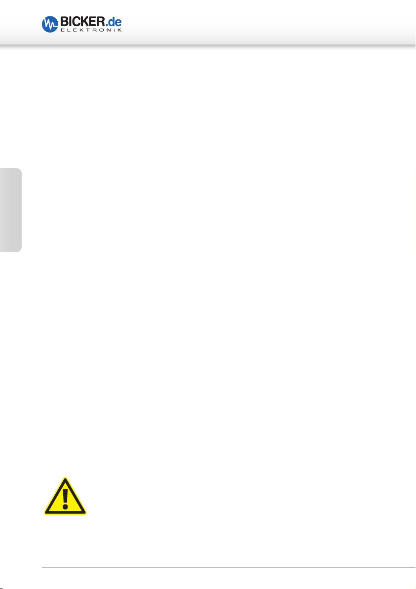
6 Anschlussbeschreibung UPSI-IP-1-Serie
USB interface connector
DC connector 1 DC connector 2
4
3
12
345
4
1
2
1
3
2
UPSI-IP-1-Serie | UPSI- IP-2-Serie
Deutsch
Connector Description Manufacturer Part No.
DC connector 1
(case side) for V
DC connector 2
(case side) for V
USB interface connector
(case side)
DC counter connector 1
(cable side)
DC counter connector 2
(cable side)
USB interface counter
connector (cable side)
IN– (black 2)
IN+ (black 1)
DC connector 1
1 Input (+)
2 Input (–)
3 n.c.
4 FG
IN
OUT
USB
DC connector 2
1 Output (+)
2 Output (–)
3 n.c.
4 FG
RD24 flange plug,
poles 3+PE
RD24 flange socket,
poles 3+PE
Snap-in flange
socket, 5 poles
RD24 cable socket,
poles 3+PE
RD24 cable plug,
poles 3+PE
Snap-in cable plug,
5 poles
OUT– (black 2)
OUT+ (black 1)
USB interface connector
1 Data (–)
2 +5 V
3 GND
4 Shielding
5 Data (+)
Binder Connector 09 4223 150 04
Binder Connector 09 4224 00 04
Binder Connector 99 9116 00 05
Binder Connector 99 0210 00 04
Binder Connector 99 0209 00 04
Binder Connector 99 9113 02 05
8
Page 9

UPSI-IP-1-Serie | UPSI- IP-2-Serie
Anschlussbeschreibung UPSI-IP-2-Serie
USB interface connector
DC connector 1 DC connector 2
1
4
2
3 3
12
345
IN– (black 2) OUT– (black 2)
4
1
2
Deutsch
IN+ (black 1) OUT+ (black 1)
DC connector 1
1 Input (+)
2 Input (–)
3 n.c.
4 FG
USB
DC connector 2
1 Output (+)
2 Output (–)
3 n.c.
4 FG
USB interface connector
1 Data (–)
2 +5 V
3 GND
4 Shielding
5 Data (+)
Connector Description Manufacturer Part No.
DC connector 1
(case side) for V
IN
DC connector 2
(case side) for V
OUT
USB interface connector
(case side)
DC counter connector 1
(cable side)
DC counter connector 2
(cable side)
USB interface counter
connector (cable side)
RD24 flange plug,
poles 3+PE
RD24 flange socket,
poles 3+PE
Snap-in flange
socket, 5 poles
RD24 cable socket,
poles 3+PE
RD24 cable plug,
poles 3+PE
Snap-in cable plug,
5 poles
Binder Connector 09 4223 150 04
Binder Connector 09 4224 00 04
Binder Connector 99 9116 00 05
Binder Connector 99 0210 00 04
Binder Connector 99 0209 00 04
Binder Connector 99 9113 02 05
9
Page 10

UPSI-IP-1-Serie | UPSI- IP-2-Serie
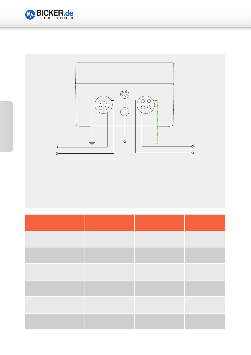
7 Dimensionierung der vorgeschalteten Stromversorgung
Es ist darauf zu achten, dass die Quelle korrekt dimensioniert ist und genug Strom liefert,
um den Ladevorgang und die Funktion der Applikation zu garantieren. Die UPSI reduziert
je nach Last den Ladestrom. Es muss jedoch dafür gesorgt werden, dass auch bei höherer
Last geladen wird. Daraus ergeben sich folgende Mindestanforderungen an die Quelle in
Abhängigkeit von der Last.
Deutsch
I
CHARGE/DISCHARGE
12 V or 24 V
I
[A]
LOAD
[A]
Application
Input source
12 V or 24 V
I
[A]
IN TOTAL
UPSI
Batterypack
UPSI-1208IP-11U / UPSI-1208IP-23U
[A] I
I
LOAD
CHARGE
[A] I
IN TOTAL
[A] P
0 4 4 48
1 5 5 60
2 3,6 5.6 67
3 3,2 6.2 75
4 3 7 84
5 2.5 7.5 90
6 2.2 8.2 99
7 1.8 8.8 106
8 1.5 9.5 114
IN TOTAL
[W]
10
Page 11
UPSI-IP-1-Serie | UPSI- IP-2-Serie
UPSI-2406IP-12U / UPSI-2406IP-24U / UPSI-2406IP-26U
[A] I
I
LOAD
CHARGE
[A] I
IN TOTAL
[A] P
IN TOTAL
[W]
0 3 3 72
1 3 4 96
2 2.7 4.7 113
3 2.5 5.5 132
4 2.2 6.2 149
5 2 7 168
6 1.5 7.5 180
Optionaler Weitbereichseingang: Bei den Geräten UPSI-1208IP-23UW, UPSI-2406IP-24UW
und UPSI-2406IP-26UW ist der UPSI ein DC/DC-Wandler vorangeschaltet, sodass hier
Eingangsstrom I
nicht pauschal angegeben werden kann. Die Eingangsspannung variiert
IN
zwischen 7 bzw. 8 und 36 V, in Abhängigkeit dazu verändert sich hier der Eingangsstrom.
Hinzu kommt noch, je nach Eingangs- und Ausgangsspannung, eine Verlustleistung
P
(umgewandelt in Wärme) des DC/DC-Wandlers von max. 10 % P
DC/DC
Dadurch kann nur die Maximaleingangsleistung P
angegeben werden:
IN TOTAL
CHARGE+LOAD
Deutsch
.
7/8…36 V 12 V or 24 V12 V or 24 V
I
[A]I
IN TOTAL
DC/DC converter UPSI
CHARGE+LOAD
[A]
I
CHARGE/DISCHARGE
Batterypack
I
[A]
LOAD
[A]
ApplicationInput source
11
Page 12

Deutsch
UPSI-IP-1-Serie | UPSI- IP-2-Serie
UPSI-1208IP-23UW
I
[A] I
LOAD
CHARGE
[A] I
CHARGE+LOAD
[A] P
CHARGE+LOAD
[W] P
IN TOTAL
0 4 4 48 52
1 5 5 60 66
2 3.6 5.6 67 74
3 3.2 6.2 75 82,5
4 3 7 84 92,5
5 2.5 7.5 90 100
6 2.2 8.2 99 110
7 1.8 8.8 106 127
8 1.5 9.5 114 127
UPSI-2406IP-24UW
I
[A] I
LOAD
CHARGE
[A] I
CHARGE+LOAD
[A] P
CHARGE+LOAD
[W] P
IN TOTAL
0 3 3 72 80
1 3 4 96 107
2 2.7 4.7 113 126
3 2.5 5.5 132 147
4 2.2 6.2 149 165
5 2 7 168 171
5.42 1.4 7.4 178 187
[W]
[W]
UPSI-2406IP-26UW
I
[A] I
LOAD
CHARGE
[A] I
CHARGE+LOAD
[A] P
CHARGE+LOAD
[W] P
IN TOTAL
[W]
0 3 3 72 80
1 3 4 96 107
2 2.7 4.7 113 126
3 2.5 5.5 132 147
4 2.2 6.2 149 165
4.6 2.15 6.75 162 175
12
Page 13

UPSI-IP-1-Serie | UPSI- IP-2-Serie
8 Inbetriebnahme
Es muss sichergestellt sein, dass das Gerät ordnungsgemäß verbaut ist. Wird danach
an der linken Eingangsbuchse eine Spannung größer als 12 V (UPSI-1208IP-11U / -23U)
oder größer als 23 V (UPSI-2406IP-12U / -24U / -26U) bzw. zwischen 7/8 und 36 V
(UPSI-1208IP-23UW / UPSI-2406IP-24UW / -26UW) angeschlossen, wird der Batteriepack
abgefragt und übermittelt seine Daten. Ist die Eingangsspannung korrekt angeschlossen,
wird der Batteriepack abgefragt und gibt den Pack über das System Present frei. Erst
danach wird auch der Lader für den Akkupack freigegeben und das Laden des Packs
beginnt. Dies geschieht innerhalb weniger Millisekunden.
Die angelegte Spannung am Eingang wird, verringert durch einen stromabhängigen
Spannungsabfall sowie die Länge der Leitungen, an den Ausgang weitergeleitet. Das
Gerät lädt den Energiespeicher und überwacht die Spannungsschwellen am Eingang
(USV-Funktion). It should be noted that at high load / high charging current in combination with long lines (up to 3m in length) up to 1 V and more can fall over these lines.
Es muss an der Quelle stets eine ausreichende Spannung eingestellt sein,
um diesen Abfall auszugleichen. Auch wirkt sich der Spannungsabfall auf die
Spannungsübernahmeschwelle aus. Obwohl die USV (12-V-Version) z. B. bei 11 V schon
in den UPS Betrieb geht, erscheint bei langen Leitungslängen und hohen Strömen nach
Spannungsabfall die Spannung deutlich verringert an der Last. Somit sinkt die Spannung
dann während einer Übernahme z. B. auf 10 V für einige µs statt der eingestellten 11 V
an der USV. Bei entsprechend hoher Last / hohem Ladestrom bzw. langen Leitungen
kann eine einwandfreie Funktion nicht mehr gewährleistet werden. Grund hierfür ist,
dass der Schwellenwert der Eingangsspannung unterschritten wird. Ebenso ist darauf
zu achten, dass die Quelle genug Strom liefert, um den Ladevorgang zu garantieren.
Dies gilt ebenso für die Versionen mit Weitbereichseingang (DC/DC-Wandler vor UPSI
vorangeschaltet). Dabei darf die Spannung an den Eingangsklemmen des Wandlers
6 V nicht unterschreiten (deswegen min. 7 V
kleineren Eingangsspannungen u. U. der Spannungsabfall noch höher ausfallen.
bzw. 8 V
IN
bei –UW Geräten). Hier kann bei
IN
Deutsch
13
Page 14

9 Anschlussplan
VIN+
VIN-
FG
FG
VOUT-
VOUT+
Erdnocken im Gehäuse
UPSI-1208/-2406
Bateriepack:
•
BP-LFP-1025 oder
•
BP-LFP-1325 oder
•
BP-SUC-10066 oder
•
BP-SUC-16090 oder
•
BP-LFP-1375
4 (LiFePO4) oder 5 (EDLC) BAT DATA
Anschlussplan
UPSI-1208IP-11U / UPSI-2406IP-12U
UPSI-1208IP-23U / UPSI-2406-24U / UPSI-2406IP-26U
Deutsch
UPSI-IP-1-Serie | UPSI- IP-2-Serie
14
Page 15

UPSI-IP-1-Serie | UPSI- IP-2-Serie
10 Sicherheitsmaßnahmen
Nach dem Trennen der Versorgung läuft das Gerät für einige Zeit nach Unterschreitung
des Lastsensors weiter (Einstellung eines Schwellwerts für den Lastsensor: Ströme unter
diesem Wert werden als „keine Last“ gewertet und die USV nach eingestellter Zeit abgeschaltet).
Ein Kurzschluss direkt am Ausgang des Geräts kann zur Schädigung oder Zerstörung führen. Erst ab einer bestimmten Impedanz (L > 50 nH, R > 50 mΩ) kann ein Schutz gewährleistet werden.
Warnung!
Missachtung nachfolgender Punkte kann einen elektrischen Schlag,
Brände, schwere Unfälle oder Tod zur Folge haben.
1. Die Eingangsspannung muss vor Installations-, Wartungs-
oder Änderungsarbeiten am Gesamtsystem abgeschaltet
und gegen unbeabsichtigtes Wiedereinschalten gesichert
werden.
Deutsch
2. Auf einen ordnungsgemäßen und fachgerechten Anschluss
muss geachtet werden.
3. Änderungen oder Reparaturversuche am Gerät sind zu
unterlassen.
4. Die Einwirkung von Fremdkörpern, wie z.B. Metallteile ,
auf das Gerät ist zu vermeiden.
11 Ladezeit
Die Ladezeiten sind abhängig vom Energiespeicher, der Eingangsspannung und dem
Laststrom.
15
Page 16

UPSI-IP-1-Serie | UPSI- IP-2-Serie
12 Verpolung / Überlast / Kurzschluss / Übertemperatur
Die Geräte sind gegen Verpolung bei Inbetriebnahme (Gerät aus, nicht aktiv) geschützt
(gilt nur für U-Geräte, nicht -UW). Befinden sich diese im laufenden Backup-Betrieb, ist kein
Verpolschutz gegeben. Im Falle eines zu hohen Stromes (ca. 130-160 % des Nominalwerts
des Standard-Geräts) schaltet das Gerät ab und läuft automatisch weiter, sobald sich der
Ausgangsstrom wieder im spezifizierten Bereich befindet bzw. die Überlast nicht mehr
anliegt. Ein Startversuch erfolgt jede Sekunde (non-Latch, timer 1s). Die Auswirkungen
eines Kurzschlusses auf das Gerät sind abhängig von der Leitungslänge / Querschnitt
(Impedanz) der Ausgangsverdrahtung.
Alle UW-Geräte verfügen zudem über einen Übertemperatur-Schutz (OTP des vorangeschalteten DC/DC-Wandlers). Dieser aktiviert sich, sobald die Temperatur des Sensors
über einen außerhalb der Spezifikation betriebenen Wert steigt. Geschieht dies, schaltet
Deutsch
der DC/DC-Wandler den Ausgang (zur UPSI-Platine) ab und wird erst wieder aktiviert,
wenn die gemessene Temperatur am Sensor unterhalb des Schwellwertes sinkt.
13 Überbrückungszeiten
Die nominalen Überbrückungszeiten können den Datenblättern entnommen werden.
Die Energiespeicher weisen unterschiedliche Eigenschaften auf, ein wichtiger Aspekt
davon ist die Umgebungstemperatur. Bei extrem niedrigen oder hohen Temperaturen
kann es (insbesondere bei Li-Ion-Batteriepacks) zu einer Minderung der nominalen
Überbrückungszeit kommen.
14 Verhalten bei Überschreiten der maximalen Pufferzeiten
Beim Überschreiten der gegebenen Überbrückungszeiten wird der Ausgang anhand der
Entladespannung des entsprechenden Speichers getrennt (Tiefentladeschutz). Bei den
Superkondensatoren, die nicht empfindlich auf eine Tiefentladung reagieren, wurde eine
Schwelle festgelegt, die durch den Strom begrenzt wird. Je niedriger die Spannung, desto
höher der Strom an den Kondensatoren bei konstanter Ausgangsleistung.
Wenn über 70 % des maximal zulässigen Ausgangsstroms während des Entladens der
Superkondensatoren gezogen wird, schaltet der Wandler zunächst ab, ohne den Ausgang
sofort zu trennen und eine niedrigere Spannung erscheint am Ausgang (Zustand <2s).
Dieser Zustand sollte vermieden werden, indem das System rechtzeitig heruntergefahren
wird, bevor die Superkondensatoren unter hohen Strömen entladen werden.
16
Page 17

UPSI-IP-1-Serie | UPSI- IP-2-Serie
15 Status LED
2 x blinken, Pause 1,5s Status: Es wird Kapazität zum Starten benötigt,
Zustand Laden
3 x blinken, Pause 1,5s Status Herunterfahren: Warten bis System herunter-
gefahren ist
4 x blinken, Pause 1,5s Status Neustart: Ausgang ist abgeschaltet und Zeit
läuft bis Neustart (Rebootphase)
5 x blinken, Pause 1,5s Status: Keine Batterie erkannt / Batterie defekt
1 Hz Blinken Netzausfall Status: Batteriebetrieb
Dauer An Status: System OK
Deutsch
Schnelles Blinken Status: Ausgangsspannung zu gering
USV wird abgeschaltet
17
Page 18

UPSI-IP-1-Serie | UPSI- IP-2-Serie
16 Empfehlungen für eine lange Lebensdauer des USV-Systems
Supercaps haben kein tatsächliches „End of Life“ (EOL). Über die Zeit verringert sich
die Kapazität und der ESR (Ersatzserienwiderstand) erhöht sich. Jedoch wird oft als EOL
eine Verringerung der Kapazität auf 70 % und eine Verdopplung des ESR definiert. Ein
wichtiger Aspekt für die Alterung der Supercaps ist die Ladeschlussspannung und die
Betriebstemperatur.
Li-Ionen-Akkus altern ebenfalls über die Zeit in Abhängigkeit von Zyklen, Betriebstemperatur und Höhe der Ladeschlussspannung.
Die Ladeschlussspannungen sind so optimiert, dass diese ein optimales Maß
zwischen Lebensdauer und Performance bilden.
Um die Lebensdauer des Systems zu verlängern, sollten die Geräte nicht in der Nähe von
Deutsch
Hitzequellen platziert werden. Beim Einsatz der Geräte in Kombination mit LiFePO4-Akku
sollte immer eine größere Kapazität als tatsächlich benötigt verwendet werden. Je weniger tief die Packs entladen werden, desto höher ist die Lebensdauer.
17 Wartung
Die USV enthält keine zu wartenden Teile. Im Fehlerfall sollten die Stromquelle ausgeschaltet
und die Kabel getrennt werden.
18 Entsorgung
Elektrische und elektronische Geräte dürfen nicht in den Hausmüll! Die Entsorgung
von Produkten, welche das Ende ihrer Lebenszeit erreicht haben, muss gemäß den
geltenden gesetzlichen Vorschriften erfolgen. Li-Ionen- bzw. LiFePO4-Speicherpacks
können über den Hersteller (Bicker Elektronik) entsorgt werden. Supercap-Packs
dürfen in den normalen Elektroschrott.
19 Haftungsausschluss
Wir, die Bicker Elektronik GmbH, haben den Inhalt der Druckschrift auf Übereinstimmung
mit der beschriebenen Hard- und Software geprüft. Dennoch können Abweichungen nicht
ausgeschlossen werden, sodass wir für die vollständige Übereinstimmung keine Gewähr
übernehmen. Die Angaben in dieser Druckschrift werden regelmäßig überprüft, notwendige
Korrekturen sind in den aktualisierten Versionen enthalten.
18
Page 19

UPSI-IP-1-Serie | UPSI- IP-2-Serie
20 Software
Die USV wird als „Human-Interface-Device“ (HID-Batterie, HID-VCom) unter Windows
erkannt, wenn diese über USB angeschlossen wird. Als HID-Batterie wird für das
Herunterfahren des Betriebssystems keine zusätzliche Software benötigt und kann
dadurch mit den internen Akku-Einstellungen des Betriebssystems gesteuert werden.
Falls ein Herunterfahren nach Zeit gewünscht ist, kann mit der Software „UPSI HID-Battery
Parameter Settings“ die Funktion aktiviert und die gewünschte Überbrückungszeit
eingestellt werden. Das Herunterfahren des Betriebssystems steuert komplett die UPSI
Hardware, die Software kann nach einstellen der Parameter geschlossen bleiben.
Deutsch
19
Page 20

20 Software
Deutsch
UPSI-IP-1-Serie | UPSI- IP-2-Serie
Device Information
Beschreibung
Anzeige –
keine Einstellungen möglich
Input Voltage Eingangsspannung – wird nur im Normalbetrieb angezeigt
Output Voltage Ausgangsspannung – wird immer angezeigt
Output Current Strom der Applikation
Battery Voltage Spannung am Akkupack
Battery Current Strom am Akkupack
State of Charge Akku-Ladezustand
Runtime to Empty Restlaufzeit unter aktuellen Lastbedingungen
Runtime to Full Ladezeit bis 100 % geladen
20
Page 21

UPSI-IP-1-Serie | UPSI- IP-2-Serie
20 Software
Parameter
einstellbar
Load Sensor 100mA…800mA
Shutdown
System after
Maximum
Backup Time
Need capacity
before power up
Ignition Timer Nicht verfügbar für IP-Modelle
Wertebereich/
Einheit
in mA-schritten
1s…3600s
in s-schritten
1s…3600s
in s-schritten
1%...100%
in 1%-schritten
Beschreibung
Stromwert, dessen Unterschreitung zur Annahme führt,
dass das zu versorgende System aus ist. Das System wird
daraufhin für x Sekunden (Restart Delay) getrennt, um die
Neustart-Funktion durchzuführen, falls die Eingangsspannung zurückgekehrt ist.
Betrit die Überbrückungszeit: Während dieser Zeit wird die
Versorgung des Systems aufrecht erhalten. Nach Ablauf dieser Zeit und weiterhin fehlender Eingangsversorgung wird
der Shutdown-Prozess am PC initiiert. Wenn innerhalb dieser Zeit die Spannung netzseitig am Eingang wiederkehrt,
wird nichts unternommen.
Die maximale Überbrückungszeit. Nach dieser Zeit wird das
System getrennt. Diese Einstellung kann eingesetzt werden
für Systeme, die keinen Herunterfahrprozess benötigen
oder für den Fall, dass das System sich aufhängt und hart
getrennt werden muss.
Mindestkapazität für die Freigabe der USV. Hiermit kann sichergestellt werden, dass die Applikation bei einem Ausfall
sicher versorgt werden kann. Die Einschaltzeit kann sich
hierdurch verzögern.
Deutsch
Restart Delay 1s…180s
in s-schritten
Zeitverzögerung nach Trennen des Systems für die er neute
Freigabe der Versorgung. Wenn während des Herunterfahrens oder danach die Versorgung nach einem Ausfall
wiederkehrt, wird das System über die Ausgangsspannung
der USV erneut gestartet.
21
Page 22

20 Software
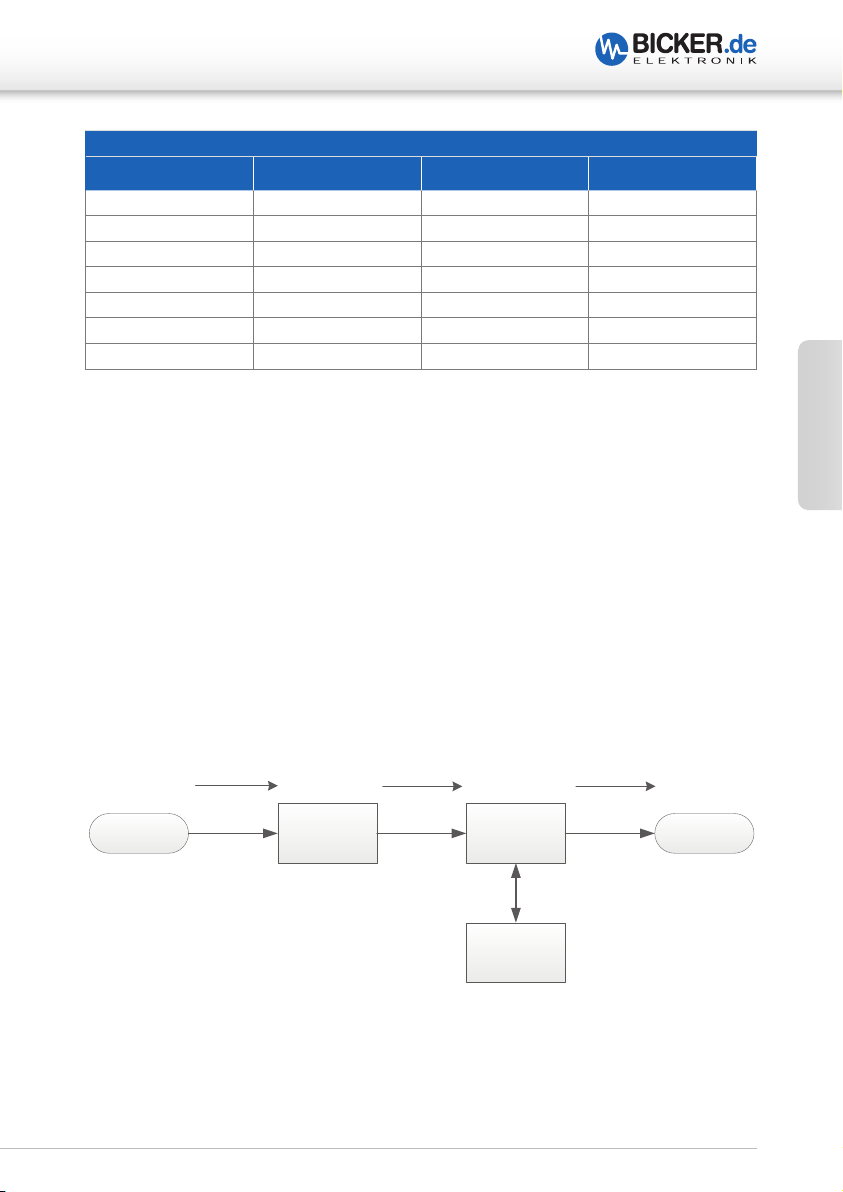
Software-Parameter-Impulsdiagramm
UPSI-IP-1-Serie | UPSI- IP-2-Serie
NORMAL
V
IN
POWER
FAIL
SHUTDOWN
SYSTEM AFTER
APPLICATION CURRENT IS
BELOW LOAD SENSOR
SHUTDOWN
PROCESS
RESTART
DELAY
Deutsch
V
OUT
Zurücksetzen der Parameter
Mit „Reset Parameter…“ werden die Einstellungen auf die Standardwerte zurückgesetzt.
Speichern der Parameter
Mit „Save…“ werden die Einstellungen auf der USV gespeichert. Die Software kann dann
geschlossen werden.
22
Page 23

UPSI-IP-1-Serie | UPSI- IP-2-Serie
21 Befehlsliste
Command Index
INDEX NO. Description
1 Generic
2 Sensors
3 Charge Controller
4 Battery A
5 Battery B
7 Parameter
21.1 Command Index “Generic” 0x01
GetDeviceName() 0x62
This read function returns the device name as string.
Cmd Name Access Type Min. Max Unit
0x62 GetDeviceName() R char[ ] - - -
Transfer packet: 0x01 0x03 0x01 0x62 0x04
Deutsch
GetFirmwareVersion() 0x63
This read function returns the firmware version as string.
Cmd Name Access Type Min. Max Unit
0x63 GetFirmwareVersion() R char[ ] - - -
Transfer packet: 0x01 0x03 0x01 0x63 0x04
GetConnectedEnergyPack() 0x64
This read function returns the connected energy storage pack as string (P/N).
Cmd Name Access Type Min. Max Unit
0x64 GetConnectedEnergyPack() R char[16] - - -
Transfer packet: 0x01 0x03 0x01 0x64 0x04
23
Page 24

21.2 Command Index “Sensors” 0x02
GetCPUTemperature() 0x00
This read function returns the cpu temperature.
Cmd Name Access Type Min. Max Unit
0x00 GetCPUTemperature() R Int32 0 +150 °C
Transfer packet: 0x01 0x03 0x02 0x00 0x04
GetOutputCurrent() 0x01
This read function returns the output current.
Cmd Name Access Type Min. Max Unit
Deutsch
0x01 GetOutputCurrent () R Int32 0 +32768 mA
Transfer packet: 0x01 0x03 0x02 0x01 0x04
GetInputVoltage() 0x02 (not connected at moment)
This read function returns the input voltage.
Cmd Name Access Type Min. Max Unit
0x02 GetInputVoltage () R Int32 0 +32768 mV
Transfer packet: 0x01 0x03 0x02 0x02 0x04
UPSI-IP-1-Serie | UPSI- IP-2-Serie
21.3 Command Index “Charge Controller” 0x03
GetEnergyStorageVoltage() 0x20
This read-word function returns the measured voltage of the capacitor 1.
Cmd Name Access Type Min. Max Unit
0x20 GetEnergyStorageVoltage () R Int16 0 32768 mV
Transfer packet: 0x01 0x03 0x03 0x20 0x04
24
Page 25

UPSI-IP-1-Serie | UPSI- IP-2-Serie
GetChargeStatusRegister() 0x1B
This read-word function returns the status flags.
Cmd Name Access Type Min. Max Unit
0x1B GetStatusRegister() R Bit Field - - True / False
Transfer packet: 0x01 0x03 0x03 0x1B 0x04
Bit Field:
SD SU CV UV CL RV RV RV RV CC RV PF RV RV RV RV
LSB MSB
BIT Description
0 SD Shows that the device is in step-down (charging) mode.
1 SU Shows that the device is in step-up (backup) mode.
2 CV Shows that the charger is in constant voltage mode.
3 UV Shows that the charger is in undervoltage lockout.
4 CL Shows that the device is in input current limit.
5 RV Reserved Bit
6 RV Reserved Bit
7 RV Reserved Bit
8 RV Reserved Bit
9 CC Shows that the charger is in constant current mode.
10 RV Reserved Bit
11 PF Shows that the input power is failed.
12 RV Reserved Bit
13 RV Reserved Bit
14 RV Reserved Bit
15 RV Reserved Bit
Deutsch
GetInputVoltage() 0x25
This read-word function returns the measured input voltage of the UPS.
Cmd Name Access Type Min. Max Unit
0x25 GetInputVoltage() R Int16 0 32768 mV
Transfer packet: 0x01 0x03 0x03 0x25 0x04
25
Page 26

GetOutputVoltage() 0x27
This read-word function returns the measured output voltage of the UPS.
Cmd Name Access Type Min. Max Unit
0x27 GetOutputVoltage() R Int16 0 32768 mV
Transfer packet: 0x01 0x03 0x03 0x27 0x04
GetInputCurrent() 0x28
This read-word function returns the measured input current of the UPS.
Cmd Name Access Type Min. Max Unit
0x28 GetInputCurrent () R Int16 0 32768 mA
Transfer packet: 0x01 0x03 0x03 0x28 0x04
Deutsch
GetChargeCurrent() 0x29
This read-word function returns the measured charge current of the UPS.
Cmd Name Access Type Min. Max Unit
0x29 GetChargeCurrent () R Int16 -32768 32768 mA
Transfer packet: 0x01 0x03 0x03 0x29 0x04
UPSI-IP-1-Serie | UPSI- IP-2-Serie
21.4 Command Index “Battery A” and “Battery B” 0x04 / 0x05
GetBatteryTemperature() 0x08
This read-word function returns the measured temperature.
Cmd Name Access Type Min. Max Unit
0x08 GetBatteryTemperature() R Uint16 0 65535 0.1°K
Transfer packet: 0x01 0x03 0x04 0x08 0x04
GetBatteryVoltage() 0x09
This read-word function returns the sum of measured cell voltages.
Cmd Name Access Type Min. Max Unit
0x09 GetBatteryVoltage() R Uint16 0 65535 mV
Transfer packet: 0x01 0x03 0x04 0x09 0x04
26
Page 27

UPSI-IP-1-Serie | UPSI- IP-2-Serie
GetBatteryCurrent() 0x0A
This read-word function returns the measured current from the coulomb counter. If the
input to the device exceeds the maximum value, the value is clamped at the maximum
and does not roll over.
Cmd Name Access Type Min. Max Unit
0x0A GetBatteryCurrent() R Int16 -32767 32768 mA
Transfer packet: 0x01 0x03 0x04 0x0A 0x04
GetRelativeStateOfCharge() 0x0D
This read-word function returns the battery charge state in percentage.
Cmd Name Access Type Min. Max Unit
0x0D GetRelativeStateOfCharge() R Uint8 0 100 %
Transfer packet: 0x01 0x03 0x04 0x0D 0x04
GetRunTimeToEmpty() 0x11
This read-word function returns the predicted remaining battery capacity based on the
present rate of discharge. NOTE: 65535 = Battery is not being discharged.
Cmd Name Access Type Min. Max Unit
0x11 GetBatteryRunTimeToEmpty() R Uint16 0 65535 min
Transfer packet: 0x01 0x03 0x04 0x11 0x04
GetAverageTimeToFull () 0x13
This read-word function returns the predicted time-to-full charge based on
AverageCurrent(). NOTE: 65535 = Battery is not being charged.
Cmd Name Access Type Min. Max Unit
0x13 GetBatteryAverageTimeToFull() R Uint16 0 65535 min
Transfer packet: 0x01 0x03 0x04 0x13 0x04
GetBatteryCycleCount() 0x17
This read-word function returns the number of cycles the battery has been loaded.
Cmd Name Access Type Min. Max Unit
0x17 GetBatteryCycleCount () R Uint16 0 65535 cycles
Transfer packet: 0x01 0x03 0x04 0x17 0x04
Deutsch
27
Page 28

GetBatteryDesignCapacity() 0x18
This read-word function returns the nominal capacity.
Cmd Name Access Type Min. Max Unit
0x18 GetBatteryDesignCapacity () R Uint16 0 65535 mAh
Transfer packet: 0x01 0x03 0x04 0x18 0x04
GetBatteryDesignVoltage() 0x19
This read-word function returns the nominal voltage.
Cmd Name Access Type Min. Max Unit
0x19 GetBatteryDesignVoltage() R Uint16 7000 18000 mV
Transfer packet: 0x01 0x03 0x04 0x19 0x04
Deutsch
GetBatteryManufacturerDate() 0x1B
This read-word function returns the pack's manufacturer date.
Cmd Name Access Type Min. Max Unit
0x1B GetBatteryManufacturerDate() R Uint16 0 65535 -
Transfer packet: 0x01 0x03 0x04 0x1B 0x04
NOTE: Value in the following format: Day + Month*32 + (Year–1980)*512
UPSI-IP-1-Serie | UPSI- IP-2-Serie
GetBatterySerialNumber() 0x1C
This read-word function returns the assigned pack serial number.
Cmd Name Access Type Min. Max Unit
0x1C GetBatterySerialNumber() R Uint16 0 65535 -
Transfer packet: 0x01 0x03 0x04 0x1C 0x04
GetBatteryManufacturerName() 0x20
This read-block function returns the pack manufacturer's name.
Cmd Name Access Type Min. Max Unit
0x20 GetBatteryManufacturerName() R Char[20] - - ASCII
Transfer packet: 0x01 0x03 0x04 0x20 0x04
28
Page 29

UPSI-IP-1-Serie | UPSI- IP-2-Serie
GetBatteryDeviceName() 0x21
This read-block function returns the assigned pack name.
Cmd Name Access Type Min. Max Unit
0x21 GetBatteryDeviceName() R Char[20] - - ASCII
Transfer packet: 0x01 0x03 0x04 0x21 0x04
GetBatteryCellVoltage4() 0x3C
This read-word function returns the Cell 4 voltage.
Cmd Name Access Type Min. Max Unit
0x3C GetBatteryCellVoltage4() R Uint16 0 65535 mV
Transfer packet: 0x01 0x03 0x04 0x3C 0x04
GetBatteryCellVoltage3() 0x3D
This read-word function returns the Cell 3 voltage.
Cmd Name Access Type Min. Max Unit
0x3D GetBatteryCellVoltage3() R Uint16 0 65535 mV
Transfer packet: 0x01 0x03 0x04 0x3D 0x04
Deutsch
GetBatteryCellVoltage2() 0x3E
This read-word function returns the Cell 2 voltage.
Cmd Name Access Type Min. Max Unit
0x3E GetBatteryCellVoltage2() R Uint16 0 65535 mV
Transfer packet: 0x01 0x03 0x04 0x3E 0x04
GetBatteryCellVoltage1() 0x3F
This read-word function returns the Cell 1 voltage.
Cmd Name Access Type Min. Max Unit
0x3F GetBatteryCellVoltage1() R Uint16 0 65535 mV
Transfer packet: 0x01 0x03 0x04 0x3F 0x04
29
Page 30

UPSI-IP-1-Serie | UPSI- IP-2-Serie
GetBatteryStateOfHealth() 0x4F (Future use)
This read-word command returns the SoH information of the battery in percentage of
design capacity and design energy.
Cmd Name Access Type Min. Max Unit
0x4F GetBatteryStateOfHealth() R Uint8 0 100 %
Transfer packet: 0x01 0x03 0x04 0x4F 0x04
21.5 Command Index “Parameter” 0x07
Paramter ID Description
Deutsch
ID Description
0 Place holder entry. Do not use!
1 Load sensor parameter (values in mA)
2 Maximum backup time (values in seconds)
Countdown timer to shut down the system when power fail occurs (values in
3
seconds). Only on USB.
4 Delay timer between output disable and output enable (value in seconds).
5 Required minimum capacity to enable output (values in percent).
6 Maximum backup time when using analogue read pin.
Single Parameter Data Format:
The data format: AAbbBBccCCddDDEEffFF
ID Description
AA Parameter ID (Byte)
BBbb Minimum Value (Uint16)
CCcc Maximum Value (Uint16)
DDdd Standard Value (Uint16)
EE Is Active (Byte BOOL)
FFff Value (Uint16)
NOTE: The size of parameter structure is 10 bytes long.
30
Page 31

UPSI-IP-1-Serie | UPSI- IP-2-Serie
GetAllParameter() 0x00
This function returns the complete parameter array (ID 0 to ID 6).
Cmd Name Access Type Min. Max Unit
0x00 GetBatteryDeviceName() R ParameterData[7] - - -
Transfer packet: 0x01 0x03 0x07 0x00 0x04
NOTE: The complete size of transferred data is
(number of id’s) * (size of parameter structure) = 7 * 10 bytes = 70 bytes.
SetParameterIDx() 0x01 to 0x06
This function sets the specified parameter.
Cmd Name Access Type Min. Max Unit
0x01 to
0x06
Transfer packet: 0x01 0x06 0x06 0x[AA] [EEffFF] 0x04
NOTE: To set a parameter, only the AA(Parameter ID), EE(Is Active), ffFF(Value)
have to transfer! (4 bytes long)
Set Data Format: EEffFF
GetBatteryDeviceName() W ParameterData - - -
Deutsch
31
Page 32

English
UPSI-IP-1 series | UPSI- IP-2 series
UPSI-IP-1
UPSI-IP-2
32
Page 33

UPSI-IP-1 series | UPSI- IP-2 series
1 Product and function description ...................................................4
2 Read carefully before initial operation ...........................................4
3 Intended use – description ...............................................................5
4 Assembly and installation advice ....................................................7
5 Convection and installation position ..............................................7
6 Description of connectors .................................................................8
7 Dimensioning the upstream power supply ................................ 10
8 Initial operation ................................................................................ 13
9 Connecting diagram ........................................................................ 14
10 Preventive measures ....................................................................... 15
11 Charging time ................................................................................... 15
12 Reverse polarity / overload / short circuit / overtemperature .. 16
13 Backup times..................................................................................... 16
14 Behaviour in case of exceeding maximum backup time ......... 16
15 Status LED.......................................................................................... 17
16 Recommendations for a long UPS service life ........................... 18
17 Maintenance ..................................................................................... 18
18 Disposal.............................................................................................. 18
19 Disclaimer .......................................................................................... 18
20 Software ............................................................................................. 19
21 List of commands ............................................................................. 23
English
33
Page 34

UPSI-IP-1 series | UPSI- IP-2 series
Congratulations for choosing a quality product!
This manual shall help the user to get familiar with the product and its components and
features. It shall provide information as accurately and completely as possible. However,
for possible errors no liability can be assumed. Hints to existing mistakes, critics and
suggestions for improvement are welcome at any time.
1 Product and function description of UPSI-IP-1
and UPSI-IP-2 series
UPSI-IP-1 and UPSI-IP-2 series (hereinafter called UPS) are combined 12 V or 24 V DC/DC
English
UPS systems with an already attached storage device included. They have numerous
digital features and high performance and are designed for outdoor use or use in more
extreme conditions. They are based on the UPSI-1208/-2406 technologies. The different
storage media (hereinafter called battery packs, accu packs etc.) are either Supercap or
LiFePO4 packs. Furthermore, some versions of the UPSI-IP-2 devices have an additional
DC/DC converter (-xxUW) upstream of the UPS board. This allows working with widerange input (7 or 8…36 V DC). An overview of the different variants as well as the electrical
and technical data can be found on page XX or in the data sheets.
2 Read carefully before initial operation!
This manual as well as all datasheets and safety instructions must be read and followed
strictly before installation. Otherwise in certain situations warranty and guarantee can be
cancelled partly or completely.
Take care while handling!
Even after disconnecting the upstream source and also no voltage is
measurable at the output, the UPS can be still powered by the storage
medium.
34
Page 35

UPSI-IP-1 series | UPSI- IP-2 series
3 Intended use – description
This device is built for use under difficult and extreme environmental conditions. The
device is intended for professional use in applications such as industrial control, office,
communication and measurement technology. It must not be used in devices or equipment where a malfunction will cause serious injury or endanger human life.
The functional purpose of the UPS is bypassing short-term and long-lasting power
failures and/or fluctuations. However, it may also be used for user-scheduled powerdowns of mains and cycles, e.g. replacing larger batteries in vehicles, while continuing
to power the electronics, opening or closing safety valves after a malfunction or shutting
down a system. As storage media, which are also mounted in the product housing in
addition to the UPS board, serve in series and / or parallel connected supercapacitors
(also called supercaps, ultracapacitors or EDLC) or Li-ion battery packs with LiFePO4
technology.
An important characteristic of the UPS is the fact, that the output voltage is constantly
regulated during backup operation without dropping when the accu voltage decreases.
For an increase of lifetime the batterypacks will be charged quick by optimized charging
algorithms.
English
The main difference between the UPSI-IP-1 / IP-2 devices and the standard models UPSI1208 / -2406 / UPSI-1208D / -2406D (for DIN rail mounting) is that the housings have IP67
protection. This means that the components inside (UPS board, storage medium and
DC / DC converter + filter board (just -xxUW devices)) are completely protected against
contact and dust (IP6x) as well as against water penetration during temporary immersion
(IPx7). It is expressly pointed out that the devices are not suitable for permanent operation
under water!
35
Page 36

UPSI-IP-1 series | UPSI- IP-2 series
English
UPSI version Input Output Power Storage type Chassis
UPSI-2406IP-26UW** 8…36 V DC Normal: 23.5 V DC
Backup: 23.5 V DC
Backup: 23.5 V DC
Backup: 23.5 V DC
in
- 1 V (Full load)
6 A / 144 W max. BP-LFP-1375 IP-2 Typ
4.6 A / 110 W max. BP-LFP-1375 IP-2 Typ
UPSI-2406IP-24U 24 V DC Normal: V
Backup: 23.5 V DC
Backup: 12 V DC
in
- 1 V (Full load)
6 A / 144 W max. BP-SUC-16090 IP-2 Typ
5.42 A / 130 W max. BP-SUC-16090 IP-2 Typ
UPSI-2406IP-24UW 8…36 V DC Normal: 23.5 V DC
UPSI-2406IP-26U** 24 V DC Normal: V
UPSI-1208IP-23U 12 V DC Normal: V
UPSI-1208IP-23UW 7…36 V DC Normal: 11.5 V DC
Backup: 23.5 V DC
Backup: 12 V DC
in
- 1 V (Full load)
8 A / 96 W max. BP-SUC-10066 IP-2 Typ
8 A / 96 W max. BP-SUC-10066 IP-2 Typ
UPSI-1208IP-11U 12 V DC Normal: V
UPSI-2406IP-12U 24 V DC Normal: V
Backup: 12 V DC
in
in
- 1 V (Full load)
- 1 V (Full load)
6 A / 144 W max. BP-LFP-1325 IP-1 Typ
8 A / 96 W max. BP-LFP-1025 IP-1 Typ
Overview of all UPSI-IP versions
(202 x 232 x 110 mm)
36
(202 x 232 x 110 mm)
(202 x 232 x 110 mm)
(202 x 232 x 110 mm)
(202 x 232 x 110 mm)
(140 x 140 x 90 mm)
(202 x 232 x 110 mm)
(140 x 140 x 90 mm)
Page 37

UPSI-IP-1 series | UPSI- IP-2 series
4 Assembly and installation advice
Installation and operation of this device is only allowed to be executed from
qualified personnel. They should preferably be mounted and operated in designated
locations such as walls, control cabinets, warehouses, etc. at temperatures specified in
the data sheet. Pay attention to correct polarity! During the mounting process all connecting cables to the UPS must be firmly connected and separated from any power.
5 Convection and installation position
The units can be installed horizontally as well as vertically (possible connections at the
top and bottom). However, horizontal overhead mounting is not recommended due to
heavy components in the bottom of the housing. Basically, the devices can be operated
without external air circulation. This means that the aluminum housing does not need
to be directly cooled by fans and no otherwise ventilation is needed. Nevertheless, care
should be taken to ensure sufficient convection, so that the generated heat can be dissipated. The models with wide-range input (-xxUW) additionally include a DC / DC converter board, which is the only component inside the housing that is attached by means
of a GapPad® and thereby passively cooled. Here, the generated heat is dissipated to the
outside via the housing. It should be noted that adjacent devices (e.g. in control cabinets
or systems) can become foreign-heated.
English
37
Page 38

6 Description of connectors UPSI-IP-1 series
USB interface connector
DC connector 1 DC connector 2
4
3
12
345
4
1
2
1
3
2
UPSI-IP-1 series | UPSI- IP-2 series
English
Connector Description Manufacturer Part No.
DC connector 1
(case side) for V
DC connector 2
(case side) for V
USB interface connector
(case side)
DC counter connector 1
(cable side)
DC counter connector 2
(cable side)
USB interface counter
connector (cable side)
IN– (black 2)
IN+ (black 1)
DC connector 1
1 Input (+)
2 Input (–)
3 n.c.
4 FG
IN
OUT
USB
DC connector 2
1 Output (+)
2 Output (–)
3 n.c.
4 FG
RD24 flange plug,
poles 3+PE
RD24 flange socket,
poles 3+PE
Snap-in flange
socket, 5 poles
RD24 cable socket,
poles 3+PE
RD24 cable plug,
poles 3+PE
Snap-in cable plug,
5 poles
OUT– (black 2)
OUT+ (black 1)
USB interface connector
1 Data (–)
2 +5 V
3 GND
4 Shielding
5 Data (+)
Binder Connector 09 4223 150 04
Binder Connector 09 4224 00 04
Binder Connector 99 9116 00 05
Binder Connector 99 0210 00 04
Binder Connector 99 0209 00 04
Binder Connector 99 9113 02 05
38
Page 39

UPSI-IP-1 series | UPSI- IP-2 series
Description of connectors UPSI-IP-2 series
USB interface connector
DC connector 1 DC connector 2
1
4
2
3 3
12
345
IN– (black 2) OUT– (black 2)
4
1
2
English
IN+ (black 1) OUT+ (black 1)
DC connector 1
1 Input (+)
2 Input (–)
3 n.c.
4 FG
USB
DC connector 2
1 Output (+)
2 Output (–)
3 n.c.
4 FG
USB interface connector
1 Data (–)
2 +5 V
3 GND
4 Shielding
5 Data (+)
Connector Description Manufacturer Part No.
DC connector 1
(case side) for V
IN
DC connector 2
(case side) for V
OUT
USB interface connector
(case side)
DC counter connector 1
(cable side)
DC counter connector 2
(cable side)
USB interface counter
connector (cable side)
RD24 flange plug,
poles 3+PE
RD24 flange socket,
poles 3+PE
Snap-in flange
socket, 5 poles
RD24 cable socket,
poles 3+PE
RD24 cable plug,
poles 3+PE
Snap-in cable plug,
5 poles
Binder Connector 09 4223 150 04
Binder Connector 09 4224 00 04
Binder Connector 99 9116 00 05
Binder Connector 99 0210 00 04
Binder Connector 99 0209 00 04
Binder Connector 99 9113 02 05
39
Page 40

UPSI-IP-1 series | UPSI- IP-2 series
7 Dimensioning the upstream power supply
Pay attention that the source is correctly dimensioned and supplies enough current to
ensure the charging process and the function of the application. The UPSI reduces its
charging current depending on the load. However, care must be taken to ensure that
the battery pack can be charged even at maximum load. This results in the following
minimum requirements for the PSU source depending on the load:
English
I
CHARGE/DISCHARGE
12 V or 24 V
I
[A]
LOAD
[A]
Application
Input source
12 V or 24 V
I
[A]
IN TOTAL
UPSI
Batterypack
UPSI-1208IP-11U / UPSI-1208IP-23U
[A] I
I
LOAD
CHARGE
[A] I
IN TOTAL
[A] P
0 4 4 48
1 5 5 60
2 3,6 5.6 67
3 3,2 6.2 75
4 3 7 84
5 2.5 7.5 90
6 2.2 8.2 99
7 1.8 8.8 106
8 1.5 9.5 114
IN TOTAL
[W]
40
Page 41

UPSI-IP-1 series | UPSI- IP-2 series
UPSI-2406IP-12U / UPSI-2406IP-24U / UPSI-2406IP-26U
[A] I
I
LOAD
CHARGE
[A] I
IN TOTAL
[A] P
IN TOTAL
[W]
0 3 3 72
1 3 4 96
2 2.7 4.7 113
3 2.5 5.5 132
4 2.2 6.2 149
5 2 7 168
6 1.5 7.5 180
Optional wide-range input: The UPS devices UPSI-1208IP-23UW, UPSI-2406IP-24UW and
UPSI-2406IP-26UW are equipped by an upstream DC/DC converter so that the input
current I
can not be specified sweepingly. The input voltage varies between 7 or 8 and
IN
36 V and so input current is changing correspondingly. Depending on the input and
output voltage, there is a power loss P
of max. 10 % P
CHARGE +LOAD
, too. As a result, only the maximum input power P
(converted into heat) of the DC / DC converter
DC/DC
IN TOTAL
can
be specified:
English
7/8…36 V 12 V or 24 V12 V or 24 V
I
[A]I
IN TOTAL
DC/DC converter UPSI
CHARGE+LOAD
[A]
I
CHARGE/DISCHARGE
Batterypack
I
[A]
LOAD
[A]
ApplicationInput source
41
Page 42

English
UPSI-IP-1 series | UPSI- IP-2 series
UPSI-1208IP-23UW
I
[A] I
LOAD
CHARGE
[A] I
CHARGE+LOAD
[A] P
CHARGE+LOAD
[W] P
IN TOTAL
0 4 4 48 52
1 5 5 60 66
2 3.6 5.6 67 74
3 3.2 6.2 75 82,5
4 3 7 84 92,5
5 2.5 7.5 90 100
6 2.2 8.2 99 110
7 1.8 8.8 106 127
8 1.5 9.5 114 127
UPSI-2406IP-24UW
I
[A] I
LOAD
CHARGE
[A] I
CHARGE+LOAD
[A] P
CHARGE+LOAD
[W] P
IN TOTAL
0 3 3 72 80
1 3 4 96 107
2 2.7 4.7 113 126
3 2.5 5.5 132 147
4 2.2 6.2 149 165
5 2 7 168 171
5.42 1.4 7.4 178 187
[W]
[W]
UPSI-2406IP-26UW
I
[A] I
LOAD
CHARGE
[A] I
CHARGE+LOAD
[A] P
CHARGE+LOAD
[W] P
IN TOTAL
[W]
0 3 3 72 80
1 3 4 96 107
2 2.7 4.7 113 126
3 2.5 5.5 132 147
4 2.2 6.2 149 165
4.6 2.15 6.75 162 175
42
Page 43

UPSI-IP-1 series | UPSI- IP-2 series
8 Initial operation
Ensure that the UPS is correctly installed. When at the left input jack an input voltage higher than 12 V (UPSI-1208IP-11U / -23U) or 23 V (UPSI-2406IP-12U / -24U / -26U),
between 7/8 and 36 V (UPSI-1208IP-23UW / UPSI-2406IP-24UW / -26UW), respectively,
is connected, the battery pack gets queried and transmits its data. If the input voltage
is connected correctly, the battery pack gets queried and clears the pack via System
Present. Only then the charger gets enabled and the charging of the battery pack starts.
This process lasts only a few milliseconds.
The applied voltage at the input of the UPS is passed through to the output, reduced by a
current-dependent voltage drop as well as the cable length. The device charges the energy storage and monitors the upstream voltage thresholds at the input (UPS function). It
should be noted that at high load / high charging current in combination with long lines
(up to 3 m in length) up to 1 V and more can drop over these lines.
There must always be sufficient voltage at the source to balance this voltage drop. The
voltage drop also affects the voltage acceptance threshold. For example, although the
UPS (12 V version) is already in UPS operation at 11 V, the voltage on the load after a voltage drop appears significantly reduced when there are long lines in combination with
high currents. Thus, the voltage on the UPS then drops during a takeover, e.g. to 10 V for
a few μs instead of the set 11 V. With a correspondingly high load / high charging current
or long lines, a perfect function can no longer be guaranteed. The reason for this ist, that
the threshold value of the input voltage falls below. Also make sure that the source provides enough power to guarantee the charging process. This also applies to versions with
wide-range input (DC / DC converter upstream of UPSI). The voltage at the input terminals
of the converter must not fall below 6 V (therefore at least 7 V
or 8 VIN for -UW devices).
IN
Under certain circumstances, the voltage drop may be even higher at lower input voltages.
English
43
Page 44

9 Connecting diagram
VIN+
VIN-
FG
FG
VOUT-
VOUT+
Erdnocken im Gehäuse
UPSI-1208/-2406
Bateriepack:
•
BP-LFP-1025 oder
•
BP-LFP-1325 oder
•
BP-SUC-10066 oder
•
BP-SUC-16090 oder
•
BP-LFP-1375
4 (LiFePO4) oder 5 (EDLC) BAT DATA
Anschlussplan
UPSI-1208IP-11U / UPSI-2406IP-12U
UPSI-1208IP-23U / UPSI-2406-24U / UPSI-2406IP-26U
UPSI-1208IP-23UW / UPSI-2406IP-24UW / UPSI-2406IP-26UW
English
UPSI-IP-1 series | UPSI- IP-2 series
Connecting diagram
input lter PSZ-1040 DC/DC converter DC160WS
grounding screws in chassis
Storage media
· BP-SUC-10066 or
· BP-SUC-16090 or
· BP-LFP-1375
44
Connecting diagram
UPSI-1208IP-11U / UPSI-2406IP-12U / UPSI-1208IP-23U /
UPSI-2406IP-24U / UPSI-2406IP-26U
grounding screws in chassis
4 (LiFePO4) or 5 (EDLC) BAT DATA
Battery pack
· BP-LFP-1025 or
· BP-LFP-1325 or
· BP-SUC-10066 or
· BP-SUC-16090 or
· BP-LFP-1375
Page 45

UPSI-IP-1 series | UPSI- IP-2 series
10 Preventive measures
After the upstream supply has been disconnected, the device continues to run for some
time after the shortfall of the load sensor (setting of a threshold value for load sensor:
currents below this value will be classified as „system off“ (no load)).
A short direct at the output of the device can cause damage or destruction. Only from
a certain impedance (L >50 nH, R >50 mΩ) protection can be guaranteed.
Warning!
Disregarding of following issues can result in electric shock, fire, serious
injury or death.
1. The input voltage must be switched off and secured
against unintentional restart before installation,
maintenance or modification work on the entire system.
2. Care must be taken to ensure proper and professional
wiring.
3. Changes or attempts to repair the device are to be omitted.
4. Effects of foreign objects, e.g. metal parts, on the device
must be avoided.
11 Charging time
Charging times depend on storage medium, input voltage and the load current.
English
45
Page 46

UPSI-IP-1 series | UPSI- IP-2 series
12 Reverse polarty / overload / short circuit / overtemperature
The device is protected against reverse polarity at initial operation (device off, not active).
When the device is operating in backup mode, reverse polarity protection not exists. If
the load current is too high (approx. 130-160 % of the nominal value), the device switches
off and continues oper ation automatically as soon as the output current returns to the
specified range or the overload is no longer present. A start attempt is made every second
(non-latch, timer 1s). The impact of a short-circuit to the device depends on the length /
diameter (impedance) of the output wiring.
All UW devices also have over-temperature protection (OTP of the upstream DC / DC
converter). This is activated as soon as the temperature of the sensor rises above a value
operated outside the specification. If this happens, the DC / DC converter switches off the
output (to the UPSI board) and is only activated again when the measured temperature
English
at the sensor drops below the threshold value.
13 Backup times
The nominal backup times can be found within the according data sheets.
The battery packs show diverse characteristics. An important aspect is the ambient
temperature. At extreme low or high temperatures a reduction of the nominal backup
times can occur (at Li-Ion battery packs in particular).
14 Behaviour in case of exceeding maximum backup time
When the given buffering times are exceeded, the output is separated on the basis of
the discharge voltage of the corresponding storage medium (total discharge protection).
For supercapacitors, which are not sensitive to a deep discharge, a threshold has been
defined which is limited by the current. The lower the voltage, the higher the current on
the capacitors at constant output power.
If more than 70 % of the maximum allowable output current is consumed during
discharge of the supercapacitors, the converter will shut down without immediately
dis connecting the output and a lower voltage will appear at the output (state <2s). This
condition should be avoided by shutting down the system in time before discharging the
supercapacitors under high currents.
46
Page 47

UPSI-IP-1 series | UPSI- IP-2 series
15 Status LED
2 x flash, pause 1,5s Status: Capacity for start is required, state charging
3 x flash, pause 1,5s Status shutdown: Waiting for shutdown completion
4 x flash, pause 1,5s Status reboot: Output is switched off and
time runs until restart (Reboot)
5 x flash, pause 1,5s Status: No battery recognized / battery defect
1 Hz flash power fail Status: Backup mode
Always on Status: System OK
Quick flashing Status: output voltage too low
UPS will be shut down
English
47
Page 48

UPSI-IP-1 series | UPSI- IP-2 series
16 Recommendations for a long UPS service life
Supercaps do not have an actual "End of Life" (EOL). Over time, the capacity decreases
and the ESR (equivalent series resistance) increases. However, EOL is often defined as a
reduction in capacity to 70 % and a doubling of the ESR. An important aspect for the
aging of the EDLCs is the end-of-charge voltage and the operating temperature.
Li-ion batteries also age over time depending on cycles, operating temperature and level
of end-of-charge voltage. The end-of-charge voltages are optimized so that they are at
an optimium between service life and performance.
To extend the lifetime of the system, battery packs should not be placed near sources of
heat. Using the UPS in combination with LiFePO4 batteries always a larger capacity than
English
actually needed should be selected. The less deep the packs are discharged, the longer
the service life lasts.
17 Maintenance
The UPS contains no serviceable parts. In case of a malfunction the
upstream power source has to be disconnected and cables have to be removed.
18 Disposal
Electric and electronic devices must not be disposed with domestic waste! Dispose the
product according legal regulations at the end of the life time. Li-ion or LiFePO4
storage packs can be disposed of by the manufacturer (Bicker Elektronik).
Supercap packs are allowed in the normal electronic waste.
19 Disclaimer
We, the Bicker Elektronik GmbH, have checked the contents of this document for compliance with the hardware and software described. Nevertheless, deviations can not be
ruled out, so we assume no liability for the complete agreement. The information in this
publication is checked regularly, necessary corrections are included in the updated versions.
48
Page 49

UPSI-IP-1 series | UPSI- IP-2 series
20 Software
The UPS is recognized as a "Human Interface Device" (HID-Battery, HID-VCom) under
Windows when connected via USB. As an HID battery, no additional software is needed
to shut down the operating system and can be controlled using the internal battery
settings of the operating system. If a shutdown based on time is desired, the software
"UPSI HID-Battery Parameter Settings" can be used to enable the function and set the
desired hold-up time. The shutdown of the operating system is completely controlled by
the UPSI hardware, the software can remain closed after setting the parameters.
English
49
Page 50

20 Software
English
UPSI-IP-1 series | UPSI- IP-2 series
Device information
Description
Display mode –
no settings possible
Input Voltage Input voltage only displayed during normal operation
Output Voltage Output voltage displayed always
Output Current Current of application
Battery Voltage Voltage at storage medium
Battery Current Current at storage medium
State of Charge Charge status of storage medium
Runtime to Empty Remaining time under current load conditions
Runtime to Full Charging time until 100 % capacity is reached
50
Page 51

UPSI-IP-1 series | UPSI- IP-2 series
20 Software
Parameter
Value / unit Description
adjustable
Load Sensor 100mA…800mA
Shutdown
System after
Maximum
Backup Time
Need capacity
before power up
Ignition Timer Not available for the IP models
in steps of mA
1s…3600 s
in steps of seconds
1s…3600 s
in steps of seconds
1%...100%
in steps of 1%
A shortfall of this current value leads to the assumption that
the connected system is shut down. Thereupon the system
will be separated for x seconds (restart delay) for running
the reboot function, in case input voltage has returned.
Concerns the hold-up time: During this time, the supply of
the system is maintained. After this time has expired and
the input supply is still missing, the shutdown process of
the PC gets started. If the voltage returns at the grid side
within this time there will be no action.
The maximum hold-up time. After this time the application
will be disconnected. This setting can be used for systems
which do not need a shut down process or in case the
application hangs up and has to be disconnected abruptly.
Minimum capacity for release of UPS. Hereby can be
secured that the application can safely be powered at a
power fail. As a result, the switch-on time can be delayed.
English
Restart Delay 1s…180 s
in steps of seconds
Time delay after disconnecting the application for a renewed activation of the upstream supply. If the upstream
supply returns while or afterwards the shutdown process,
the application will be restarted via the output voltage of
the UPS.
51
Page 52

20 Software
Software parameter pulse diagram
UPSI-IP-1 series | UPSI- IP-2 series
NORMAL
V
IN
POWER
FAIL
SHUTDOWN
SYSTEM AFTER
APPLICATION CURRENT IS
BELOW LOAD SENSOR
SHUTDOWN
PROCESS
English
V
OUT
Reseting parameters
With "Reset Parameter…" the settings are reset to the default values.
Saving parameters
With „Save…“ the settings are saved on the UPS. Software can be closed.
RESTART
DELAY
52
Page 53

UPSI-IP-1 series | UPSI- IP-2 series
21 List of commands
Command Index
INDEX NO. Description
1 Generic
2 Sensors
3 Charge Controller
4 Battery A
5 Battery B
7 Parameter
21.1 Command Index “Generic” 0x01
GetDeviceName() 0x62
This read function returns the device name as string.
Cmd Name Access Type Min. Max Unit
0x62 GetDeviceName() R char[ ] - - -
Transfer packet: 0x01 0x03 0x01 0x62 0x04
English
GetFirmwareVersion() 0x63
This read function returns the firmware version as string.
Cmd Name Access Type Min. Max Unit
0x63 GetFirmwareVersion() R char[ ] - - -
Transfer packet: 0x01 0x03 0x01 0x63 0x04
GetConnectedEnergyPack() 0x64
This read function returns the connected energy storage pack as string (P/N).
Cmd Name Access Type Min. Max Unit
0x64 GetConnectedEnergyPack() R char[16] - - -
Transfer packet: 0x01 0x03 0x01 0x64 0x04
53
Page 54

21.2 Command Index “Sensors” 0x02
GetCPUTemperature() 0x00
This read function returns the cpu temperature.
Cmd Name Access Type Min. Max Unit
0x00 GetCPUTemperature() R Int32 0 +150 °C
Transfer packet: 0x01 0x03 0x02 0x00 0x04
GetOutputCurrent() 0x01
This read function returns the output current.
Cmd Name Access Type Min. Max Unit
English
0x01 GetOutputCurrent () R Int32 0 +32768 mA
Transfer packet: 0x01 0x03 0x02 0x01 0x04
GetInputVoltage() 0x02 (not connected at moment)
This read function returns the input voltage.
Cmd Name Access Type Min. Max Unit
0x02 GetInputVoltage () R Int32 0 +32768 mV
Transfer packet: 0x01 0x03 0x02 0x02 0x04
UPSI-IP-1 series | UPSI- IP-2 series
21.3 Command Index “Charge Controller” 0x03
GetEnergyStorageVoltage() 0x20
This read-word function returns the measured voltage of the capacitor 1.
Cmd Name Access Type Min. Max Unit
0x20 GetEnergyStorageVoltage () R Int16 0 32768 mV
Transfer packet: 0x01 0x03 0x03 0x20 0x04
54
Page 55

UPSI-IP-1 series | UPSI- IP-2 series
GetChargeStatusRegister() 0x1B
This read-word function returns the status flags.
Cmd Name Access Type Min. Max Unit
0x1B GetStatusRegister() R Bit Field - - True / False
Transfer packet: 0x01 0x03 0x03 0x1B 0x04
Bit Field:
SD SU CV UV CL RV RV RV RV CC RV PF RV RV RV RV
LSB MSB
BIT Description
0 SD Shows that the device is in step-down (charging) mode.
1 SU Shows that the device is in step-up (backup) mode.
2 CV Shows that the charger is in constant voltage mode.
3 UV Shows that the charger is in undervoltage lockout.
4 CL Shows that the device is in input current limit.
5 RV Reserved Bit
6 RV Reserved Bit
7 RV Reserved Bit
8 RV Reserved Bit
9 CC Shows that the charger is in constant current mode.
10 RV Reserved Bit
11 PF Shows that the input power is failed.
12 RV Reserved Bit
13 RV Reserved Bit
14 RV Reserved Bit
15 RV Reserved Bit
English
GetInputVoltage() 0x25
This read-word function returns the measured input voltage of the UPS.
Cmd Name Access Type Min. Max Unit
0x25 GetInputVoltage() R Int16 0 32768 mV
Transfer packet: 0x01 0x03 0x03 0x25 0x04
55
Page 56

GetOutputVoltage() 0x27
This read-word function returns the measured output voltage of the UPS.
Cmd Name Access Type Min. Max Unit
0x27 GetOutputVoltage() R Int16 0 32768 mV
Transfer packet: 0x01 0x03 0x03 0x27 0x04
GetInputCurrent() 0x28
This read-word function returns the measured input current of the UPS.
Cmd Name Access Type Min. Max Unit
0x28 GetInputCurrent () R Int16 0 32768 mA
Transfer packet: 0x01 0x03 0x03 0x28 0x04
English
GetChargeCurrent() 0x29
This read-word function returns the measured charge current of the UPS.
Cmd Name Access Type Min. Max Unit
0x29 GetChargeCurrent () R Int16 -32768 32768 mA
Transfer packet: 0x01 0x03 0x03 0x29 0x04
UPSI-IP-1 series | UPSI- IP-2 series
21.4 Command Index “Battery A” and “Battery B” 0x04 / 0x05
GetBatteryTemperature() 0x08
This read-word function returns the measured temperature.
Cmd Name Access Type Min. Max Unit
0x08 GetBatteryTemperature() R Uint16 0 65535 0.1°K
Transfer packet: 0x01 0x03 0x04 0x08 0x04
GetBatteryVoltage() 0x09
This read-word function returns the sum of measured cell voltages.
Cmd Name Access Type Min. Max Unit
0x09 GetBatteryVoltage() R Uint16 0 65535 mV
Transfer packet: 0x01 0x03 0x04 0x09 0x04
56
Page 57

UPSI-IP-1 series | UPSI- IP-2 series
GetBatteryCurrent() 0x0A
This read-word function returns the measured current from the coulomb counter. If the
input to the device exceeds the maximum value, the value is clamped at the maximum
and does not roll over.
Cmd Name Access Type Min. Max Unit
0x0A GetBatteryCurrent() R Int16 -32767 32768 mA
Transfer packet: 0x01 0x03 0x04 0x0A 0x04
GetRelativeStateOfCharge() 0x0D
This read-word function returns the battery charge state in percentage.
Cmd Name Access Type Min. Max Unit
0x0D GetRelativeStateOfCharge() R Uint8 0 100 %
Transfer packet: 0x01 0x03 0x04 0x0D 0x04
GetRunTimeToEmpty() 0x11
This read-word function returns the predicted remaining battery capacity based on the
present rate of discharge. NOTE: 65535 = Battery is not being discharged.
Cmd Name Access Type Min. Max Unit
0x11 GetBatteryRunTimeToEmpty() R Uint16 0 65535 min
Transfer packet: 0x01 0x03 0x04 0x11 0x04
GetAverageTimeToFull () 0x13
This read-word function returns the predicted time-to-full charge based on
AverageCurrent(). NOTE: 65535 = Battery is not being charged.
Cmd Name Access Type Min. Max Unit
0x13 GetBatteryAverageTimeToFull() R Uint16 0 65535 min
Transfer packet: 0x01 0x03 0x04 0x13 0x04
GetBatteryCycleCount() 0x17
This read-word function returns the number of cycles the battery has been loaded.
Cmd Name Access Type Min. Max Unit
0x17 GetBatteryCycleCount () R Uint16 0 65535 cycles
Transfer packet: 0x01 0x03 0x04 0x17 0x04
English
57
Page 58

GetBatteryDesignCapacity() 0x18
This read-word function returns the nominal capacity.
Cmd Name Access Type Min. Max Unit
0x18 GetBatteryDesignCapacity () R Uint16 0 65535 mAh
Transfer packet: 0x01 0x03 0x04 0x18 0x04
GetBatteryDesignVoltage() 0x19
This read-word function returns the nominal voltage.
Cmd Name Access Type Min. Max Unit
0x19 GetBatteryDesignVoltage() R Uint16 7000 18000 mV
Transfer packet: 0x01 0x03 0x04 0x19 0x04
English
GetBatteryManufacturerDate() 0x1B
This read-word function returns the pack's manufacturer date.
Cmd Name Access Type Min. Max Unit
0x1B GetBatteryManufacturerDate() R Uint16 0 65535 -
Transfer packet: 0x01 0x03 0x04 0x1B 0x04
NOTE: Value in the following format: Day + Month*32 + (Year–1980)*512
UPSI-IP-1 series | UPSI- IP-2 series
GetBatterySerialNumber() 0x1C
This read-word function returns the assigned pack serial number.
Cmd Name Access Type Min. Max Unit
0x1C GetBatterySerialNumber() R Uint16 0 65535 -
Transfer packet: 0x01 0x03 0x04 0x1C 0x04
GetBatteryManufacturerName() 0x20
This read-block function returns the pack manufacturer's name.
Cmd Name Access Type Min. Max Unit
0x20 GetBatteryManufacturerName() R Char[20] - - ASCII
Transfer packet: 0x01 0x03 0x04 0x20 0x04
58
Page 59

UPSI-IP-1 series | UPSI- IP-2 series
GetBatteryDeviceName() 0x21
This read-block function returns the assigned pack name.
Cmd Name Access Type Min. Max Unit
0x21 GetBatteryDeviceName() R Char[20] - - ASCII
Transfer packet: 0x01 0x03 0x04 0x21 0x04
GetBatteryCellVoltage4() 0x3C
This read-word function returns the Cell 4 voltage.
Cmd Name Access Type Min. Max Unit
0x3C GetBatteryCellVoltage4() R Uint16 0 65535 mV
Transfer packet: 0x01 0x03 0x04 0x3C 0x04
GetBatteryCellVoltage3() 0x3D
This read-word function returns the Cell 3 voltage.
Cmd Name Access Type Min. Max Unit
0x3D GetBatteryCellVoltage3() R Uint16 0 65535 mV
Transfer packet: 0x01 0x03 0x04 0x3D 0x04
English
GetBatteryCellVoltage2() 0x3E
This read-word function returns the Cell 2 voltage.
Cmd Name Access Type Min. Max Unit
0x3E GetBatteryCellVoltage2() R Uint16 0 65535 mV
Transfer packet: 0x01 0x03 0x04 0x3E 0x04
GetBatteryCellVoltage1() 0x3F
This read-word function returns the Cell 1 voltage.
Cmd Name Access Type Min. Max Unit
0x3F GetBatteryCellVoltage1() R Uint16 0 65535 mV
Transfer packet: 0x01 0x03 0x04 0x3F 0x04
59
Page 60

UPSI-IP-1 series | UPSI- IP-2 series
GetBatteryStateOfHealth() 0x4F (Future use)
This read-word command returns the SoH information of the battery in percentage of
design capacity and design energy.
Cmd Name Access Type Min. Max Unit
0x4F GetBatteryStateOfHealth() R Uint8 0 100 %
Transfer packet: 0x01 0x03 0x04 0x4F 0x04
21.5 Command Index “Parameter” 0x07
Paramter ID Description
English
ID Description
0 Place holder entry. Do not use!
1 Load sensor parameter (values in mA)
2 Maximum backup time (values in seconds)
Countdown timer to shut down the system when power fail occurs (values in
3
seconds). Only on USB.
4 Delay timer between output disable and output enable (value in seconds).
5 Required minimum capacity to enable output (values in percent).
6 Maximum backup time when using analogue read pin.
Single Parameter Data Format:
The data format: AAbbBBccCCddDDEEffFF
ID Description
AA Parameter ID (Byte)
BBbb Minimum Value (Uint16)
CCcc Maximum Value (Uint16)
DDdd Standard Value (Uint16)
EE Is Active (Byte BOOL)
FFff Value (Uint16)
NOTE: The size of parameter structure is 10 bytes long.
60
Page 61

UPSI-IP-1 series | UPSI- IP-2 series
GetAllParameter() 0x00
This function returns the complete parameter array (ID 0 to ID 6).
Cmd Name Access Type Min. Max Unit
0x00 GetBatteryDeviceName() R ParameterData[7] - - -
Transfer packet: 0x01 0x03 0x07 0x00 0x04
NOTE: The complete size of transferred data is
(number of id’s) * (size of parameter structure) = 7 * 10 bytes = 70 bytes.
SetParameterIDx() 0x01 to 0x06
This function sets the specified parameter.
Cmd Name Access Type Min. Max Unit
0x01 to
0x06
Transfer packet: 0x01 0x06 0x06 0x[AA] [EEffFF] 0x04
NOTE: To set a parameter, only the AA(Parameter ID), EE(Is Active), ffFF(Value)
have to transfer! (4 bytes long)
Set Data Format: EEffFF
GetBatteryDeviceName() W ParameterData - - -
English
61
Page 62

Irrtümer und technische Änderungen vorbehalten.
Windows® ist ein eingetragenes Warenzeichen der Firma Microsoft Corp.
Subject to errors and technical modifications.
Windows® is a registered trademark of Microsoft Corporation.
Stand/Issued: 11.09.2019
Bicker Elektronik GmbH
Ludwig-Auer-Straße 23
86609 Donauwörth · Germany
Tel. +49 (0) 906 70595-0
Fax +49 (0) 906 70595-55
E-Mail info@bicker.de
www.bicker.de
 Loading...