

Benutzerhandbuch
UPSI-1208(D)
Deutsch English
User Manual
UPSI-2406(D)
Deutsch
UPSI-1208(D) | UPSI-2406(D)
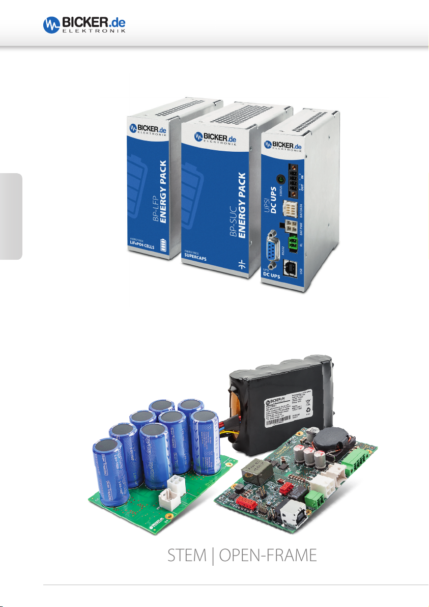
UPSI-SYSTEM | DIN-RAIL
UPSI-SYSTEM | OPEN-FRAME
2

UPSI-1208(D) | UPSI-2406(D)
1 Produkt- und Funktionsbeschreibung ...........................................4
2 Vor Inbetriebnahme lesen! ...............................................................4
3 Bestimmungsgemäße Verwendung – Beschreibung ..................5
4 Einbau – Installationshinweise .........................................................5
5 Konvektion und Einbaulage .............................................................6
6 Technische Zeichnung – Anschlüsse – Kommunikation .............7
7 Anschlussbeschreibung X1 bis X11 ................................................8
8 Dimensionierung der vorgeschalteten Stromversorgung ...... 12
9 Inbetriebnahme ............................................................................... 13
10 Anschlussplan UPSI-1208 / UPSI-2406 ......................................... 14
11 Anschlussplan UPSI-1208D / UPSI-2406D ................................... 15
12 Sicherheitsmaßnahmen beim Betrieb des USV-Systems......... 16
13 Ladezeit .............................................................................................. 17
14 Verpolung / Überlast / Kurzschluss .............................................. 17
15 Überbrückungszeiten ..................................................................... 17
16 Verhalten bei Überschreiten der maximalen Pufferzeiten ...... 17
17 Batteriestart ...................................................................................... 18
18 Bestelldaten der vorgesehenen Speichermedien ..................... 18
19 Status LED.......................................................................................... 19
20 Software ............................................................................................. 20
21 Kommunikationsprotokoll RS232 ................................................ 24
22 Befehlsliste ........................................................................................ 25
23 Empfehlungen für eine lange Lebensdauer des USV-Systems 34
24 Wartung ............................................................................................. 35
25 Entsorgung ........................................................................................ 35
26 Haftungsausschluss ......................................................................... 35
Deutsch
3
UPSI-1208(D) | UPSI-2406(D)
Herzlichen Glückwunsch zu Ihrem neuen Qualitätsprodukt!
Dieses Handbuch soll den Anwender mit dem Produkt samt dessen Komponenten und
Eigenschaften vertraut machen und möglichst vollständige und genaue Informationen
dazu liefern. Für mögliche vorhandene Fehler kann Bicker Elektronik jedoch keine Haftung
übernehmen. Hinweise hierzu, Verbesserungsvorschläge und Kritik werden jederzeit sehr
gerne entgegengenommen.
1 Produkt- und Funktionsbeschreibung
UPSI-1208(D) und UPSI-2406(D)
Deutsch
Die UPSI-1208(D) / UPSI-2406(D) (nachfolgend USV) sind DC/DC-USV-Systeme mit zahlreichen digitalen Features und einer hohen Performance. Die USV kann mit unterschiedlichen Speichermedien (nachfolgend auch Batteriepacks, Akkus etc.), unterschiedlicher
Kapazität und unterschiedlicher Chemie betrieben werden. Es dürfen ausschließlich
Batteriepacks von Bicker Elektronik verwendet werden, da die Ladeeinstellungen
nach Erkennung des Batteriepacks erfolgen. Die elektrischen und technischen Daten sind
dem Datenblatt zu entnehmen.
2 Vor Inbetriebnahme lesen
Dieses Handbuch sowie sämtliche Datenblätter, Sicherheitsanweisungen usw. sind vor
Installation und Benutzung genauestens zu lesen und einzuhalten. Ist dies nicht der Fall,
können in bestimmten Situationen Garantie und Gewährleistung teilweise oder ganz
entfallen.
Vorsicht bei der Handhabung!
Auch nach dem Trennen der Versorgung und wenn am Ausgang keine
Spannung messbar ist, wird die USV weiterhin über das Speichermedium
mit Energie versorgt.
Achtung Kurzschlussgefahr!
Die USV niemals auf leitende Flächen legen. Kurzschlussgefahr!
4
UPSI-1208(D) | UPSI-2406(D)
3 Bestimmungsgemäße Verwendung – Beschreibung
Dieses Gerät ist für den Einbau in ein Gehäuse ausgelegt (gilt nicht für UPSI-1208D /
UPSI-2406D). Es sind geeignete Gehäuse zu verwenden, die es gegen mechanische,
elektrische und Feuergefahr schützen. Das Gerät ist für den professionellen Einsatz
in Bereichen wie industrieller Steuerungs-, Büro-, Kommunikations- und Messtechnik
gedacht. Es darf nicht in Vorrichtungen oder Anlagen verwendet werden, bei denen eine
Fehlfunktion zu schweren Verletzungen führt oder Menschenleben gefährdet.
Die funktionelle Verwendung der USV besteht in der Überbrückung von kurzzeitigen und
langanhaltenden Spannungsausfällen und/oder -schwankungen. Das Gerät kann aber
auch für durch den Anwender initiierte Abschaltungen der Versorgungsspannung oder
Zyklen eingesetzt werden, wie z. B. das Tauschen größerer Akkus bei Fahrzeugen, wobei
die Elektronik weiterhin versorgt werden soll, Öffnen und Schließen von Sicherheitsventilen
nach einer Fehlfunktion oder das Herunterfahren eines Systems. Als Speichermedium
dienen hierbei jeweils Superkondensatoren (auch Ultrakondensatoren oder EDLC
genannt) und Li-Ionen Batteriepacks mit LiFePO4-Technologie.
Eine wichtige Eigenschaft ist, dass die Ausgangsspannung im Backup-Betrieb stets geregelt wird und nicht mit abfallender Spannung der Akkus sinkt. Zur Verlängerung der
Lebensdauer werden die Akkupacks durch optimierte Ladealgorithmen schnell geladen.
4 Einbau – Installationshinweise
Dieses Gerät darf nur von Fachpersonal installiert und in Betrieb genommen
werden! Die USV ist ein Einbauteil, welches vorzugsweise in einem Metallgehäuse
verwendet werden sollte (gilt nicht für UPSI-1208D/UPSI-2406D). Das Endgerät muss
die aktuellen EMV-Normen sowie die einschlägigen Normen zur elektrischen Sicherheit
einhalten. Die Applikation sowie die Platine müssen beim Einbau stromlos sein. Die
Leitungen müssen fest angeschlossen sein und dürfen über keine scharfen Kanten
geführt werden. Auf richtige Polarität muss geachtet werden!
Deutsch
Achtung Verbrennungsgefahr!
Das Gerät darf nicht im eingeschalteten Zustand oder unmittelbar nach dem Ausschalten berührt werden. Heiße Oberflächen
können zu Verbrennungen führen.
5
UPSI-1208(D) | UPSI-2406(D)
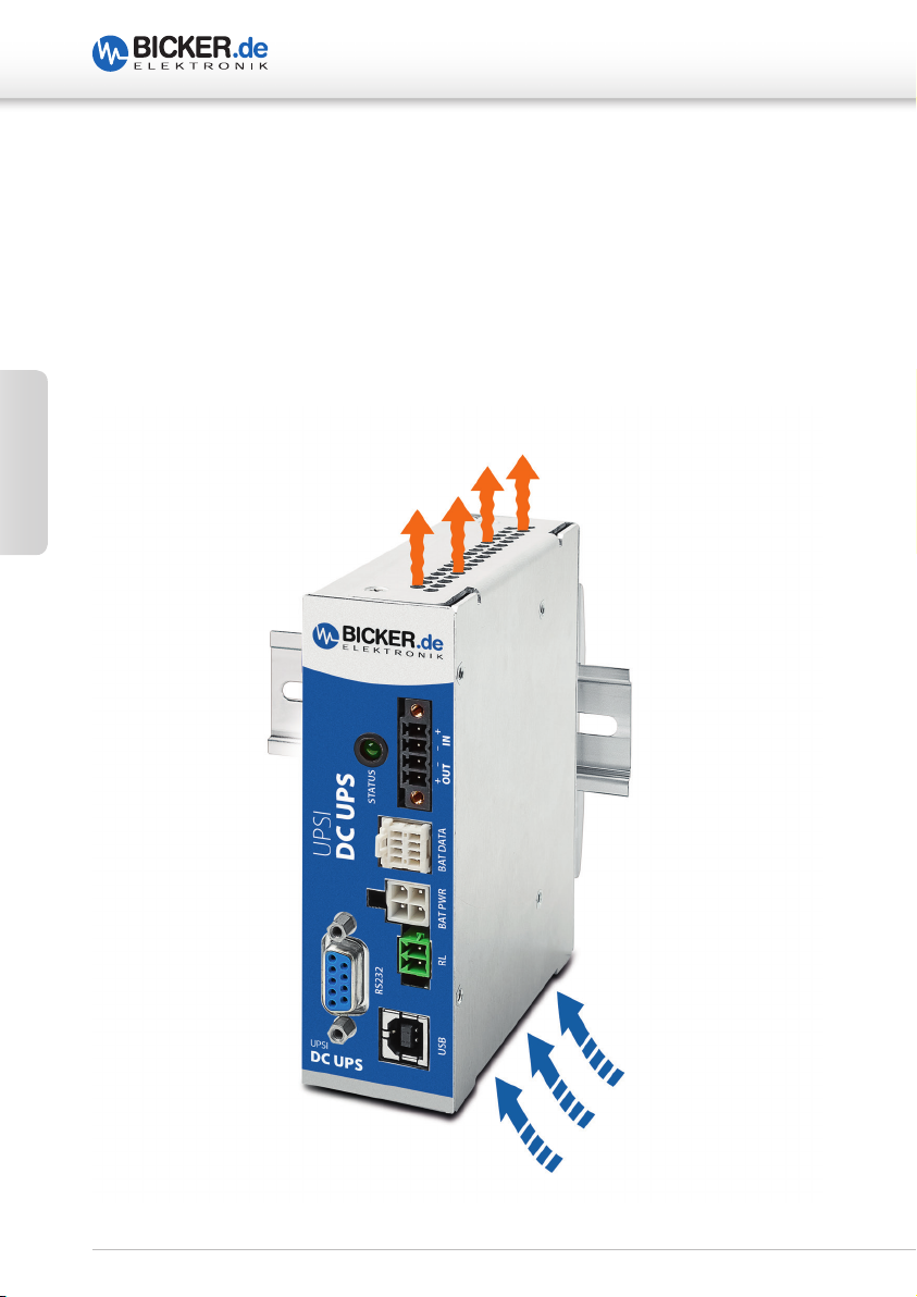
5 Konvektion und Einbaulage
Ausreichende Belüftung sowie freie Luftzirkulation müssen beim Einbau sichergestellt
sein. Es sollten keine Lüftungslöcher durch andere, benachbarte Komponenten verdeckt
sein. Bei den DIN-Rail-Versionen ist eine senkrechte Montage auf eine waagerechte
Schiene (Hutschienen nach EN 60715) empfehlenswert, um die bestmögliche Konvektion
der USV zu erreichen. Eine andere Einbaulage ist möglich, ein Betrieb bis +70 °C
Umgebungstemperatur kann dadurch aber nicht mehr gewährleistet werden.
Deutsch
6
UPSI-1208(D) | UPSI-2406(D)
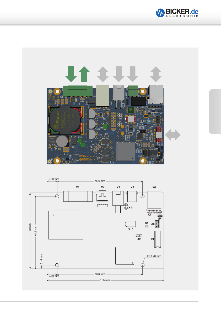
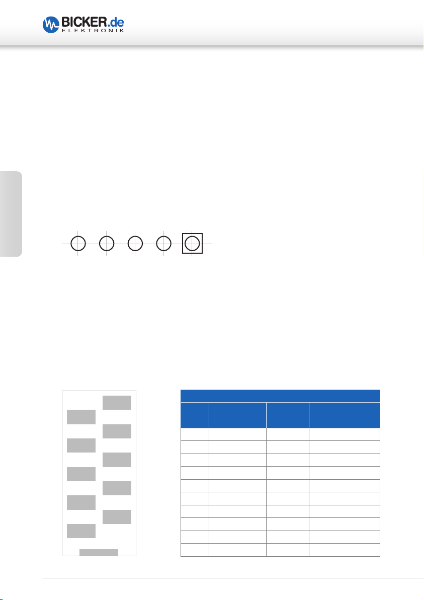
68 mm
3.14 mm
9.30 mm
105 mm
76.6 mm
X11
1
1
X2
X1 X4 X3 X5 X6
4x 3.20 mm
X9
X8
S1
JP1
X7
X10
9.30 mm
76.6 mm
64.9 mm
6 Technische Zeichnung – Anschlüsse – Kommunikation
Battery
Pack
VinV
out
I2C
Power
Relais Data
Deutsch
Data
Abb. 1
Abb. 2
7
7 Anschlussbeschreibung X1 bis X11 (Abb. 2)
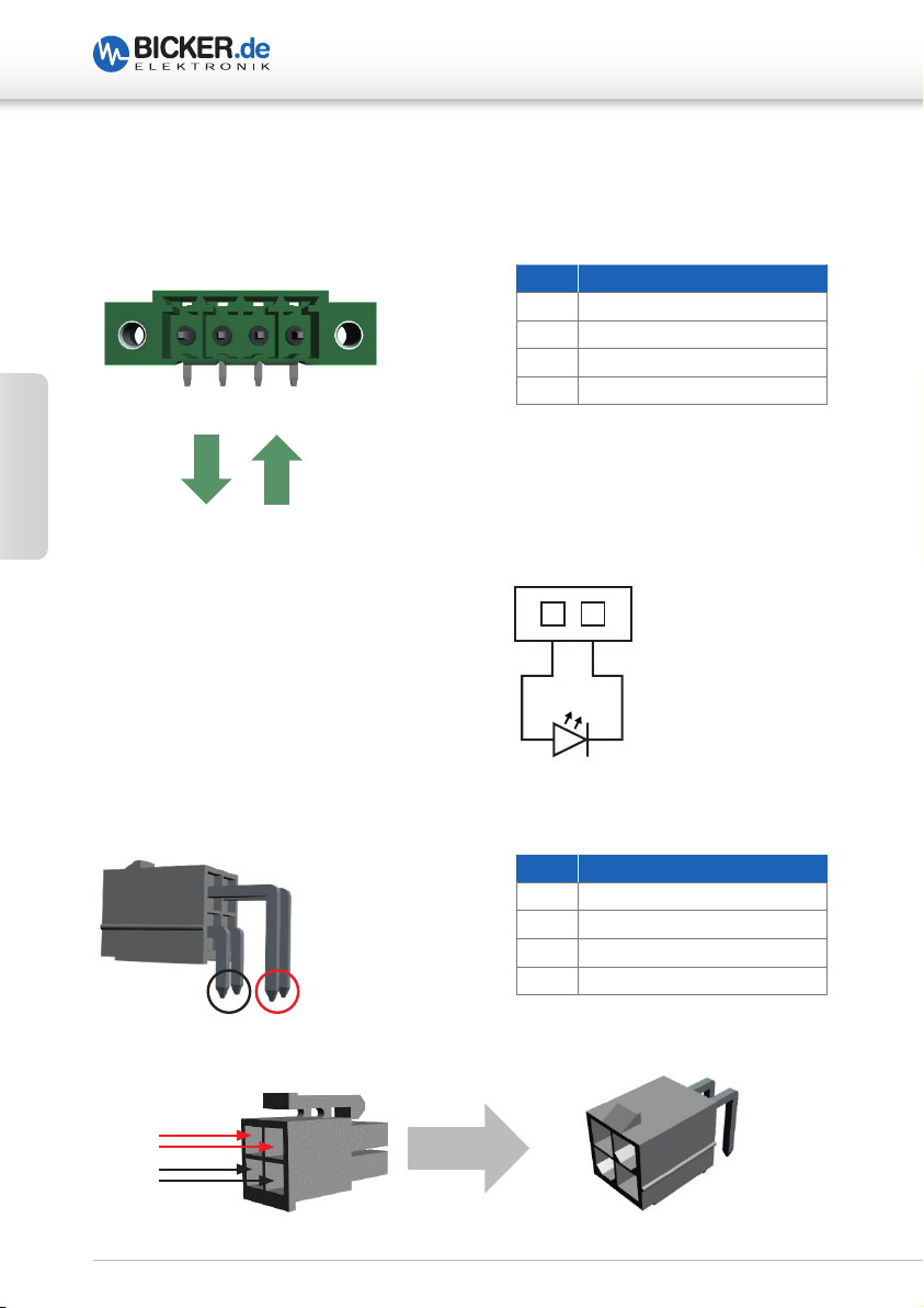
X1 EINGANG & AUSGANG
UPSI-1208(D) | UPSI-2406(D)
Deutsch
X2
X3
X1-4 X1-3 X1-2 X1-1
++––– +
V
out
PIN HEADER FÜR LEDANSCHLUSS
BATTERIEANSCHLUSS
V
in
PIN X1
1 Vin +
2 Vin –
3 Vout –
4 Vout +
1
+ –
PIN X3
1 Batterie –
2 Batterie –
3 Batterie +
4 Batterie +
Low-Power LED
max. 10 mA
X3-1 X3-2 X3-3 X3-4
V+
V–
8
Zu
X3 / UPSI
UPSI-1208(D) | UPSI-2406(D)
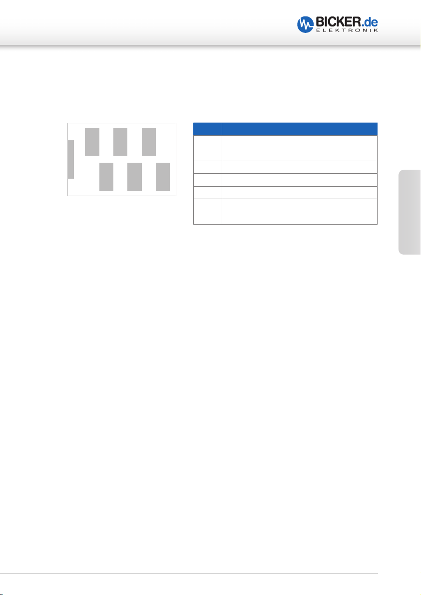
7 Anschlussbeschreibung X1 bis X11 (Abb. 2)
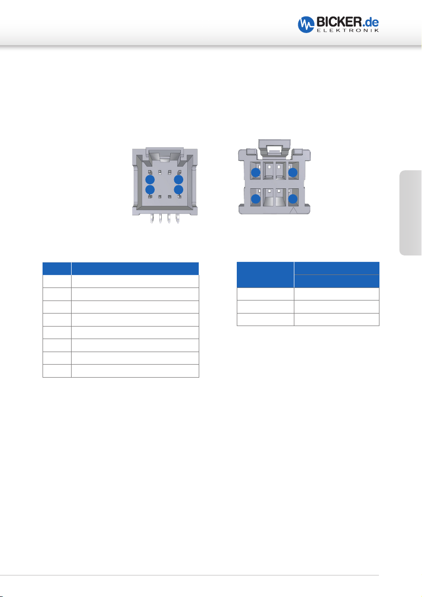
X4 BATTERIEDATENANSCHLUSS
PLATINENBUCHSE BATTERIESTECKER
8
7
PIN FUNKTION
1 GPIO / I²C
2 I²C_0-SCL (Clock I²C Kanal 0)
3 Select 2
4 I²C_0-SDA (Data I²C Kanal 0)
5 Select 1
6 SP0 (Batterie Present Kanal 0)
7 +5V (max. 50 mA)
8 GND
2
1
8
7
BATTERIE
TYP
2
Deutsch
1
X4
GENUTZTE PINS
Li-Ion 2, 4, 6, 8
Li-Ion Parallel 1, 2, 3, 4, 5, 6, 8
Supercap 2, 4, 6, 8, 7
9
UPSI-1208(D) | UPSI-2406(D)
7 Anschlussbeschreibung X1 bis X11 (Abb. 2)
X5 RELAISANSCHLUSS
Schließerkontakt: Bei Netzunterbrechung ist Schalter geschlossen (= 0 Ω ).
X6
USBANSCHLUSS
USB Buchse Typ B
X7 USB PIN HEADER 2.54 MM
Deutsch
X8
X9
1
+5V USB – USB + GND GND
JTAG
RS232
PIN 10
PIN 9
PIN 8
PIN 7
PIN 6
PIN 5
PIN 4
PIN 3
PIN 2
PIN 1
X9
PIN SIGNAL
UPSI
DSUB9 SIGNAL
MAINBOARD
1 NC 1 NC
2 DTR 6 DSR
3 TXD 2 RXD
4 NC 7 NC
5 RXD 3 TXD
6 NC 8 NC
7 DSR 4 DTR
8 NC 9 NC
9 GND 5 GND
10 NC
10
UPSI-1208(D) | UPSI-2406(D)
7 Anschlussbeschreibung X1 bis X11 (Abb. 2)
X10 ERWEITERTE FUNKTION
PIN X10
PIN 1
PIN 3
PIN 5
PIN 2
PIN 4
Pin 1-5 in Abklärung mit
Bicker Elektronik GmbH
X11
BATTERIESTART
PIN 6
1 XPF#
2 GPIO / I²C
3 GND
4 GPIO / I²C
5 5 V DC Versorgung (max. 50 mA)
6 ANLG-R Eingang,
Alternativer Power Fail Timer / 30 V max
Pin Header 2.54 mm für Batteriestartfunktion:
Wenn Anschlüsse >2 s kurzgeschlossen werden, startet das Gerät aus der Batterie
heraus, ohne dass eine Eingangsspannung benötigt wird.
Deutsch
11
UPSI-1208(D) | UPSI-2406(D)
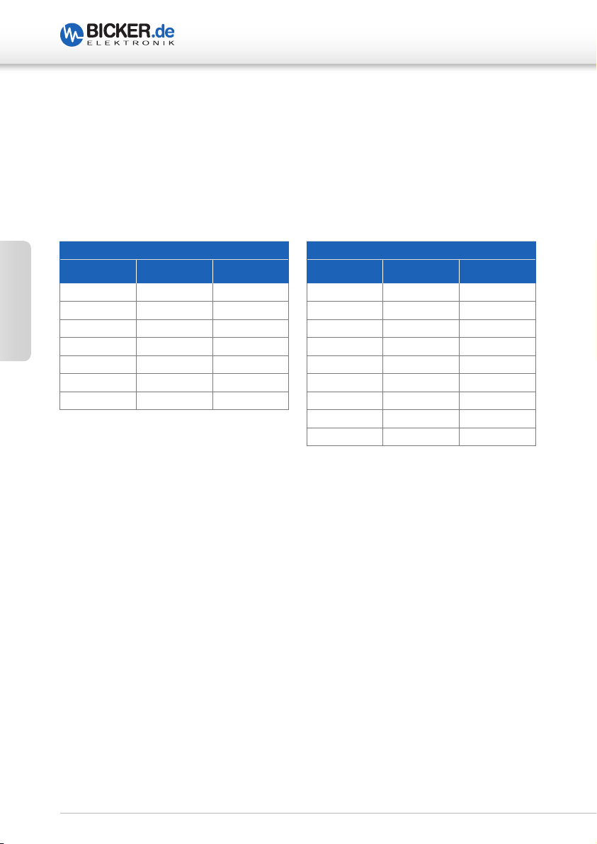
8 Dimensionierung der vorgeschalteten Stromversorgung
Es ist darauf zu achten, dass die Quelle korrekt dimensioniert ist und genug Strom liefert,
um den Ladevorgang und die Funktion der Applikation zu garantieren. Die UPSI reduziert je nach Last den Ladestrom. Es muss jedoch dafür gesorgt werden, dass auch bei
Maximallast geladen wird. Daraus ergeben sich folgende Mindestanforderungen an die
Quelle in Abhängigkeit von der Last:
Deutsch
UPSI-2406 (D)
I
LOAD
[A] I
CHARGE
[A] I
0 3 3
1 3 4
2 2,7 4,7
3 2,5 5,5
4 2,2 6,2
5 2 7
6 1,5 7,5
IN-MIN
[A]
UPSI-1208 (D)
I
LOAD
[A] I
CHARGE
[A] I
0 4 4
1 5 5
2 3,6 5,6
3 3,2 6,2
4 3 7
5 2,5 7,5
6 2,2 8,2
7 1,8 8,8
8 1,5 9,5
IN-MIN
[A]
12
UPSI-1208(D) | UPSI-2406(D)
9 Inbetriebnahme
Es muss sichergestellt sein, dass die USV und das Speichermedium ordnungsgemäß verbaut sind. Das Speichermedium kann unter Einhaltung der Anschlussreihenfolge (siehe
Seite 12/13) jederzeit abgesteckt und getauscht werden. Zwei Verbindungen sind zu
beachten: Eine für Daten (X4) und eine für Leistungsführung (X3). Der Start kann nach
dem Anschließen eines geladenen Batteriepacks auf zwei Wegen erfolgen:
1. Start aus dem Batteriepack in den Backup-Betrieb: Durch das Kurzschließen von
X11 für länger als 2 s. Hierzu kann auch ein Taster verwendet werden.
oder
2. Durch das Anschließen der Versorgungsspannung: Wird an den Eingangs-
klemmen eine Spannung größer als 11,5 V für die UPSI-1208 (D) und größer als 22,5 V für
die UPSI-2406 (D) angeschlossen, wird der Batteriepack abgefragt und übermittelt seine
Daten. Die USV stellt die entsprechende Ladeschlussspannung ein und gibt den Pack
über das System Present (X11) frei. Erst danach wird auch der Lader freigegeben und das
Laden des Akkus beginnt. Der Vorgang geschieht innerhalb weniger Millisekunden.
Deutsch
Nur Original-Batteriepacks von Bicker Elektronik verwenden!
Es dürfen nur Batteriepacks von Bicker Elektronik eingesetzt werden.
Diese sind entsprechend qualifiziert und verfügen über die notwendigen Schutzfunktionen. Darüber hinaus erfolgt die Einstellung der
Ladecharakteristik anhand einer Kodierung.
Die angelegte Spannung am Eingang wird, verringert durch einen stromabhängigen
Spannungsabfall, an den Ausgang weitergeleitet (Vout = Vin - 0,3 V bei Maximalstrom).
Das Gerät lädt den Energiespeicher und überwacht die Spannungsschwellen am Eingang
(USV-Funktion).
Es ist darauf zu achten, dass die Quelle genug Strom liefert, um den Ladevorgang zu
garantieren (siehe auch Seite 12, Abschnitt 8 Dimensionierung der vorgeschalteten
Stromversorgung).
13
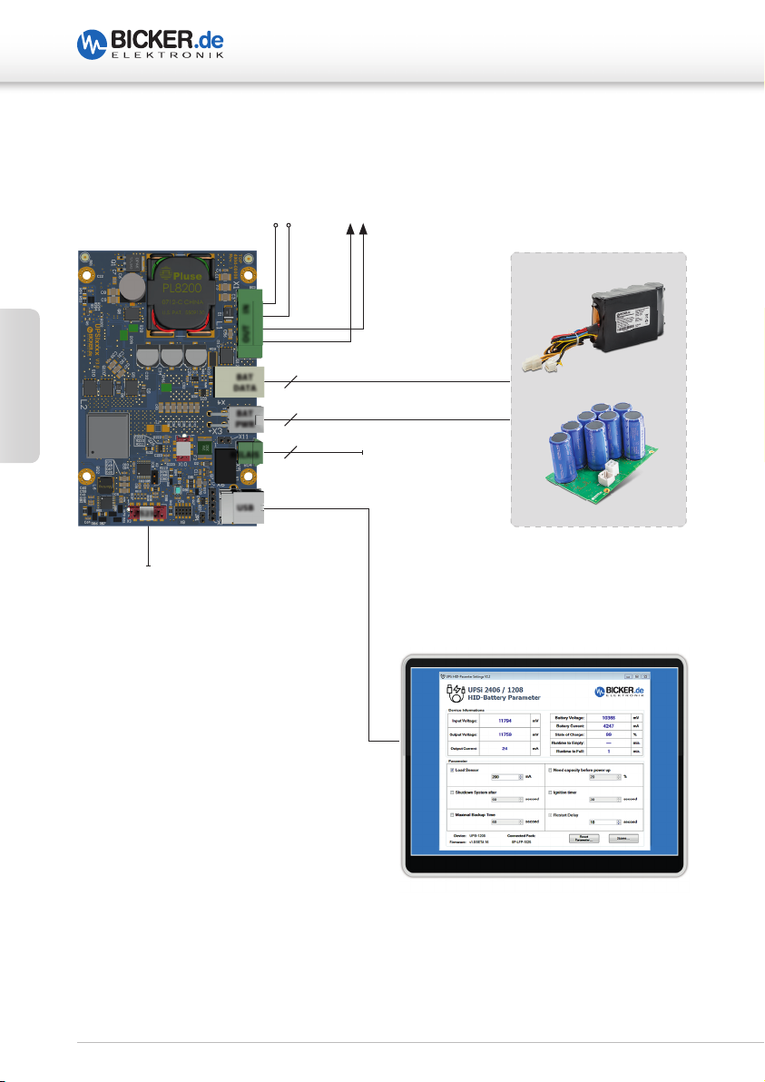
10 Anschlussplan UPSI-1208 / UPSI-2406
APPLIKATION
V
IN
+ +– –
+ – – +
OUT IN
4 (LiFePO4) oder 5 (EDLC) BAT DATA
BAT
DATA
4 BAT PWR
Deutsch
RS232
RS232 für individuelle Verwendung
BAT
PWR
RELAIS
USB
2 RELAIS
USB
UPSI-1208(D) | UPSI-2406(D)
ENERGIESPEICHER
BP-LFP (LiFePO4)
ODER
BP-SUC (EDLC)
ANSCHLUSSREIHENFOLGE
1. BAT DATA
2. BAT PWR
3. APPLIKATION
4. V
IN
5. RELAIS / USB / RS232
BITTE BEACHTEN!
Die korrekte Anschlussreihenfolge muss genau befolgt werden. Wenn Sie den
Energiespeicher wechseln, während das System läuft (Hot-Swapping), müssen zwischen
dem Trennen und dem erneuten Anschließen mindestens 6 Sekunden verstreichen.
14
UPSI-1208(D) | UPSI-2406(D)
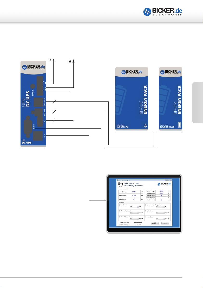
11 Anschlussplan UPSI-1208D / UPSI-2406D
APPLIKATION
V
IN
+ +– –
4 (LiFePO4) oder 5 (EDLC) BAT DATA
4 BAT PWR
2 RELAIS
ENERGIESPEICHER
Deutsch
ODER
RS232
USB
für individuelle Verwendung
ANSCHLUSSREIHENFOLGE
1. BAT DATA
2. BAT PWR
3. APPLIKATION
4. V
IN
5. RELAIS / USB / RS232
BITTE BEACHTEN!
Die korrekte Anschlussreihenfolge muss genau befolgt werden. Wenn Sie den
Energiespeicher wechseln, während das System läuft (Hot-Swapping), müssen zwischen
dem Trennen und dem erneuten Anschließen mindestens 6 Sekunden verstreichen.
15
UPSI-1208(D) | UPSI-2406(D)
12 Sicherheitsmaßnahmen beim Betrieb des USV-Systems
Der Spannungsabfall der Zuleitung ist zu beachten! Der maximale Ladestrom kann bei zu
langen Leitungen zu hohen Spannungsabfällen führen. Ist der Spannungsabfall zu hoch,
kann es zu einer Unterschreitung des Schwellwertes kommen und ein unbeabsichtigter
Power Fail ausgelöst werden. Die Spannung bei maximaler Last direkt am Eingang des
Gerätes darf 11,5 V (UPSI-1208(D)) bzw. 22,5 V (UPSI-2406(D)) nicht unterschreiten.
Auch nach dem Trennen der Versorgung läuft das Gerät für einige Zeit nach
Unterschreitung des Lastsensors weiter (Einstellung eines Schwellwerts für den
Lastsensor: Ströme unter diesem Wert werden als „keine Last“ gewertet und die USV
nach eingestellter Zeit abgeschaltet).
Deutsch
Ein Kurzschluss direkt am Ausgang des Geräts kann zur Schädigung oder Zerstörung führen. Erst ab einer bestimmten Impedanz (L > 50 nH, R > 50 mΩ) kann ein Schutz gewährleistet werden.
Warnung!
Missachtung nachfolgender Punkte kann einen elektrischen Schlag,
Brände, schwere Unfälle oder Tod zur Folge haben.
1. Die Eingangsspannung muss vor Installations-, Wartungs-
oder Änderungsarbeiten am Gesamtsystem abgeschaltet
und gegen unbeabsichtigtes Wiedereinschalten gesichert
werden.
2. Auf eine ordnungsgemäße und fachgerechte Verdrahtung
muss geachtet werden.
3. Änderungen oder Reparaturversuche am Gerät sind zu
unterlassen.
4. Die Einwirkung von Fremdkörpern, wie z.B. Metallteilen,
auf das Gerät ist zu vermeiden.
5. Das Gerät darf nicht in feuchter Umgebung oder in einer
Umgebung, bei der mit Betauung oder Kondensation zu
rechnen ist, betrieben werden.
16

UPSI-1208(D) | UPSI-2406(D)
13 Ladezeit
Die Ladezeiten sind abhängig vom Energiespeicher, der Eingangsspannung und dem
Laststrom.
14 Verpolung / Überlast / Kurzschluss
Das Gerät ist gegen Verpolung bei Inbetriebnahme (Gerät aus, nicht aktiv) geschützt.
Befindet sich das Gerät im Batterie-Start-Modus oder im laufenden Backup-Betrieb,
ist kein Verpolschutz gegeben. Im Falle eines zu hohen Stromes (ca. 130-160 % des
Nominalwerts) schaltet das Gerät ab und läuft automatisch weiter, sobald sich der
Ausgangsstrom wieder im spezifizierten Bereich befindet bzw. die Überlast nicht mehr
anliegt. Ein Startversuch erfolgt jede Sekunde (non-Latch, timer 1s). Die Auswirkungen
eines Kurzschlusses auf das Gerät sind abhängig von der Leitungslänge / Querschnitt
(Impedanz) der Ausgangsverdrahtung. Bei einem Kurzschluss direkt an den Klemmen
kann es zu einer Beschädigung des Gerätes kommen.
15 Überbrückungszeiten
Die USV ist mit unterschiedlichen Speichertechnologien kombinierbar. Die nominalen
Überbrückungszeiten können den Datenblättern entnommen werden.
Die Batteriepacks weisen unterschiedliche Eigenschaften auf, ein wichtiger Aspekt davon
ist die Umgebungstemperatur. Bei extrem niedrigen oder hohen Temperaturen kann es
zu einer Minderung der nominalen Überbrückungszeit kommen.
Deutsch
16 Verhalten bei Überschreiten der maximalen Pufferzeiten
Beim Überschreiten der gegebenen Überbrückungszeiten wird der Ausgang anhand der
Entladespannung des entsprechenden Speichers getrennt (Tiefentladeschutz).
Bei den Superkondensatoren, die nicht empfindlich auf eine Tiefentladung reagieren, wurde eine Schwelle festgelegt, die durch den Strom begrenzt wird. Je niedriger die Spannung, desto höher der Strom an den Kondensatoren bei konstanter
Ausgangsleistung.
Wenn über 70 % des maximal zulässigen Ausgangsstroms während des Entladens der
Superkondensatoren gezogen wird, schaltet der Wandler zunächst ab, ohne den Ausgang
sofort zu trennen und eine niedrigere Spannung erscheint am Ausgang (Zustand <2s).
Dieser Zustand sollte vermieden werden, indem das System rechtzeitig heruntergefahren
wird, bevor die Superkondensatoren unter hohen Strömen entladen werden.
17

UPSI-1208(D) | UPSI-2406(D)
17 Batteriestart
Diese Funktion ermöglicht das Starten der Applikation oder des Geräts aus der Batterie
heraus, ohne dass die Spannungsversorgung vorhanden oder angeschlossen ist. Um
diese zu aktivieren muss der Pin Header X11 (siehe Seite 7, Abb. 2) für länger als 2s überbrückt werden.
18 Bestelldaten der vorgesehenen Speichermedien
UPSI-1208 (D)*
Artikel Kerndaten
Deutsch
BP-LFP-1025 (D)* LiFePO4, 1p3s, 25Wh, 2.5Ah, 9.9Vnom
BP-SUC-1011 (D)* Supercap, 1p4s, 10,4 Vnom, 1.8 kJ (useful 1.1 kJ)
BP-SUC-1020 (D)* Supercap, 2p4s, 10,4 Vnom, 3.6 kJ (useful 2 kJ)
UPSI-2406 (D)*
Artikel Kerndaten
BP-LFP-1325 (D)* LiFePO4, 1p4s, 33Wh, 2,5Ah, 13.2Vnom
BP-SUC-1615 (D)* Supercap, 1p6s, 15,6 Vnom, 2.7 kJ (useful 1.5 kJ)
BP-SUC-2120 (D)* Supercap, 1p8s, 20,8 Vnom, 3.6 kJ (useful 2 kJ)
*(D) für DIN-Rail
Detaillierte Informationen zu den aufgeführten Speichermedien sind den zugehörigen
Datenblättern zu den USV-Modellen sowie den Speichermedien zu entnehmen.
18

UPSI-1208(D) | UPSI-2406(D)
19 Status LED
1 x blinken, Pause 1,5s Status: Batteriestart
2 x blinken, Pause 1,5s Status: Es wird Kapazität zum Starten benötigt,
Zustand Laden
3 x blinken, Pause 1,5s Status Herunterfahren: Warten bis System herunter-
gefahren ist
4 x blinken, Pause 1,5s Status Neustart: Ausgang ist abgeschaltet und Zeit
läuft bis Neustart (Rebootphase)
5 x blinken, Pause 1,5s Status: Keine Batterie erkannt
1 Hz Blinken Netzausfall Status: Batteriebetrieb
Deutsch
Dauer An Status: System OK
Schnelles Blinken Status: Ausgangsspannung zu gering
USV wird abgeschaltet
19

UPSI-1208(D) | UPSI-2406(D)
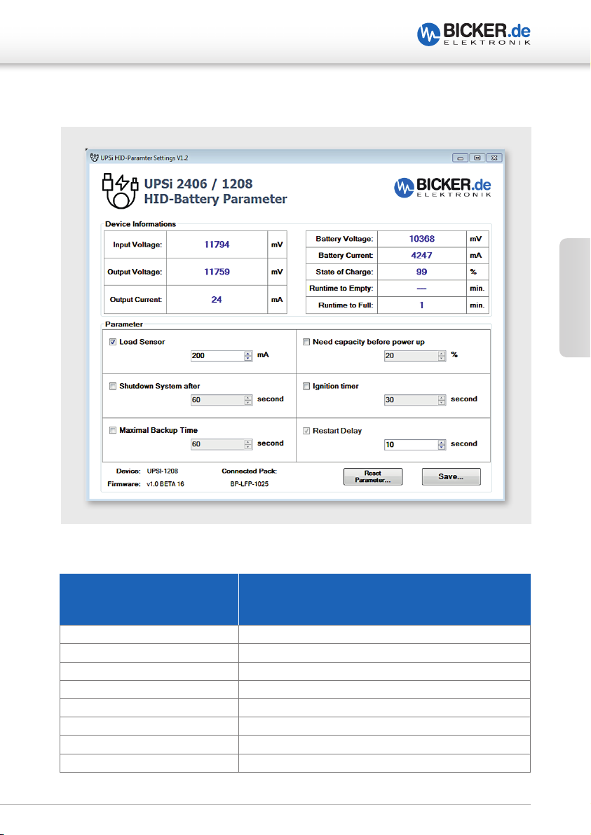
20 Software
Die USV wird als „Human-Interface-Device“ (HID-Batterie, HID-VCom) unter Windows
erkannt, wenn diese über USB angeschlossen wird. Als HID-Batterie wird für das
Herunterfahren des Betriebssystems keine zusätzliche Software benötigt und kann
dadurch mit den internen Akku-Einstellungen des Betriebssystems gesteuert werden.
Falls ein Herunterfahren nach Zeit gewünscht ist, kann mit der Software „UPSI HID-Battery
Parameter Settings“ die Funktion aktiviert und die gewünschte Überbrückungszeit
eingestellt werden. Das Herunterfahren des Betriebssystems steuert komplett die UPSI
Hardware, die Software kann nach einstellen der Parameter geschlossen bleiben.
Des Weiteren besitzt die UPSI über USB einen sogenannten virtuellen Com-Port und eine
physikalische RS232 (light) Schnittstelle, über die weitere Daten ausgelesen werden kön-
Deutsch
nen. Eine Beschreibung des Kommunikationsprotokolls finden Sie ab Seite 24.
Hinweis:
Wenn im System andere Akku- oder Powersysteme (ACPI / USB) verwendet werden,
kann es zu Konflikten kommen. Diese Geräte sollten deaktiviert werden, was durchaus
nur mit einem BIOS-Update erreicht werden kann, um die vorhandene Akkufunktion zu
entfernen.
20
UPSI-1208(D) | UPSI-2406(D)
20 Software
Deutsch
Device Information
Beschreibung
Anzeige –
keine Einstellungen möglich
Input Voltage Eingangsspannung – wird nur im Normalbetrieb angezeigt
Output Voltage Ausgangsspannung – wird immer angezeigt
Output Current Strom der Applikation
Battery Voltage Spannung am Akkupack
Battery Current Strom am Akkupack
State of Charge Akku-Ladezustand
Runtime to Empty Restlaufzeit unter aktuellen Lastbedingungen
Runtime to Full Ladezeit bis 100 % geladen
21

20 Software
UPSI-1208(D) | UPSI-2406(D)
Parameter
einstellbar
Load Sensor 100mA…800mA
Shutdown
System after
Deutsch
Maximum
Backup Time
Need capacity
before power up
Ignition Timer 1s…3600s
Wertebereich/
Einheit
in mA-schritten
1s…3600s
in s-schritten
1s…3600s
in s-schritten
1%...100%
in 1%-schritten
in s-schritten
Beschreibung
Stromwert, dessen Unterschreitung zur Annahme führt,
dass das zu versorgende System aus ist. Das System wird
daraufhin für x Sekunden (Restart Delay) getrennt, um die
Neustart-Funktion durchzuführen, falls die Eingangsspannung zurückgekehrt ist.
Betrifft die Überbrückungszeit: Während dieser Zeit wird die
Versorgung des Systems aufrecht erhalten. Nach Ablauf dieser Zeit und weiterhin fehlender Eingangsversorgung wird
der Shutdown-Prozess am PC initiiert. Wenn innerhalb dieser Zeit die Spannung netzseitig am Eingang wiederkehrt,
wird nichts unternommen.
Die maximale Überbrückungszeit. Nach dieser Zeit wird das
System getrennt. Diese Einstellung kann eingesetzt werden
für Systeme, die keinen Herunterfahrprozess benötigen
oder für den Fall, dass das System sich aufhängt und hart
getrennt werden muss.
Mindestkapazität für die Freigabe der USV. Hiermit kann sichergestellt werden, dass die Applikation bei einem Ausfall
sicher versorgt werden kann. Die Einschaltzeit kann sich
hierdurch verzögern.
Hier wird ein zweites Signal (X10 Pin 6=V+ auf Pin3=GND)
ausgewertet. Ist dieses high (>3,8 V, 29 V max), wird statt
der Shutdown Zeit diese Zeit verwendet, um das System
herunterzufahren. Diese Einstellung kann verwendet
werden, um eine alternative Verweildauer gegenüber der
Einstellung "Shutdown System After" einzustellen. Wenn
nun ein „high Signal“ anliegt, wird die Zeit in „Shutdown
System after“ ignoriert und stattdessen die „Ignition Timer“
Dauer herangezogen, um den Herunterfahrprozess zu
verzögern.
Restart Delay 1s…180s
22
in s-schritten
Zeitverzögerung nach Trennen des Systems für die er neute
Freigabe der Versorgung. Wenn während des Herunterfahrens oder danach die Versorgung nach einem Ausfall
wiederkehrt, wird das System über die Ausgangsspannung
der USV erneut gestartet.

UPSI-1208(D) | UPSI-2406(D)
20 Software
Software-Parameter-Impulsdiagramm
NORMAL
V
IN
V
OUT
POWER
FAIL
SHUTDOWN
SYSTEM AFTER
APPLICATION CURRENT IS
BELOW LOAD SENSOR
SHUTDOWN
PROCESS
RESTART
DELAY
Zurücksetzen der Parameter
Mit „Reset Parameter…“ werden die Einstellungen auf die Standardwerte zurückgesetzt.
Speichern der Parameter
Mit „Save…“ werden die Einstellungen auf der USV gespeichert. Die Software kann dann
geschlossen werden.
Deutsch
23

UPSI-1208(D) | UPSI-2406(D)
Transfer Packet
Data Packet
Header
D A T A
Byte 0
Byte 1
Byte 2
Byte 3
Byte 4 to 254 (can be null)
Last Byte
Size of
Packet
=
‘Size of
used Data’
21 Kommunikationsprotokoll RS232
Transfer Packet - Beschreibung
Die Beschreibung des Protokolls bezieht sich auf die serielle Schnittstelle RS232. Das
Protokoll gilt zugleich für gesendete und empfangene Daten.
Control
Byte
Data
Deutsch
(0x01)
ASCII
‘SOH’
Header’ +
‘Size of
Command
Index
Command
from List
Transfer or Received Data
Beschreibung
Der Datentransfer beginnt immer mit einem Startzeichen (0x01) und endet mit einem
Schlusszeichen (0x04). Nach dem Senden des Startsignals folgt der “Header” mit einer
Größe von 3 Byte. Der Header beinhaltet Informationen über die Größe des Datenpakets,
den Befehlsindex und die Befehls ID. Nach Übermittlung des Datenpakets wird die
Übertragung mit dem Schlusszeichen (0x04) beendet.
Verbindungsdaten RS232
Baudrate 38400
Data length 8-bit
Stop bit 1
Parity disabled
Control
Byte
ASCII ‘EOT’
(0x04)
24
Verbindungsdaten CDC VCOM
Baudrate Nicht relevant
Data length 8-bit
Stop bit 1
Parity disabled

UPSI-1208(D) | UPSI-2406(D)
22 Befehlsliste
Command Index
INDEX NO. Description
1 Generic
2 Sensors
3 Charge Controller
4 Battery A
5 Battery B
7 Parameter
22.1 Command Index “Generic” 0x01
GetDeviceName() 0x62
This read function returns the device name as string.
Cmd Name Access Type Min. Max Unit
0x62 GetDeviceName() R char[ ] - - -
Transfer packet: 0x01 0x03 0x01 0x62 0x04
Deutsch
GetFirmwareVersion() 0x63
This read function returns the firmware version as string.
Cmd Name Access Type Min. Max Unit
0x63 GetFirmwareVersion() R char[ ] - - -
Transfer packet: 0x01 0x03 0x01 0x63 0x04
GetConnectedEnergyPack() 0x64
This read function returns the connected energy storage pack as string (P/N).
Cmd Name Access Type Min. Max Unit
0x64 GetConnectedEnergyPack() R char[16] - - -
Transfer packet: 0x01 0x03 0x01 0x64 0x04
25

22.2 Command Index “Sensors” 0x02
GetCPUTemperature() 0x00
This read function returns the cpu temperature.
Cmd Name Access Type Min. Max Unit
0x00 GetCPUTemperature() R Uint16 0 +150 °C
Transfer packet: 0x01 0x03 0x02 0x00 0x04
GetOutputCurrent() 0x01
This read function returns the output current.
Cmd Name Access Type Min. Max Unit
Deutsch
0x01 GetOutputCurrent () R Int16 0 +32768 mA
Transfer packet: 0x01 0x03 0x02 0x01 0x04
GetInputVoltage() 0x02 (not connected at moment)
This read function returns the input voltage.
Cmd Name Access Type Min. Max Unit
0x02 GetInputVoltage () R Int16 0 +32768 mV
Transfer packet: 0x01 0x03 0x02 0x02 0x04
UPSI-1208(D) | UPSI-2406(D)
22.3 Command Index “Charge Controller” 0x03
GetEnergyStorageVoltage() 0x20
This read-word function returns the measured voltage of the capacitor 1.
Cmd Name Access Type Min. Max Unit
0x20 GetEnergyStorageVoltage () R Int16 0 32768 mA
Transfer packet: 0x01 0x03 0x03 0x20 0x04
26

UPSI-1208(D) | UPSI-2406(D)
GetChargeStatusRegister() 0x1B
This read-word function returns the status flags.
Cmd Name Access Type Min. Max Unit
0x1B GetStatusRegister() R Bit Field - - True / False
Transfer packet: 0x01 0x03 0x03 0x1B 0x04
Bit Field:
SD SU CV UV CL RV RV RV RV CC RV PF RV RV RV RV
LSB MSB
BIT Description
0 SD Shows that the device is in step-down (charging) mode.
1 SU Shows that the device is in step-up (backup) mode.
2 CV Shows that the charger is in constant voltage mode.
3 UV Shows that the charger is in undervoltage lockout.
4 CL Shows that the device is in input current limit.
5 RV Reserved Bit
6 RV Reserved Bit
7 RV Reserved Bit
8 RV Reserved Bit
9 CC Shows that the charger is in constant current mode.
10 RV Reserved Bit
11 PF Shows that the input power is failed.
12 RV Reserved Bit
13 RV Reserved Bit
14 RV Reserved Bit
15 RV Reserved Bit
Deutsch
GetInputVoltage() 0x25
This read-word function returns the measured input voltage of the UPS.
Cmd Name Access Type Min. Max Unit
0x25 GetInputVoltage() R Int16 0 32768 mV
Transfer packet: 0x01 0x03 0x03 0x25 0x04
27

GetOutputVoltage() 0x27
This read-word function returns the measured output voltage of the UPS.
Cmd Name Access Type Min. Max Unit
0x27 GetOutputVoltage() R Int16 0 32768 mV
Transfer packet: 0x01 0x03 0x03 0x27 0x04
GetInputCurrent() 0x28
This read-word function returns the measured input current of the UPS.
Cmd Name Access Type Min. Max Unit
0x28 GetInputCurrent () R Int16 0 32768 mA
Transfer packet: 0x01 0x03 0x03 0x28 0x04
Deutsch
GetChargeCurrent() 0x29
This read-word function returns the measured charge current of the UPS.
Cmd Name Access Type Min. Max Unit
0x29 GetChargeCurrent () R Int16 -32768 32768 mA
Transfer packet: 0x01 0x03 0x03 0x29 0x04
UPSI-1208(D) | UPSI-2406(D)
22.4 Command Index “Battery A” and “Battery B” 0x04 / 0x05
GetBatteryTemperature() 0x08
This read-word function returns the measured temperature.
Cmd Name Access Type Min. Max Unit
0x08 GetBatteryTemperature() R Uint16 0 65535 0.1°K
Transfer packet: 0x01 0x03 0x04 0x08 0x04
GetBatteryVoltage() 0x09
This read-word function returns the sum of measured cell voltages.
Cmd Name Access Type Min. Max Unit
0x09 GetBatteryVoltage() R Uint16 0 65535 mV
Transfer packet: 0x01 0x03 0x04 0x09 0x04
28

UPSI-1208(D) | UPSI-2406(D)
GetBatteryCurrent() 0x0A
This read-word function returns the measured current from the coulomb counter. If the
input to the device exceeds the maximum value, the value is clamped at the maximum
and does not roll over.
Cmd Name Access Type Min. Max Unit
0x0A GetBatteryCurrent() R Int16 -32767 32768 mA
Transfer packet: 0x01 0x03 0x04 0x0A 0x04
GetRelativeStateOfCharge() 0x0D
This read-word function returns the battery charge state in percentage.
Cmd Name Access Type Min. Max Unit
0x0D GetRelativeStateOfCharge() R Uint8 0 100 %
Transfer packet: 0x01 0x03 0x04 0x0D 0x04
GetRunTimeToEmpty() 0x11
This read-word function returns the predicted remaining battery capacity based on the
present rate of discharge. NOTE: 65535 = Battery is not being discharged.
Cmd Name Access Type Min. Max Unit
0x11 GetBatteryRunTimeToEmpty() R Uint16 0 65535 min
Transfer packet: 0x01 0x03 0x04 0x11 0x04
GetAverageTimeToFull () 0x13
This read-word function returns the predicted time-to-full charge based on
AverageCurrent(). NOTE: 65535 = Battery is not being charged.
Cmd Name Access Type Min. Max Unit
0x13 GetBatteryAverageTimeToFull() R Uint16 0 65535 min
Transfer packet: 0x01 0x03 0x04 0x13 0x04
GetBatteryCycleCount() 0x17
This read-word function returns the number of cycles the battery has been loaded.
Cmd Name Access Type Min. Max Unit
0x17 GetBatteryCycleCount () R Uint16 0 65535 cycles
Transfer packet: 0x01 0x03 0x04 0x17 0x04
Deutsch
29

GetBatteryDesignCapacity() 0x18
This read-word function returns the nominal capacity.
Cmd Name Access Type Min. Max Unit
0x18 GetBatteryDesignCapacity () R Uint16 0 65535 mAh
Transfer packet: 0x01 0x03 0x04 0x18 0x04
GetBatteryDesignVoltage() 0x19
This read-word function returns the nominal voltage.
Cmd Name Access Type Min. Max Unit
0x19 GetBatteryDesignVoltage() R Uint16 7000 18000 mV
Transfer packet: 0x01 0x03 0x04 0x19 0x04
Deutsch
GetBatteryManufacturerDate() 0x1B
This read-word function returns the pack's manufacturer date.
Cmd Name Access Type Min. Max Unit
0x1B GetBatteryManufacturerDate() R Uint16 0 65535 -
Transfer packet: 0x01 0x03 0x04 0x1B 0x04
NOTE: Value in the following format: Day + Month*32 + (Year–1980)*512
UPSI-1208(D) | UPSI-2406(D)
GetBatterySerialNumber() 0x1C
This read-word function returns the assigned pack serial number.
Cmd Name Access Type Min. Max Unit
0x1C GetBatterySerialNumber() R Uint16 0 65535 -
Transfer packet: 0x01 0x03 0x04 0x1C 0x04
GetBatteryManufacturerName() 0x20
This read-block function returns the pack manufacturer's name.
Cmd Name Access Type Min. Max Unit
0x20 GetBatteryManufacturerName() R Char[20] - - ASCII
Transfer packet: 0x01 0x03 0x04 0x20 0x04
30

UPSI-1208(D) | UPSI-2406(D)
GetBatteryDeviceName() 0x21
This read-block function returns the assigned pack name.
Cmd Name Access Type Min. Max Unit
0x21 GetBatteryDeviceName() R Char[20] - - ASCII
Transfer packet: 0x01 0x03 0x04 0x21 0x04
GetBatteryCellVoltage4() 0x3C
This read-word function returns the Cell 4 voltage.
Cmd Name Access Type Min. Max Unit
0x3C GetBatteryCellVoltage4() R Uint16 0 65535 mV
Transfer packet: 0x01 0x03 0x04 0x3C 0x04
GetBatteryCellVoltage3() 0x3D
This read-word function returns the Cell 3 voltage.
Cmd Name Access Type Min. Max Unit
0x3D GetBatteryCellVoltage3() R Uint16 0 65535 mV
Transfer packet: 0x01 0x03 0x04 0x3D 0x04
Deutsch
GetBatteryCellVoltage2() 0x3E
This read-word function returns the Cell 2 voltage.
Cmd Name Access Type Min. Max Unit
0x3E GetBatteryCellVoltage2() R Uint16 0 65535 mV
Transfer packet: 0x01 0x03 0x04 0x3E 0x04
GetBatteryCellVoltage1() 0x3F
This read-word function returns the Cell 1 voltage.
Cmd Name Access Type Min. Max Unit
0x3F GetBatteryCellVoltage1() R Uint16 0 65535 mV
Transfer packet: 0x01 0x03 0x04 0x3F 0x04
31

UPSI-1208(D) | UPSI-2406(D)
GetBatteryStateOfHealth() 0x4F
This read-word command returns the SoH information of the battery in percentage of
design capacity anddesign energy.
Cmd Name Access Type Min. Max Unit
0x4F GetBatteryStateOfHealth() R Uint16 0 65535 mV
Transfer packet: 0x01 0x03 0x04 0x4F 0x04
22.5 Command Index “Parameter” 0x07
Paramter ID Description
Deutsch
ID Description
0 Place holder entry. Do not use!
1 Load sensor parameter (values in mA)
2 Maximum backup time (values in seconds)
Countdown timer to shut down the system when power fail occurs (values in
3
seconds). Only on USB.
4 Delay timer between output disable and output enable (value in seconds).
5 Required minimum capacity to enable output (values in percent).
6 Maximum backup time when using analogue read pin.
Single Parameter Data Format:
The data format: AAbbBBccCCddDDEEffFF
ID Description
AA Parameter ID (Byte)
BBbb Minimum Value (Uint16)
CCcc Maximum Value (Uint16)
DDdd Standard Value (Uint16)
EE Is Active (Byte BOOL)
FFff Value (Uint16)
NOTE: The size of parameter structure is 10 bytes long.
32

UPSI-1208(D) | UPSI-2406(D)
GetAllParameter() 0x00
This function returns the complete parameter array (ID 0 to ID 6).
Cmd Name Access Type Min. Max Unit
0x00 GetBatteryDeviceName() R ParameterData[7] - - -
Transfer packet: 0x01 0x03 0x07 0x00 0x04
NOTE: The complete size of transferred data is
(number of id’s) * (size of parameter structure) = 7 * 10 bytes = 70 bytes.
SetParameterIDx() 0x01 to 0x06
This function sets the specified parameter.
Cmd Name Access Type Min. Max Unit
0x01 to
0x06
Transfer packet: 0x01 0x07 0x07 0xID [AAEEffFF] 0x04
NOTE: To set a parameter, only the AA(Parameter ID), EE(Is Active), ffFF(Value)
have to transfer! (4 bytes long)
Set Data Format: AAEEffFF
GetBatteryDeviceName() W ParameterData - - -
Deutsch
33

UPSI-1208(D) | UPSI-2406(D)
23 Empfehlungen für eine lange Lebensdauer des USV-Systems
EDLC’s haben kein tatsächliches „End of Life“ (EOL). Über die Zeit verringert sich die
Kapazität und der ESR (Ersatzserienwiderstand) erhöht sich. Jedoch wird oft als EOL
eine Verringerung der Kapazität auf 70 % und eine Verdopplung des ESR definiert. Ein
wichtiger Aspekt für die Alterung der EDLC’s ist die Ladeschlussspannung und die
Betriebstemperatur.
Li-Ionen-Akkus altern ebenfalls über die Zeit in Abhängigkeit von Zyklen, Betriebstemperatur und Höhe der Ladeschlussspannung.
Die Ladeschlussspannungen sind so optimiert, dass diese ein optimales Maß
zwischen Lebensdauer und Performance bilden.
Deutsch
Um die Lebensdauer des Systems zu verlängern, sollten die Batteriepacks nicht in
der Nähe von Hitzequellen platziert und für eine gute Luftzirkulation um USV und
Energiespeicher gesorgt werden. Es sollte für den Einsatz von Li-Ionen-Akkus immer eine
größere Kapazität als tatsächlich benötigt verwendet werden. Je weniger tief die Packs
entladen werden, desto höher ist die Lebensdauer.
34

UPSI-1208(D) | UPSI-2406(D)
24 Wartung
Die USV enthält keine zu wartenden Teile. Im Fehlerfall sind die Stromquelle auszuschalten,
der Batteriepack zu entfernen und die Kabel zu trennen.
25 Entsorgung
Elektrische und elektronische Geräte dürfen nicht in den Hausmüll! Entsorgen Sie das
Produkt am Ende seiner Lebensdauer gemäß den geltenden gesetzlichen Vorschriften.
26 Haftungsausschluss
Wir, die Bicker Elektronik GmbH, haben den Inhalt der Druckschrift auf Übereinstimmung
mit der beschriebenen Hard- und Software geprüft. Dennoch können Abweichungen nicht
ausgeschlossen werden, sodass wir für die vollständige Übereinstimmung keine Gewähr
übernehmen. Die Angaben in dieser Druckschrift werden regelmäßig überprüft, notwendige
Korrekturen sind in den aktualisierten Versionen enthalten.
Deutsch
35

English
UPSI-1208(D) | UPSI-2406(D)
UPSI SYSTEM | DIN-RAIL
UPSI SYSTEM | OPEN-FRAME
36

UPSI-1208(D) | UPSI-2406(D)
1 Description of product and function description ..................... 38
2 Read carefully before initial operation! ....................................... 38
3 Intended use ..................................................................................... 39
4 Assembly and installation advice ................................................. 39
5 Convection and installation position ........................................... 40
6 Technical drawing – Connections – Communication ............... 41
7 Description of connectors X1 to X11 ........................................... 42
8 Dimensioning the upstream power supply ................................ 46
9 Initial operation ................................................................................ 47
10 Connecting diagram UPSI-1208 / UPSI-2406 ............................. 48
11 Connecting diagram UPSI-1208D / UPSI-2406D ........................ 49
12 Preventive measures when operating the UPS systems.......... 50
13 Charging time ................................................................................... 51
14 Reverse polarity / overload / short circuit................................... 51
15 Backup times..................................................................................... 51
16 Behaviour in case of exceeding maximum backup time ......... 51
17 Start on battery ................................................................................ 52
18 Ordering data for matching storage media ............................... 52
19 Status LED.......................................................................................... 53
20 Software ............................................................................................. 54
21 Communication protocol RS232 ................................................... 58
22 List of commands ............................................................................. 59
23 Recommendations for a long UPS service life ........................... 68
24 Maintenance ..................................................................................... 69
25 Disposal.............................................................................................. 69
26 Disclaimer .......................................................................................... 69
English
37

UPSI-1208(D) | UPSI-2406(D)
Congratulations for choosing a quality product!
This manual shall help the user to get familiar with the product and its components and
features. It shall provide information as accurately and completely as possible. However,
for possible errors no liability can be assumed. Hints to existing mistakes, critics and
suggestions for improvement are welcome at any time.
1 Description of product and function description
of UPSI-1208(D) and UPSI-2406(D)
The UPSI-1208(D) / UPSI-2406(D) (hereinafter called UPS) are DC/DC UPS systems with
English
numerous digital features and high performance. The UPS can be operated with different
storage media (hereinafter called battery packs, accu packs etc.), different capacities
and different chemistry. Only battery packs from Bicker Elektronik may be used,
since all charging settings depend on the detected battery pack. The electrical and technical data can be found in the data sheets.
2 Read carefully before initial operation!
This manual as well as all datasheets and safety instructions must be read and followed
strictly before installation. Otherwise in certain situations warranty and guarantee can be
cancelled partly or completely.
Take care while handling!
Even after disconnecting the upstream source and also no voltage is
measurable at the output, the UPS can be still powered by the storage
medium.
Attention! Danger of short circuit!
Never place the UPS on conductive surfaces due to risk of short circuit!
38

UPSI-1208(D) | UPSI-2406(D)
3 Intended use
This device is built for being mounted into a case (not valid for UPSI-1208D / UPSI-2406D).
Suitable enclosures must be used to protect against mechanical, electrical and fire
hazards. The device is intended for professional use in applications such as industrial control, office, communication and measurement technology. It must not be used in devices
or equipment where a malfunction will cause serious injury or endanger human life.
The functional purpose of the UPS is bypassing short-term and long-lasting power
failures and/or fluctuations. However, it may also be used for user-scheduled power-downs
of mains and cycles, e.g. replacing larger batteries in vehicles, while continuing to power
the electronics, opening or closing safety valves after a malfunction or shutting down
a system. Supercapacitors (also called ultracapacitors or EDLC) and Li-Ion battery packs
with LiFePO4 technology are used as storage medium.
An important characteristic of the UPS is the fact, that the output voltage is constantly
regulated during backup operation without dropping when the accu voltage decreases.
For an increase of lifetime the batterypacks will be charged quick by optimized charging
algorithms.
English
4 Assembly and installation advice
Installation and operation of this device is only allowed to be executed from
qualified personnel. The UPS is an assembly part which is preferably used inside a
metal casing (not valid for UPSI-1208D / UPSI-2406D).The end device must comply to EMC
standards. Mounting must be done by expert staff only. During the installation process
compliance of all electrical safety standards has to be ensured. The application as well
as the electronic board must be separated from any power during the mounting process. Wires have to be connected safely and must not have contact with sharp edges.
Pay attention to correct polarity!
Warning: Risk of burning!
The device must not be touched during operation or immediately after
switch-off. Hot surfaces can cause burnings!
39

UPSI-1208(D) | UPSI-2406(D)
5 Convection and installation position
Sufficient ventilation and free air circulation must be ensured during installation. Do not
cover any ventilation holes by adjacent components. In case of DIN rail versions, vertical
mounting on a horizontal rail (DIN rails according to EN 60715) is recommended in order
to achieve the best possible convection of the UPS. Another mounting position is possible, but operation up to +70 °C ambient temperature can not be guaranteed.
English
40

UPSI-1208(D) | UPSI-2406(D)
68 mm
3.14 mm
9.30 mm
105 mm
76.6 mm
X11
1
1
X2
X1 X4 X3 X5 X6
4x 3.20 mm
X9
X8
S1
JP1
X7
X10
9.30 mm
76.6 mm
64.9 mm
6 Technical drawing – Connections – Communication
Battery
Pack
VinV
out
I2C
Power
Relais Data
English
Data
Fig. 1
Fig. 2
41

7 Description of connectors X1 to X11 (Fig. 2)
X1 INPUT & OUTPUT
UPSI-1208(D) | UPSI-2406(D)
English
X2
X3
X1-4 X1-3 X1-2 X1-1
++––– +
V
out
PIN HEADER FOR LED CONNECTION
BATTERY POWER CONNECTOR
V
in
PIN X1
1 Vin +
2 Vin –
3 Vout –
4 Vout +
1
+ –
PIN X3
1 Battery –
2 Battery –
3 Battery +
4 Battery +
Low-power LED
max. 10 mA
X3-1 X3-2 X3-3 X3-4
V+
V–
42
To
X3 / UPSI

UPSI-1208(D) | UPSI-2406(D)
7 Description of connectors X1 to X11 (Fig. 2)
X4 BATTERY DATA CONNECTOR
PCB SOCKET BATTERY CONNECTOR
8
2
7
1
PIN FUNCTION
1 GPIO / I²C
2 I²C_0-SCL (Clock I²C Channel 0)
3 Select 2
4 I²C_0-SDA (Data I²C Channel 0)
5 Select 1
6 SP0 (Battery Present Channel 0)
7 +5V (max. 50 mA)
8 GND
8
7
BATTERY
TYP
2
1
X4
USED PINS
Li-Ion 2, 4, 6, 8
Li-Ion Parallel 1, 2, 3, 4, 5, 6, 8
Supercap 2, 4, 6, 8, 7
English
43

UPSI-1208(D) | UPSI-2406(D)
7 Description of connectors X1 to X11 (Fig. 2)
X5 RELAIS CONNECTION
Make contact (NO): When input power is interrupted, the contact is closed (= 0 Ω ).
X6
USB CONNECTION
USB Socket Typ B
X7 USB PIN HEADER 2.54 MM
English
X8
X9
1
+5V USB – USB + GND GND
JTAG
RS232
PIN 10
PIN 9
PIN 8
PIN 7
PIN 6
PIN 5
PIN 4
PIN 3
PIN 2
PIN 1
X9
PIN SIGNAL
UPSI
DSUB9 SIGNAL
MAINBOARD
1 NC 1 NC
2 DTR 6 DSR
3 TXD 2 RXD
4 NC 7 NC
5 RXD 3 TXD
6 NC 8 NC
7 DSR 4 DTR
8 NC 9 NC
9 GND 5 GND
10 NC
44

UPSI-1208(D) | UPSI-2406(D)
7 Description of connectors X1 to X11 (Fig. 2)
X10 EXTENDED FUNCTION
PIN X10
PIN 1
PIN 3
PIN 5
PIN 2
PIN 4
Pin 1-5 in clarification with
Bicker Elektronik GmbH
X11
START ON BATTERY
PIN 6
1 XPF#
2 GPIO / I²C
3 GND
4 GPIO / I²C
5 5 V DC supply (max. 50 mA)
6 ANLG-R input,
Alternative Power Fail Timer / 30 V max
Pin Header 2.54 mm for start on battery function:
If any connector pins are short-circuited for >2 s, the device will start from its
battery without any input being needed.
English
45

UPSI-1208(D) | UPSI-2406(D)
8 Dimensioning the upstream power supply
Pay attention that the source is correctly dimensioned and supplies enough current to
ensure the charging process and the function of the application. The UPSI reduces its
charging current depending on the load. However, care must be taken to ensure that
the battery pack can be charged even at maximum load. This results in the following
minimum requirements for the PSU source depending on the load:
English
UPSI-2406 (D)
I
LOAD
[A] I
CHARGE
[A] I
0 3 3
1 3 4
2 2,7 4,7
3 2,5 5,5
4 2,2 6,2
5 2 7
6 1,5 7,5
IN-MIN
[A]
UPSI-1208 (D)
I
LOAD
[A] I
CHARGE
[A] I
0 4 4
1 5 5
2 3,6 5,6
3 3,2 6,2
4 3 7
5 2,5 7,5
6 2,2 8,2
7 1,8 8,8
8 1,5 9,5
IN-MIN
[A]
46

UPSI-1208(D) | UPSI-2406(D)
9 Initial operation
Ensure that the UPS and its storage medium are correctly installed. The storage medium
can be disconnected and replaced at any time, considering the connecting order (see
page 48/49). Two connections are important: one for data (X4) and one for power (X3).
After connecting a charged battery pack to the UPS, the initial start can take place in two
ways:
1. Start from battery pack into backup operation: By shorting X11 for more than
2 seconds. For this purpose, a push-button can also be used.
or
2. Via connection to upstream power supply: When an input voltage higher
than 11.5 V (UPSI-1208 (D)) respectively 22.5 V (UPSI-2406 (D)) is connected to the
input terminals, the battery pack gets queried and transmits its data. The UPS sets an
appropriate charging end voltage and clears the pack via System Present (X11). Only
then the charger gets enabled and the charging of the battery pack starts. This process
lasts only a few milliseconds.
English
Use original battery packs from Bicker Elektronik only!
Battery packs from Bicker Elektronik may be used only. These are
appropriate qualified and are equipped with the necessary protective
functions. In addition, the charging characteristic is set by coding.
The applied voltage at the input of the UPS is passed through to the output, reduced by
a current-dependent voltage drop (Vout = Vin - 0.3 V at maximum current). The device
charges the energy storage and monitors the upstream voltage thresholds at the input
(UPS function).
It must be ensured that the source supplies enough current to guarantee the charging
process (see also page 46, section 8 Dimensioning the power supply).
47

10 Connecting diagram UPSI-1208 / UPSI-2406
APPLICATION
V
IN
+ +– –
+ – – +
OUT IN
4 (LiFePO4) or 5 (EDLC) BAT DATA
BAT
DATA
4 BAT PWR
English
RS232
RS232 for individual use
BAT
PWR
RELAY
USB
2 RELAY
USB
UPSI-1208(D) | UPSI-2406(D)
ENERGY STORAGE
BP-LFP (LiFePO4)
OR
BP-SUC (EDLC)
CONNECTING ORDER
1. BAT DATA
2. BAT PWR
3. APPLICATION
4. V
IN
5. RELAY / USB / RS232
PLEASE NOTE!
The correct connecting order must be strictly followed. When changing the battery
packs while the system is running (hot swapping), a period of at least 6 seconds must
elapse between disconnecting and re-connecting a battery pack.
48

UPSI-1208(D) | UPSI-2406(D)
11 Connecting diagram UPSI-1208D / UPSI-2406D
APPLICATION
V
IN
+ +– –
4 (LiFePO4) or 5 (EDLC) BAT DATA
4 BAT PWR
2 RELAY
RS232 for individual use
USB
ENERGY STORAGE
English
OR
CONNECTING ORDER
1. BAT DATA
2. BAT PWR
3. APPLICATION
4. V
IN
5. RELAY / USB / RS232
PLEASE NOTE!
The correct connecting order must be strictly followed. When changing the battery
packs while the system is running (hot swapping), a period of at least 6 seconds must
elapse between disconnecting and re-connecting a battery pack.
49

UPSI-1208(D) | UPSI-2406(D)
12 Preventive measures when operating the UPS system
The voltage drop of the supply line has to be kept in mind! The maximum charge current
can cause huge voltage drops if too long supply lines are used. If the voltage drop is too
high a shortfall of the threshold values is possible and a not intended Power Fail could
be caused. With maximum load the voltage at the input of the device must not undercut
11.5 V (UPSI-1208(D)) respectively 22.5 V (UPSI-2406(D)).
Even after the upstream supply has been disconnected, the device continues to run for
some time after the shortfall of the load sensor (setting of a threshold value for current:
currents below this value will be classified as „system off“ (no load)).
A short direct at the output of the device can cause damage or destruction. Only from
English
a certain impedance (L >50 nH, R >50 mΩ) protection can be guaranteed.
Warning!
Disregarding of following issues can result in electric shock, fire, serious
injury or death.
1. The input voltage must be switched off and secured
against unintentional restart before installation,
maintenance or modification work on the entire system.
2. Care must be taken to ensure proper and professional
wiring.
3. Changes or attempts to repair the device are to be omitted.
4. Effects of foreign objects, e.g. metal parts, on the device
must be avoided.
5. The device must not be operated in a humid environment
or in an environment where dew and condensation are to be
expected.
50

UPSI-1208(D) | UPSI-2406(D)
13 Charging time
Charging times depend on storage medium, input voltage and the load current.
14 Reverse polarity / overload / short circuit
The device is protected against reverse polarity at initial operation (device off, not active).
When the device is running in battery start mode or is operating in backup mode,
reverse polarity protection not exists. If the load current is too high (approx. 130-160 %
of the nominal value), the device switches off and continues oper ation automatically as
soon as the output current returns to the specified range or the overload is no longer
present. A start attempt is made every second (non-latch, timer 1s). The impact of a
short-circuit to the device depends on the length / diameter (impedance) of the output
wiring. In case of a short-circuit directly at the plugs, a damage of the device can occur.
15 Backup times
The UPS is combinable with different storage media. The nominal backup times can be
found within the according data sheets.
The battery packs show diverse characteristics. An important aspect is the ambient
temperature. At extreme low or high temperatures a reduction of the backup times can
occur.
English
16 Behaviour in case of exceeding maximum backup time
When the given buffering times are exceeded, the output is separated on the basis of
the discharge voltage of the corresponding storage medium (total discharge protection).
For supercapacitors, which are not sensitive to a deep discharge, a threshold has been
definded which is limited by the current. The lower the voltage, the higher the current on
the capacitors at constant output power.
If more than 70 % of the maximum allowable output current is consumed during
discharge of the supercapacitors, the converter will shut down without immediately
dis connecting the output and a lower voltage will appear at the output (state <2s). This
condition should be avoided by shutting down the system in time before discharging the
supercapacitors under high currents.
51

UPSI-1208(D) | UPSI-2406(D)
17 Start on battery
This feature allows you to start the application or device from the battery without an
upstream power supply being present or connected. In order to activate this function,
the pin header X11 (see page 41, fig. 2) must be shorted for longer than 2 s.
18 Ordering data for matching storage media
UPSI-1208 (D)*
Article Key data
English
BP-LFP-1025 (D)* LiFePO4, 1p3s, 25Wh, 2.5Ah, 9.9Vnom
BP-SUC-1011 (D)* Supercap, 1p4s, 10,4 Vnom, 1.8 kJ (useful 1.1 kJ)
BP-SUC-1020 (D)* Supercap, 2p4s, 10,4 Vnom, 3.6 kJ (useful 2 kJ)
UPSI-2406 (D)*
Article Key data
BP-LFP-1325 (D)* LiFePO4, 1p4s, 33Wh, 2,5Ah, 13.2Vnom
BP-SUC-1615 (D)* Supercap, 1p6s, 15,6 Vnom, 2.7 kJ (useful 1.5 kJ)
BP-SUC-2120 (D)* Supercap, 1p8s, 20,8 Vnom, 3.6 kJ (useful 2 kJ)
*(D) for DIN-Rail
Detailed information about the listed storage media can be found in the corresponding
data sheets for the UPS models and the storage media.
52

UPSI-1208(D) | UPSI-2406(D)
19 Status LED
1 x flash, pause 1,5s Status: Battery start
2 x flash, pause 1,5s Status: Capacity for start is required, state charging
3 x flash, pause 1,5s Status shutdown: Waiting for shutdown completion
4 x flash, pause 1,5s Status reboot: Output is switched off and
time runs until restart (Reboot)
5 x flash, pause 1,5s Status: No battery recognized
1 Hz flash power fail Status: Backup mode
Always on Status: System OK
Quick flashing Status: output voltage too low
UPS will be shut down
English
53

UPSI-1208(D) | UPSI-2406(D)
20 Software
The UPS is recognized as a "Human Interface Device" (HID-Battery, HID-VCom) under
Windows when connected via USB. As an HID battery, no additional software is needed
to shut down the operating system and can be controlled using the internal battery
settings of the operating system. If a shutdown based on time is desired, the software
"UPSI HID-Battery Parameter Settings" can be used to enable the function and set the
desired hold-up time. The shutdown of the operating system is completely controlled by
the UPSI hardware, the software can remain closed after setting the parameters.
Furthermore, the UPSI has a so-called virtual COM port via USB and a physical RS232
(light) interface, which enables read out of further data. Please find a description of the
communication protocol on page 58ff.
English
Note:
If other battery or power systems (ACPI / USB) are used in the system, conflicts can occur.
These devices should be disabled, which can only be probably achieved with a BIOS
update to remove the existing battery functions.
54

UPSI-1208(D) | UPSI-2406(D)
20 Software
English
Device information
Description
Display mode –
no settings possible
Input Voltage Input voltage only displayed during normal operation
Output Voltage Output voltage displayed always
Output Current Current of application
Battery Voltage Voltage at storage medium
Battery Current Current at storage medium
State of Charge Charge status of storage medium
Runtime to Empty Remaining time under current load conditions
Runtime to Full Charging time until 100 % capacity is reached
55

20 Software
UPSI-1208(D) | UPSI-2406(D)
Parameter
adjustable
Load Sensor 100mA…800mA
Shutdown
System after
English
Maximum
Backup Time
Need capacity
before power up
Ignition Timer 1s…3600 s
Value / unit Description
in steps of mA
1s…3600 s
in steps of seconds
1s…3600 s
in steps of seconds
1%...100%
in steps of 1%
in steps of seconds
A shortfall of this current value leads to the assumption that
the connected system is shut down. Thereupon the system
will be separated for x seconds (restart delay) for running
the reboot function, in case input voltage has returned.
Concerns the hold-up time: During this time, the supply of
the system is maintained. After this time has expired and
the input supply is still missing, the shutdown process of
the PC gets started. If the voltage returns at the grid side
within this time there will be no action.
The maximum hold-up time. After this time the application
will be disconnected. This setting can be used for systems
which do not need a shut down process or in case the
application hangs up and has to be disconnected abruptly.
Minimum capacity for release of UPS. Hereby can be
secured that the application can safely be powered at a
power fail. As a result, the switch-on time can be delayed.
A second signal (X10 Pin 6=V+ auf Pin3=GND) is evaluated. If it shows „high“ (>3,8 V, 29 V max) this time is used
instead of shutdown time to shut down the system. This
setting can be used to adjust an alternative time than the
„Shutdown System After“ setting. If a „high“ signal is present
the time of „Shutdown System After“ is ignored and the
„Ignition Timer“ time is used to delay the shut down
process.
Restart Delay 1s…180 s
56
in steps of seconds
Time delay after disconnecting the application for a renewed activation of the upstream supply. If the upstream
supply returns while or afterwards the shutdown process,
the application will be restarted via the output voltage of
the UPS.

UPSI-1208(D) | UPSI-2406(D)
20 Software
Software parameter pulse diagram
NORMAL
V
IN
V
OUT
POWER
FAIL
SHUTDOWN
SYSTEM AFTER
APPLICATION CURRENT IS
BELOW LOAD SENSOR
SHUTDOWN
PROCESS
RESTART
DELAY
Reseting parameters
With "Reset Parameter…" the settings are reset to the default values.
Saving parameters
With „Save…“ the settings are saved on the UPS. Software can be closed.
English
57

UPSI-1208(D) | UPSI-2406(D)
Transfer Packet
Data Packet
Header
D A T A
Byte 0
Byte 1
Byte 2
Byte 3
Byte 4 to 254 (can be null)
Last Byte
Size of
Packet
=
‘Size of
used Data’
21 Communication protocol RS232
Transfer packet - Description
The description refers to the serial interface RS232. The protocol is valid for sent and
received data as well.
Control
Byte
Data
English
ASCII
‘SOH’
(0x01)
Header’ +
‘Size of
Command
Index
Command
from List
Transfer or Received Data
Description
The data transfer always begins with a start signal (0x01) and ends with a end signal
(0x04). After the start signal was sent the „Header“ follows with a size of 3 byte. The
Header contains information about the size of the data volume, the command index and
the command ID. After transmission of the data packet the transmittance is closed with
the end signal (0x04).
Connection data RS232
Baudrate 38400
Data length 8-bit
Stop bit 1
Parity disabled
Control
Byte
ASCII ‘EOT’
(0x04)
58
Connection data CDC VCOM
Baudrate Not relevant
Data length 8-bit
Stop bit 1
Parity disabled

UPSI-1208(D) | UPSI-2406(D)
22 List of commands
Command Index
INDEX NO. Description
1 Generic
2 Sensors
3 Charge Controller
4 Battery A
5 Battery B
7 Parameter
22.1 Command Index “Generic” 0x01
GetDeviceName() 0x62
This read function returns the device name as string.
Cmd Name Access Type Min. Max Unit
0x62 GetDeviceName() R char[ ] - - -
Transfer packet: 0x01 0x03 0x01 0x62 0x04
English
GetFirmwareVersion() 0x63
This read function returns the firmware version as string.
Cmd Name Access Type Min. Max Unit
0x63 GetFirmwareVersion() R char[ ] - - -
Transfer packet: 0x01 0x03 0x01 0x63 0x04
GetConnectedEnergyPack() 0x64
This read function returns the connected energy storage pack as string (P/N).
Cmd Name Access Type Min. Max Unit
0x64 GetConnectedEnergyPack() R char[16] - - -
Transfer packet: 0x01 0x03 0x01 0x64 0x04
59

22.2 Command Index “Sensors” 0x02
GetCPUTemperature() 0x00
This read function returns the cpu temperature.
Cmd Name Access Type Min. Max Unit
0x00 GetCPUTemperature() R Uint16 0 +150 °C
Transfer packet: 0x01 0x03 0x02 0x00 0x04
GetOutputCurrent() 0x01
This read function returns the output current.
Cmd Name Access Type Min. Max Unit
English
0x01 GetOutputCurrent () R Int16 0 +32768 mA
Transfer packet: 0x01 0x03 0x02 0x01 0x04
GetInputVoltage() 0x02 (not connected at moment)
This read function returns the input voltage.
Cmd Name Access Type Min. Max Unit
0x02 GetInputVoltage () R Int16 0 +32768 mV
Transfer packet: 0x01 0x03 0x02 0x02 0x04
UPSI-1208(D) | UPSI-2406(D)
22.3 Command Index “Charge Controller” 0x03
GetEnergyStorageVoltage() 0x20
This read-word function returns the measured voltage of the capacitor 1.
Cmd Name Access Type Min. Max Unit
0x20 GetEnergyStorageVoltage () R Int16 0 32768 mA
Transfer packet: 0x01 0x03 0x03 0x20 0x04
60

UPSI-1208(D) | UPSI-2406(D)
GetChargeStatusRegister() 0x1B
This read-word function returns the status flags.
Cmd Name Access Type Min. Max Unit
0x1B GetStatusRegister() R Bit Field - - True / False
Transfer packet: 0x01 0x03 0x03 0x1B 0x04
Bit Field:
SD SU CV UV CL RV RV RV RV CC RV PF RV RV RV RV
LSB MSB
BIT Description
0 SD Shows that the device is in step-down (charging) mode.
1 SU Shows that the device is in step-up (backup) mode.
2 CV Shows that the charger is in constant voltage mode.
3 UV Shows that the charger is in undervoltage lockout.
4 CL Shows that the device is in input current limit.
5 RV Reserved Bit
6 RV Reserved Bit
7 RV Reserved Bit
8 RV Reserved Bit
9 CC Shows that the charger is in constant current mode.
10 RV Reserved Bit
11 PF Shows that the input power is failed.
12 RV Reserved Bit
13 RV Reserved Bit
14 RV Reserved Bit
15 RV Reserved Bit
English
GetInputVoltage() 0x25
This read-word function returns the measured input voltage of the UPS.
Cmd Name Access Type Min. Max Unit
0x25 GetInputVoltage() R Int16 0 32768 mV
Transfer packet: 0x01 0x03 0x03 0x25 0x04
61

GetOutputVoltage() 0x27
This read-word function returns the measured output voltage of the UPS.
Cmd Name Access Type Min. Max Unit
0x27 GetOutputVoltage() R Int16 0 32768 mV
Transfer packet: 0x01 0x03 0x03 0x27 0x04
GetInputCurrent() 0x28
This read-word function returns the measured input current of the UPS.
Cmd Name Access Type Min. Max Unit
0x28 GetInputCurrent () R Int16 0 32768 mA
Transfer packet: 0x01 0x03 0x03 0x28 0x04
English
GetChargeCurrent() 0x29
This read-word function returns the measured charge current of the UPS.
Cmd Name Access Type Min. Max Unit
0x29 GetChargeCurrent () R Int16 -32768 32768 mA
Transfer packet: 0x01 0x03 0x03 0x29 0x04
UPSI-1208(D) | UPSI-2406(D)
22.4 Command Index “Battery A” and “Battery B” 0x04 / 0x05
GetBatteryTemperature() 0x08
This read-word function returns the measured temperature.
Cmd Name Access Type Min. Max Unit
0x08 GetBatteryTemperature() R Uint16 0 65535 0.1°K
Transfer packet: 0x01 0x03 0x04 0x08 0x04
GetBatteryVoltage() 0x09
This read-word function returns the sum of measured cell voltages.
Cmd Name Access Type Min. Max Unit
0x09 GetBatteryVoltage() R Uint16 0 65535 mV
Transfer packet: 0x01 0x03 0x04 0x09 0x04
62

UPSI-1208(D) | UPSI-2406(D)
GetBatteryCurrent() 0x0A
This read-word function returns the measured current from the coulomb counter. If the
input to the device exceeds the maximum value, the value is clamped at the maximum
and does not roll over.
Cmd Name Access Type Min. Max Unit
0x0A GetBatteryCurrent() R Int16 -32767 32768 mA
Transfer packet: 0x01 0x03 0x04 0x0A 0x04
GetRelativeStateOfCharge() 0x0D
This read-word function returns the battery charge state in percentage.
Cmd Name Access Type Min. Max Unit
0x0D GetRelativeStateOfCharge() R Uint8 0 100 %
Transfer packet: 0x01 0x03 0x04 0x0D 0x04
GetRunTimeToEmpty() 0x11
This read-word function returns the predicted remaining battery capacity based on the
present rate of discharge. NOTE: 65535 = Battery is not being discharged.
Cmd Name Access Type Min. Max Unit
0x11 GetBatteryRunTimeToEmpty() R Uint16 0 65535 min
Transfer packet: 0x01 0x03 0x04 0x11 0x04
GetAverageTimeToFull () 0x13
This read-word function returns the predicted time-to-full charge based on
AverageCurrent(). NOTE: 65535 = Battery is not being charged.
Cmd Name Access Type Min. Max Unit
0x13 GetBatteryAverageTimeToFull() R Uint16 0 65535 min
Transfer packet: 0x01 0x03 0x04 0x13 0x04
GetBatteryCycleCount() 0x17
This read-word function returns the number of cycles the battery has been loaded.
Cmd Name Access Type Min. Max Unit
0x17 GetBatteryCycleCount () R Uint16 0 65535 cycles
Transfer packet: 0x01 0x03 0x04 0x17 0x04
English
63

GetBatteryDesignCapacity() 0x18
This read-word function returns the nominal capacity.
Cmd Name Access Type Min. Max Unit
0x18 GetBatteryDesignCapacity () R Uint16 0 65535 mAh
Transfer packet: 0x01 0x03 0x04 0x18 0x04
GetBatteryDesignVoltage() 0x19
This read-word function returns the nominal voltage.
Cmd Name Access Type Min. Max Unit
0x19 GetBatteryDesignVoltage() R Uint16 7000 18000 mV
Transfer packet: 0x01 0x03 0x04 0x19 0x04
English
GetBatteryManufacturerDate() 0x1B
This read-word function returns the pack's manufacturer date.
Cmd Name Access Type Min. Max Unit
0x1B GetBatteryManufacturerDate() R Uint16 0 65535 -
Transfer packet: 0x01 0x03 0x04 0x1B 0x04
NOTE: Value in the following format: Day + Month*32 + (Year–1980)*512
UPSI-1208(D) | UPSI-2406(D)
GetBatterySerialNumber() 0x1C
This read-word function returns the assigned pack serial number.
Cmd Name Access Type Min. Max Unit
0x1C GetBatterySerialNumber() R Uint16 0 65535 -
Transfer packet: 0x01 0x03 0x04 0x1C 0x04
GetBatteryManufacturerName() 0x20
This read-block function returns the pack manufacturer's name.
Cmd Name Access Type Min. Max Unit
0x20 GetBatteryManufacturerName() R Char[20] - - ASCII
Transfer packet: 0x01 0x03 0x04 0x20 0x04
64

UPSI-1208(D) | UPSI-2406(D)
GetBatteryDeviceName() 0x21
This read-block function returns the assigned pack name.
Cmd Name Access Type Min. Max Unit
0x21 GetBatteryDeviceName() R Char[20] - - ASCII
Transfer packet: 0x01 0x03 0x04 0x21 0x04
GetBatteryCellVoltage4() 0x3C
This read-word function returns the Cell 4 voltage.
Cmd Name Access Type Min. Max Unit
0x3C GetBatteryCellVoltage4() R Uint16 0 65535 mV
Transfer packet: 0x01 0x03 0x04 0x3C 0x04
GetBatteryCellVoltage3() 0x3D
This read-word function returns the Cell 3 voltage.
Cmd Name Access Type Min. Max Unit
0x3D GetBatteryCellVoltage3() R Uint16 0 65535 mV
Transfer packet: 0x01 0x03 0x04 0x3D 0x04
English
GetBatteryCellVoltage2() 0x3E
This read-word function returns the Cell 2 voltage.
Cmd Name Access Type Min. Max Unit
0x3E GetBatteryCellVoltage2() R Uint16 0 65535 mV
Transfer packet: 0x01 0x03 0x04 0x3E 0x04
GetBatteryCellVoltage1() 0x3F
This read-word function returns the Cell 1 voltage.
Cmd Name Access Type Min. Max Unit
0x3F GetBatteryCellVoltage1() R Uint16 0 65535 mV
Transfer packet: 0x01 0x03 0x04 0x3F 0x04
65

UPSI-1208(D) | UPSI-2406(D)
GetBatteryStateOfHealth() 0x4F
This read-word command returns the SoH information of the battery in percentage of
design capacity anddesign energy.
Cmd Name Access Type Min. Max Unit
0x4F GetBatteryStateOfHealth() R Uint16 0 65535 mV
Transfer packet: 0x01 0x03 0x04 0x4F 0x04
22.5 Command Index “Parameter” 0x07
Paramter ID Description
English
ID Description
0 Place holder entry. Do not use!
1 Load sensor parameter (values in mA)
2 Maximum backup time (values in seconds)
Countdown timer to shut down the system when power fail occurs (values in
3
seconds). Only on USB.
4 Delay timer between output disable and output enable (value in seconds).
5 Required minimum capacity to enable output (values in percent).
6 Maximum backup time when using analogue read pin.
Single Parameter Data Format:
The data format: AAbbBBccCCddDDEEffFF
ID Description
AA Parameter ID (Byte)
BBbb Minimum Value (Uint16)
CCcc Maximum Value (Uint16)
DDdd Standard Value (Uint16)
EE Is Active (Byte BOOL)
FFff Value (Uint16)
NOTE: The size of parameter structure is 10 bytes long.
66

UPSI-1208(D) | UPSI-2406(D)
GetAllParameter() 0x00
This function returns the complete parameter array (ID 0 to ID 6).
Cmd Name Access Type Min. Max Unit
0x00 GetBatteryDeviceName() R ParameterData[7] - - -
Transfer packet: 0x01 0x03 0x07 0x00 0x04
NOTE: The complete size of transferred data is
(number of id’s) * (size of parameter structure) = 7 * 10 bytes = 70 bytes.
SetParameterIDx() 0x01 to 0x06
This function sets the specified parameter.
Cmd Name Access Type Min. Max Unit
0x01 to
0x06
Transfer packet: 0x01 0x07 0x07 0xID [AAEEffFF] 0x04
NOTE: To set a parameter, only the AA(Parameter ID), EE(Is Active), ffFF(Value)
have to transfer! (4 bytes long)
Set Data Format: AAEEffFF
GetBatteryDeviceName() W ParameterData - - -
English
67

UPSI-1208(D) | UPSI-2406(D)
23 Recommendations for a long UPS service life
EDLCs do not have an actual "End of Life" (EOL). Over time, the capacity decreases and the
ESR (equivalent series resistance) increases. However, EOL is often defined as a reduction
in capacity to 70 % and a doubling of the ESR. An important aspect for the aging of the
EDLCs is the end-of-charge voltage and the operating temperature.
Li-ion batteries also age over time depending on cycles, operating temperature and level
of end-of-charge voltage.
The end-of-charge voltages are optimized so that they are at an optimium between
service life and performance.
English
To extend the lifetime of the system, battery packs should not be placed near sources
of heat. The UPS and batteries should be placed within good air-circulation. Using Li-Ion
batteries always a larger capacity than actually needed should be selected. The less deep
the packs are discharged, the longer the service life lasts.
68

UPSI-1208(D) | UPSI-2406(D)
24 Maintenance
The UPS contains no serviceable parts. In case of a malfunction the
upstream power source has to be disconnected and cables have to be removed.
25 Disposal
Electric and electronic devices must not be disposed with domestic waste!
Dispose the product according legal regulations at the end of the life time.
26 Disclaimer
We, the Bicker Elektronik GmbH, have checked the contents of this document for compliance with the hardware and software described. Nevertheless, deviations can not be
ruled out, so we assume no liability for the complete agreement. The information in this
publication is checked regularly, necessary corrections are included in the updated versions.
English
69

Irrtümer und technische Änderungen vorbehalten.
Windows® ist ein eingetragenes Warenzeichen der Firma Microsoft Corp.
Subject to errors and technical modifications.
Windows® is a registered trademark of Microsoft Corporation.
Stand/Issued: 31.08.2018
Bicker Elektronik GmbH
Ludwig-Auer-Straße 23
86609 Donauwörth · Germany
Tel. +49 (0) 906 70595-0
Fax +49 (0) 906 70595-55
E-Mail info@bicker.de
www.bicker.de
 Loading...