

Page 1

Benutzerhandbuch
DC2412-UPSD
Deutsch English
User’s Manual
DC2412-UPS-LDD
UPSIC-1205D
UPSIC-2403D
Page 2

Deutsch
DC2412-UPSD | DC2412-UPS-LDD | UPSIC-1205D | UPSIC-2403D
DC2412-UPSD | DC2412-UPS-LDD
UPSIC-1205D | UPSIC-2403D
2
Page 3

DC2412-UPSD | DC2412-UPS-LDD | UPSIC-1205D | UPSIC-2403D
1 Bestimmungsgemäße Verwendung ........................................ 4
2 Sicherheitshinweise ..................................................................... 4
3 Technische Daten......................................................................... 5
4 Konvektion und Einbaulage ...................................................... 5
5 Inbetriebnahme ........................................................................... 6
5.1 DC2412-UPS-LDD ....................................................................................... 6
5.2 DC2412-UPSD ............................................................................................... 6
5.3 UPSIC-1205D/UPSIC-2403D ................................................................. 6
6 Schutz gegen Überspannung („Load Dump“-Funktion) ..... 7
7 Ladezeit der Superkondensatoren ........................................... 7
8 Verhalten bei Überlast / Kurzschluss ....................................... 7
9 Verhalten bei Überschreiten der maximalen Pufferzeit ...... 8
10 Software UPS Control Center ..................................................10
11 Integriertes µExtension Modul ................................................11
11.1 Data Monitoring ........................................................................................11
11.2 Integrierte Reboot-Funktion ..............................................................11
11.3 Kontrollierte Freigabe der Ausgangsspannung ....................11
11.4 Softwareunabhängiger Betrieb .......................................................11
12 Anschlüsse und Einstellungen ................................................12
12.1 Gehäusezeichnung .................................................................................12
12.2 Pinbelegung und DIP-Switch-Einstellungen ..........................13
12.3 Frontanschluss RS232 (D-SUB) .........................................................14
12.4 Frontanschluss RL / PBR .......................................................................15
12.5 Frontanschluss IN / IGN / OUT .........................................................16
12.6 LED-Anzeige ................................................................................................16
12.7 DIP-Switch .....................................................................................................17
13 Konfiguration ..............................................................................18
14 Kommunikationsprotokoll RS232 ..........................................21
15 Befehlsliste .................................................................................. 22
16 Wartung ....................................................................................... 27
17 Entsorgung .................................................................................. 27
Deutsch
3
Page 4

DC2412-UPSD | DC2412-UPS-LDD | UPSIC-1205D | UPSIC-2403D
1 Bestimmungsgemäße Verwendung
Herzlichen Glückwunsch zu Ihrem neuen Qualitätsprodukt!
Dieses Handbuch soll den Anwender mit den Komponenten und Eigenschaften vertraut
machen. Wir haben alle Sorgfalt walten lassen, um in diesem Handbuch vollständige und
genaue Informationen über unser Produkt zu liefern. Für möglicherweise vorhandene
Fehler kann jedoch keine Haftung übernommen werden. Hinweise auf vorhandene
Fehler, Verbesserungsvorschläge und Kritik nehmen wir dankbar entgegen.
Die bestimmungsgemäße Verwendung der DC/DC-Wandler DC2412-UPSD
und DC2412-UPS-LDD besteht in der Gleichspannungswandlung von 24 V DC auf
12 V DC sowie Überbrückung von kurzen Spannungsausfällen. Die bestimmungsgemäße Verwendung der USV-Systeme UPSIC-1205D und UPSIC-2403D besteht aus der
Deutsch
Überbrückung von kurzen Spannungsausfällen. Als Speichermedium dienen hierbei
jeweils Superkondensatoren (auch Ultrakondensatoren oder EDLC genannt).
2 Sicherheitshinweise
Vorsicht, Lebensgefahr! Das Gerät darf nicht geändert, zerlegt oder
umgebaut werden! Jede andere Verwendung als hier beschrieben führt
zu Beschädigungen des Wandlers und kann zu Gefahren wie Kurzschluss,
Brand etc. führen! Bei direktem Kurzschluss der Supercaps können Ströme
fließen, die zu hoher Hitzeentwicklung führen!
Bei Schäden, die durch Nichtbeachtung dieser Bedienungsanleitung
verursacht werden, erlischt der Garantieanspruch. Für Folgeschäden
übernehmen wir keine Haftung! Bei Sach- oder Personenschäden,
die durch unsachgemäße Handhabung oder Nichtbeachten der
Sicherheitshinweise verursacht werden, übernehmen wir keine Haftung.
Es erlischt jeder Garantieanspruch!
4
Page 5
DC2412-UPSD | DC2412-UPS-LDD | UPSIC-1205D | UPSIC-2403D
3 Technische Daten
Lesen Sie vor der Verwendung der Geräte unbedingt das Datenblatt!
Liegt dieses nicht vor, so kann es im Internet unter www.bicker.de gelesen oder heruntergeladen werden. Hier finden Sie wichtige Informationen wie Eingangsspannung,
Ausgangsleistung und Umgebungstemperatur. Das Gerät darf nicht außerhalb der spezifizierten Werte betrieben werden!
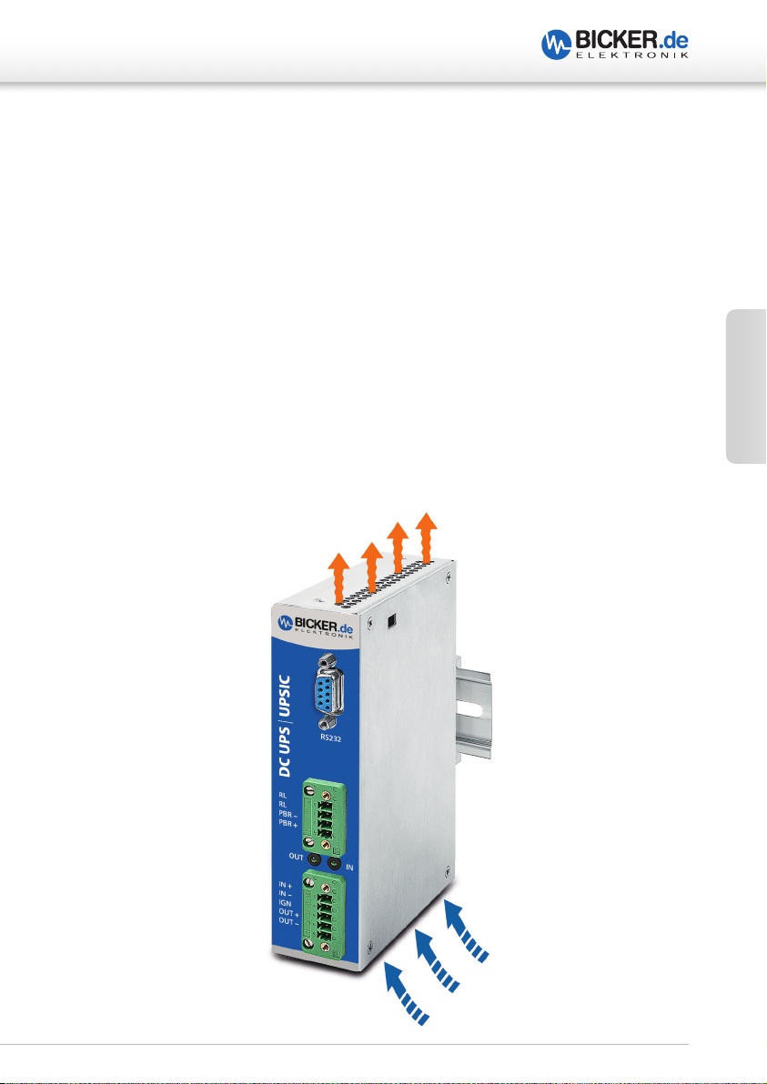
4 Konvektion und Einbaulage
Ausreichende Belüftung sowie freie Luftzirkulation müssen beim Einbau sichergestellt sein.
Es sollten keine Lüftungslöcher durch andere, benachbarte Komponenten verdeckt sein.
Bei den Geräten ist eine senkrechte Montage auf eine waagerechte Schiene (Hutschienen
nach EN 60715) empfehlenswert, um die bestmögliche Konvektion der USV zu erreichen.
Eine andere Einbaulage ist möglich, ein Betrieb bis +70 °C Umgebungstemperatur kann
dadurch aber nicht mehr gewährleistet werden.
Deutsch
5
Page 6

DC2412-UPSD | DC2412-UPS-LDD | UPSIC-1205D | UPSIC-2403D
5 Inbetriebnahme
5.1 DC2412-UPS-LDD
Um das Gerät einzuschalten, muss die Ignition-Leitung mit der Eingangsleitung verbunden
werden. Nach einer Verzögerung von ca. 2 sec läuft das Gerät an, der Ausgang liefert 12 V
und die Superkondensatoren werden geladen. Nach dem Entfernen des Ignition-Signals
schaltet der DC/DC-Wandler nach ca. 5 sec ab, um den Stromverbrauch zu minimieren.*
5.2 DC2412-UPSD
Nach Anlegen der Versorgungsspannung läuft das Gerät an, der Ausgang liefert 12 V und
die Supercaps werden geladen.*
5.3 UPSIC-1205D / UPSIC-2403D
Deutsch
Nach Anlegen der Versorgungsspannung (UPSIC-1205D Vin> 11.5 V, UPSIC-2403D Vin> 22.5 V)
wird diese, verringert durch einen stromabhängigen Spannungsabfall, an den
Ausgangweitergeleitet (V
Das Gerät lädt die Superkondensatoren und überwacht die Spannungsschwellen am
Eingang (USV-Funktion).*
Achtung beim Einsatz der UPSIC-1205D/UPSIC-2403D!
Bedenken Sie den Spannungsabfall der Zuleitung. Der maximale Ladestrom kann bei zu
langen Leitungen zu hohen Spannungsabfällen führen. Ist der Spannungsabfall zu hoch,
kann es zu einer Unterschreitung des Schwellwertes kommen und ein unbeabsichtiger
Power Fail ausgelöst werden. Stellen Sie sicher, dass auch bei maximaler Last die Spannung
direkt an den Eingangsbuchsen des Gerätes die 11.5 V bzw 22.5 V nicht unterschreitet.
= Vin - 0.3 V bei Maximalstrom).
out
Achtung beim Einsatz von allen hier beschriebenen Geräten!
Auch beim Entfernen des Ignition-Signals oder Trennen der Versorgung läuft das Gerät
bis zum Entladen der Superkondensatoren eigenständig weiter und liefert Spannung
am Ausgang. Ein Kurzschluss direkt am Ausgang des Geräts kann zur Schädigung oder
Zerstörung führen. Erst ab einer bestimmten Impedanz (L > 50 nH, R > 50 mΩ) kann ein
Schutz gewährleistet werden. Auch nach dem Trennen der Versorgung ist Leistung am
Ausgang vorhanden.
* Die Ausgangsspannung liegt erst bei 90 % Ladung vor, wenn die Option der Vorladung der
Supercaps eingestellt ist (siehe S. 13 DIP-Switch-Einstellungen DIP 3).
6
Page 7

DC2412-UPSD | DC2412-UPS-LDD | UPSIC-1205D | UPSIC-2403D
6 Schutz gegen Überspannung* (nur DC2412-UPS-LDD)
Überspannungsspitzen (V
vom Gerät abgefangen werden.
Dauert eine Überspannung länger als 400 ms, wird der Eingang getrennt und die
Backup-Funktion beginnt. Ein Power Fail wird ausgelöst.
Nach dem Abschalten durch Überspannung muss der Eingang getrennt oder
unterbrochen werden, damit das Gerät erneut startet (engl.: Latch).
Dies erfolgt durch Trennung und wieder Anschließen der Versorgungsspannung.
* „Load Dump“-Funktion
> 32 VDC…<123 V) können für eine Dauer bis 400 ms
in
7 Ladezeit der Superkondensatoren
Der Hauptanteil des Stromes wird auf den Ausgang übertragen, ein Teil wird zum Laden
der Superkondensatoren verwendet. Bei niedrigen Lasten steht entsprechend mehr
Ladestrom zur Verfügung und die Ladezeit ist kürzer.
Ladezeit ohne Last <60 s
Ladezeit bei Volllast ca. 2 ½ Minuten
Deutsch
8 Verhalten bei Überlast / Kurzschluss
Das Gerät ist gegen Verpolung, Überspannung* und Überlast abgesichert. Im Falle
einer Überlast schaltet das Gerät ab und läuft automatisch weiter, sobald sich der
Ausgangsstrom wieder im spezifizierten Bereich befindet bzw. die Überlast nicht mehr
anliegt.
* DC2412-UPS-LDD
7
Page 8

DC2412-UPSD | DC2412-UPS-LDD | UPSIC-1205D | UPSIC-2403D
A5
A
9 Verhalten bei Überschreiten der maximalen Pufferzeit
Die Pufferzeiten sollten nicht überschritten werden. Das System sollte innerhalb
der Pufferzeit heruntergefahren sein. Falls es zu einer Überschreitung der Pufferzeit
kommt, werden die Supercaps tiefentladen und in Abhängigkeit vom Strom bricht die
Ausgangsspannung zusammen.
DC2412-UPSD / DC2412-UPS-LDD / UPSIC-1205D
Standby @ No Load >30 min,
180 sec.
170 sec.
160 sec.
150 sec.
140 sec.
Deutsch
130 sec.
120 sec.
110 sec.
100 sec.
90 sec.
80 sec.
Backup time
70 sec.
60 sec.
50 sec.
40 sec.
30 sec.
20 sec.
10 sec.
0 sec.
0.0 A0.5 A1.0 A1.5 A2.0 A2.5 A3.0 A3.5 A4.0 A4.5
@ nom. Cap. & 25 °C
Anwendungsbeispiel mit
mITX Board IMB-154
(Parameter siehe unten)
Output current
.0
Parameter des Testsystems für die Backup-Kurve
Board IMB-154 L0.36
SN: 59M0X2003883
CPU: Braswell N3150; 4x 1.60GHz
RAM 2 x 4GB / DDR3 SO-DIMM
1600MHz FB
Type: CIR-S3SUSKA 1604G
SN: CIR 154630106
CIR 154630106
ROM 1x mSATA 32GB
Type: CIE MSM300M JB032GS
SN: CIE164905767
OS Microsoft Windows 10 Enterprise Evaluation Version 1511
Build 10586.589 (2016/09/16)
Test Software BurnInTest V7.1 Pro
Test results 100 % load: 1min. 43 sec. = 103sec
8
Page 9

DC2412-UPSD | DC2412-UPS-LDD | UPSIC-1205D | UPSIC-2403D
A2
A
UPSIC-2403D
Standby @ No Load >30 min,
@ nom.)Cap. & 25 °C
180 sec.
170 sec.
160 sec.
Backup time (sec)
150 sec.
140 sec.
130 sec.
120 sec.
110 sec.
100 sec.
90 sec.
80 sec.
70 sec.
60 sec.
50 sec.
40 sec.
30 sec.
20 sec.
10 sec.
0 sec.
0.0 A 0.5 A 1.0 A1.5 A2.0
Anwendungsbeispiel mit
mITX Board IMB-154
(Parameter siehe unten)
Output current
Parameter des Testsystems für die Backup-Kurve (wurde nicht mit 24 V-Version getestet)
Board IMB-154 L0.36
SN: 59M0X2003883
CPU: Braswell N3150; 4x 1.60GHz
RAM 2 x 4GB / DDR3 SO-DIMM
1600MHz FB
Type: CIR-S3SUSKA 1604G
SN: CIR 154630106
CIR 154630106
ROM 1x mSATA 32GB
Type: CIE MSM300M JB032GS
SN: CIE164905767
OS Microsoft Windows 10 Enterprise Evaluation
Version 1511
Build 10586.589 (2016/09/16)
Test Software BurnInTest V7.1 Pro
Deutsch
.5
9
Page 10
DC2412-UPSD | DC2412-UPS-LDD | UPSIC-1205D | UPSIC-2403D
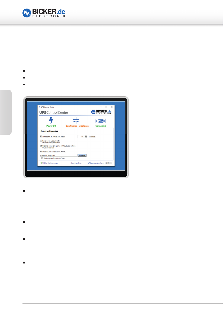
10 Software UPS Control Center
Die Software steht auf unserer Hompage www.bicker.de direkt beim Produkt zum
kostenlosen Download zur Verfügung.
Die Software kann unter folgenden Systemen betrieben werden:
Ab Windows® 7 Home / Professional / Enterprise / Embedded 32bit und 64bit
Ab .Net Framework 4.5
Serial Com-Port
Deutsch
Shutdown
Einstellungen
Shutdown at Power fail after: Wenn aktiviert, wird das Betriebssystem nach der eingestellten Zeit „Heruntergefahren“. Die Zeit kann durch Klick auf Pfeil nach unten in
Sekunden-Schritten ausgewählt werden oder der Benutzer gibt die Zeit manuell im
Format Stunde:Minuten:Sekunden ein.
Save open documents: Wenn aktiviert, werden geöffnete Dokumente gesichert, falls
das Programm den Tastaturbefehl „Str+S“ unterstützt.
Closing open programs without user action: Nur auswählbar, wenn einer der beiden oberen Felder aktiviert ist. Wenn aktiviert, werden geöffnete Programme, die sich
beim Herunterfahren nicht selbst schließen, hart beendet.
Execute file at shutdown: Wenn aktiviert, wird das ausgewählte Programm oder Skript
/ Batch ausgeführt bevor das Betriebssystem heruntergefahren wird. Die interne
Programmierroutine von »UPS Control Center« stellt sicher, dass das Programm oder
Skript/Batch zu Ende ausgeführt wird, bevor das System herunterfährt. Über die Schaltfläche
„Choose file“ können Sie das auszuführende Programm oder Skript/Batch auswählen.
10
Page 11

DC2412-UPSD | DC2412-UPS-LDD | UPSIC-1205D | UPSIC-2403D
11 Integriertes µExtension Modul
Das standardmäßig integrierte µExtension Modul PSZ-1063 ist ein intelligentes
Zusatzmodul mit vielfältigen Features.
11.1 Data Monitoring
Eine kontinuierliche Betriebsdatenerfassung gestattet „Data Monitoring“ in Echtzeit.
Hierbei werden die Daten über die I²C-Schnittstelle der UPSIC- und DC2412-UPS-Geräte
kontinuierlich erfasst und im µExtension Modul gespeichert. Über die implementierte
RS232-Schnittstelle am Modul können die Daten wiederum an den Host weitergereicht
werden, was eine einfache Implementierung in das System ermöglicht.
11.2 Integrierte Reboot-Funktion
Eine weitere Kernfunktion des Moduls ist das Reboot-Feature, das den automatischen Neustart des Systems aktiviert, sobald die Eingangsspannung während des
Herunterfahrens oder zu einem späteren Zeitpunkt wiederkehrt. Die Startfunktion des
Mainboards kann hier bei anliegender Eingangsspannung ganz einfach über das BIOS
aktiviert werden.
11.3 Kontrollierte Freigabe der Ausgangsspannung
Die Ausgangs- bzw. Versorgungsfreigabe an das System wird, wenn gewünscht, durch
eine Sicherheitsfunktion geregelt, d.h. sie erfolgt erst, wenn die Superkondensatoren 90 %
Ihrer Kapazität erreicht haben. Ein sicheres Herunterfahren des Systems ist somit immer
gewährleistet.
Deutsch
11.4 Softwareunabhängiger Betrieb
Die USV kann am Host auch ohne Software betrieben werden. Die Konfiguration der
Zeitwerte ist über den DIP-Schalter problemlos einstellbar und das Modul generiert das
Auslösesignal zum Herunterfahren / Abschalten des Systems über das Shutdown-Signal.
Die Optionen für softwaregesteuerte Einstellungen von Zeiten und zum Herunterfahren
über das UPS Control Center bleiben natürlich bestehen.
11
Page 12

DC2412-UPSD | DC2412-UPS-LDD | UPSIC-1205D | UPSIC-2403D
DC UPS | UPSIC
RL
PBR –
PBR +
INOUT
RL
RS232
IN –
IGN
OUT +
OUT –
IN +
12 Anschlüsse und Einstellungen
12.1 Gehäusezeichnung
9 mm
103 mm
29 mm
Deutsch
147 mm
36 mm
1ON23456
Enclosure opening
for DIP switch setup
SD(RB)PF
CAPS FULL
1ON23456
Power Fail: relay contact closed Pin 3 to Pin 4 = 0 Ω
0.5 A @ 125 VAC / 1 A @ 24 VDC
12
Page 13

DC2412-UPSD | DC2412-UPS-LDD | UPSIC-1205D | UPSIC-2403D
12.2 Kurzübersicht Pinbelegung und DIP-Switch-Einstellungen
DIP-Switch-EinstellungenPinbelegung RS232 / D-SUB
PIN SIGNAL
DCD at PC – Detection cable connected
1
TXD (is connected to RXT at PC)
2
RXD (is connected to TXD at PC)
3
Shutdown signal detection
4
GND
5
DSR at PC – Detection caps loading status
6
RTS at PC – Supply voltage
7
CTS at PC – Power Fail detection
8
N/A
9
Pinbelegung RL / PBR
PIN SIGNAL
04 / RL Relay connection
03 / RL Relay connection
02 / PBR – (V –) Shutdown-Signal (Impuls 200-400 ms)
01 / PBR + (V +) Shutdown-Signal (Impuls 200-400 ms)
Pinbelegung IN / IGN / OUT
SD(RB)PF
CAPS FULL
1ON23456
Power Fail (PF) - Timer
6 5 4 PIN
ON ON ON Software
OFF ON ON 3s
ON OFF ON 8s
OFF OFF ON 20s
ON ON OFF 40s
OFF ON OFF 60s
ON OFF OFF 100s
OFF OFF OFF 150s
Output release
PIN 3
ON Output released
when V
over 90 %
CAP
Deutsch
PIN SIGNAL
05 / IN + V + Input
04 / IN – V – Input
03 / IGN Ignition signal (nur DC2412-UPS-LDD)
02 / OUT + V + Output
01 / OUT – V – Output
Shutdown Timer
PIN 2 1
No Reboot ON ON
Reboot after 10s OFF ON
Reboot after 30s ON OFF
Reboot after 60s OFF OFF
13
Page 14

DC2412-UPSD | DC2412-UPS-LDD | UPSIC-1205D | UPSIC-2403D
12.3 Frontanschluss RS232 (D-SUB)
Die Verbindung zum Computersystem wird mit einem
handelsüblichen D-SUB-Verbindungskabel (1:1, 9-pol.)
hergestellt (nicht im Lieferumfang enthalten).
Pinbelegung RS232 (D-SUB)
PIN SIGNAL
DCD at PC – Detection cable connected
1
TXD (is connected to RXT at PC)
2
RXD (is connected to TXD at PC)
3
Deutsch
Shutdown signal detection
4
GND
5
DSR at PC – Detection caps loading status
6
RTS at PC – Supply voltage
7
CTS at PC – Power Fail detection
8
N/A
9
Interne Verschaltung RS232 (D-SUB)
R348
4k7
J301,PIN6(CTSONPCORHOST)
Power Fail Low
Internal connection
Power Fail High
14
R343
100R
GND
R346
R347
Q321
PMBF170 PMBF170
Q308
4k7
4k7
J301,PIN1(DCDONPCORHOST)CABLECONNECTED
J301,PIN4(RTSONPCORHOST)USEDASSUPPLY
J301,PIN2(DSRPCORHOST)CAPSCHANGESTATE
High CAP<90% Low CAP > 90% or Full Charged
R345
100R
Low CAP <90%
Internal connection
High CAP >90% or Full Charged
Page 15

DC2412-UPSD | DC2412-UPS-LDD | UPSIC-1205D | UPSIC-2403D
12.4 Frontanschluss RL / PBR
Pinbelegung RL / PBR
PIN SIGNAL
04 / RL Relay connection
03 / RL Relay connection
02 / PBR – (V –) Shutdown-Signal (Impuls 200-400 ms)
01 / PBR + (V +) Shutdown-Signal (Impuls 200-400 ms)
Interne Verschaltung PBR + / PBR –
PBR +
PBR –
Verkabelungsbeispiel
PBR +PBR –
Deutsch
PIN GND
PIN Power_Button
Mainboard
15
Page 16

12.5 Frontanschluss IN / IGN / OUT
Pinbelegung IN / ING / OUT
PIN SIGNAL
05 / IN + V + Input
04 / IN – V – Input
03 / IGN Ignition signal (nur DC2412-UPS-LDD)
Deutsch
02 / OUT + V + Output
01 / OUT – V – Output
DC2412-UPSD | DC2412-UPS-LDD | UPSIC-1205D | UPSIC-2403D
12.6 LED-Anzeige
Oberhalb der Ein- und Ausgänge IN / IGN / OUT signalisieren
die beiden LEDs jeweils Vout_OK (Ausgangsspannung) und
Vin_OK (Eingangsspannung).
16
Page 17
DC2412-UPSD | DC2412-UPS-LDD | UPSIC-1205D | UPSIC-2403D
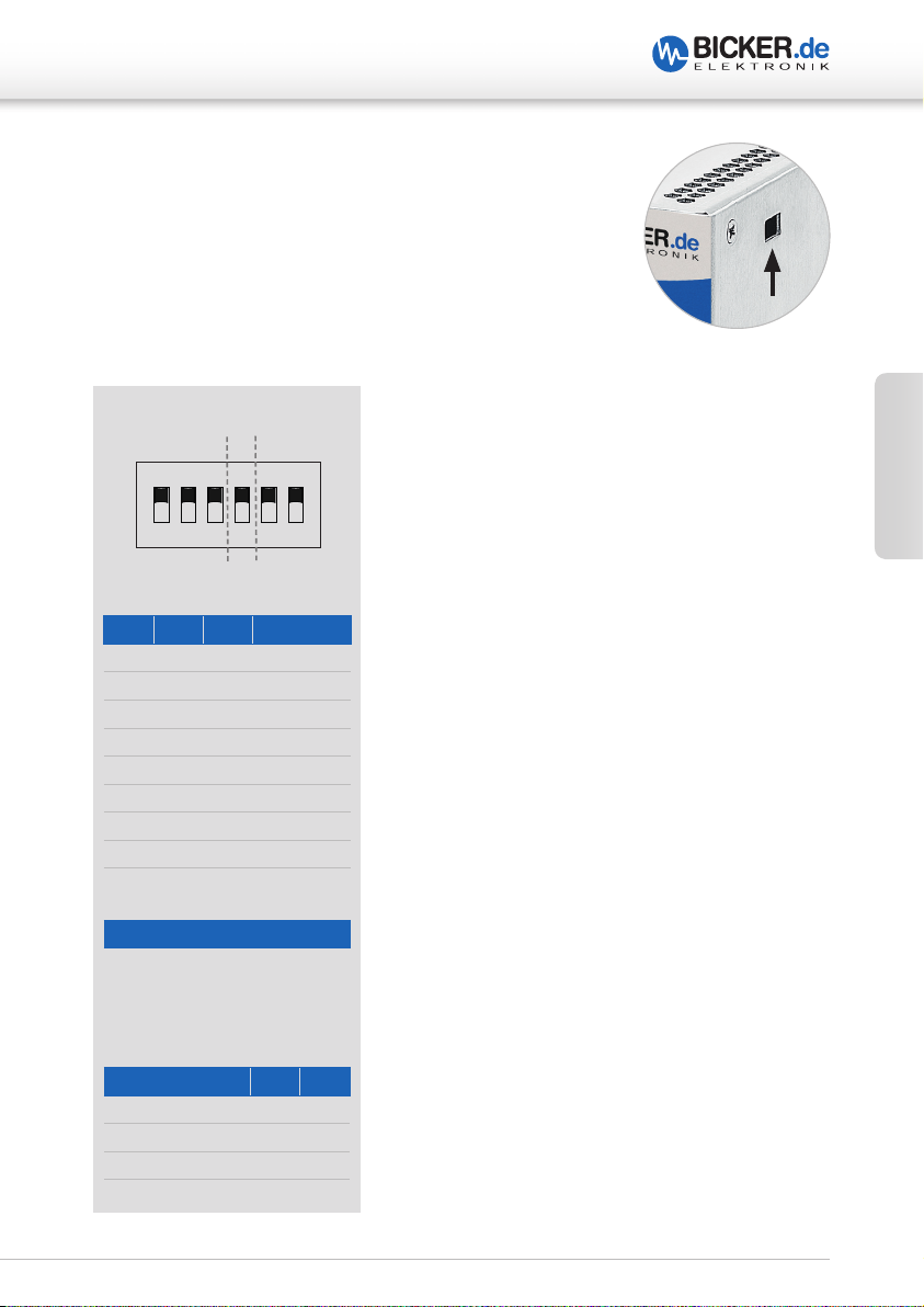
12.7 DIP-Switch
Der interne DIP-Switch kann über die dargestellte
Öffnung im Gehäuse konfiguriert werden.
DIP-Switch-Einstellungen
SD(RB)PF
CAPS FULL
1ON23456
Power Fail (PF) - Timer
6 5 4 PIN
ON ON ON Software
OFF ON ON 3s
ON OFF ON 8s
OFF OFF ON 20s
ON ON OFF 40s
OFF ON OFF 60s
ON OFF OFF 100s
OFF OFF OFF 150s
Deutsch
Output release
PIN 3
ON Output released
when V
over 90 %
CAP
Shutdown Timer
PIN 2 1
No Reboot ON ON
Reboot after 10s OFF ON
Reboot after 30s ON OFF
Reboot after 60s OFF OFF
17
Page 18

DC2412-UPSD | DC2412-UPS-LDD | UPSIC-1205D | UPSIC-2403D
13 Konfiguration
Einstellen der Pufferzeit
Power-Fail (PF)-Timer Betrifft die Backup-Time. Die Zeit bei einem
Stromausfall, nach der ein Shutdown-Signal an den
PC oder Host gesendet wird. Wenn innerhalb dieser
Zeit die Spannung netzseitig am Eingang wiederkehrt,
wird nichts unternommen. Dieser Befehl kann entweder über die Software „UPS Control Center“ (RS232Anbindung via D-SUB notwendig) oder über den
Power Button Press (via PBR + / PBR –) an den PC oder
Deutsch
Shutdown-Timer Beschreibt die Zeit, die dem System zur Verfügung
Host weitergeleitet werden.
steht, um geordnet herunterzufahren. Nach Ablauf des
PF-Timers wird diese verwendet, um den PC oder Host
herunterzufahren. Ist diese Zeit verstrichen, wird der
Ausgang für 8s getrennt. Wenn während dieser Zeit die
Spannung wiederkehrt, wird der Ausgang trotzdem
getrennt, um das System erneut zu starten.
NORMAL
V
IN
V
OUT
18
PF-TIMER SHUTDOWN-TIMER REBOOT= 8s
Page 19

DC2412-UPSD | DC2412-UPS-LDD | UPSIC-1205D | UPSIC-2403D
A Einsatz mit Power Button Press
Hier wird das Shutdown-Signal über ein zweiadriges Kabel an den Power Button des
Mainboards übertragen (200…500ms, Low - Taster). Die Auswahl am Dip-Schalter für den
PF-Timer (siehe Tabelle PF-Timer) muss hier ungleich „ON,ON,ON“ gewählt werden, um
diese Funktion zu aktivieren. Eine Vorgehensweise für die Einstellung der Dip-Schalter,
um das System für maximale Überbrückungszeit zu konfigurieren, wird in folgenden
Schritten beschrieben:
1. Feststellen, wie lang das System bei maximaler Leistungsaufnahme überbrückt
werden kann. Wenn die Leistungsaufnahme der Applikation bekannt ist, kann die
Überbrückungszeit aus den entsprechenden Datenblättern entnommen werden. Der
Wert entspricht t
in Sekunden.
BACKUP
2. Messen der Zeit, die das System benötigt, um geordnet herunterzufahren. Der Wert
entspricht t
SHUTDOWN
in Sekunden.
3. Stellen des PF-Timers auf den Wert:
PF-Timer
*(Marge für End-Of-Life und Toleranzen aufgrund der Temperatur)
[s] = (t
DIP
BACKUP
x 0,6*) – t
SHUTDOWN
Hierbei immer den nächst kleineren Wert am Dip-Schalter wählen.
Bei einem Stromausfall während des Vin Starts sollte die Bootzeit des Systems
ebenfalls beachtet werden.
4. Wählen des Shutdown-Timers so groß wie t
SHUTDOWN
. Hierbei am Dip-Schalter den
nächst größeren Wert einstellen, damit das System nicht während des Herunterfahrens
unterbrochen wird.
Die oben genannte Prozedur dient nur als Beispiel. Die Einstellungen können frei gewählt
werden, um das System nach den eigenen Anforderungen zu optimieren.
Nach Ablauf der Zeit des Shutdown-Timers wird das System für 8s getrennt (Reboot
Time). Kehrt innerhalb der Shutdown-Time oder der Reboot-Time die Versorgung wieder
zurück, wird das System nach Ablauf der 8s gestartet. (siehe Diagramm Seite 18)
Deutsch
Keine Reboot Funktion
Die Einstellung „ON,ON“ am Shutdown-Timer bedeutet, dass das System direkt nach
Ablauf der PF-Timer Einstellung getrennt wird und ausgeschaltet bleibt.
19
Page 20

DC2412-UPSD | DC2412-UPS-LDD | UPSIC-1205D | UPSIC-2403D
Transfer Packet
Control
Byte
Data Packet
Control
Byte
Header
D A T A
Byte 0
Byte 1
Byte 2
Byte 3
Byte 4 to 254 (can be null)
Last Byte
ASCII
‘SOH’
(0x01)
Size of
Data
Packet
Command
Index
Command
from List
Transfer or Received Data
ASCII ‘EOT’
(0x04)
=
‘Size of
Header’ +
‘Size of
used Data’
B Einsatz mit Software „UPS Control Center“
Der Unterschied zu Methode A (Einsatz mit Power Button Press) liegt darin, dass das
Herunterfahren am PC/Host (Shutdown- Befehl) nicht mit dem Power Button des
Mainboards (via PBR + / PBR –) durchgeführt wird, sondern über die Software (RS232Anbindung via D-SUB notwendig).
Um die Funktion „per Software“ korrekt zu konfigurieren ist es notwendig, die einge stellte Zeit im Feld „Shutdown at Power Fail after:“ auch am DIP-Schalter S2 einzustellen.
Die Zeit, die dem System zum Herunterfahren zur Verfügung steht, muss weiterhin über
den S2 Shutdown-Timer gewählt werden.
Nach Ablauf der Shutdown-Time wird das System für 8s getrennt (Reboot). Kehrt inner-
Deutsch
halb der Shutdown-Time oder der Reboot-Time die Versorgung wieder zurück, wird das
System nach Ablauf der 8s gestartet. (siehe Tabelle Shutdown-Timer)
C Kapazität über 90 % am PIN 3
Mit dieser Einstellung wird sichergestellt, dass die Versorgung erst an das System weitergegeben wird, wenn die Ladung der Superkondensatoren die 90 % erreicht hat. Dies ist
auch nach einem Reboot der Fall und soll sicherstellen, dass die Energie reicht um das
System immer sicher herunterzufahren.
20
Page 21

DC2412-UPSD | DC2412-UPS-LDD | UPSIC-1205D | UPSIC-2403D
Transfer Packet
Data Packet
Header
D A T A
Byte 0
Byte 1
Byte 2
Byte 3
Byte 4 to 254 (can be null)
Last Byte
Size of
Packet
=
‘Size of
used Data’
14 Kommunikationsprotokoll RS232
Transfer Packet - Beschreibung
Die Beschreibung des Protokolls bezieht sich auf die serielle Schnittstelle RS232. Das
Protokoll gilt zugleich für gesendete und empfangene Daten.
Control
Byte
ASCII
‘SOH’
(0x01)
Data
Header’ +
‘Size of
Command
Index
Command
from List
Transfer or Received Data
Control
Byte
ASCII ‘EOT’
(0x04)
Beschreibung
Der Datentransfer beginnt immer mit einem Startzeichen (0x01) und endet mit einem
Schlusszeichen (0x04). Nach dem Senden des Startsignals folgt der “Header” mit einer
Größe von 3 Byte. Der Header beinhaltet Informationen über die Größe des Datenpakets,
den Befehlsindex und die Befehls ID. Nach Übermittlung des Datenpakets wird die
Übertragung mit dem Schlusszeichen (0x04) beendet.
Verbindungsdaten RS232
Baudrate 38400
Data length 8-bit
Stop bit 1
Parity disabled
Deutsch
21
Page 22

DC2412-UPSD | DC2412-UPS-LDD | UPSIC-1205D | UPSIC-2403D
15 Befehlsliste
Der Befehlsindex (Command Index) ist immer 0x03.
GetInputVoltage() 0x25
This read-word function shows the measured input voltage of the UPS.
Cmd Name Access Type Min. Max Unit
0x25 GetInputVoltage() R Int16 0 32768 mV
Transfer packet: 0x01 0x03 0x03 0x25 0x04
GetOutputVoltage() 0x27
This read-word function shows the measured output voltage of the UPS.
Deutsch
Cmd Name Access Type Min. Max Unit
0x27 GetOutputVoltage() R Int16 0 32768 mV
Transfer packet: 0x01 0x03 0x03 0x27 0x04
GetInputCurrent() 0x28
This read-word function shows the measured input current of the UPS.
Cmd Name Access Type Min. Max Unit
0x28 GetInputCurrent () R Int16 0 32768 mA
Transfer packet: 0x01 0x03 0x03 0x28 0x04
GetChargeCurrent() 0x29
This read-word-function shows the measured charge current of the UPS.
Cmd Name Access Type Min. Max Unit
0x29 GetChargeCurrent () R Int16 -32768 32768 mA
Negative numbers indicate a discharge.
Transfer packet: 0x01 0x03 0x03 0x29 0x04
GetCapStackVoltage() 0x26
This read-word-function shows the measured voltage at the capacitor stack of the UPS.
Cmd Name Access Type Min. Max Unit
0x26 GetCapStackVoltage() R Int16 0 32768 mV
Transfer packet: 0x01 0x03 0x03 0x26 0x04
22
Page 23

DC2412-UPSD | DC2412-UPS-LDD | UPSIC-1205D | UPSIC-2403D
GetVcap1Voltage() 0x20
This read-word-function shows the measured voltage at capacitor 1.
Cmd Name Access Type Min. Max Unit
0x20 GetVcap1Voltage() R Int16 0 5000 mV
Transfer packet: 0x01 0x03 0x03 0x20 0x04
GetVcap2Voltage() 0x21
This read-word-function shows the measured voltage at capacitor 2.
Cmd Name Access Type Min. Max Unit
0x21 GetVcap2Voltage() R Int16 0 5000 mV
Transfer packet: 0x01 0x03 0x03 0x21 0x04
GetVcap3Voltage() 0x22
This read-word-function shows the measured voltage at capacitor 3.
Cmd Name Access Type Min. Max Unit
0x22 GetVcap3Voltage() R Int16 0 5000 mV
Transfer packet: 0x01 0x03 0x03 0x22 0x04
GetVcap4Voltage() 0x23
This read-word-function shows the measured voltage at capacitor 4.
Cmd Name Access Type Min. Max Unit
0x23 GetVcap4Voltage() R Int16 0 5000 mV
Transfer packet: 0x01 0x03 0x03 0x23 0x04
Deutsch
GetCapacity() 0x1E
This read-word-function shows the measured capacity of the capacitor stack.
Cmd Name Access Type Min. Max Unit
0x1E GetCapacity() R Int16 0 1000 F
Transfer packet: 0x01 0x03 0x03 0x1E 0x04
GetEsr() 0x1F
This read-word-function shows the measured ESR of the capacitor stack.
Cmd Name Access Type Min. Max Unit
0x1F GetEsr() R Int16 0 1000 mΩ
Transfer packet: 0x01 0x03 0x03 0x1F 0x04
23
Page 24

DC2412-UPSD | DC2412-UPS-LDD | UPSIC-1205D | UPSIC-2403D
GetChargeStatusRegister() 0x1B
This read-word function returns the status information about the state of the charger
system.
Cmd Name Access Type Min. Max Unit
0x1B GetChargeStatusRegister() R Bit Field - - True / False
Transfer packet: 0x01 0x03 0x03 0x1B 0x04
Bit Field:
SD SU CV UV CL CG CS CB CD CC RV PF RV RV RV RV
LSB MSB
BIT Description
0 SD Shows that the device is in step-down (charging) mode.
Deutsch
1 SU Shows that the device is in step-up (backup) mode.
2 CV Shows that the charger is in constant voltage mode.
3 UV Shows that the charger is in undervoltage lockout.
4 CL Shows that the device is in input current limit.
5 CG Shows that the capacitor voltage is above power good threshold.
6 CS Shows that the capacitor manager is shunting.
7 CB Shows that the capacitor manager is balancing.
8 CD Shows that the charger is temporarily disabled for capacitance measurement.
9 CC Shows that the charger is in constant current mode.
10 RV Reserved Bit
11 PF Shows that the input voltage is below the Power Fail Input (PFI) threshold.
12 RV Reserved Bit
13 RV Reserved Bit
14 RV Reserved Bit
15 RV Reserved Bit
StartCapEsrMeasurement() 0x31
This read-word function initiates a capacitance and ESR measurement.
Cmd Name Access Type Min. Max Unit
0x31 StartCapEsrMeasurement() R Start - - -
Transfer packet: 0x01 0x03 0x03 0x31 0x04
24
Page 25

DC2412-UPSD | DC2412-UPS-LDD | UPSIC-1205D | UPSIC-2403D
GetMonitorStatusRegister() 0x1C
This read-word function returns the status information about the state of the monitoring
system.
Cmd Name Access Type Min. Max Unit
0x1C GetMonitorStatusRegister() R Bit Field - - True / False
Transfer packet: 0x01 0x03 0x03 0x1C 0x04
Bit Field:
MA MS CP CM EM CF EF RV PF PR RV RV RV RV RV RV
LSB MSB
BIT Description
0 MA Shows that the capacitance/ESR measurement is in progress.
1 MS
2 CP
Shows that the system is waiting programmed time to begin C/ESR
measurement.
Shows that the system is waiting for satisfactory conditions to begin C/ESR
measurement.
3 CM Shows that the capacitance measurement has completed.
4 EM Shows that the ESR measurement has completed.
5 CF Shows that the last attempted C measurement was unable to complete
6 EF Shows that the last attempted ESR measurement was unable to complete
7 RV Reserved Bit
8 PF
9 PR
This bit is set when VIN falls below the PFI threshold or the charger is unable to
charge. It is cleared only when power returns and the charger is able to charge.
This bit is set when the input is above the PFI threshold and the charger is able
to charge. It is cleared only when PF (Bit 8) is set.
10 RV Reserved Bit
11 RV Reserved Bit
12 RV Reserved Bit
13 RV Reserved Bit
14 RV Reserved Bit
15 RV Reserved Bit
Deutsch
25
Page 26

DC2412-UPSD | DC2412-UPS-LDD | UPSIC-1205D | UPSIC-2403D
SetTimeToShutdown() 0x32
This set-word function communicates to UPS that System Shutdown has been initiated
(Win-Software). This command has to be sent right before initiating System Shutdown.
Furthermore the Time Value in [sec.] for System Shutdown must be transmitted. After this
time the output is disconnected.
Cmd Name Access Type Min. Max Unit
0x32 SetTimeToShutdown() W UInt8 0 255 sec.
Transfer packet: 0x01 0x04 0x03 0x32 0xXX 0x04
0xXX: Time in hex format (e.g. 14hex=20s)
Deutsch
26
Page 27

DC2412-UPSD | DC2412-UPS-LDD | UPSIC-1205D | UPSIC-2403D
16 Wartung
Das Gerät enthält keine zu wartenden Teile. Im Fehlerfall sind die Stromquelle
auszuschalten und die Kabel zu entfernen.
17 Entsorgung
Elektrische und elektronische Geräte dürfen nicht in den Hausmüll! Entsorgen Sie das
Produkt am Ende seiner Lebensdauer gemäß den geltenden gesetzlichen Vorschriften.
Deutsch
27
Page 28

English
DC2412-UPSD | DC2412-UPS-LDD | UPSIC-1205D | UPSIC-2403D
DC2412-UPSD | DC2412-UPS-LDD
UPSIC-1205D | UPSIC-2403D
28
Page 29

DC2412-UPSD | DC2412-UPS-LDD | UPSIC-1205D | UPSIC-2403D
1 Intended use ............................................................................... 30
2 Safety instructions ..................................................................... 30
3 Technical data .............................................................................31
4 Convection and installation position .....................................31
5 Commissioning ...........................................................................32
5.1 DC2412-UPS-LDD .....................................................................................32
5.2 DC2412-UPSD .............................................................................................32
5.3 UPSIC-1205D/UPSIC-2403D ...............................................................32
6 Overvoltage protection („Load Dump“ function) ............... 33
7 Charging time of Supercaps .................................................... 33
8 Behaviour during overload / short circuit .............................33
9 Behaviour during exceed of maximum buffer time ...........34
10 Software UPS Control Center ..................................................36
11 Integrated μExtension module ............................................... 37
11.1 Data Monitoring ........................................................................................37
11.2 Integrated reboot function ................................................................37
11.3 Controlled release of output voltage ..........................................37
11.4 Software independent operation ..................................................37
12 Connections and settings .........................................................38
12.1 Drawing ..........................................................................................................38
12.2 Quick Reference Pin Assignment & DIP Switch Settings 39
12.3 Front connector RS232 (D-SUB) ......................................................40
12.4 Front connector RL / PBR ....................................................................41
12.5 Front connector IN / IGN / OUT ......................................................42
12.6 LED display ...................................................................................................42
12.7 DIP-Switch .....................................................................................................43
13 Configuration..............................................................................44
14 Communication protocol RS232 ............................................. 46
15 List of commands ....................................................................... 48
16 Maintenance ............................................................................... 53
17 Disposal........................................................................................53
English
29
Page 30

DC2412-UPSD | DC2412-UPS-LDD | UPSIC-1205D | UPSIC-2403D
1 Intended use
Congratulations for choosing a quality product!
This manual explains the components and properties. All information contained in this
manual has been revised thoroughly to ensure accuracy and completeness. Yet Bicker
Electronic accepts no liability for any omissions or faults. We will appreciate any notifications regarding faults, suggestions for improvements and criticism.
The intended use of DC/DC converters DC2412-UPSD and DC2412-UPS-LDD is the
conversion from 24 VDC to 12 VDC and bridging of short power failures. The intended
use of UPSIC-1205D and UPSIC-2403D UPS systems is to bridge short power failures. In
each case Supercapacitors (also called ultracapacitors or EDLC) serve as storage medium.
English
2 Safety instructions
Attention, danger of life! The device may not be changed, disassembled or rebuilt! Any other use than described here will damage the converter and can lead to dangers such as short circuit, fire, etc.! Direct shortcircuiting of Supercaps can cause flowing currents that lead to high heat!
Damage caused by non-observance of these operating instructions invalidates the guarantee. For further damages we do not accept liability! In
case of property damage or personal injury caused by improper handling
or non-observance of safety instructions, we assume no liability. Any
warranty claim expires!
30
Page 31

DC2412-UPSD | DC2412-UPS-LDD | UPSIC-1205D | UPSIC-2403D
3 Technical data
Be sure to read the data sheet before using the devices!
If this is not available, it can be read or downloaded from the Internet at www.bicker.
de. Here you will find important information such as input voltage, output power and
ambient temperature. The device must not be operated outside the specified values!
4 Convection and installation position
Sufficient ventilation and free air circulation must be ensured during installation. No
ventilation holes should be obscured by other neighboring components. With the
devices, a vertical installation on a horizontal rail (DIN-rails in accordance with EN 60715)
is recommended in order to achieve the best possible convection of the UPS. Another
mounting position is possible, but operation up to +70 °C ambient temperature can not
be guaranteed.
English
31
Page 32

DC2412-UPSD | DC2412-UPS-LDD | UPSIC-1205D | UPSIC-2403D
5 Commissioning
5.1 DC2412-UPS-LDD
To turn on the device, Ignition line must be connected to the input line. After a delay
of approx. 2 sec, the device starts up, the output supplies 12 V and the supercapacitors
are charged. After removing the Ignition signal, the DC/DC converter shuts off after
approximately 5 sec to minimize power consumption. *
5.2 DC2412-UPSD
When supply voltage is applied, the device starts up, the output supplies 12 V and the
supercaps are charged. *
5.3 UPSIC-1205D / UPSIC-2403D
English
After applying supply voltage (UPSIC-1205D Vin> 11.5 V, UPSIC-2403D Vin> 22.5 V) this is
forwarded to the output, reduced by a current-dependent voltage drop (V
at maximum current).
The device charges the supercapacitors and monitors the voltage thresholds at the input
(UPS function). *
Attention when using UPSIC-1205D/UPSIC-2403D!
Consider the voltage drop of the supply line. The maximum charging current can lead to
high voltage drops if the cables are too long. If the voltage drop is too high, the threshold
value can be undershot and an unintentional power fail triggered. Make sure that the
voltage at the input sockets of the device does not fall below the 11.5 V or 22.5 V, even at
maximum load.
= Vin - 0.3 V
out
Attention when using all devices described here!
Even when removing the ignition signal or disconnecting the power supply, the device
continues to operate independently and provides voltage at the output until the supercapacitors have been discharged. A short circuit directly at the output of the device can
lead to damage or destruction. Only from a certain impedance (L > 50 nH, R > 50 mΩ)
protection can be guaranteed. Even after disconnecting supply voltage, power is available
at the output.
* In case the option of pre-charging Supercaps is set (see page 39 DIP switch settings DIP 3), the
output voltage is not available until 90% charge of Supercaps.
32
Page 33

DC2412-UPSD | DC2412-UPS-LDD | UPSIC-1205D | UPSIC-2403D
6 Overvoltage protection* (DC2412-UPS-LDD only)
Overvoltage peaks (Vin > 32 VDC…<123 V) can be intercepted by the device
for up to 400 ms.
If an overvoltage takes longer than 400 ms, the input is disconnected and the backup
function starts. Power Fail is activated.
After switching off by overvoltage, the input must be disconnected or interrupt to
restart the device (Latch).
This is done by disconnecting and reconnecting the supply voltage.
* „Load Dump“ function
7 Charging time of Supercaps
The main part of the current is transferred to the output, a smaller part is used to charge
the Supercaps. At low loads there is correspondingly more charging current available and
the charging time is shorter.
Charging time without load <60 s
Charging time at full load app. 2 ½ minutes
English
8 Behaviour during overload / short circuit
The device is protected against polarity reversal, overvoltage* and overload. In case of
an overload, the device switches off and recovers automatically as soon as the output
current is within the specified range or the overload no longer exists.
* DC2412-UPS-LDD
33
Page 34

DC2412-UPSD | DC2412-UPS-LDD | UPSIC-1205D | UPSIC-2403D
A5
A
9 Behaviour during exceed of maximum buffer time
The buffer times should not be exceeded. The system should be shut down within the
buffer time. If buffer time exceeds, the super caps are deep-discharged and the output
voltage collapses in dependence of the current.
DC2412-UPSD / DC2412-UPS-LDD / UPSIC-1205D
Standby @ No Load >30 min,
180 sec.
170 sec.
160 sec.
150 sec.
140 sec.
English
130 sec.
120 sec.
110 sec.
100 sec.
90 sec.
80 sec.
Backup time
70 sec.
60 sec.
50 sec.
40 sec.
30 sec.
20 sec.
10 sec.
0 sec.
0.0 A0.5 A1.0 A1.5 A2.0 A2.5 A3.0 A3.5 A4.0 A4.5
@ nom. Cap. & 25 °C
Application example with
mITX Board IMB-154
(see parameters below)
Output current
.0
Parameters of the test system for the backup curve
Board IMB-154 L0.36
SN: 59M0X2003883
CPU: Braswell N3150; 4x 1.60GHz
RAM 2 x 4GB / DDR3 SO-DIMM
1600MHz FB
Type: CIR-S3SUSKA 1604G
SN: CIR 154630106
CIR 154630106
ROM 1x mSATA 32GB
Type: CIE MSM300M JB032GS
SN: CIE164905767
OS Microsoft Windows 10 Enterprise Evaluation Version 1511
Build 10586.589 (2016/09/16)
Test Software BurnInTest V7.1 Pro
Test results 100 % load: 1min. 43 sec. = 103sec
34
Page 35

DC2412-UPSD | DC2412-UPS-LDD | UPSIC-1205D | UPSIC-2403D
A2
A
UPSIC-2403D
Standby @ No Load >30 min,
@ nom.)Cap. & 25 °C
180 sec.
170 sec.
160 sec.
Backup time (sec)
150 sec.
140 sec.
130 sec.
120 sec.
110 sec.
100 sec.
90 sec.
80 sec.
70 sec.
60 sec.
50 sec.
40 sec.
30 sec.
20 sec.
10 sec.
0 sec.
0.0 A 0.5 A 1.0 A1.5 A2.0
Application example with
mITX Board IMB-154
(see parameters below)
Output current
Parameters of the test system for the backup curve (was not tested with 24 V type)
Board IMB-154 L0.36
SN: 59M0X2003883
CPU: Braswell N3150; 4x 1.60GHz
RAM 2 x 4GB / DDR3 SO-DIMM
1600MHz FB
Type: CIR-S3SUSKA 1604G
SN: CIR 154630106
CIR 154630106
ROM 1x mSATA 32GB
Type: CIE MSM300M JB032GS
SN: CIE164905767
OS Microsoft Windows 10 Enterprise Evaluation
Version 1511
Build 10586.589 (2016/09/16)
Test Software BurnInTest V7.1 Pro
English
.5
35
Page 36

DC2412-UPSD | DC2412-UPS-LDD | UPSIC-1205D | UPSIC-2403D
10 Software UPS Control Center
The UPS software is available for free download directly on the product page at
www.bicker.de.
The software runs under the following systems:
Windows® 7 Home / Professional / Enterprise / Embedded 32bit und 64bit or higher
.Net Framework 4.5 or higher
Serial Com-Port
English
Shutdown
Setting
Shutdown at ‚Power fail‘ after: When enabled, the operating system shuts down
after the set period of time. By clicking on the pull-down arrow the preset time can be
selected in second increments or set manually in the format hours:minutes:seconds by
the user.
Save open documents: When enabled, open documents are saved if the program
supports the keyboard command „Str + S“.
Closing open programs without user action: Choosable, if one of the checkboxes
above is activated. In case of activated, running programs will be closed (may cause data
loss) if they don‘t close automatically during shutdown.
Execute file at shutdown: When enabled, the selected program or script/batch is
executed before the operating system shuts down. The internal programming routine of
„UPS Control Center“ ensures that the program or script/batch is executed completely
before the computer shuts down. Please use the button „Choose File...“ to select the
program or script/batch to be executed.
36
Page 37

DC2412-UPSD | DC2412-UPS-LDD | UPSIC-1205D | UPSIC-2403D
11 Integrated μExtension module
The μExtension module PSZ-1063, integrated as a standard feature, is an intelligent
add-on module with a variety of features.
11.1 Data Monitoring
Continuous operational data collection allows „real-time data monitoring“. The data is
continuously collected via I²C interface of UPSIC and DC2412 UPS devices and stored
in the μExtension module. The implemented RS232 interface on the module allows to
forward data to the host, which ensures easy system implement.
11.2 Integrated reboot function
Another core feature of the module is the reboot function, which enables the system to
automatically reboot as soon as the input voltage returns during shutdown or at a later
time. The startup function of the mainboard can be easily activated via BIOS when input
voltage is present.
11.3 Controlled release of output voltage
It is possible to control output enable by a safety function. In this case, output enable
does not take place until the supercapacitors reach 90 % of their capacity. A safe shutdown of the system is thus always guaranteed.
English
11.4 Software independent operation
The UPS can also be operated without software on the host. The configuration of the time
values is easily adjustable via DIP switch and the module generates the shutdown signal.
Of couse, options for software-controlled time settings and shutdown via UPS Control
Center remain in effect.
37
Page 38

DC2412-UPSD | DC2412-UPS-LDD | UPSIC-1205D | UPSIC-2403D
DC UPS | UPSIC
RL
PBR –
PBR +
INOUT
RL
RS232
IN –
IGN
OUT +
OUT –
IN +
12 Connections and settings
12.1 Drawing
9 mm
103 mm
29 mm
English
147 mm
36 mm
1ON23456
Enclosure opening
for DIP switch setup
SD(RB)PF
CAPS FULL
1ON23456
Power Fail: relay contact closed Pin 3 to Pin 4 = 0 Ω
0.5 A @ 125 VAC / 1 A @ 24 VDC
38
Page 39

DC2412-UPSD | DC2412-UPS-LDD | UPSIC-1205D | UPSIC-2403D
12.2 Quick Reference Pin Assignment & DIP Switch Settings
DIP Switch SettingsPin Assignment RS232 / D-SUB
PIN SIGNAL
DCD at PC – Detection cable connected
1
TXD (is connected to RXT at PC)
2
RXD (is connected to TXD at PC)
3
Shutdown signal detection
4
GND
5
DSR at PC – Detection caps loading status
6
RTS at PC – Supply voltage
7
CTS at PC – Power Fail detection
8
N/A
9
Pinbelegung RL / PBR
PIN SIGNAL
04 / RL Relay connection
03 / RL Relay connection
02 / PBR – (V –) Shutdown-Signal (Impuls 200-400 ms)
01 / PBR + (V +) Shutdown-Signal (Impuls 200-400 ms)
Pinbelegung IN / IGN / OUT
SD(RB)PF
CAPS FULL
1ON23456
Power Fail (PF) - Timer
6 5 4 PIN
ON ON ON Software
OFF ON ON 3s
ON OFF ON 8s
OFF OFF ON 20s
ON ON OFF 40s
OFF ON OFF 60s
ON OFF OFF 100s
OFF OFF OFF 150s
Output release
PIN 3
ON Output released
when V
over 90 %
CAP
English
PIN SIGNAL
05 / IN + V + Input
04 / IN – V – Input
03 / IGN Ignition signal (nur DC2412-UPS-LDD)
02 / OUT + V + Output
01 / OUT – V – Output
Shutdown Timer
PIN 2 1
No Reboot ON ON
Reboot after 10s OFF ON
Reboot after 30s ON OFF
Reboot after 60s OFF OFF
39
Page 40

DC2412-UPSD | DC2412-UPS-LDD | UPSIC-1205D | UPSIC-2403D
12.3 Front connector RS232 (D-SUB)
The connection to computer system is established by a
commercially available D-SUB connection cable (1:1, 9-pin)
(not included in delivery!).
Pin Assignment RS232 (D-SUB)
PIN SIGNAL
DCD at PC – Detection cable connected
1
TXD (is connected to RXT at PC)
2
RXD (is connected to TXD at PC)
English
3
Shutdown signal detection
4
GND
5
DSR at PC – Detection caps loading status
6
RTS at PC – Supply voltage
7
CTS at PC – Power Fail detection
8
N/A
9
Internal interconnection RS232 (D-SUB)
R348
4k7
J301,PIN6(CTSONPCORHOST)
Power Fail Low
Internal connection
Power Fail High
40
R343
100R
Q321
PMBF170 PMBF170
GND
Q308
R346
4k7
R347
4k7
J301,PIN1(DCDONPCORHOST)CABLECONNECTED
J301,PIN4(RTSONPCORHOST)USEDASSUPPLY
J301,PIN2(DSRPCORHOST)CAPSCHANGESTATE
High CAP<90% Low CAP > 90% or Full Charged
R345
100R
Low CAP <90%
Internal connection
High CAP >90% or Full Charged
Page 41

DC2412-UPSD | DC2412-UPS-LDD | UPSIC-1205D | UPSIC-2403D
12.4 Front connector RL / PBR
Pin Assignment RL / PBR
PIN SIGNAL
04 / RL Relay connection
03 / RL Relay connection
02 / PBR – (V –) Shutdown-Signal (Impuls 200-400 ms)
01 / PBR + (V +) Shutdown-Signal (Impuls 200-400 ms)
Internal connection PBR + / PBR –
PBR +
PBR –
Example for cabling
PBR +PBR –
English
PIN GND
PIN Power_Button
Mainboard
41
Page 42

12.5 Front connector IN / IGN / OUT
Pin Assignment IN / ING / OUT
PIN SIGNAL
05 / IN + V + Input
04 / IN – V – Input
English
03 / IGN Ignition signal (nur DC2412-UPS-LDD)
02 / OUT + V + Output
01 / OUT – V – Output
DC2412-UPSD | DC2412-UPS-LDD | UPSIC-1205D | UPSIC-2403D
12.6 LED display
Above input and outputs IN / IGN / OUT two LEDs
signal Vout_OK (output voltage) and Vin_OK (input voltage).
42
Page 43

DC2412-UPSD | DC2412-UPS-LDD | UPSIC-1205D | UPSIC-2403D
12.7 DIP Switch
The internal DIP switch can be configured
via shown housing aperture.
DIP Switch Settings
SD(RB)PF
CAPS FULL
1ON23456
Power Fail (PF) - Timer
6 5 4 PIN
ON ON ON Software
OFF ON ON 3s
ON OFF ON 8s
OFF OFF ON 20s
ON ON OFF 40s
OFF ON OFF 60s
ON OFF OFF 100s
OFF OFF OFF 150s
English
Output release
PIN 3
ON Output released
when V
over 90 %
CAP
Shutdown Timer
PIN 2 1
No Reboot ON ON
Reboot after 10s OFF ON
Reboot after 30s ON OFF
Reboot after 60s OFF OFF
43
Page 44

DC2412-UPSD | DC2412-UPS-LDD | UPSIC-1205D | UPSIC-2403D
13 Configuration
Einstellen der Pufferzeit
Power-Fail (PF)-Timer Concerns the backup time. The time during a power
failure after which a shutdown signal is sent to the PC
or host. If within this time the mains voltage returns
to the input, nothing will be done. This command
can either be forwarded to the PC or host via „UPS
Control Center“ software (RS232 connection via D-SUB
required) or via Power Button Press (via PBR + / PBR -).
Shutdown-Timer Concerns the time which is available for the system to
English
shut down safely. After expiry of the PF-Timer this time
is used to shut down the PC or host. When this time has
elapsed, the output is cut off for 8s. If the input voltage
returns during this time the output still remains cut off
to initiate a new restart of the system.
NORMAL
V
IN
V
OUT
44
PF-TIMER SHUTDOWN-TIMER REBOOT= 8s
Page 45

DC2412-UPSD | DC2412-UPS-LDD | UPSIC-1205D | UPSIC-2403D
A Use with Power Button Press
The shutdown signal is sent to the power button of the mainboard via a two-core cable
(200...500ms low button). The setting at the DIP switch for the PF-timer (please see table
PF-Timer) has to be different to „ON,ON,ON“ to activate this function. In the following
comes a procedure for the setting of the DIP switch for the configuration of the maximum
hold-up time:
1. Identify maximum hold-up time of your system at maximum power consumption. If
power consumption of the application is known the hold-up time can be read out of
the according datasheets. The value corresponds to t
BACKUP
in seconds.
2. Measure the time which is needed by your system to shut down safe. This value
corresponds to t
SHUTDOWN
in seconds.
3. Set the PF-Timer to:
PF-Timer
*(Margin for End-Of-Life and tolerances due to temperature)
[s] = (t
DIP
BACKUP
x 0,6*) – t
SHUTDOWN
Always select the next lower value at the dip switch.
For a power failure during the Vin start the boot time of the system also has to be
taken into account.
4. Set the shutdown timer as high as t
SHUTDOWN
. Set value at DIP switch to next higher
value to make sure the system will not be interrupted during the shutdown process.
English
This procedure serves as one example. The settings can be chosen free to optimize the
system according to your own requirements.
After the time the shutdown timer has expired the system will be disconnected for eight
seconds (reboot time). If the power supply returns within the shutdown time or the
reboot time the system will be restarted after the eight seconds (please see diagram on
page 44)
No reboot function
A configuration of „ON,ON“ at the shutdown timer ensures that the system will be cut off
and stays off immediately after the PF-Timer setting.
45
Page 46

DC2412-UPSD | DC2412-UPS-LDD | UPSIC-1205D | UPSIC-2403D
Transfer Packet
Control
Byte
Data Packet
Control
Byte
Header
D A T A
Byte 0
Byte 1
Byte 2
Byte 3
Byte 4 to 254 (can be null)
Last Byte
ASCII
‘SOH’
(0x01)
Size of
Data
Packet
Command
Index
Command
from List
Transfer or Received Data
ASCII ‘EOT’
(0x04)
=
‘Size of
Header’ +
‘Size of
used Data’
B Use with software „UPS-Control Center“
The difference to method A (use of Power Button Press) is that shutdown on the PC / host
(shutdown command) is not performed with the power button of the mainboard (via
PBR + / PBR -), but via software ( RS232 connection via D-SUB necessary).
For the correct configuration of the function via software it is necessary to set the
chosen time in the field „Shutdown at power fail after:“ also at the DIP switch S2. The time
available to the system for shutdown must still be selected via S2 Shutdown-Timer.
After the shutdown time has expired the system will be disconnected for eight seconds
(reboot time). If the power supply returns within the shutdown time or the reboot time
the system will be restarted after the eight seconds (please see table Shutdown-Timer).
English
C Capacity over 90 % at PIN 3
This setting secures the supply will not be released to the system until the supercaps have
reached 90 % charge. This is also valid after a reboot situation and shall secure that there
is enough energy to shut down the system safe at any time.
46
Page 47

DC2412-UPSD | DC2412-UPS-LDD | UPSIC-1205D | UPSIC-2403D
Transfer Packet
Data Packet
Header
D A T A
Byte 0
Byte 1
Byte 2
Byte 3
Byte 4 to 254 (can be null)
Last Byte
Size of
Packet
=
‘Size of
used Data’
14 Communication protocol RS2322
Transfer packet - Description
The description refers to the serial interface RS232. The protocol is valid for sent and
received data as well.
Control
Byte
ASCII
‘SOH’
(0x01)
Data
Header’ +
‘Size of
Command
Index
Command
from List
Transfer or Received Data
Control
Byte
ASCII ‘EOT’
(0x04)
Description
The data transfer always begins with a start signal (0x01) and ends with an end signal
(0x04). After the start signal was sent the „Header“ follows with a size of 3 byte. The
Header contains information about the size of the data volume, the command index and
the command ID. After transmission of the data packet the transmittance is closed with
the end signal (0x04).
Connection data RS232
Baudrate 38400
Data length 8-bit
Stop bit 1
Parity disabled
English
47
Page 48

DC2412-UPSD | DC2412-UPS-LDD | UPSIC-1205D | UPSIC-2403D
15 List of commands
The command index is always 0x03.
GetInputVoltage() 0x25
This read-word function shows the measured input voltage of the UPS.
Cmd Name Access Type Min. Max Unit
0x25 GetInputVoltage() R Int16 0 32768 mV
Transfer packet: 0x01 0x03 0x03 0x25 0x04
GetOutputVoltage() 0x27
This read-word function shows the measured output voltage of the UPS.
English
Cmd Name Access Type Min. Max Unit
0x27 GetOutputVoltage() R Int16 0 32768 mV
Transfer packet: 0x01 0x03 0x03 0x27 0x04
GetInputCurrent() 0x28
This read-word function shows the measured input current of the UPS.
Cmd Name Access Type Min. Max Unit
0x28 GetInputCurrent () R Int16 0 32768 mA
Transfer packet: 0x01 0x03 0x03 0x28 0x04
GetChargeCurrent() 0x29
This read-word-function shows the measured charge current of the UPS.
Cmd Name Access Type Min. Max Unit
0x29 GetChargeCurrent () R Int16 -32768 32768 mA
Negative numbers indicate a discharge.
Transfer packet: 0x01 0x03 0x03 0x29 0x04
GetCapStackVoltage() 0x26
This read-word-function shows the measured voltage at the capacitor stack of the UPS.
Cmd Name Access Type Min. Max Unit
0x26 GetCapStackVoltage() R Int16 0 32768 mV
Transfer packet: 0x01 0x03 0x03 0x26 0x04
48
Page 49

DC2412-UPSD | DC2412-UPS-LDD | UPSIC-1205D | UPSIC-2403D
GetVcap1Voltage() 0x20
This read-word-function shows the measured voltage at capacitor 1.
Cmd Name Access Type Min. Max Unit
0x20 GetVcap1Voltage() R Int16 0 5000 mV
Transfer packet: 0x01 0x03 0x03 0x20 0x04
GetVcap2Voltage() 0x21
This read-word-function shows the measured voltage at capacitor 2.
Cmd Name Access Type Min. Max Unit
0x21 GetVcap2Voltage() R Int16 0 5000 mV
Transfer packet: 0x01 0x03 0x03 0x21 0x04
GetVcap3Voltage() 0x22
This read-word-function shows the measured voltage at capacitor 3.
Cmd Name Access Type Min. Max Unit
0x22 GetVcap3Voltage() R Int16 0 5000 mV
Transfer packet: 0x01 0x03 0x03 0x22 0x04
GetVcap4Voltage() 0x23
This read-word-function shows the measured voltage at capacitor 4.
Cmd Name Access Type Min. Max Unit
0x23 GetVcap4Voltage() R Int16 0 5000 mV
Transfer packet: 0x01 0x03 0x03 0x23 0x04
English
GetCapacity() 0x1E
This read-word-function shows the measured capacity of the capacitor stack.
Cmd Name Access Type Min. Max Unit
0x1E GetCapacity() R Int16 0 1000 F
Transfer packet: 0x01 0x03 0x03 0x1E 0x04
GetEsr() 0x1F
This read-word-function shows the measured ESR of the capacitor stack.
Cmd Name Access Type Min. Max Unit
0x1F GetEsr() R Int16 0 1000 mΩ
Transfer packet: 0x01 0x03 0x03 0x1F 0x04
49
Page 50

DC2412-UPSD | DC2412-UPS-LDD | UPSIC-1205D | UPSIC-2403D
GetChargeStatusRegister() 0x1B
This read-word function returns the status information about the state of the charger
system.
Cmd Name Access Type Min. Max Unit
0x1B GetChargeStatusRegister() R Bit Field - - True / False
Transfer packet: 0x01 0x03 0x03 0x1B 0x04
Bit Field:
SD SU CV UV CL CG CS CB CD CC RV PF RV RV RV RV
LSB MSB
BIT Description
0 SD Shows that the device is in step-down (charging) mode.
English
1 SU Shows that the device is in step-up (backup) mode.
2 CV Shows that the charger is in constant voltage mode.
3 UV Shows that the charger is in undervoltage lockout.
4 CL Shows that the device is in input current limit.
5 CG Shows that the capacitor voltage is above power good threshold.
6 CS Shows that the capacitor manager is shunting.
7 CB Shows that the capacitor manager is balancing.
8 CD Shows that the charger is temporarily disabled for capacitance measurement.
9 CC Shows that the charger is in constant current mode.
10 RV Reserved Bit
11 PF Shows that the input voltage is below the Power Fail Input (PFI) threshold.
12 RV Reserved Bit
13 RV Reserved Bit
14 RV Reserved Bit
15 RV Reserved Bit
StartCapEsrMeasurement() 0x31
This read-word function initiates a capacitance and ESR measurement.
Cmd Name Access Type Min. Max Unit
0x31 StartCapEsrMeasurement() R Start - - -
Transfer packet: 0x01 0x03 0x03 0x31 0x04
50
Page 51

DC2412-UPSD | DC2412-UPS-LDD | UPSIC-1205D | UPSIC-2403D
GetMonitorStatusRegister() 0x1C
This read-word function returns the status information about the state of the monitoring
system.
Cmd Name Access Type Min. Max Unit
0x1C GetMonitorStatusRegister() R Bit Field - - True / False
Transfer packet: 0x01 0x03 0x03 0x1C 0x04
Bit Field:
MA MS CP CM EM CF EF RV PF PR RV RV RV RV RV RV
LSB MSB
BIT Description
0 MA Shows that the capacitance/ESR measurement is in progress.
1 MS
2 CP
Shows that the system is waiting programmed time to begin C/ESR
measurement.
Shows that the system is waiting for satisfactory conditions to begin C/ESR
measurement.
3 CM Shows that the capacitance measurement has completed.
4 EM Shows that the ESR measurement has completed.
5 CF Shows that the last attempted C measurement was unable to complete
6 EF Shows that the last attempted ESR measurement was unable to complete
7 RV Reserved Bit
8 PF
9 PR
This bit is set when VIN falls below the PFI threshold or the charger is unable to
charge. It is cleared only when power returns and the charger is able to charge.
This bit is set when the input is above the PFI threshold and the charger is able
to charge. It is cleared only when PF (Bit 8) is set.
10 RV Reserved Bit
11 RV Reserved Bit
12 RV Reserved Bit
13 RV Reserved Bit
14 RV Reserved Bit
15 RV Reserved Bit
English
51
Page 52

DC2412-UPSD | DC2412-UPS-LDD | UPSIC-1205D | UPSIC-2403D
SetTimeToShutdown() 0x32
This set-word function communicates to UPS that System Shutdown has been initiated
(Win-Software). This command has to be sent right before initiating System Shutdown.
Furthermore the Time Value in [sec.] for System Shutdown must be transmitted. After this
time the output is disconnected.
Cmd Name Access Type Min. Max Unit
0x32 SetTimeToShutdown() W UInt8 0 255 sec.
Transfer packet: 0x01 0x04 0x03 0x32 0xXX 0x04
0xXX: Time in hex format (e.g. 14hex=20s)
English
52
Page 53

DC2412-UPSD | DC2412-UPS-LDD | UPSIC-1205D | UPSIC-2403D
16 Maintenance
This extension module contains no serviceable parts. In case of a malfunction the
power source has to be disconnected and cables have to be removed.
17 Disposal
Electric and electronic devices must not be disposed with domestic waste!
Dispose the product according legal regulations at the end of the life time.
English
53
Page 54

Irrtümer und technische Änderungen vorbehalten.
Windows® ist ein eingetragenes Warenzeichen der Firma Microsoft Corp.
Subject to errors and technical modifications.
Windows® is a registered trademark of Microsoft Corporation.
Stand/Issued: 06.03.2019
Bicker Elektronik GmbH
Ludwig-Auer-Straße 23
86609 Donauwörth · Germany
Tel. +49 (0) 906 70595-0
Fax +49 (0) 906 70595-55
E-Mail info@bicker.de
www.bicker.de
 Loading...