

Page 1
M-50, M-60, M-80 and M-8.3
VI-38
In-Wall Speaker Systems
Page 2
CONGRATULATIONS
TABLE OF CONTENTS
What you need to do the job
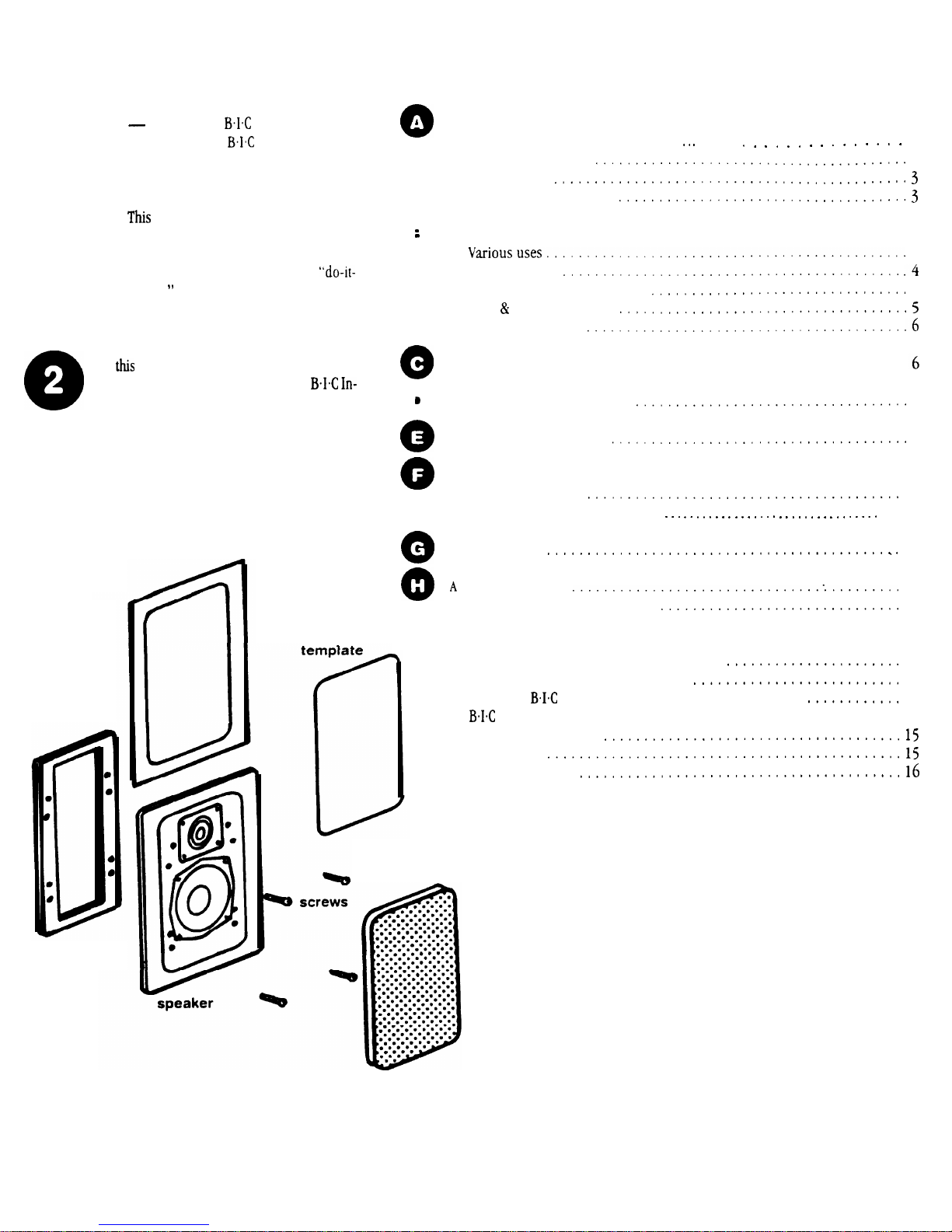
Speaker system parts inventory
on selecting
Wall-Mounted
Speakers. Like all
speakers, they
combine advanced acoustic technology
with durability and will provide years of
musical enjoyment.
manual is designed to make your
M-50, M-60, M-80, M-8.3 or VI-38
speakers as easy to install as they are to
listen to. If you’ve had any home
yourself
experience, you should find
installation of your new speakers a
simple job.
However, we suggest you read through
manual before starting out. If you
then decide that installing your
Wall Speakers is a bit beyond your skills,
we’ve included suggestions for locating
sources of affordable outside help.
mounting
template
mounting
bracket
masking
3
Tools for installation
3
Speaker wire.
Amplifier considerations
0
Where to put your speakers
4
Stereo imaging
Other acoustic considerations
5
Wall
ceiling surfaces
Speaker wire paths
Painting your speakers.
.......................................
0
Cutting holes for the speakers
Running connecting wires
Hooking up your speakers
At the speaker end
6
7
11
At the amplifier end..
11
Final assembly.
12
short “test drive”
12
A quick troubleshooting guide.
13
Further reading
Taking care of your new in-wall speakers.
13
More on amplifiers and impedances
14
Installing
Muro speakers during new construction
14
Muro M-50, M-60, M-80, M-8.3 and Venturi VI-38 descriptions
and specifications.
Outside help
grille
DRAWING 1
NOT SHOWN: packet of acoustic damping material
Page 3

WHAT YOU NEED
TO DO THE JOB
SPEAKER SYSTEM
PARTS INVENTORY
Before you get involved in the actual
installation process, it’s a good idea to
check for possible shipping damage and
identify parts and hardware.
You should have the parts shown in
Drawing 1:
0
‘ho (2)
In-wall loudspeaker
systems with attached grilles
0
(2) metal brackets
0
Eight (8) black metal screws (in
their own little zip-top bag)
0
Another clear plastic bag with little
rectangles of a black substance
wrapped in white paper (we’ll
explain this one later!)
0
(2) white cardboard mounting
templates
0
(2) white cardboard masking
templates for painting
If anything is missing after a thorough
search of the box and packing materials,
contact the dealer where you bought your
speakers.
Although BIG In-Wall Systems are
extremely well packed to withstand the
rigors of shipping, you should still
inspect them closely, especially if there
is any damage to the outside cartons. If
you find anything wrong, contact your
dealer or the shipper who delivered
the speakers.
TOOLS FOR INSTALLATION
IN EXISTING WALLS
It doesn’t take a whole workshop to
install your new speakers, just a few
simple tools:
A pencil
0
A
drill with a l-inch flat bit
0
A retractable utility knife or
keyhole saw
A length of stiff wire about 3 feet
long (a straightened wire coat
hanger works fine)
0
A
Phillips-head screw driver which
will fit the black screws included
with your speakers
0
A pair of diagonal pliers or wire
strippers
Some of the following may also be
needed, depending on the application.
0 A stud finder
0
Drill bit just slightly larger than
the diameter of one speaker wire
0
Plumb bob or small weight on a
string
0
Insulated staples for securing
speaker wire
0
Masking tape or foam
stick” tape
0
Paint and applicator for changing
grille
outer frame finish
0 A bubble level
SPEAKER WIRE
The amount of wire you’re going to
need will of course vary with speaker
placement (which we cover next). But
we’re covering the subject of wire now
because it’s something you may have to
go out and obtain along with whatever
tools you don’t already have.
What
kind to use
We recommend using inexpensive,
multi-stranded “zip-cord” for
to-speaker connections. Also called lamp
cord, it’s sold in pre-packed rolls and in
bulk displays at hardware, lighting and
home improvement stores. Zip-cord’s
outside covering (insulation) can be
transparent, black, brown, white, etc.
Color doesn’t matter. Thickness does.
Selecting the proper gauge
Wire is measured in “gauges.” For no
particularly good reason, the bigger the
number, the smaller the wire. For example,
is thinner than
The gauge of wire you need is determined by the distance between your
amplifier/receiver and the speakers. Use
the following chart as a guide:
Length
Minimum Gauge
Less than 10 ft.
18
10 to 50 ft.
16
Over 50 ft.
14
If in doubt, be safe and get a smaller
gauge (i.e. thicker wire). Using too thin
a gauge over a long distance can compro-
mise sound quality. And besides, there
isn’t a vast cost difference between
gauges, anyway.
How much to buy
Basically, more than you think you
need. As we noted earlier, a discussion of
lengths is sort of premature until you’ve
decided on exact placement, so you may
want to skip to page 4 and read the section on “‘Where to
put your speakers.”
But if you have a rough idea of the distance from your
to the speak-
ers, here are a few tips:
Because of the complicated paths
which are often required to route
wires, you’ll definitely need more
than the amount derived from
simple measurements.
Even if one speaker is a lot closer
to the amp than the other speaker,
you should use the same length of
wire for both paths. This insures
that both speakers will play at
equal volume.
Professional installers often use
the following rule of thumb:
the crow flies” amp to speaker
distance TIMES FIVE. That allows
enough for both speaker paths plus
a very healthy margin for unplanned
detours. Remember the electrician’s
favorite
adage: “You
can
cut
off extra wire, but
don’t stretch
worth a ah.
AMPLIFIER
CONSIDERATIONS
Virtually any receiver, power amplifier
or integrated amplifier can be used with
your
Ceiling Speakers. Although
Muro
are rated at 100 watts maxi-
mum input power, M-60’s at 110 watts,
at 120 watts,
at 120 watts,
and
at 125 watts, it’s OK to use a
more powerful amplifier if you take some
simple precautions, which we cover on
page 13 (‘Taking care
of your new
In-wall speakers”).
A more serious consideration is
whether or not you intend to power more
than one set of speakers with the same
amplifier or receiver. If you intend to
hook speakers to both “A” and
receiver outputs and then play both sets
of speakers at the same time, you should
read the section starting on page 14 of
this manual
(“More on amplifiers
and impedances”),
to avoid potential
problems.
Page 4
0
WHERE TO PUT
YOUR SPEAKERS
Placement can make all the difference
in how your
sound
install. There are at least three
“WHERE’S” and a “HOW” to factor into
your layout;
l
HOW you intend to use your speakers
l
WHERE they’ll sound best (stereo
imaging and acoustic considerations)
speaker systems
and how easy they are to
EXCELLENT
for stereo imaging
WHERE it’s possible to install
them (wall and ceiling surfaces)
l
WHERE they can be installed that
makes it easy to get wire to them
without remodeling your entire
house.
VARIOUS USES
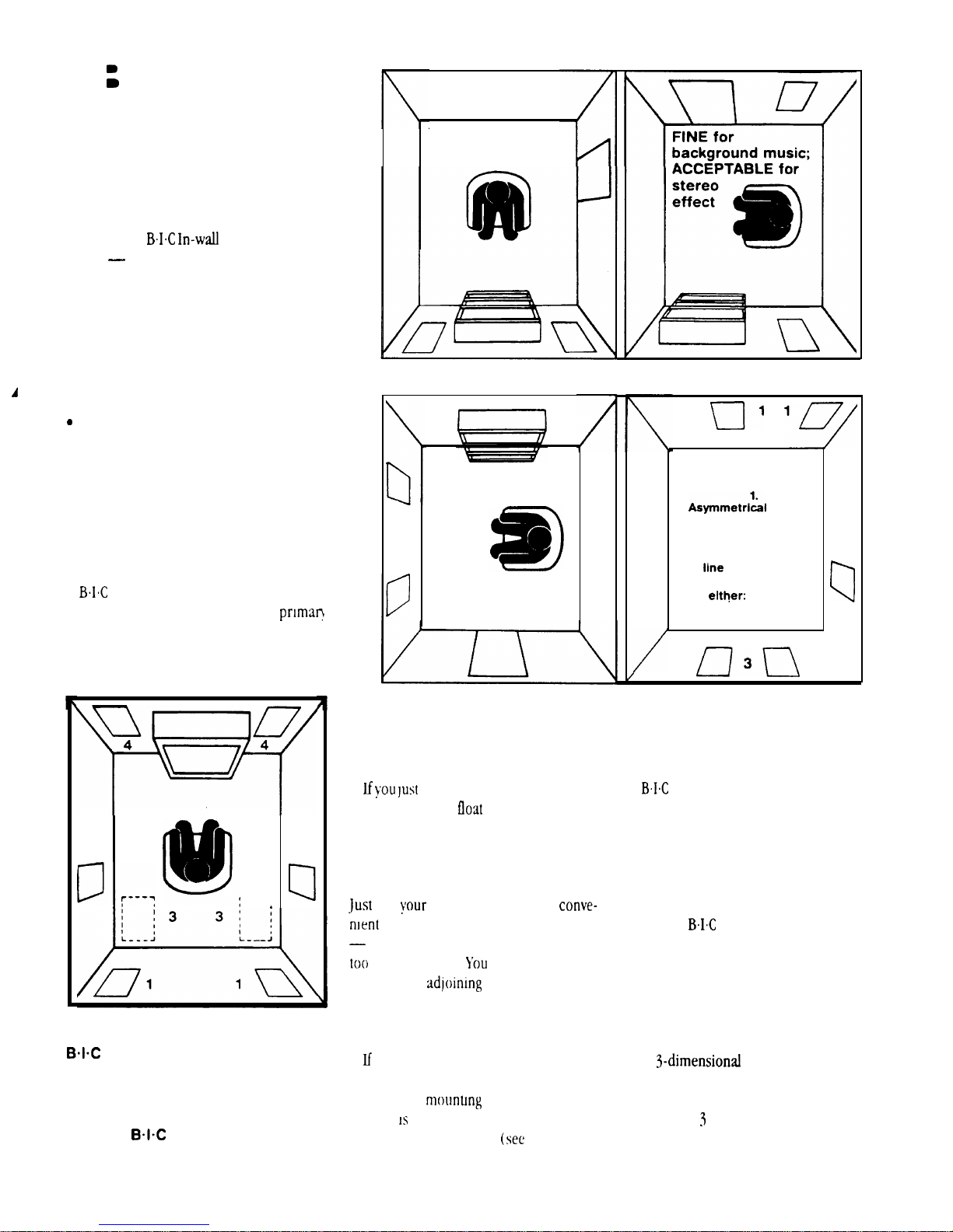
In-Wall Speakers can be
used for background music, as a
listening system or as built-in rear
surround speakers in an audio/video
home theater.
2
c----
DRAWING 2
in-wall speakers may be used
for rear surround sound channels
by placing them (1) behind, (2) on
each side of the viewing position or
(3) in the ceiling just behind the
viewers.
make excellent, unobtrusive front
channel home video theater speakers (4).
In-wall speakers also
2
I
EXCELLENT
for stereo imaging
DRAWING 3
Background music
want low-volume background music to
placement for best acoustics and imaging
is not particularly critical. You can pretty
well ignore all our diagrams and tips on
imaging and other acoustical matters.
put
speakers where it’s
and non-intrusive to room decor
but without grouping both speakers
close together
speakers in
living room that flows into a formal dining room, or in a kitchen and breakfast
nook.
you’re going to place the speakers
high up on a wall, flip the speaker upside
down when
tweeter
on the bottom. This will insure
better treble dispersion
through a room,
can even place the
rooms, such as a
it so that the
Drawing 4).
OK for background
music; not good
for stereo imaglng
cl
2
Surround sound
surround sound speakers. They can be
mounted at ear level in any of the positions shown in Drawing 2 including from
the ceiling.
STEREO IMAGING
If your
going to be your primary listening source
in a room, you need to consider some
other factors to insure proper imaging.
The term “stereo imaging” refers to a
speaker system’s ability to project music
so that it sounds like the performers are
in a
speakers. It’s the whole point of having a
stereo instead of monophonic system.
Drawing
ments as well as some situations to avoid.
response; more bass
from right speaker
Both speakers aren’t
in line wlth listener
Not recommended
for either:
Too close together
2.
3.
2
\
In-Wall Speakers make excellent
In-Wall Speakers are
space between the
shows some possible place-
Page 5
rotated
down
OTHER ACOUSTIC
CONSIDERATIONS
For best fidelity, there are several
other factors to keep in mind before you
start actual installation.
Vertical placement
Treble frequencies are quite
directional.
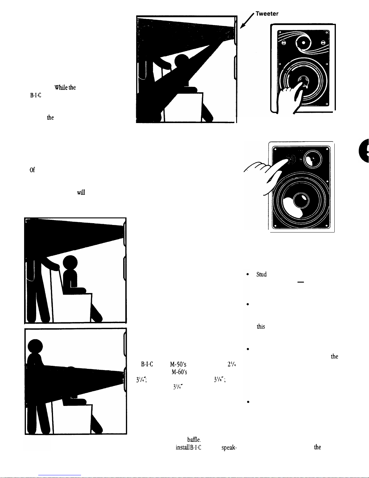
dome tweeters
in
Muro M-50, M-60 and M-80
speakers are designed to disperse high
frequencies over a wide area, they will
give you
best sound when positioned
so that they are at least at ear level, as
shown in Drawing 4.
If you have M-8.3’s or VI-38’s, the
tweeter can be swivelled to direct the
high frequencies toward the listening
position. See drawing 4A.
installed in an area where listeners usually stand up (such as a kitchen or
hallway), “ear level”
be higher on
the wall than for rooms where listeners
are often seated.
DRAWING 4
DRAWING 4A
Corners and reflections
When an in-wail speaker is placed
close to the comer of a room, bass
frequencies are emphasized. This can
be OK if both speakers are mounted
near comers (while maintaining stereo
imaging). But try to avoid placing just
one speaker in a corner and another on
a long flat wall.
Treble is emphasized when it
reflects back from reflective surfaces
such as large windows. Conversely,
highs tend to be muffled by soft
surfaces such as drapes, rugs,
upholstered furniture, carpeted steps
and even textured fabric wall paper.
In general, the best acoustic
performance will result if both speakers
face a similar type of surface and are
placed in similar positions on the same
type of wall.
WALL AND CEILING
SURFACES
Now that we’ve covered where you
should put your speakers, let’s consider
where you CAN put them.
Muro
require at least
of wall depth;
require at least
M-80 and M-8.3’s require
VI-38 requires
of wall depth (all
measured from the outside surface of
the wall).
This means that they can be installed in
any wallboard-and-2x4 stud wall. In fact,
the dense, rigid nature of plasterboard
(or lath and plaster in older homes) acts
as a superb speaker
You can also
In-wall
VI-38
Push on rim of
tweeter to rotate
M8.3
ers in stud walls covered with thick wood
paneling or in wallboard/plaster ceilings.
However, avoid:
walls covered only with thin
veneer paneling
the surface
isn’t rigid enough and can cause
annoying vibrations and buzzing.
T-bar “drop ceilings with very
thin fiberboard panels which can
buzz and vibrate. If you suspect
will happen, reinforce the’
drop-in panel with wood or particle
board.
Any wall which can’t provide
proper depth (clearance) for
back of the Muro speaker to
protrude. This includes brick or
concrete walls where the
wallboard or paneling is attached
to thin furring strips.
Walls where you know that there
are pipes, heating ducts and
ESPECIALLY AC wiring in the
general vicinity. For example, if
there is an outlet along the
baseboard, there is often a live
wire running partly up
wall at
Page 6
SPEAKER WIRE PATHS
The last consideration is the obstacle
course that lies between the speakers’
hoped-for mounting positions and your
stereo system.
Wires can be run through crawl spaces
that lie above your ceiling or below the
floor, through basements or second
stories, or simply along the perimeter
of your listening room. We cover each
of these options in detail in the
“Running connecting wires”
section
attention to the following areas:
l
l Make sure that the entire path
l
of this manual.
general, you should pay particular
Avoid running speaker wires close
to house electrical wiring for any
distance. If you have to run them
parallel, make sure to space the
speaker wires at least two feet from
the AC line. It is, however, OK for
speaker wires to cross paths with AC
line or go through the same hole
together with house wiring if they
separate before and after.
between speakers and amplifier is
clear and not obstructed by a major
floor or ceiling joist or masonry wall
which you won’t be able to drill
through.
Remember that the other end of the
wires has to come out somewhere
to connect with the amplifier.
Confirm ahead of time that you can
drill an outlet hole easily and in an
unobtrusive spot.
PAINTING YOUR
CUTTING HOLES
FOR THE
If you like the designer
which has been applied to your
In-Wall Speakers, you can skip to Step D,
next column. But if you want your speakers to completely blend in with a colored
wall or accent the surface, now is the
time to paint your
outer frames and perforated grilles.
The speaker’s outer surfaces are
primed to accept ordinary latex wall paint
or aerosol spray paint. Because the surface behind the perforated grille should
remain black, you will need to mask this
area off before you begin painting.
01.
First the speakers’ grille must be
removed, From the back of the
speaker, insert a mounting screw
and push on the
to loosen it so you can pull it off.
Attach loops of
double-stick tape to the cardboard
masking cards which have been
included with your speakers.
Press a masking card onto each
03.
speakers’ surface to cover the
woofer and tweeter.
04.
Paint the outer speaker frame and
grille separately. A roller with a
short or medium nap will work
much better than a brush. If you’re
using spray paint, make sure that
you achieve the same coverage on
both grille and frame.
After the paint has thoroughly
dried, remove the cardboard
masking plate.
There’s no need to replace the grille at
this time since you will need access to the
inner speaker surface during installation.
In-wall speakers’
finish
of the grille
tape or
SPEAKERS
to make a relatively neat hole. Actually,
the hole doesn’t even have to be that neat,
since the speaker’s outer frame will cover
it. Just make sure you don’t make it any
bigger than the template. In the following
steps, you’re going to locate a section of
wall between two studs, mark the outer
boundaries of the hole, drill a small hole
in the center to co&rm your
location and then cut the main hole.
01.
02.
Wallboard is an easy surface in which
First you must determine the
location of your wall studs so that
the speaker can be approximately
centered between them. There are
several ways to go about this:
l Tap on the wall and listen to
the resulting “THUMP”. When it’s
deeper, you’re between studs.
When it’s sharper and more
sounding, you’re close to a stud.
l Use a stud-finder, a simple little
magnetic device which works by
locating the lines of nails hammered into the stud.
l Identify studs by the position
of electrical outlets or switches,
There’ll be a stud either directly to
the left or right of an electrical
fixture. This gives you a point of
measurement, since studs are
either 18 or 16 inches apart in
newer houses,
homes.
When you’re reasonably sure of
where the wall stud 2x4’s are
(and are TOTALLY sure that there
isn’t an electrical cable, water pipe
or heating duct in that vicinity of
inches apart on
Page 7
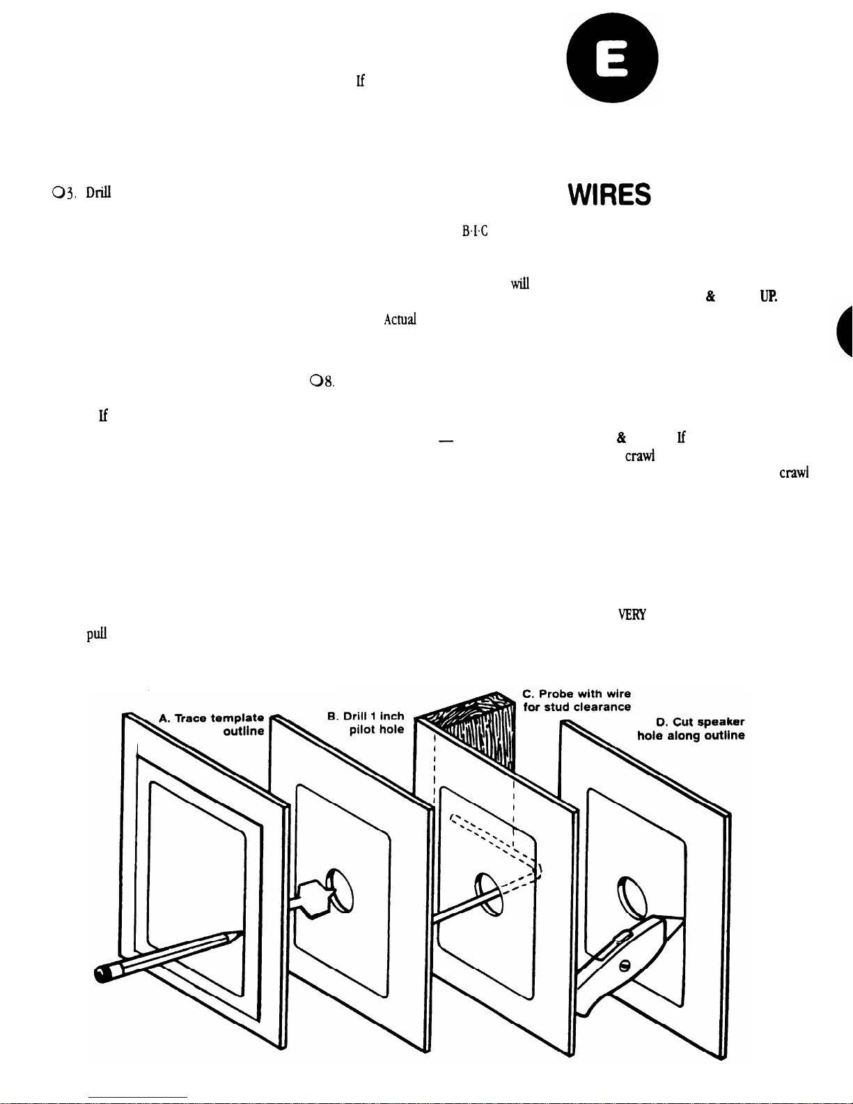
wall), position
one of the card
board mounting templates and
draw around the inside outline
with a pencil. If you don’t trust
your eye, use a level to make sure
the hole will be straight.
Repeat for the other speaker position.
a l-inch hole in the center of
the pencil outline which you have
just drawn.
obtain a length of stiff wire such as
04.
an unwound, totally un-bent coat
hanger, Bend it so that the last 12
inches is at a right angle to the rest.
Insert the angled part into the
05.
l-inch hole you just drilled and
probe to left and right to confirm
that a stud is not close on either
side.
l
there is a close stud on one
side, just re-position the cardboard
template a few inches in the
opposite direction and re-draw
your pencil outline, keeping the
l-inch hole within the pencil out-
line’s inner boundaries.
06.
If there are no obstructions, cut
the hole along the pencil outline. If
the surface is wallboard, simply cut
it increasingly deeper with a utility
knife until it gives way and then
it out by grasping the cut-out
through the l-inch hole.
l
you’re dealing with lath and
plaster or thick paneling, you need
to use a different technique. Drill
l-inch holes at the comers of the
pencil outline. Then use a keyhole
saw or even a hacksaw blade with
VERY slow strokes to saw through
and remove the inner surface.
Temporarily place a
07.
In-wall
speaker into the cut-out to insure
that it fits properly. It’s OK if the
hole is slightly large, since it
be covered by the. speaker’s outside
frame.
installation will happen later, after you’ve routed the
speaker wires.
Repeat steps 1 through 7 for the
other speaker.
Now it’s time to drill the hole on
09.
the OTHER end
at the point
where the wires from the speakers
will exit to the amplifier/receiver.
l Use the same l-inch drill bit as
before.
l If you want a totally finished job,
install an outlet box against a stud
and cover it with a TV cable or
single outlet plate which has one
hole in the middle for the wires to
exit from.
RUNNING
CONNECTING
Now you know were the wires have to
run. It’s time to actually route
mentioned before, there are several
sibilities.
1. DOWN, ACROSS
you
have a crawl space under your house
or a relatively unfinished basement,
your job is broken into three parts:
1) Down from the amplifier to the crawl
space; 2) Across the crawl space to the
wall(s) with the speakers; 3) Up the wall
to the speaker.
2.
UP
OVER.
overhead
you
space, your three steps
are: 1) Up from the amplifier to the
space; 2) Across the crawl space to the
wall(s) with the speakers; 3) Down the
wall to the speaker.
3. OVERLAND. If the speakers and
amplifier are in the same room and it is
carpeted, you can route the wires along
the baseboard. This method results in
just two
short lengths of wire being
possibly visible.
them. As
pos-
BACK
If
have an attic or
DRAWING 5
Page 8
Use whichever method (or combination) is most applicable, but read each
over before undertaking it.
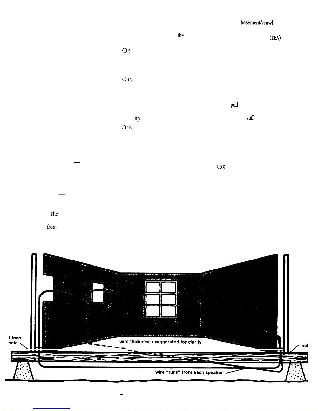
DOWN, ACROSS AND
BACK UP (BASEMENT OR
LOWER CRAWL SPACE)
If you have an unfinished basement or
crawl space under your home, you can
avoid having to run wires in the room.
Working from underneath is sometimes
trickier since there are often more pipes,
ducts, electrical and cable lines already
0
in place.
01.:Make sure you have the following:
0 Tape measure
0 Cordless drill (or regular
model with long extension cord)
with a l-INCH BIT
0 A VERY long roll of speaker
wire
0 Wire cutters
either diagonal
pliers or wire strippers which
include a cutting surface
0 Length of stiff wire such as coat
hanger at least 3 feet long
0 Tape
any kind will do
0 It’s also convenient to have
another person upstairs helping
you.
person’s job will be to
grab the cables as you push them
up
below.
02.
Enter the basement or crawl space
and proceed to a spot directly
below where one of
in-wall
speakers will be.
After carefully measuring to make
sure you’re in the right place, drill
a hole up through the horizontal
2x4 directly below the speaker.
If you haven’t encountered in-wall
insulation (sometimes present on
outside walls), have your assistant
drop a plumb bob or weight string
down until you can reach it. Tape
the cable to it and let them pull it
there’s another approach: Get out
your long roll of speaker cable and
tape the end to the stiff wire or
bent coat hanger. Push the stiff
wire with speaker cable attached
up through one of the holes far
enough that your assistant can
grasp it through the speaker cut-
out above. Have him or her pull
out at least 8 feet of cable (as
measured from your position
downstairs).
05
Making sure that the end doesn’t
get pulled back down through the
hole, reel out wire while moving
across the basement.&& space until
you reach a location below the amplifier,
06.
07.
08.
Extend at least
10
extra
feet
of cable and cut the end off the
roll.
Grab your coil/roll of cable and
move over to the hole that’s been
drilled below the other speaker.
Again, have your assistant drop a
plumb bob or weight and string
down until you can reach it. Tape
the cable to it and let him or her
it up, extending at least 8 feet
of wire up through this hole. Or
use the
wire method if the
wall has insulation or obstructions
in it.
Making sure the end doesn’t get
pulled back down through the
hole, reel out cable until you reach
the space under the amplifier.
Extend at least
10 (TEN) extra
feet
of cable and cut the end off the
roll. You’ve now run wires from
both speakers to a point directly
below where the amplifier will be.
l-inc
DRAWING 6
DOWN, ACROSS AND BACK UP
Page 9
Drill a l-inch hole through the
010.
horizontal 2x4 directly below the
amplifier wall outlet hole.
Because of the small diameter of
011.
the hole, the plumb bob/string
method may not work on the
amplifier end. If so, tape the two
cable ends (which come from the
speakers) to a stiff wire and push
them up through the hole. Since
there’s only a l-inch hole upstairs,
you’ll probably need to wiggle the
wire around until your helper can
locate it and snag the wires taped
to the end. They, too may need to
use a length of stiff wire with a
hook in it to grab the cables
through the small hole.
Have your helper pull the cable
up until most of the slack has
been taken up down in the crawl
space or basement. If you want,
you can secure the cable runs to
the floor joists or beams using
insulated staples.
You’ve done it! Skip to the next section
titled
“Hooking up your speakers.”
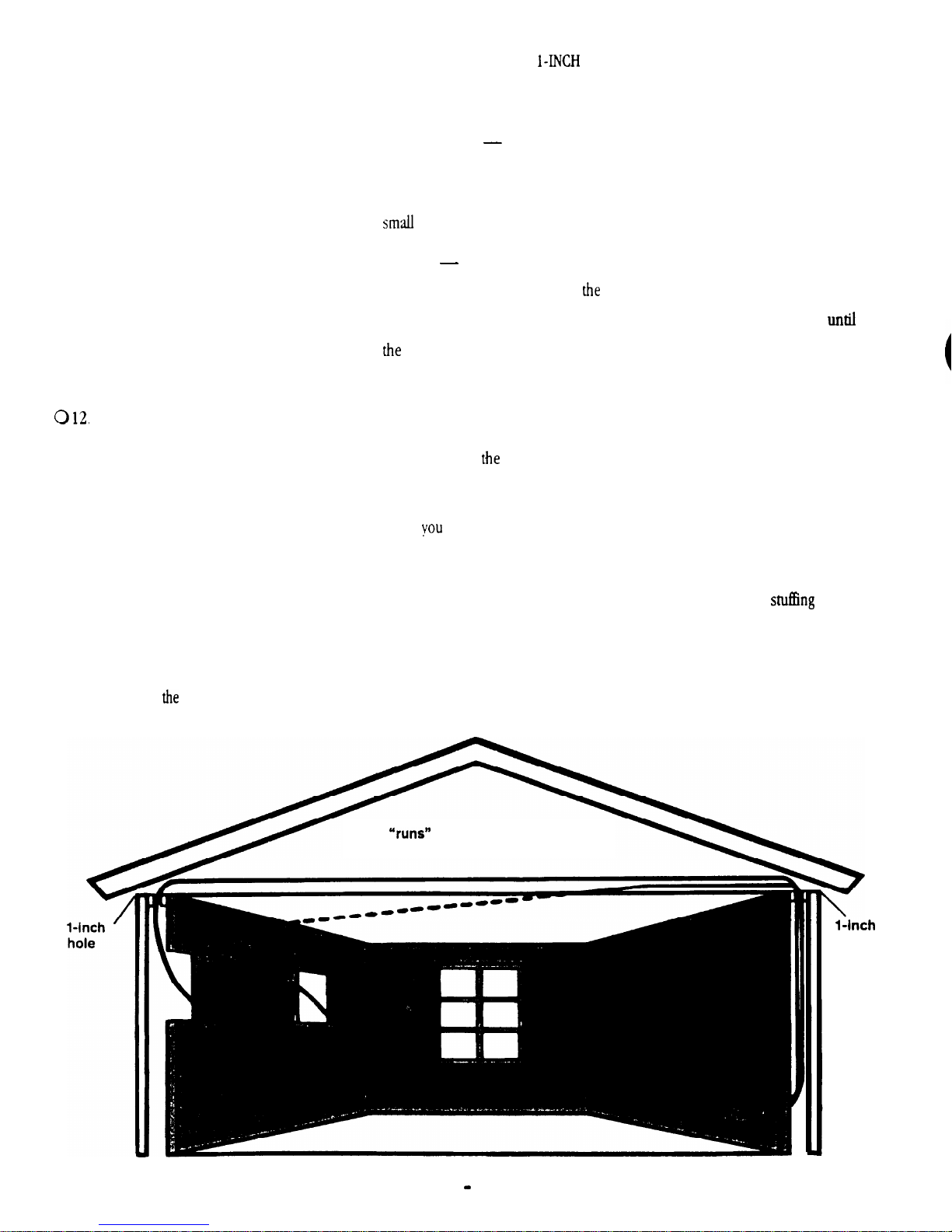
UP AND OVER
(ATTIC CRAWL SPACE)
0 Tape measure
0 Cordless drill with a
BIT
(or non-cordless model with
long extension cord)
0 A VERY long roll of speaker wire
0 Wire cutters
either diagonal
pliers or wire strippers which
include a cutting surface.
0 Plumb bob or string with a
weight (such as a metal nut)
on the end
0 Tape
Crawl up into the attic with all
02.
any kind will do
aforementioned stuff and proceed
to a spot that’s directly over one of
speaker cut-out holes.
After carefully measuring to make
03.
sure you’re in the right place, drill
a hole through the horizontal
2x4
directly ABOVE the SPEAKER. Then
drill a hole for
04.
Time to use that roll of cable. Push
other speaker.
the cable end through one of the
holes
just drilled until it
extends at least 8 feet. If you
encounter insulation, such as an
outside wall, tape the speaker cable
to a stiff wire and poke it down
until it can be located at the
speaker cut-out.
reel out cable while moving across.
the attic/crawl space until you
reach the location above your
amplifier.
06.
Extend at least 10 (TEN) more feet
of cable for the roll and cut it.
Grab your coil/roll of wire and
07.
move over to the hole that’s been
drilled above the other speaker.
Extend at least 8 feet of wire down
through this hole
08.
Again, making sure that the end
doesn’t get pulled back up through
the hole, reel out cable
reach the space above the amplifier.
Extend at least 10 (TEN) more feet
09.
of cable and cut it. You now have
cables running from both speakers.
Time to get them down the wall to
where the amplifier will be.
010.
Drill a l-inch hole through the
horizontal 2x4 directly above the
amplifier wall outlet.
011
Now you’re going to guide cables
down to where they’ll emerge
from the wall. Since this hole isn’t
very big, just
them down
and grabbing them won’t work.
you
0 1. You’re about to ascend into your
attic. Grab
following:
Making sure the end doesn’t get
05
pulled back up through the hole,
wire
(thickness exaggerated
from each speaker
for
clarity)
hole
DRAWING 7
UP AND OVER
Page 10
Instead, it’s time for the plumb
bob or string-with-weight (or wire
if there’s insulation to contend
with). Tape the two cable ends
(which come from the speakers)
to the plumb bob string just above
weight and lower the whole
thing down through the I-inch
hole above
probably have to “feed out” the
attached cable to get the weight to
descend.
Continue “paying out” both
012
cables until they and the weight
hit bottom.
plumb bob string to something so
that it doesn’t fall down the hole.
013
014
attic crawl space and
stretch for a moment.
Go over to the l-inch amplifier
wire hole and look for the
extended string/plumb bob and
attached cables. If they’re not
visible, fish around for them with
your
and pull them through the hole.
Then rescue the plumb bob from
the attic.
amplifier. You’ll
the free end of the
coat hanger
OVERLAND
If, for a variety of reasons, it’s
impossible to route cables above or
below, you can still achieve a relatively
invisible job, assuming your amplifier
can be located in the same room. The
only visible cable will be a
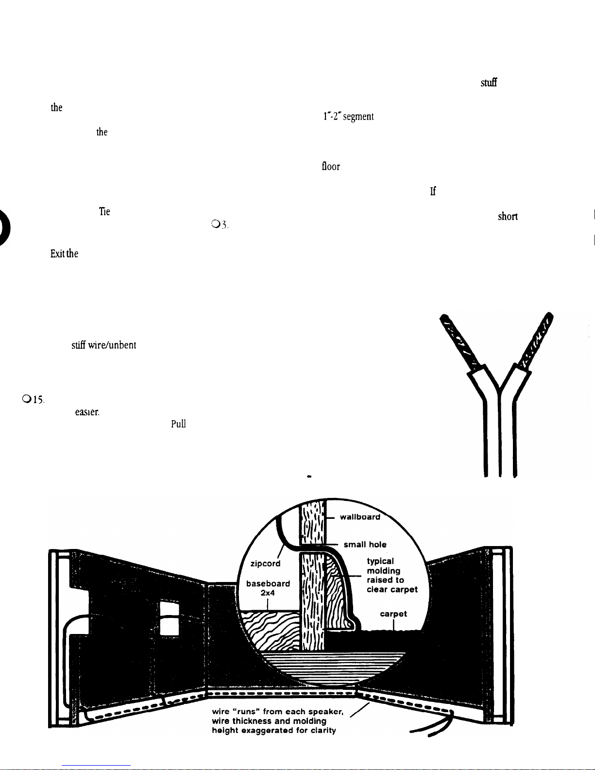
on the baseboard below each speaker.
01.
On the wallboard directly-below
each speaker cut-out hole, measure
up 2 inches from the
mark the spot with a pencil dot.
02.
Drill a small hole just large enough
to admit a speaker cable.
Insert one end of your speaker wire
through the small drilled hole and
use a stiff hooked wire to fish out
the speaker cable from above.
Repeat for both speakers.
04.
When a room is carpeted, the
baseboard moldings are elevated
slightly to clear the carpet and pad.
This creates a hollow space
and
between the bottom of the molding
and the floor which can be used to
conceal your speaker cable along
the perimeter of the room. Use a
screwdriver to
until you reach the spot where your
amplifier will be.
To secure the cable so that it
05
doesn’t get pulled out during
vacuuming, add insulated staples
at the points where the cable enters
and exits the baseboard.
Note:
normal, you can drill the hole behind the
baseboard and avoid the
visible cable. You may have to chisel a
shallow channel in the back of the baseboard for clearance.
your baseboards are taller than
the cable under
length of
DRAWING 9
At the speaker holes, things are
much
through and grab the cables.
their whole free length out the cut
speaker hole. You’ve done it! Skip
to the next section, titled
*‘Hooking up your speakers.”
You can just reach
DRAWING 8
OVERLAND
Page 11
HOOKING UP
AT
THE SPEAKER END
01.
The main thing to remember when
hooking up speakers is
the two
conductors in
speaker wire are not
interchangeable. One
be used as a
POSITIVE (+) conductor and
other
as a NEGATIVE
conductor. These
correspond to
RED
and BLACK
(-) connectors on your
Muro
Wall Speakers and also to the speaker
terminals on your amplifier or receiver.
IDENTIFYING
and
You need to be able to discriminate
between the two conductors in
zip
cord.
your wire has transparent insulation,
this is easy: One conductor will be copper-colored and the other silver-colored.
Generally, professionals denote the copper one as POSITIVE (+) and
silver
one as NEGATIVE
you’ve used wire
has an
opaque insulation, there are
differen-
tiating
wire close-
ly and look for:
l A series of ribs or grooves on
one conductor
Make sure that
the speaker wire
Is passed
THROUGH the
mounting bracket
before connection
\
01.
02.
03.
04.
05.
06.
l A painted stripe
l A single strand of yarn inter-
twined with the multi-stranded
wire in one conductor.
Denote any of these as the
POSITIVE (+) conductor for
similar connections on both ends.
Cut off excess wire, leaving about 2
feet extending through the speaker
cut-out hole.
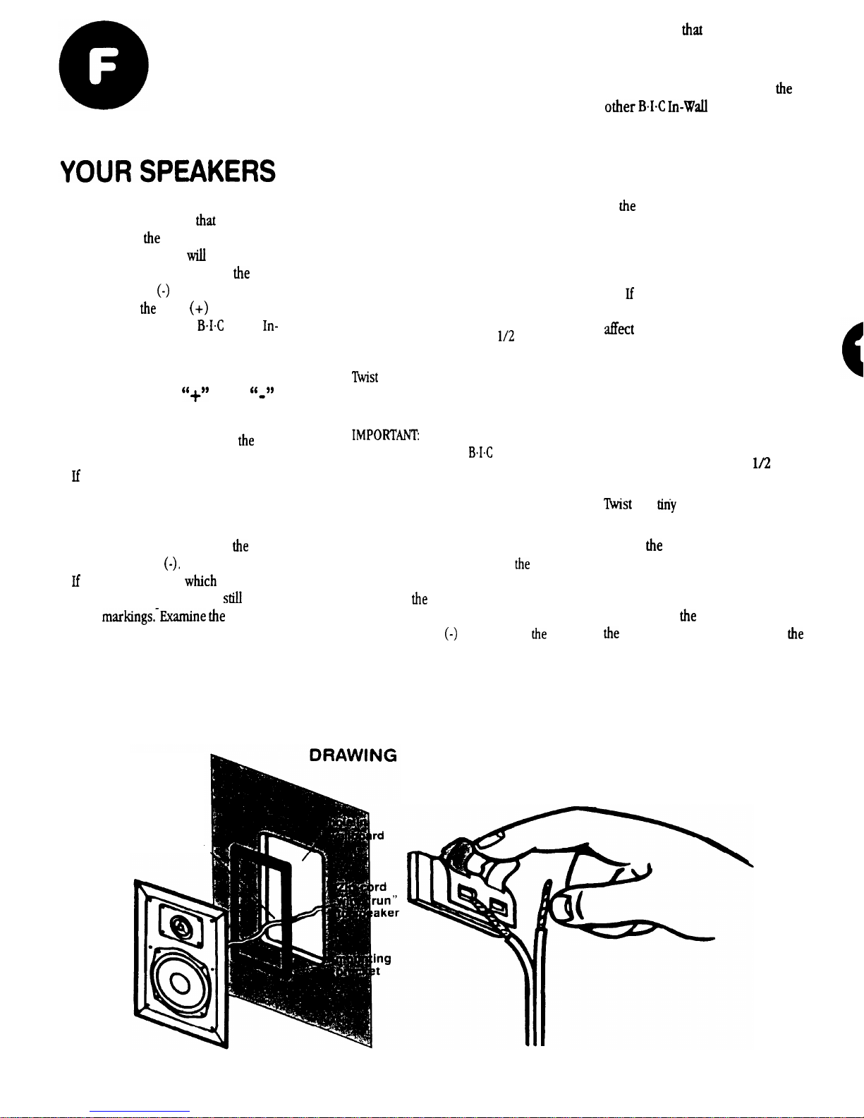
Pull the conductors apart so
they’re separated for the first two
inches from their ends.
Using wire strippers, diagonal
pliers or a knife, remove l/2 inch
of insulation from each conductor.
the tiny strands in each
conductor into tight spirals, as
shown in Drawing 9.
Route the speaker
wire THROUGH the
In-wall
speaker frame as shown in
Drawing IO.
Attach the speaker wires to the red
and black speaker terminals. Press
down on the protruding levers
while inserting the wire into
hole.
l Connect
POSITIVE (+)
conductor to the RED terminal and
the NEGATIVE
conductor to
BLACK speaker terminal.
07.
l Make sure
no stray strands
of wire have gotten detached and
are touching the other main wire.
Repeat Steps 1 through 6 for
BIG
Speaker.
AT THE AMPLIFIER END
02.
03.
04.
05.
Cut off excess wire, leaving enough
to comfortably reach from the hole
in
wall to your stereo system. If
there’s a possibility that you’re
going to move the amplifier to
another part of the room, consider
leaving some excess wire coiled
up.
you’ve used sufficiently thick
wire, this extra length will not
speaker performance and
could make things easier if the
room is rearranged later.
Pull the conductors on both
speaker wires apart so they’re
separated for the first two inches.
Using wire strippers, diagonal
pliers or a knife, remove
inch
of insulation from each conductor.
the
strands in each
conductor into tight spirals.
Attach
speaker wires to the red
and black speaker terminals on the
amplifier or receiver.
l Connect the POSITIVE (+)
conductor to
RED terminal and
NEGATIVE (-) conductor to
BLACK speaker terminal.
l Make sure that no stray strands
of wire have gotten detached and
are touching the other main wire.
10
Page 12
FINAL ASSEMBLY
0
If you haven’t done so already
05.
02
03
during painting, remove the perforated grilles from both
Muro
Speakers, Use one of
the black mounting screws to push
the grille out from the back side.
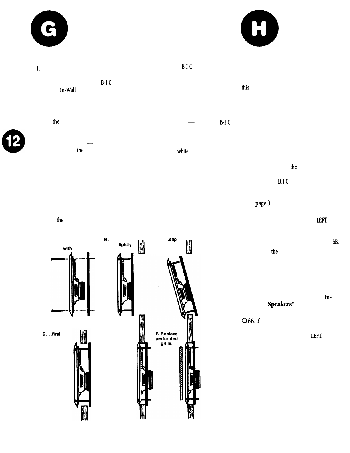
Attach the black mounting bracket
to
speaker using the black
screws provided, as shown in
Drawing 11. Tighten the screws just
a few turns each
only enough to
loosely hold
mounting bracket
in place.
NOTE: Although six holes are
provided on both the speaker and
bracket, only four are used.
Slide the bottom of the bracket
inside the speaker cut-out hole,
followed by the top so that the
wallboard is between the bracket
and
speaker.
A. Attach mounting
With screws
bracket to speaker
4 screws
only
threaded...
.
the bottom,
then the top.
04.
06.
Center the speaker in the cut-out
hole and tighten the screws until
the mounting bracket is drawn up
snugly from behind, clamping the
speaker in place. Try to tighten
each screw equally.
Replace the
Muro speaker
grille by gently pressing it into
place.
Repeat the above steps for the
other speaker.
In most situations, the grilles will Et
tightly without vibration. If any audible
vibration does occur
or if your
In-wall speakers are ceiling-mounted,
you finally get to use the contents of that
mysterious packet with the black stuff
wrapped in little
papers, They’re
pre-cut lengths of a special
damping/adhesive material,
Remove the perforated grille, unwrap
four of the damping strips and affix them
to the four outer comers of the inner
speaker surface. Then replace the grille.
E. Tighten
all 4 screws
evenly.
c. .
the bracket
behind the
wallboard..,
A SHORT TEST
DRIVE
It’s a good idea to test everything out at
point. Also, although we’ve paid close
attention to speaker polarity, we haven’t
concerned ourselves with which wires
went
01.
02.
03.
04
05.
06.
to left and right speakers.
Turn on your stereo system. Make
sure that the VOLUME control is
turned down and that the BALANCE
control is set to center.
Activate a musical source such as
FM, a tape or CD player.
Gently turn up
volume. You
should hear music coming out of
your new
In-Wall Speakers!
(If you don’t, refer to the
troubleshooting guide on the next
Now rotate the stereo’s BALANCE
control all the way to the
Sound should only come out of
your left speaker. If it comes out of
the RIGHT speaker, skip to Step
Rotate
BALANCE control all the
way to the RIGHT. Sound should
only come out of the right speaker.
If this is the case, your installation
is a success. We suggest you read
the section on the next page titled
Taking care of your new
wall
(for further
operating tips).
sound comes from the right
speaker when the stereo’s balance
control is turned to the
you’ll
need to change the connections on
the back of the amp or receiver.
l
FIRSTTURNOFFTHE
AMPLIFIER!
l Then swap the wires attached to
the left and right speaker terminals.
DRAWING
11
Page 13

A QUICK
Before returning your
Speakers for service, it’s
check out these simple remedies
from either speaker
1.
Incorrect source selected on
receiver or
2.
Mute button pressed on receiver.
Wrong speaker output selected
3.
many receivers have an “A” and
speaker switch. Make sure it’s
in the right position.
No
S
from one speaker
1.
Un-secure connection
speaker
check them.
Balance control turned
left or right
Bad connecting cable between
sound
a new cable.
Defective speaker
Intermittent sound from one speaker
or speakers play initially but then
shut off.
1.
Short circuit’at either the
amplifier or speaker connectors is
activating the amp’s protection
circuits
connections, making sure no stray
strands of wire
are touching the ‘other.
or
return it to center.
source
dealer or call
and amplifier
double check
In-Wall
good idea to
either the
double
the way
try
contact your
348-6492.
one connector
Both speakers play but sound is
mixed with hum.
1.
It could be a faulty patch cord. If
so, there will be hum from your
main speaker system as well as
from your
2.
Assuming you didn’t have hum in
your system before, one or both of
the speaker wires has been run too
close to internal AC house wiring.
Re-route it so that it stays at least 2
feet away from AC power wiring
when running parallel.
Both
speakers play but sound is
muffled and “strained”. Amplifier
may shut off if volume is raised too
far.
1.
Too thin a gauge of wire has been
run too far a distance between amp
and speakers. Make sure that you
have followed our suggestions as to
wire gauge versus overall distance.
(M-60, M-80, M-8.3, Vl-38 only)
When volume is turned up to a high
level, the treble cuts in and out
1.
The M-60, M-80, M-8.3 and VI-38
feature a special protection circuit
which electronically disconnects the
tweeter if it starts getting too hot.
Turn down your amplifier and make
sure to read the section of this
manual titled
your new in-wall speakers”
which starts on this page.
‘Taking care of
Speakers.
FURTHER
READING
TAKING CARE OF YOUR
NEW IN-WALL SPEAKERS
In-Wall Speakers are designed to
last the life of your home
a few simple rules.
The main “killers” of any loudspeaker
system are 1) too
volumes, 2) too much power at high
volumes, 3) transient thumps.
Not enough power
a surprising fact, but far more
speakers are damaged by too little
power than by too much! When an
amplifier runs out of power while trying
to re-create musical peaks, it causes a
form of high frequency distortion called
clipping. In moderate amounts,
clipping simply makes the music sound
terrible. In greater quantities over a
period of time, it can damage or destroy
the tweeters (high frequency reproduction speakers) in any speaker system. If
you like your music LOUD, consider
getting an amplifier with
watts per channel.
Too
much power
There’s nothing wrong with driving
your
as 150 warts per channel
power helps them achieve quick
musical transients found in digital
recordings. However, you must
remember to restrain yourself and not
get too heavy-handed with the volume
control (or remote buttons).
music begins to sound distorted or you
hear a “cracking” sound during bass
notes, back
M-60, M-80, M-8.3 or VI-38 internal
protection circuits are intermittently
shutting off the tweeter, you’re exceeding
its safe power input level.
In-wall speakers with as much
And naturally, if the
if you follow
power
least 60
the extra
the
high
Page 14

robust receivers and power amplifiers
may even allow two sets of 4-ohm
Loud, deep THUMPS, caused when you
speakers.
turn your stereo on or off, or when the
is dropped too hard on a
record, can seriously damage any loudspeaker including your
In-Wall
information, consult the dealer where
you purchased the amplifier, or call the
manufacturer.
models. It’s always a good practice to
turn the volume down (or press the
MUTE button if your receiver has one)
when changing records or selecting
another source (such as changing from
other speakers. It’s often printed on the
back of the enclosure down near the connection terminals, or you can consult the
speaker’s owners manual.
tuner to CD player input). Also remember
to
your system off before disconnecting any hook-up cables. When they’re
pulled out, a huge burst of low frequency
hum often occurs if the system is still on.
8 ohms impedance. In general, this
means that most amplifiers will allow
you to simultaneously operate one set of
Muro In-Wall Speakers and one other set
of
Cleaning
Muro In-wall Speakers.
M-50, M-60, M-80, M-8.3 and
VI-38 speakers are covered with a
durable finish which can be cleaned
with soap and water or spray cleaners.
Avoid the use of ammonia-based cleaning
ohms, some amplifiers may experience
difficulty driving both sets at once and
shut off intermittently when the volume
control is turned up.
products, however. If you’ve painted the
grills and frames, follow the paint
manufacturer’s cleaning instructions.
MORE ON AMPLIFIERS
one set of speakers at a time or keep
the volume extremely low.
Parallel operation
AND IMPEDANCE
Not all amplifiers or receivers can
safely operate two sets of speakers at
once. If you intend to use your
Wall Speakers at the same time as your
main speakers
hook up two pairs of
or if you intend to
In-Wall
Speakers and use both at the same time,
it’s important to consider both the impedance of the speakers and the capabilities
of the
you’re using.
First, consult the owner’s manual
that came with the amp or receiver. It
should tell you
minimum speaker
impedances during simultaneous
operation. On some models, the
manual will recommend that only two
pairs of
speakers be used at the
same time. Others might allow one set
of
speakers and one set of 4-ohm
impedance speakers. A few extremely
connected in parallel create a
load. This means that some amplifiers
can be used to drive as many as four sets
of
(or three sets and one pair of main lis-
tening room speakers).
The following chart may be used as a guide:
SIMULTANEOUS SPEAKER OUTPUT
OUTPUT RATING
Two sets of
One
Two
If you can’t readily determine this
Next, determine the impedance of your
All
speakers are rated at
loudspeakers
or two sets of
If your other speakers are rated at 4
In this case, you should operate only
sets
of
speakers
In-Wall speakers at the same time
AMPLIFIER
A
spkrs.
set, one
sets spkrs.
set
1 pr BIC In-Wall speakers
1 pr BIC In-Wall speakers
1 pr BIC In-Wall speakers
1 pr. BIC In-Wall speakers
2 prs of BIC In-Wall speakers
2 prs. BIC In-Wall speakers
INSTALLING
MURO
SPEAKERS DURING NEW
CONSTRUCTION
Needless to say, installing
speakers when a house is being built is
far easier than doing it later.
offers a “Speaker Rough-In Kit”
which consists of four brackets and a
molded speaker mounting frame. The
brackets are nailed onto wall studs and
then the mounting frame is attached.
During new installation, keep the fol-
lowing tips in mind:
Use a bubble level to verify that
the mounting frame is straight.
The flat brackets and nails which
attach them are thin enough that
they won’t interfere with wallboard
added later.
possible run speaker wires after
AC wiring is in place to avoid
induced hum caused by close
parallel proximity.
Secure speaker wires in place along
the run with insulated staples only
and be careful not to pierce the
insulation.
expansion of building materials.
Needless to say, the actual
speakers should not be installed
until the wall
the meantime, leave several feet of
wire coiled up and secured to the
back side of the mounting frame.
AND
AND
AND 1 set
OR
AND 2 prs. of BIC In-Wall speakers
AND 1 set
OR
AND 2
pr. BIC In-Wall speakers
a bit of slack for
board
is in place. In
SPEAKER OUTPUT
B
1 set
speakers
speakers
speakers
of BIC In-Wall speakers
Page 15
l
it comes time to put up the
dry wall, make sure the speaker
cut out hole doesn’t extend farther
than
from the sides of the
mounting frame.
l
After the wallboard is put up,
install the speakers as detailed on
page 11 of
manual.
M-50, M-60, M-80,
M-8.3 AND VI-38
DESCRIPTIONS AND
SPECIFICATIONS
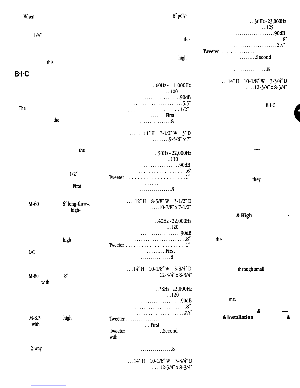
M-50, M-60, M-80, M-8.3 and
VI-38 have been ruggedly constructed to
withstand not only
range found in today’s digital sound
sources, but also the rigors of temperature
variation, dust and moisture encountered
in permanent installation. Above all, they
have been designed to give you
possible music reproduction possible in
modest-sized speakers.
The M-50 features a 5.5” long-throw,
polypropylene woofer and 1/Z
ferrofluid-cooled dome tweeter. A
mylar capacitor is used in a
crossover configuration to prevent low
frequencies from entering the tweeter.
The
employs a
polypropylene woofer with
compliance foam surround to achieve
additional bass response. The l-inch,
ferrofluid-cooled soft dome tweeter
achieves excellent transient response
and wide dispersion of
frequencies. An advanced, Second
Order
crossover uses air-core
inductors and premium mylar
capacitors for enhanced sonic
performance.
The
employs an
core woofer
coil. The l-inch soft dome tweeter fea-
tures a ferrofluid-cooled high tempera-
ture voice coil. An advanced custom
designed crossover features built-in self
resetting tweeter protection.
The
woofer
features a
vented pole piece and rubber
surround for maximum bass reproduction It has a coated cone midrange for
greater mid frequency detail compared to
typical
designs. It also employs a
titanium dome swivel tweeter for superb
high frequency reproduction and precision aiming.
extreme dynamic
finest
Order
polycarbonate
high temperature voice
power
The Venturi VI-38 features a
carbon woofer with rubber surround for
outstanding base reproduction. It
employs a 2.5’ poly cone midrange for
accurate mid-range reproduction. At
heart of the VI-38 is a concentric mount-
VI-38
Frequency response
Max. recommended power
Sensitivity
Woofer . . . . . . . . . . . . . . . . . . . . . .
Midrange
ed 1” pivoting titanium tweeter for precise
imaging and aiming of the critical
frequency range.
Specifications
M-50
2
watts
Order
ohms
Frequency response
Max. recommended power
Sensitivity
Woofer
Tweeter
. , , . , . ,
Crossover type
Impedance
Crossover type
with level attenuator for mid and tweeter
Impedance
Dimensions
Overall
Required cut-out
product quality as new technology and
techniques become available,
America reserves the right to revise
speaker systems specifications without
notice.
Dimensions
Overall
Required cut-out
x
M-60
Frequency response
Max. recommended power watts
Sensitivity
Woofer
Crossover type
Impedance
Second Order
Dimensions
Overall
Required cut-out
X
M-80
Frequency response
Max. recommended power
Sensitivity
Woofer
Crossover type
Impedance
Dimensions
Overall
Required cut-out
x lo-l/s”W x
M-8.3
Frequency response
Max. recommended power
Sensitivity
Woofer
Midrange
Crossover type
. 1” swivel
Order Woofer
and Midrange
level attenuator for tweeter and
midrange.
Impedance
Dimensions
Overall
Required cut-out
x
ohms
X
Order
ohms
ohms
x
x
watts
watts
Order
OUTSIDE HELP
undertaking installation
start it and for some reason can’t finish
you have several alternatives for outside
help.
contractors.
specialize in complete “turnkey” installs,
many stereo installation
also willing to do hourly work
Unfortunately, they’re buried in the listings with
Stereophonic
Dirs),
phone calls to find one.
With
company, a whole new industry has
sprung up. These people are experts at
stringing wires unobtrusively and have the
tools to do the job quickly and easily.
Many advertise
papers or even via signs on bulletin
boards.
Larger companies which specialize in
installation
Pages under the following listings:
Telephone Equipment
Wiring
Television Cable Contractors. These
firms charge more than free-lance
installers but are also easier to locate and
contact.
and
use a true electrical contractor. They’re
listed in the
watts
x lo-l/s”W x
. 1’ Pivotal
Order
ohms
Due to our continual efforts to improve
If you don’t feel that you’re up to
or if you
1. Custom stereo installation
Although
prefer to
companies are
regular stereo dealers (under
Fidelity Equip
so you may have to make several
2. Free-lance telephone installers.
deregulation of the phone
community
3.
Phone installation services.
be found in the Yellow
Systems
4.
Electrical contractors. As
or Telephone
a last
expensive resort, you can always
Yellow Pages under
Electric
Contractors.
 Loading...