

Page 1

Wall hung, fan flue, room sealed, high efficiency gas boiler
Service manual
RIVA ADVANCE HE
Models: G.C. Appl. No.
M110B.24SM/C 47---583---11
M110B.32SM/C 47---583---12
M110B.24SR/C 41---580---07
Leave this manual adjacent to the gas meter
Page 2

Tab l e of co n te n t s
1 Overall information 1..................
1.1 Overall View 1.........................
1.2 Hydraulic diagram 1....................
2 General access and emptying hydraulic
2.1 Nomenclature 2........................
2.2 Body panels 2.........................
2.3 Control panel 2........................
2.4 Access to the sealed chamber 3.........
2.5 Emptying the primary circuit 3...........
2.6 Emptying the d.h.w. circuit 4............
3Diagrams 5...........................
3.1 Wiring diagram
3.2 Wiring diagram M110B.24SR/... 6........
3.3 Circuit voltages 7......................
4Faultfinding 8........................
5 Condensing heat exchanger 10..........
5.1 Function 10.............................
5.2 Removal 10............................
5.3 Cleaning 11............................
6 D.h.w. heat exchanger 12...............
6.1 Function 12.............................
6.2 Removal 12............................
7Pump 13...............................
7.1 Function 13.............................
7.2 Checks 13.............................
7.3 Removal 13............................
8 Three way diverter valve 15.............
8.1 Function 15.............................
8.2 Checks 15.............................
8.3 Removal of the electric actuator 15........
8.4 Removal of the diverter group and its
9 Electronic control/ignition p.c.b. 17......
9.1 Function 17.............................
9.2 Selection and adjustment devices 17......
9.3 Checking the temperature 18.............
9.4 Operation lights 19......................
9.5 Setting the boiler control function modes 19
9.6 Adjustment of maximum useful output
9.7 Reignition frequency setting 20...........
9.8 Combi / C.H. only mode setting 21........
9.9 Checks 22.............................
9.10 Removal of the electronic control p.c.b 22..
9.11 Thermal control in the ”
9.12 Thermal control in the ”
10 Transformer 26.........................
10.1 Removal 26............................
10.2 Check the transformer 26................
11 Gas valve 27...........................
11.1 Function 27.............................
11.2 Description of the parts 27...............
circuits 2.............................
M110B.24SM/... M110B.32SM/... 5.......
internal parts 16.........................
in c.h. mode 20.........................
”mode 24......
”mode 25......
11.3 Adjustment 27..........................
11.4 Checks 28.............................
11.5 Removal of the gas valve 28..............
12 Primary circuit flow switch 30...........
12.1 Function 30.............................
12.2 Checks 30.............................
12.3 Removal 30............................
13 Expansion vessel and
temperature--pressure gauge 31........
13.1 Function 31.............................
13.2 Checks 31.............................
13.3 Removal of the expansion vessel 31.......
13.4 Removal of the temperature ---pressure
gauge 31...............................
14 D.h.w. flow switch, filter and flow limiter 32
14.1 Function 32.............................
14.2 Description and location of parts 32.......
14.3 Checks 32.............................
14.4 Removal of the sensor 32................
14.5 Removal of the flow switch group
and d.h.w. circuit filter 32.................
14.6 Flow limiter 32..........................
15 Temperature probe 34..................
15.1 Function 34.............................
15.2 Checks 34.............................
15.3 Removal of the c.h.Temperature probe 34..
15.4 Removal of the d.h.w.Temperature probe 35
16 By--pass valve 36......................
16.1 Function 36.............................
16.2 Removal 36............................
17 Fan and Air box 37.....................
17.1 Function 37.............................
17.2 Removal of the Air box and the Fan 37.....
18 Ignition and detection electrodes,
burner and spark generator 38..........
18.1 Function 38.............................
18.2 Removal of the Ignition
and detection electrodes 38..............
18.3 Removal of the burner 38................
18.4 Removal of the front insulation panel 39....
18.5 Removal of the rear insulation 39..........
18.6 Removal of the spark generator 40........
18.7 Checks 40.............................
19 Safety thermostat 42...................
19.1 Function 42.............................
19.2 Checks 42.............................
19.3 Removal 42............................
20 Flue temperature probe NTC
and Safety thermal fuse 43..............
20.1 Function 43.............................
20.2 Removal 43............................
20.3 Checks 43.............................
21 Condensate trap 45....................
21.1 Function 45.............................
21.2 Check the cleanness of the trap 45........
21.3 Removal 45............................
22 Short spare parts list 46................
Page 3
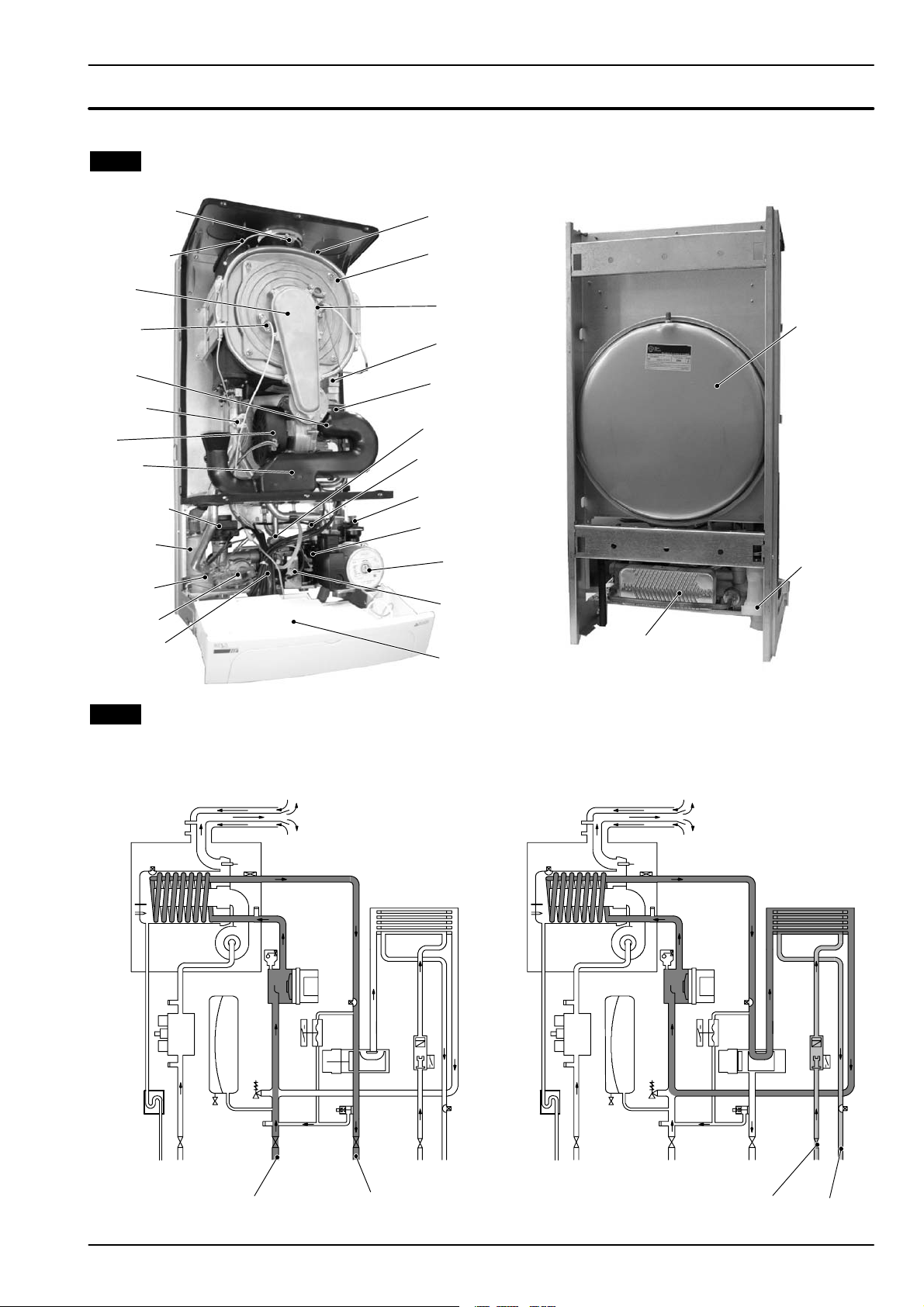
1 Overall information
1.1 Overall View
Flue temperature
probe NTC
Condensing heat
exchanger air
purger valve
Burner
Detection
electrode
Air box
Safety
thermostat
Fan
Air hose
Diverter valve
Codensate
trap
C.h. temp.
probe
Main circuit
flow switch
D.h.w. temp .
probe
Safety thermal
fuse
Condensing
heat exchanger
Ignition
electrodes
Spark
Generator
Transfor mer
Gas restrictor
C.h. pressure
relief valve
Automatic
air purger
valve
D.h.w. Flow
Switch
Pump
Gas valve
Control
panel
D.h.w.
heat exchanger
Expansion
vessel
Condensate
trap
1.2 Hydraulic diagram
Central heating (c.h.) operation
Domestic hot water (d.h.w.) operation
C.h.
water return
C.h.
water flow
D.h.w.
inlet
D.h.w.
outlet
1
Page 4
2 General access and emptying
hydraulic circuits
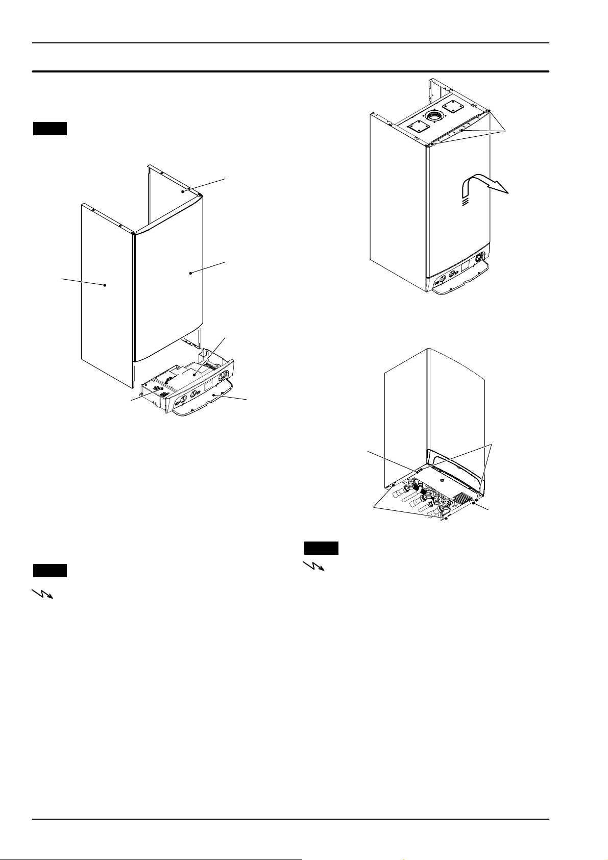
2.1 Nomenclature
6
5
A
1
2
Fig. 2.2
To remove the side panels loosen the screws B and C
3
(Fig. 2.3), bring the base of the panels away from the
boiler and lift them, freeing them from the top hooks.
4
Fig. 2.1
1 Right side panel
2 Front panel
3 Control panel lid
4 Control panel cover
5 Service panel
6 Left side panel
2.2 Body panels
Warning: isolate the boiler from the mains
electricity supply before removing any
covering or component.
For the most part of the check and maintenance operations it is necessary to remove one or more panels of
the case.
The side panels can be removed only after the removal
of the front panel.
To remove the front panel remove screws A (Fig. 2.2),
lift the panel and remove it.
B
C
Fig. 2.3 --- bottom view of the boiler
D
B
2.3 Control panel
Warning: isolate the boiler from the mains
electricity supply before removing any
covering or component.
To gain access to the parts located inside the control
panel proceed as follows:
1 Remove the front panel of the case.
2 Loosen the screws B and C (Fig. 2.3).
3RemovethescrewsD.
4 Move the lower part of the side panels as indi-
cated in Fig. 2.4 and pull the control panel.
When completely pulled out, the panel can rotate
45˚ downwards to facilitate the service operations on the internal parts.
2
Page 5
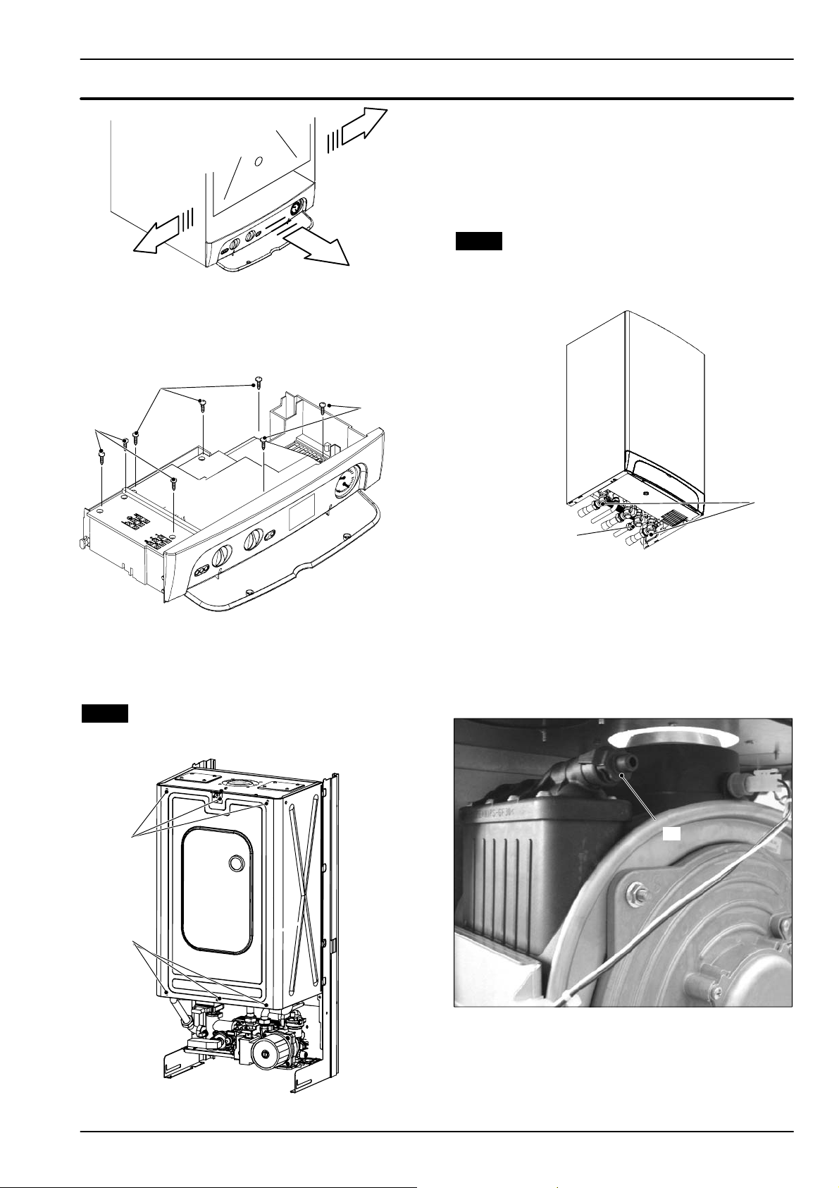
Fig. 2.4
5RemovethescrewsE and remove the service
panel (Fig. 2.5).
F
F
E
General access and emptying hydraulic circuits
To gain access to the parts contained in the sealed
chamber it is necessary to remove the lid of the s ealed
chamber.
For this purpose, remove the front and side panels of
the case, remove the screws G as indicated in Fig. 2.6
and remove the lid.
2.5 Emptying the primary circuit
1 Close the c.h. circuit flow and return cocks H.
(Fig. 2.7).
Fig. 2.5
6RemovethescrewsF andremovethecontrol
panel lid (Fig. 2.5).
2.4 Access to the sealed chamber
G
H
K
Fig. 2.7 --- bottom view of the boiler
2 Remove the front and right panels of the boiler.
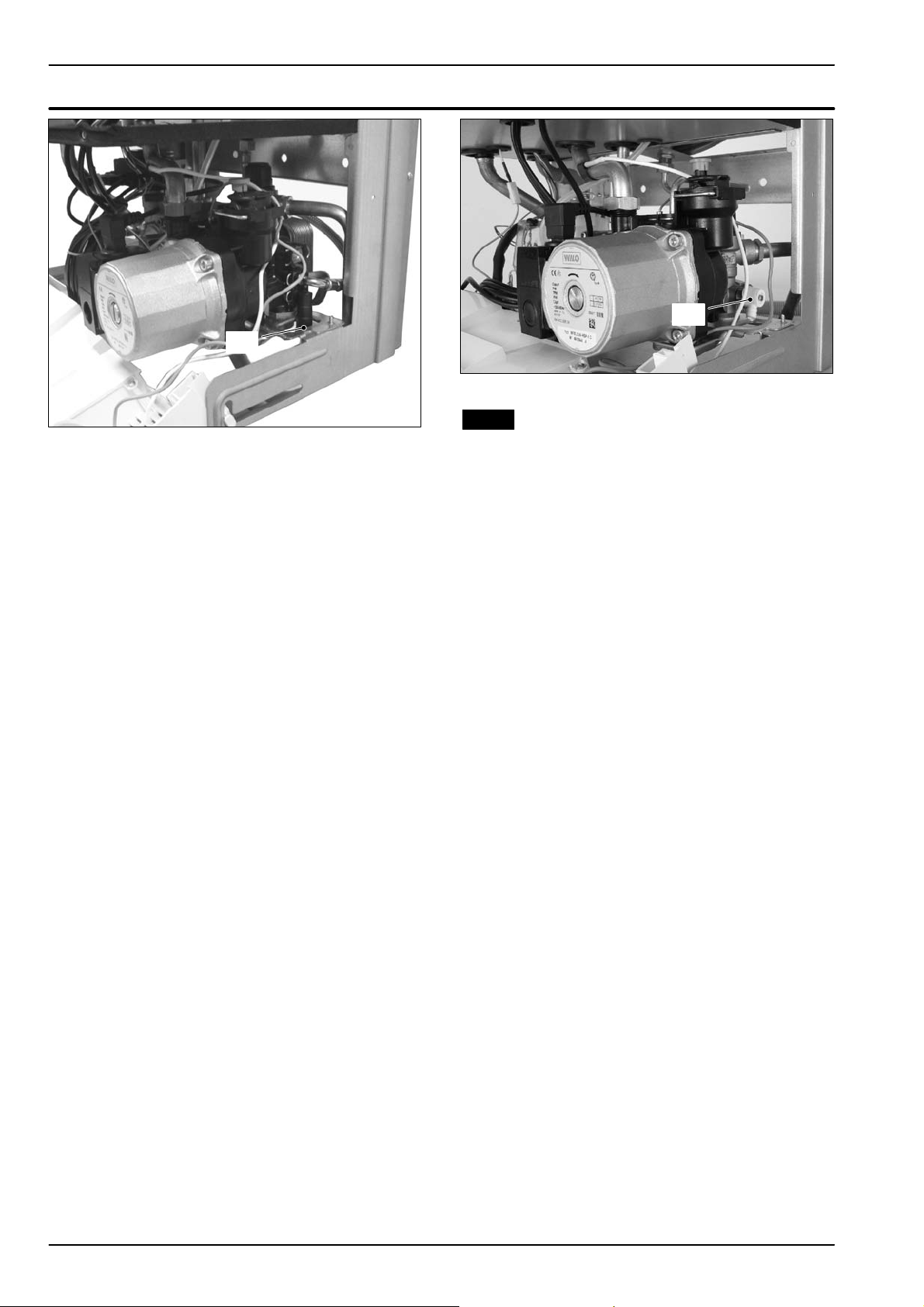
3 Open the drain tap I (Fig. 2.9 combi or Fig. 2.10
only c.h.) until the boiler is completely emptied.
4 To help t he draining of the primary circuit loose
the condensing heat exchanger air purger valve
J (Fig. 2.8).
J
Fig. 2.6
G
Fig. 2.8
Attention: some water could remain in the condensing heat exchanger.
5 Close drain tap once the emptying has been
completed.
3
Page 6
General access and emptying hydraulic circuits
I
Fig. 2.9
I
Fig. 2.10
2.6 Emptying the d.h.w. circuit
6 Close the d.c.w. inlet cock K (Fig. 2.7).
7 Open one or more hot water taps until the boiler
has been completely emptied.
4
Page 7
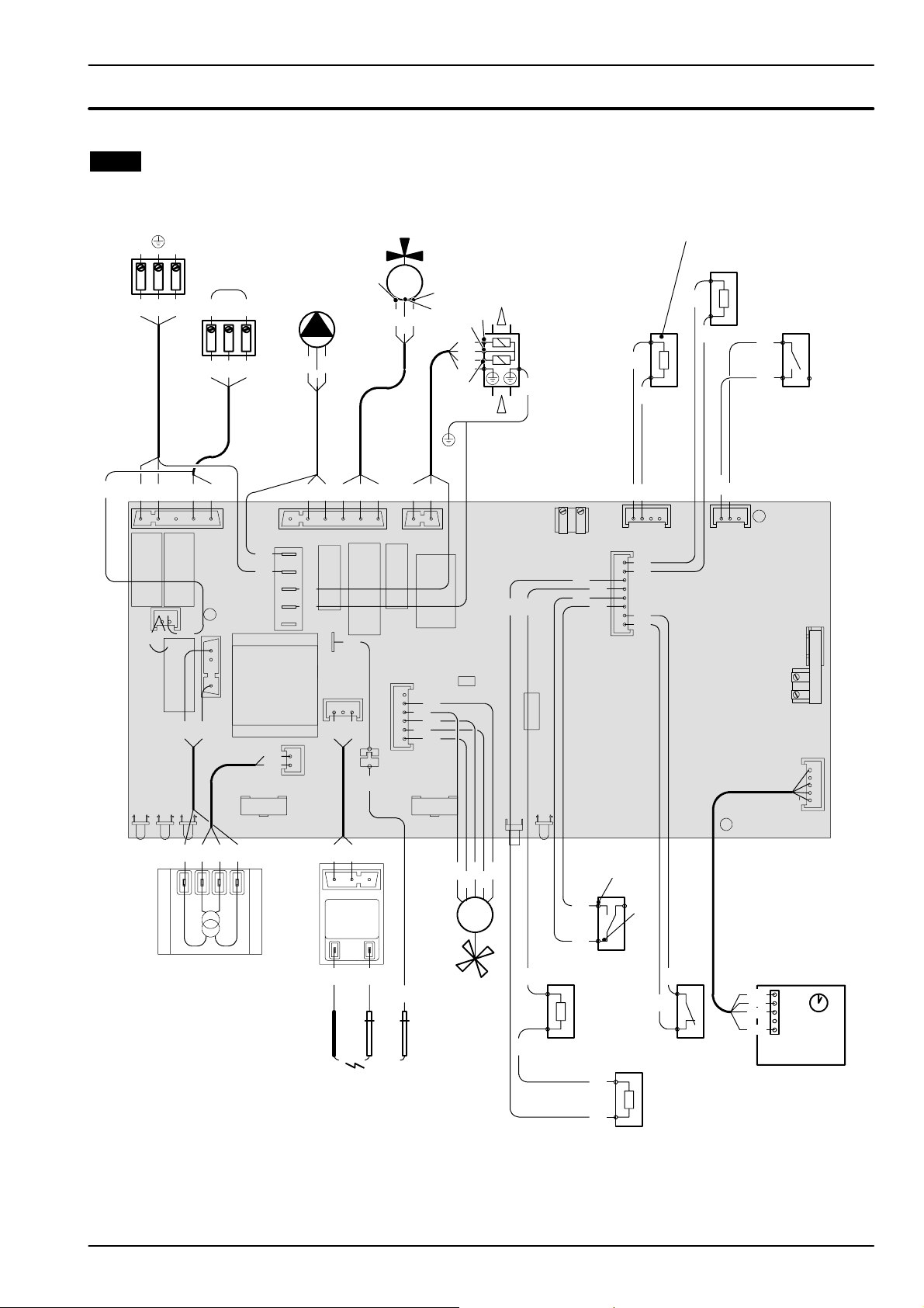
3 Diagrams
3.1 Wiring diagram
M110B.24SM/... M110B.32SM/...
Electric supply
terminal block
LN
External controls
terminal block
bn
gnye
bu
bkbu
Three way
diverter valve
1
M
3
2
Gas valve
1
4
bu
bn
bu
gnye
5
gnye
123
bn
Pump
gnye bu
bn
~
rdbkwh
D.h.w. temperature
probe NTC
C.h. temperature
bu
bk
t
rd
probe NTC
t
bu
D.h.w. flow
switch
bu
wh
bn bu
bn bk bu
F1F2
X16
bn
whwh
F3
bu bn
LD1LD2LD3
Transfor mer
230V~ / 24V~
bn = brown
bu = blue
bk = black
wh = white
rd = r ed
gy = grey
gn = green
ye = yellow
vt = violet
og = orange
gnye = green/yellow
rdwh = red/white
Safety
wh
bu
X10X11
X13
X2
rd
bk
wh
gn
Time switch
rd wh bk
bnbu
X12
bububnbn
gnye
gnye
X3
T3
bu
bn
P6
Generator
Ignition
electrodes
gnye
K3
gnye
gy
X15
X6
bu bn
X24
bn bu
Spark
X7
X5
bu bn
X14
X17
K1
wh
whog
K2
K4
X22
rd
bk
bu
gy
wh
P3
bk
wh
Flame detection
electrode
X23
Fan
X1
LD4
Primary circuit
t
Flue
rd
rd
rd
flow switch
bkwh
SB1
rd
gybuwh
M
~
bk
gy
temperature
probe NTC
wh
bk
rd
NO
gy
wh
Safety
thermal fuse
bk rd
bu bu
gy
gy
X9
COM
gy
gy
thermostat
t
5
Page 8
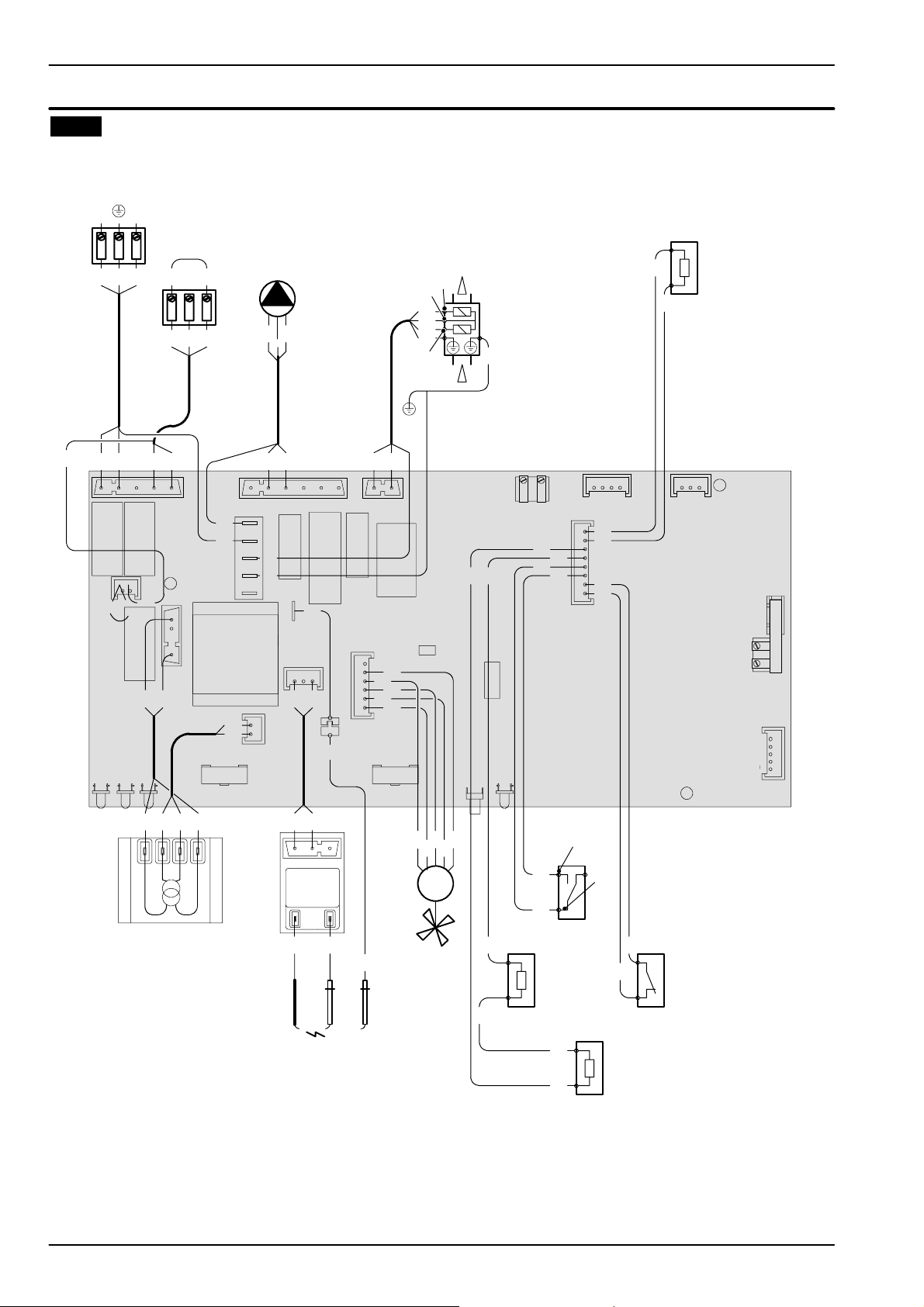
Diagrams
3.2 Wiring diagram
M110B.24SR/...
Electric supply
terminal block
LN
External controls
terminal block
bn
gnye
bu
bn bu
bn bk bu
123
bkbu
bn
Pump
gnye bu
bn
bnbu
bu bn
Gas valve
1
4
bu
bn
bu
gnye
5
gnye
C.h. temperature
probe NTC
bu
t
bu
X7
F1F2
X16
bn
whwh
F3
X5
bu bn
LD1LD2LD3
Transfor mer
230V~ / 24V~
bn = brown
bu = blue
bk = black
wh = white
rd = r ed
gy = grey
gn = green
ye = yellow
vt = violet
og = orange
gnye = green/yellow
rdwh = red/white
bububnbn
X12
gnye
gnye
X3
T3
bu
bn
P6
Generator
Ignition
electrodes
X14
X17
gnye
gnye
X24
K3
X15
X6
bu bn
bn bu
K1
gy
wh
K2
K4
X22
X23
rd
bk
bu
gy
wh
P3
bk
bkwh
SB1
rd
gybuwh
Spark
M
~
whog
wh
Flame detection
Fan
electrode
bk
gy
temperature
probe NTC
X1
LD4
Primary circuit
t
Flue
wh
rd
rd
rd
flow switch
gy
wh
bu bu
bk
rd
gy
gy
X9
NO
COM
t
Safety
thermal fuse
gy
gy
thermostat
X10X11
X13
X2
Safety
6
Page 9
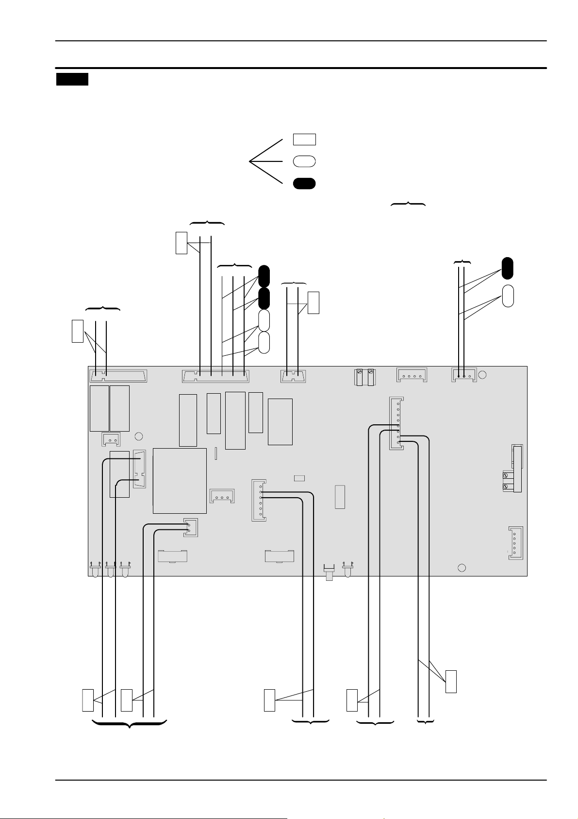
3.3 Circuit voltages
Diagrams
during c. h. or d.h.w. operation
Electrical voltages with burner on
Pump
230~
Supply network
230~
X12
X7
F1F2
X3
X16
T3
F3
X5
3way
diverter valve
K1
K3
X15
X6
only during c.h. operation
only during d.h.w. operation
D.h.w.
Flow switch
Gas valve
230~
230~ 0230~0
X14
X17
K2
K4
X9
X22
X23
X1
X10X11
0
5=
X13
230~
LD1LD2LD3
24~
Transfor mer
X24
24=
P3
Fan
SB1
LD4
0
Main circuit
pressure switch
Safety
thermostat
0
P6
X2
7
Page 10
Pressure gauge
--- ---
(7)
Components to check
Safety valve
Expansion vessel
Flue temperature probe NTC
Gas restrictor
Safety thermostat
Detection electrode
Ignition electrode
Spark generator
Fan air restrictor
B y --- p a s s v a l v e
D.h.w. temp . p robe
Main circuit temp. probe
D.h.w. filter
Main circuit flow switch
Gas valve
Boiler settings
Electronic p.c.b.
Fuses (Electronic p.c.b.)
J J J J J
J J J J
J J
D.h.w. flow switch
Diverter valve
Pump
6 7.2 8.2 9.9 11.4 12.2 14.5 15.2 16 17 18.7 18.7 19.2 19.2 20.1 ---
(4)
21.1 ---
---
(3)
---
(2)
(1)
10 ---
D.h.w. heat exchanger
D.h.w. circuit
C.h. circuit
Condensate drain pipe and trap
Flue pipes
Gas supply line
J J J J J J J J J J
Power supply line
Transfor mer
J J J J J J J J J J J
J J J J
J J J J J
J J J J J
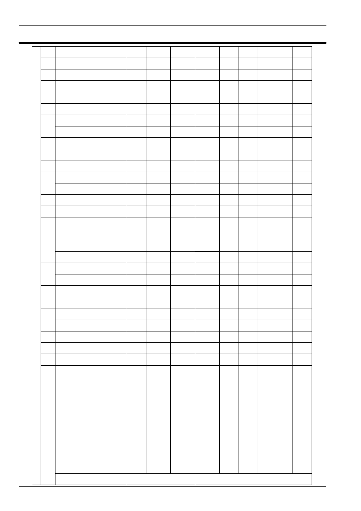
Defect
4 Fault finding
#
Section of the manual !
(note ref. in brackets)
By pressing the reset push--- button
the boiler turns on and operates cor-
rectly.
By pressing the reset push--- button
the boiler starts the ignition cycle.
The b urner doesn’t light on and the
boiler locks again.
By pressing the reset push--- button
the boiler starts the ignition cycle.
The b urner lights on and the boiler
The boiler does not start either in c/h
or d.h.w. mode.
All the operation lights OFF
Fan still.
The b urner doesn’t light either in c.h.
or d.h.w. mode.
Fan turns.
The b urner doesn’t light either in c.h.
or d.h.w. mode.
Fan doesn’t turn.
The b oiler doesn’t control the d.h.w.
temperature.
Turning the d.h.w. temp. adjustment
knob hasn’t effect on the modulation
of the flame.
The boiler operates correctly on c.h.
The boiler lights for a short while on
c.h.
locks again.
L o c k --- o u t s i g n a l l a m p r e d
ON
Normal operation on d.h.w. function.
OFF
8
Page 11
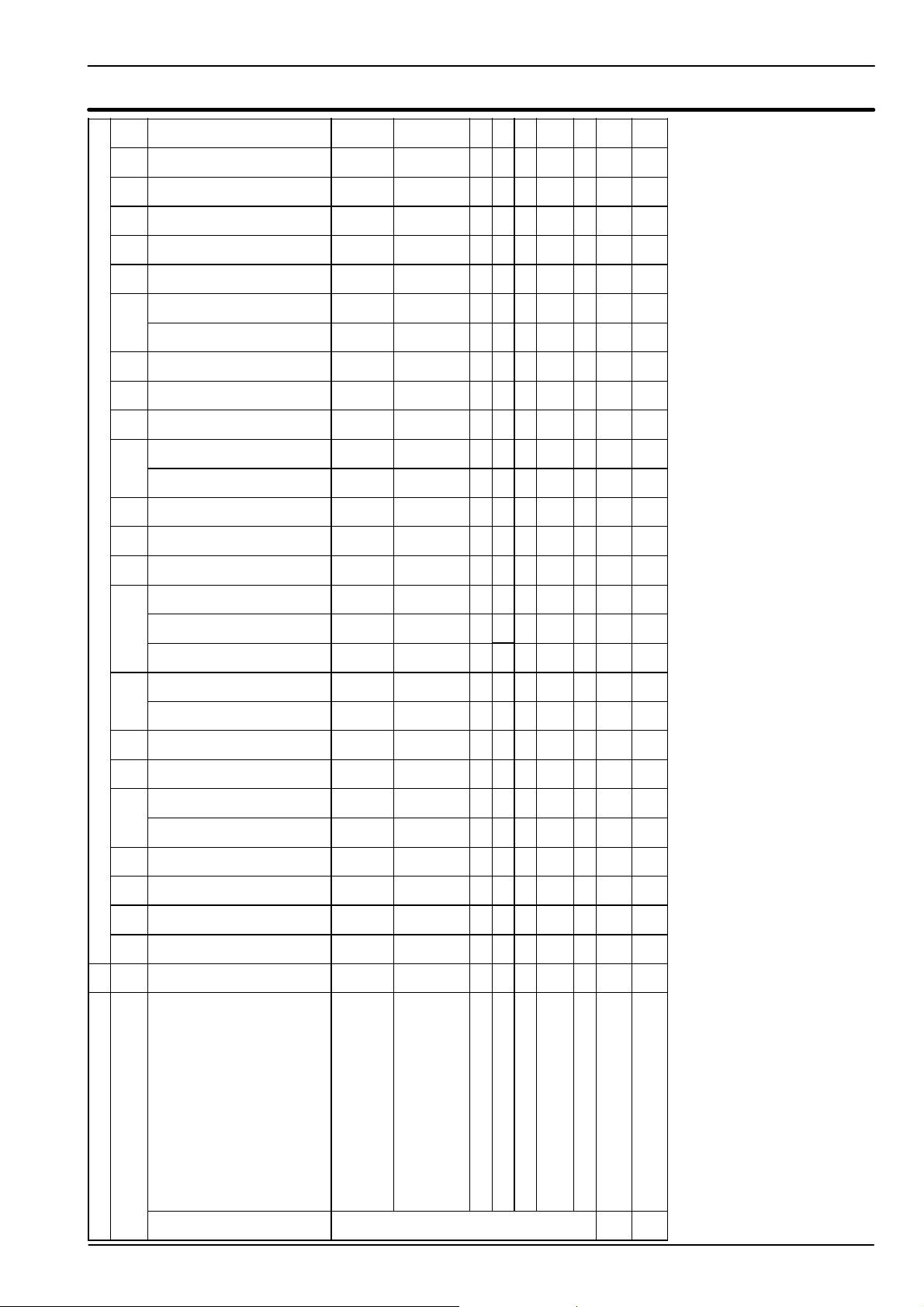
---------
F
(7)
20.119.219.218.718.7171615.214.512.211.49.98.27.26---
Pressure gauge
Safety valve
Expansion vessel
Flue temperature probe NTC
Gas restrictor
Safety thermostat
Detection electrode
Ignition electrode
Spark generator
Fan air restrictor
B y --- p a s s v a l v e
J J
value of the flue gases.
2
D.h.w. temp . p robe
Main circuit temp. probe
D.h.w. filter
Main circuit flow switch
Gas valve
Components to check
(4)
21.1---
(3)
---
(2)
---
(1)
10
Boiler settings
Electronic p.c.b.
Fuses (Electronic p.c.b.)
D.h.w. flow switch
Diverter valve
J J J
Pump
D.h.w. heat exchanger
D.h.w. circuit
C.h. circuit
Condensate drain pipe and trap
Flue pipes
Gas supply line
Power supply line
Transfor mer
J J J
J
(8)
J J J
J J J J J
This reading is a reference value for the gas valve setting.
installation manual for proper values.
circuit and the intervention of the safety thermostat.
5 A j a m m e d b y --- p a s s c o u l d c a u s e t h e o v e r --- h e a t i n g o f t h e m a i n
6 Using the flue analyzer, check the CO
stop valves.
the flue terminal is correctly installed (see clearances) and en-
2 Verify the soundness of the gas supply pipe, the position of
3 C heck for soundness and absence of obstructions. Verify that
sert a flow rate limiter (14.6).
7 Check the pressurization of the expansion vessel. Refer to the
8 d.h.w. pressure too high or flow rate too high. If necessary in-
9 The boiler doesn’t reach the nominal heat input.
sure that exhaust gas is not sucked back by the boiler.
(see also installation manual).
4 C heck for soundness of the circuit and verify its correct filling
Defect
#
Section of the manual !
(note ref. in brackets)
The boiler does not supply d.h.w.
(cold water from the tap).
Regular operation in c/h mode even
during a drawing off d.h.w.
On c/h mode the temperature of the
main circuit reaches 90qCandthec/h
L o c k --- o u t s i g n a l l a m p r e d
system does not heat.
Incorrect modulation J J J J
Noisy bolier J J J J J J
Poor c.h. / d.h.w. temperature (9) J J J J JFPoor d.h.w. temperature. Regular
operationinc/hmode.
Low d.h.w. flow rate J J J
Water leaks from the safety valve dur-
ing operation on c/h
Water leaks from the safety valve
The boiler operates correctly on
d.h.w. mode.
OF
when the boiler is off.
---
---
Note
Useful information can be obtained also from the
optical indication given by the appliance oper-
Verify the integrity of supply cable, plug and external fuses.
Check the polarity of line and neutral connection
ation l ights (see section 9.4).
1 Check for 230V~ between line (L) and neutral (N)
9
Page 12
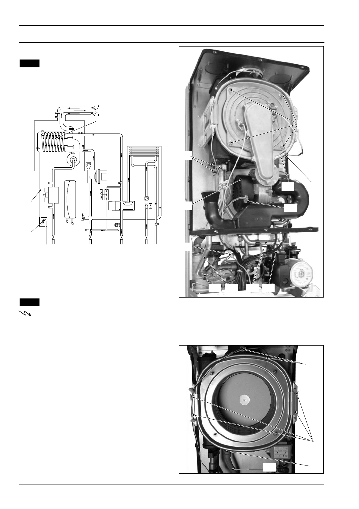
5 Condensing heat exchanger
5.1 Function
The Condensing heat exchanger A in Fig. 5.1 has the
function of transferring heat produced from combustion of the gas and from the flue exhausted gas to the
water circulating in it.
A
C
B
Fig. 5.1
By reducing the combustion products temperature, the
latent heat of the vapour is transferred to the water circuit, allowing an extra gain of useful heat.
The condensed vapour is then drained through the
condensate trap B and the draining pipe C.
H
J
IFEI
D
KLM N
G
5.2 Removal
Warning: isolate the boiler from the mains
electricity supply before removing any
covering or component.
1 D isconnect the flue system from the boiler.
2 Remove the fan group (rubber pipe, gas pipe) fol-
lowing the instructions from 1 to 6 in section 17.2.
3 D isconnect the detection electrode connector D,
the ignition electrodes connector E and the earth
wire F.
4 D isconnect the fan connector G by pressing the
plastic hook placed on the side of the connector
(Fig. 5.2).
5 Unscrew the nuts H (Fig. 5.2).
6 Remove the fan---burner group I.
7 Empty the primary circuit of the boiler.
8RemovetheclipsJ (Fig. 5.2).
9 Loosen the connection K and slightly move the
pipe L upwards, turn it towards left (Fig. 5.2) and
then move the pipe downwards freeing it from the
Condensing heat exchanger.
Fig. 5.2
10 Loosen the connection M and slightly move the
pipe N upwards, turn it towards left (Fig. 5.2) and
then move the pipe downwards freeing it from the
Condensing heat exchanger.
R
Q
P
O
10
Fig. 5.3
Page 13
Condensing heat exchanger
11 Using pliers, remove the spring O moving it
downwards and disconnect the rubber pipe P
(Fig. 5.3).
12 Unscrew the screws Q and remove the clamps
(Fig. 5.3).
13 Disconnect the two connectors R by pressing the
plastic hook placed on the side of the connector
(Fig. 5.3).
14 Remove the Condensing heat exchanger by
levering it and sliding it forwards.
15 Reassemble the Condensing heat exchanger
carrying out the removal operations in reverse
order.
Ensure to tight the nuts H --- Fig. 5.2 firmly
5.3 Cleaning
If there are deposits of dirt on the coil of the Condensing
heat exchanger, clean with a bristle paintbrush and re-
move the dust with a hoover.
Warning: After cleaning or replacement as
detailed above, if it deemed necessary to
undertake a combustion analysis, refer to
the appropriate chapter Maintenance of the
installation instructions manual.
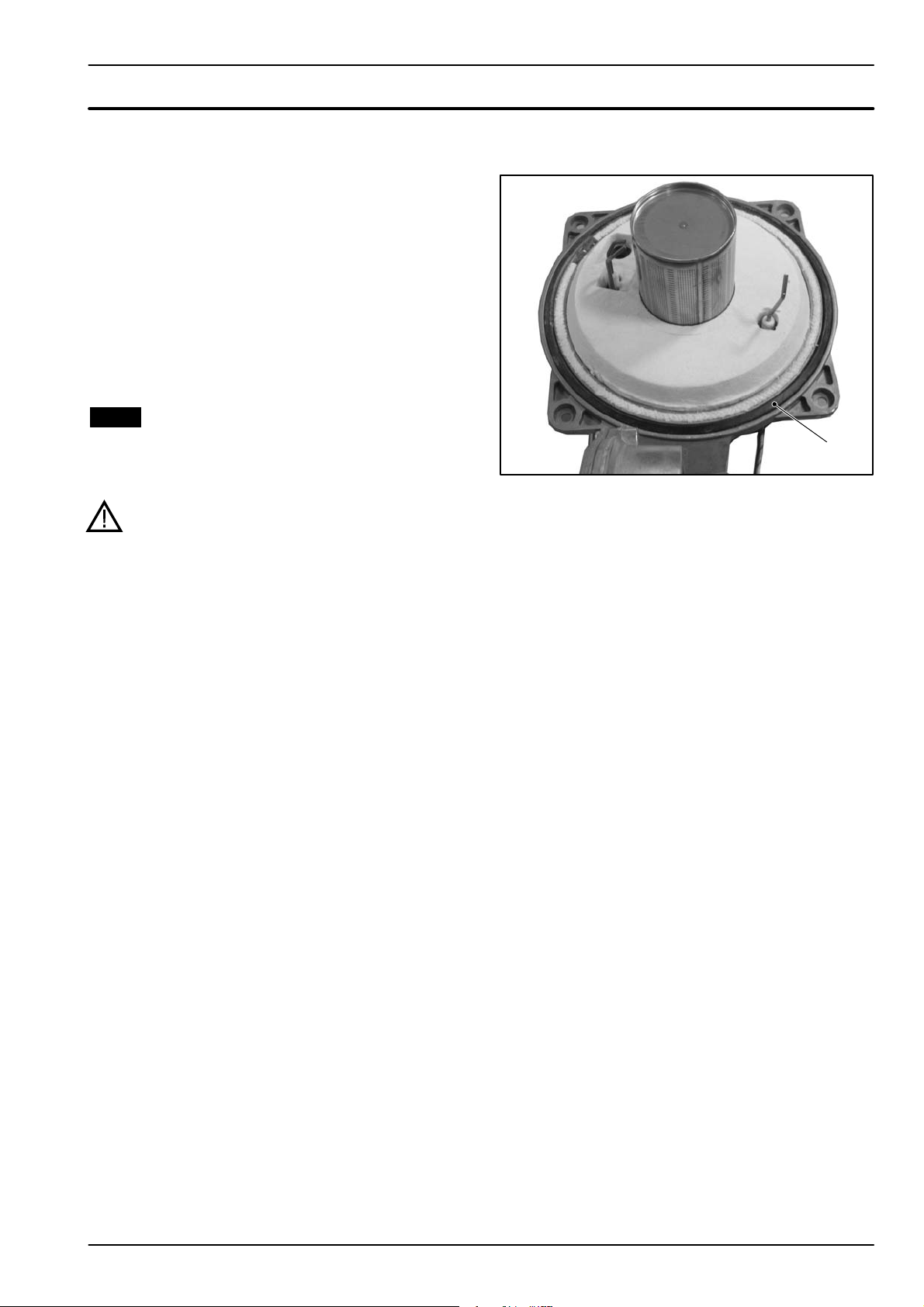
S
Fig. 5.4
The siliconic gasket S Fig. 5.4 m ust be replaced
every 2 years.
11
Page 14
6 D.h.w. heat exchanger
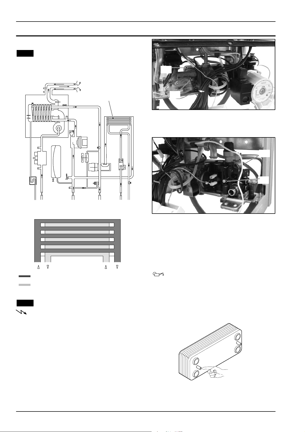
6.1 Function
The d.h.w heat exchanger A in Fig. 6.1 and Fig. 6.3 allows the instantaneous transfer of heat from the primary
hydraulic circuit to the water destined for d. h.w use.
A
A
Fig. 6.1
The schematic structure is shown in Fig. 6.2.
B
Fig. 6.3
5 Remove the pump following the instructions in
section 7.3.
A
C
Fig. 6.4
6 Completely unscrew the Allen key screws C
(Fig. 6.4) w hich hold the exchanger to the plastic
groups.
7 Move the exchanger towards the rear of the boiler
and extract it.
Reassemble the d.h.w.heat exchanger carrying out the
removal operations in the reverse order.
Primary hydraulic circuit
Domestic hot water circuit
Fig. 6.2
6.2 Removal
Warning: isolate the boiler from the mains
electricity supply before removing any
covering or component.
1 Remove the front and right hand side panels of
the case.
2 Empty the primary circuit and the d.h.w circuit of
the boiler.
3 Completely unscrew the A llen key screws B
(Fig. 6.3) which hold the exchanger to the brass
group.
4 Remove the electric actuator following the in-
structions in section 8.3.
12
Warning: to lubricate the O-- ring gaskets
exclusively use a silicone base grease
compatible to be in contact with foods and
approved by the local water Authorities.
Attention. When reassembling the exchanger be
sure to put the off centre location/securing pin indicated in Fig. 6.5 towards the left side of the boiler.
Fig. 6.5
Page 15
7 Pump
7.1 Function
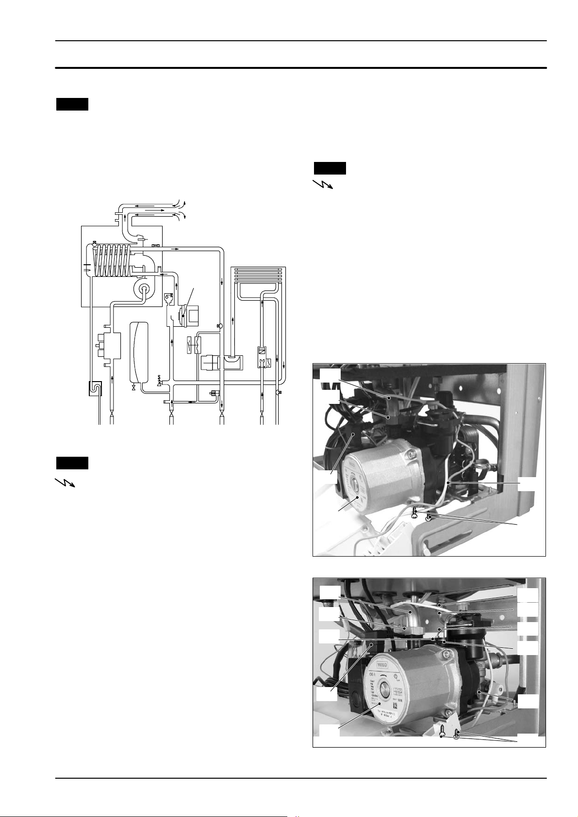
The pump A in Fig. 7.1 and Fig. 7.2 has the function of
making the water in the main circuit circulate through
the main condensing heat exchanger and therefore
through the c.h. system (during the c.h. function) or
through the secondary heat exchanger (during the
d.h.w. function).
A
n Check that the impeller is integral with the rotor.
With the boiler off remove the front and right hand side
case panels, lower the control panel and empty the pri mary circuit.
Remove the pump head by undoing the screws which
hold it to the pump body and check that the impeller is
firmly joined to the rotor.
7.3 Removal
Warning: isolate the boiler from the mains
electricity supply before removing any
covering or component.
1 Remove the front and right hand side case pan-
els.
2 Empty the primary circuit of the boiler.
3 Extract and lower the control panel.
4 Disconnect the connector B (Fig. 7.2)(Fig. 7.3).
5 Loosen the connection C,and pull up and turn to
the left the pipe D.
6 C.h. only model remove the fork E and remove
pressure gauge connection F (Fig. 7.3)
7 C.h. only model remove the fork G, loosen the
connection H and remove the pipe I (Fig. 7.3)
Fig. 7.1
7.2 Checks
Warning: isolate the boiler from the mains
electricity supply before removing any
covering or component.
n Check that the pump is not seized and that the
movement of the rotor is not subject to mechanical impediments.
With the boiler off, remove the front panel. Remove the
air release plug of the pump and turn the rotor with a
screwdriver.
n Check the electrical continuity.
With the boiler off, remove the front panel and disconnect the connector B (Fig. 7.2).
Measure the electrical resistance between the pump
supply connections.
D
C
B
A
Fig. 7.2
D
C
E
J
K
H
I
F
G
Electrical resistance of the windings (at ambient temperature) must be about 230 8.
n Check the absence of starting defects.
With the boiler off remove the front case panel.
Remove the air release plug from the pump. Start the
boiler and with a screwdriver, turn the rotor in the direction of the arrow. If there is a defect in starting, the rotor
will begin to turn normally only starting it manually.
B
A
Fig. 7.3 c.h. only model
8 Remove the locking plate J.
J
K
13
Page 16

Pump
9 Unscrew the two screws K that hold the pump on
theframeandremovethepump.
Reassemble the pump carrying out the removal operations in the reverse order. When reassembling the
pump, check the correct location of the O---ring gasket
in the inlet port of the pump that seals the connection
between the pump and the plastic group.
14
Page 17
8 Three way diverter valve
8.1 Function
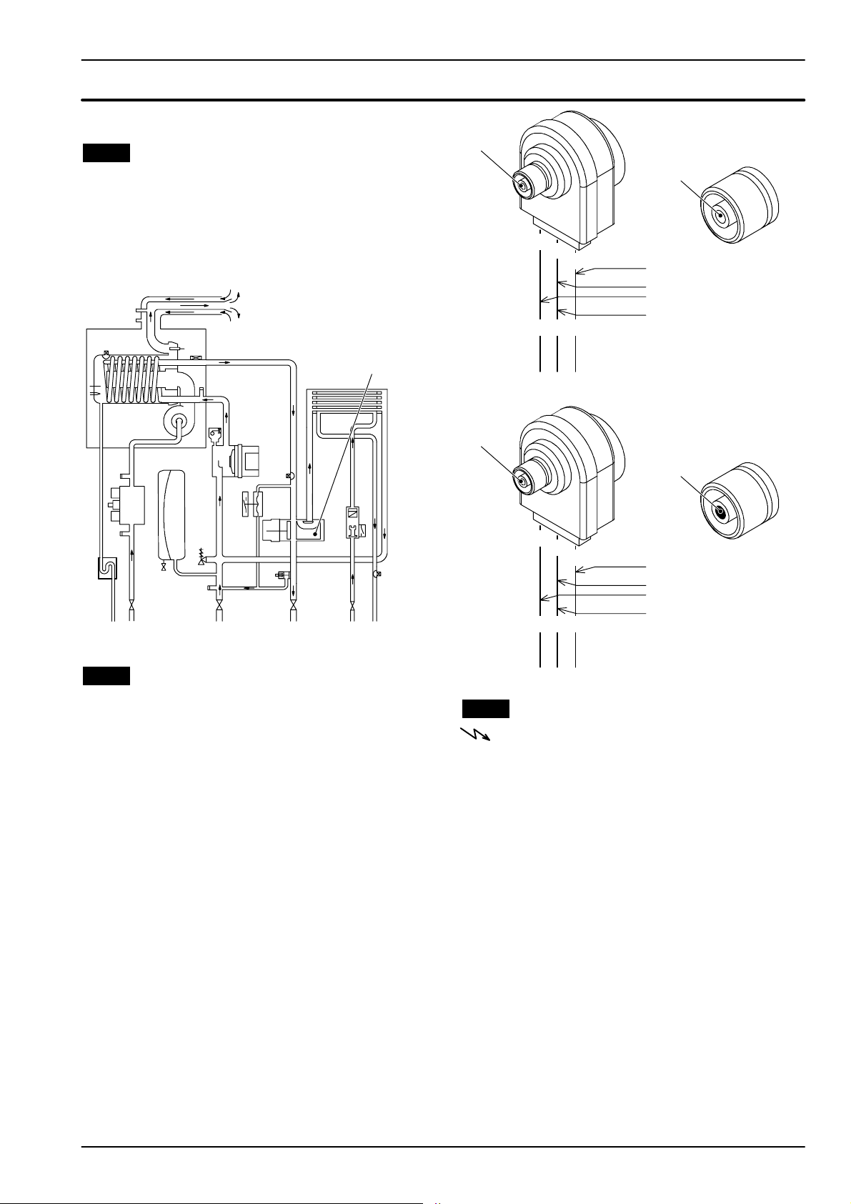
The diverter valve A (Fig. 8.1) has the function of modifying the hydraulic circuit of the boiler by means of an
electric command given by the electronic control p.c.b.
in order to send the water that exits the primary heat exchanger towards the c. h. system or towards the d.h.w.
heat exchanger.
A
B
3
2
rd = r ed
bk = black
wh = white
F i g . 8 . 2 --- D . h . w . m o d e
B
bk
wh
230 V
3
2
Spindle B
not visible
1
9,4 Kohm
Open circuit
rd
0V
Spindle B
visible
1
Open circuit
Fig. 8.1
8.2 Checks
n Check the electrical continuity
Fig. 8.2 indicates the relationship between the electric
command coming from the electronic control p.c.b.
and the positionof the actuator B (brass spindle) when
the boiler operates in d.h.w. mode.
Fig. 8.3 indicates the relationship between the electric
command coming from the electronic control p.c.b.
and the position of the actuator B (brass spindle) when
the boiler operates in c.h. mode.
In both figures the relationship between the position of
the actuator and the resistance of the motor windings
(the motor must be disconnected from the wiring) is
also given.
rd = r ed
bk = black
wh = white
F i g . 8 . 3 --- C . h . m o d e
wh
bk
0V
rd
230 V
9,4 Kohm
8.3 Removal of the electric actuator
Warning: isolate the boiler from the mains
electricity supply before removing any
covering or component.
1 Remove the front case panel.
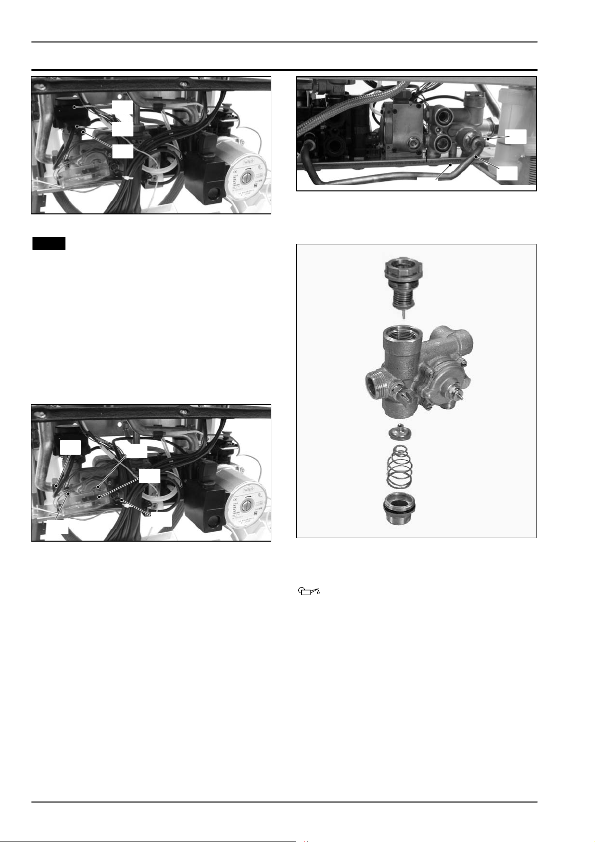
2 D isconnect the connectors C (Fig. 8.4).
3 Remove the fixing spring D and remove the
actuator E.
Reassemble the actuator carrying out the re -
moval operations in the reverse order.
When reassembling the actuator, refer to Fig. 8.2
--- Fig. 8.3 or to the wiring diagram in section 8.2
for the correct wiring connection.
15
Page 18
Three way diverter valve
E
C
D
Fig. 8.4
8.4 Removal of the diverter group and its
internal parts
1 Removethefrontandbothsidecasepanels.
2 Empty the primary circuit and the d.h.w. circuit of
the boiler.
3 Remove the electric actuator (see section 8.3).
4 Remove the fixing spring F (Fig. 8.5) and remove
the primary circuit flow switch G.
5 D isconnect both c.h. and d.h.w. temperature
probe, respectively H and I .
6 Unscrew the connector J, the c.h. flow connector
and the d.h.w. outlet connector.
L
L
M
Fig. 8.6 Rear view of the boiler
10 Refer to the exploded view in Fig. 8.7 to remove
the internal parts of the three way diverter valve.
J
H
Fig. 8.5
F
G
I
7 Remove the d.h.w. heat exchanger (see section
6.2).
8RemovetheforkK andmoveawaythepipeL
(Fig. 8.6).
9 Unscrew the screw M andremovethediverter
group.
Fig. 8.7
11 Reassemble the diverter group carrying out the
removal operations in the reverse order.
Warning: to lubricate the O-- ring gaskets
exclusively use a silicone base grease
compatible to be in contact with foods and
approved by the local water Authorities.
16
Page 19
9 Electronic control/ignition p.c.b.
9.1 Function
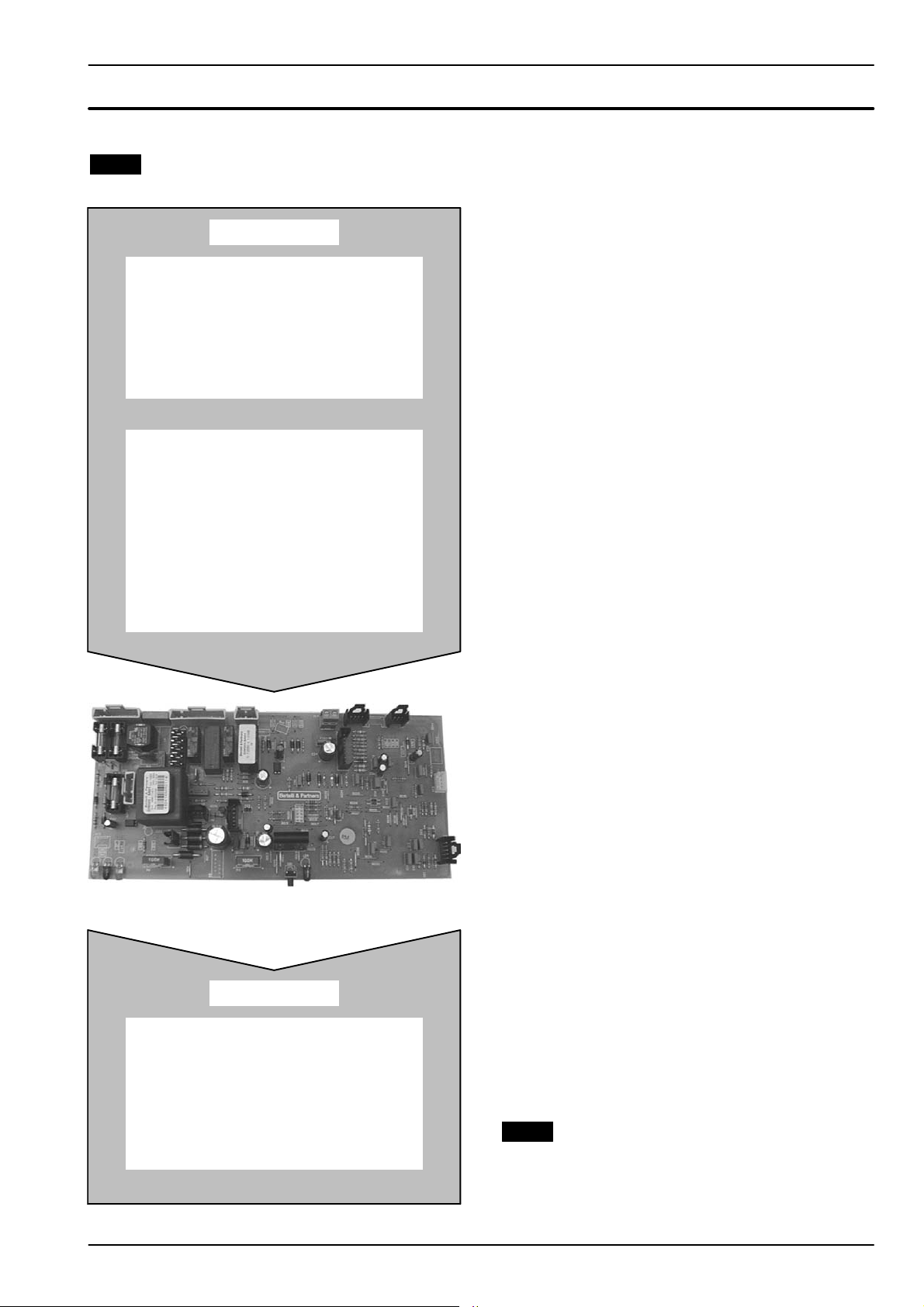
Inlet Information
On the Electronic control/ignition
p.c.b.......
Function control
C.h. temperature adjustment
D.h.w. temperature adjustment
Boiler reset button
(control panel fascia)
From other boiler devices....
C.h. temperature probe NTC
D.h.w. temperature probe NTC
D.h.w. flow switch
Primary circuit flow switch
Flue temperature probe NTC
Safety thermal fuse
Safety thermostat
Flame detection electrode
Room thermostat (if fitted)
Time switch
Outlet command
Pump
Three way diverter valve
Gas valve
Fan
Ignition electrodes
Appliance operation lights*
L o c k --- o u t s i g n a l l a m p *
*control panel fascia
Fig. 9.1
The fundamental function of the Electronic control/ignition p.c.b. is that of controlling the boiler in relation t o
the external needs (i.e. heating the dwelling or heating
the water for d. h.w. use) and operating in order to keep
the temperature of the hydraulic circuits constant.
This is obviously possible within the useful power and
maximum working temperature limits foreseen.
Generally, the Electronic control/ignition p.c.b. receives
inlet information coming from the boiler (the sensors)
or from the outside (knobs, room thermostat, etc.), processes it and consequently acts with outlet commands
on other components of the boiler (Fig. 9.1).
The Electronic control/ignition p.c.b. is also a full sequence ignition device and does a sequence of operations (ignition cycle) which lead to the ignition of the
gas at the burner
It checks the presence of the flame during the entire
period in which it is activated and supplies the fan regulating its speed.
The Electronic control/ignition p.c.b. has a safety func-
tion and any incorrect interventions or tampering can
result in conditions of dangerous functioning of the
boiler.
The Electronic control/ignition p.c.b. can lock the functioning of the boiler (lock state) and stop its functioning
up to the resetting intervention. The lock is signalled by
the lighting of the lock--- out signal lamp and the device
can be reset only by using the boiler reset button
placed on the control panel fascia.
Some components which are connected to the device
can activate the lock state. The causes of a lock state
could be:
f The intervention of the safety thermostat (over-
heat of the primary circuit).
f The intervention of the flue temperature probe
(overheat of the combustion products).
f A fault on gas supply.
f Faulty ignition (faulty ignition electrodes, their wir-
ing or connection).
f Faulty flame detection (faulty detection electrode,
its wiring or connection).
f Faulty condensate drainage.
f Faulty gas valve (faulty on ---off operators or not
electrically supplied).
f Faulty Electronic control/ignition p.c.b..
Other components like the primary circuit flow switch
can temporarily stop the ignition of the burner but allow
its ignition when the cause of the intervention has
stopped.
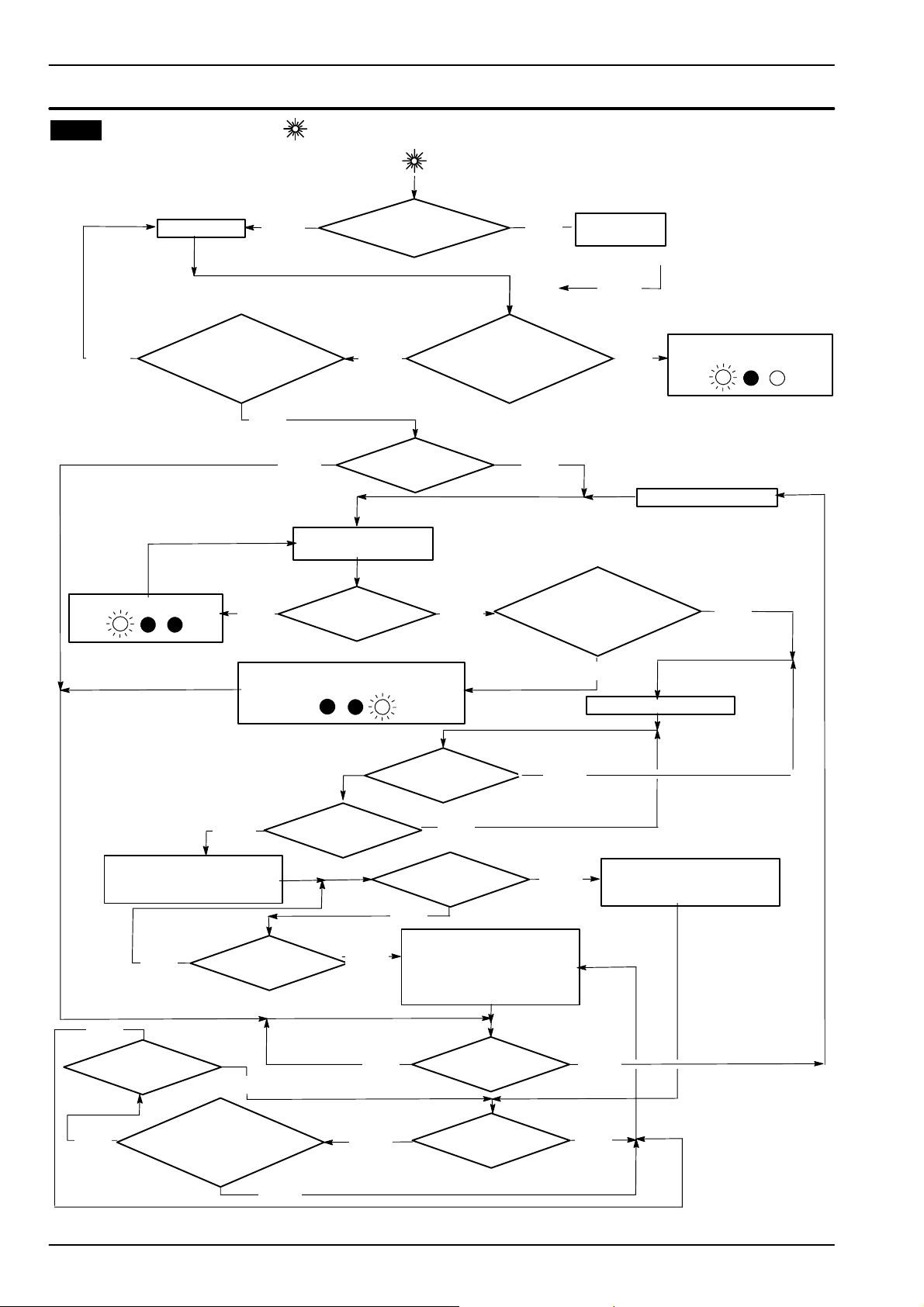
Fig. 9. 20 and Fig. 9.21 show the sequence of the operations that are carried out at the start of every ignition
cycle and during normal functioning.
9.2 Selection and adjustment devices
On the Electronic control/ignition p.c.b. several selection, adjustment and protection devices are located.
(Fig. 9.2).
Some of these devices are directly accessible by the
user (function control, temperature adjustment poten-
17
Page 20
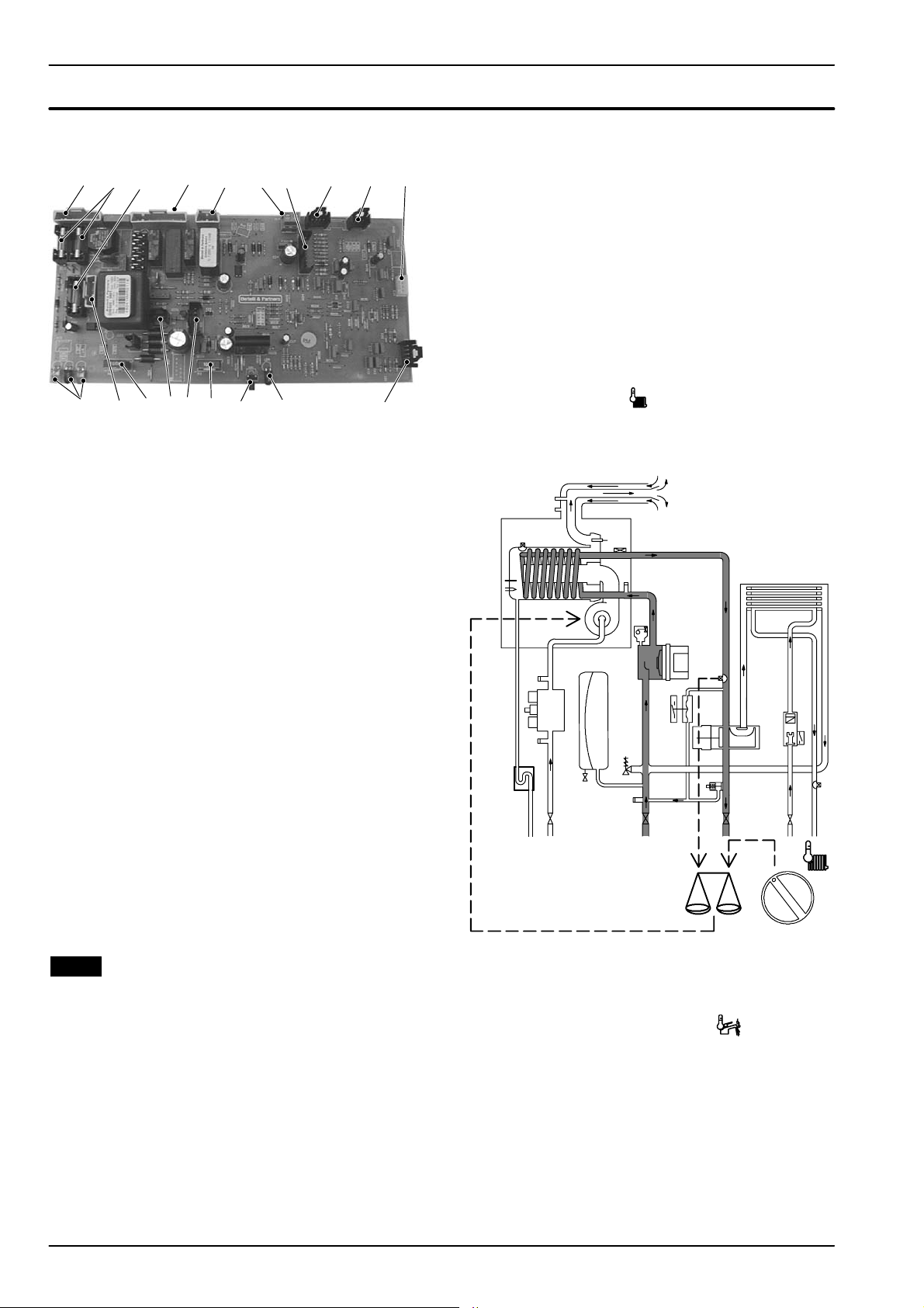
Electronic control/ignition p.c.b.
tiometers etc.) others, like the fuses, are accessible by
removing the service panel.
32 6 10
13 1112141719 151618
Fig. 9.2
91 7 84 5
1 x7 connector --- electric supply terminal block and
external controls terminal block.
2 Fuse F1, F2 3,15 A F
3 Fuse F3, 400 mA T
4 x12 connector --- pump and 3way diverter valve
5 x17 connector --- gas valve
6 x14 connector --- external temperature probe
(optional)
7 x9 connector --- safety thermostat, flue t empera-
ture probe NTC, c.h. temperature probe NTC
8 x11 connector --- d.h.w. temperature probe
9 x10 connector --- d.h.w. flow switch
10 x13 connector --- remote control (optional)
11 x2 connector --- timer
12 Lock --- out signal lamp
13 Boiler reset button
14 Function control / C.h. temperature adjustment
15 x22 connector --- fan
16 x24 connector --- transformer
17 D.h.w. temperature adjustment
18 x5 connector --- transformer
19 Appliance operation lights
9.3 Checking the temperature
The Electronic control/ignition p.c.b. makes it possible
to separately adjust the c. h. water flow temperature and
d.h.w. outlet temperature.
The temperature of the water is converted into an elec tric signal by means of temperature probes.
The user, setting the desired temperature with the control panel knobs operates the variable elements (14 and
17 in Fig. 9.2) of the electronic control p.c.b.
If the power requested is lower than 40% of the maximum power output then control is achieved by switching ON the burner at minimum power, then switching
OFF (ON/OFF function). If the power requested is
higher, then the burner is switched ON at maximum
power and will control by modulating to 40% of the
maximum power output.
During the c.h. operation (Fig. 9.3), the signal coming
from the c.h. temperature probe is compared to the signal given by the control panel through the adjustment
made by the user (knob
). The result of such a com-
parison operates the fan speed thus regulating the gas
flow rate and consequently changing the useful output
of the boiler.
Fig. 9.3
When the boiler functions in d.h.w. (Fig. 9.4), the signal
coming from the d.h.w. temperature probe is compared
with the signal given by the control panel through the
adjustment made by the user (knob
).
18
Page 21
Electronic control/ignition p.c.b.
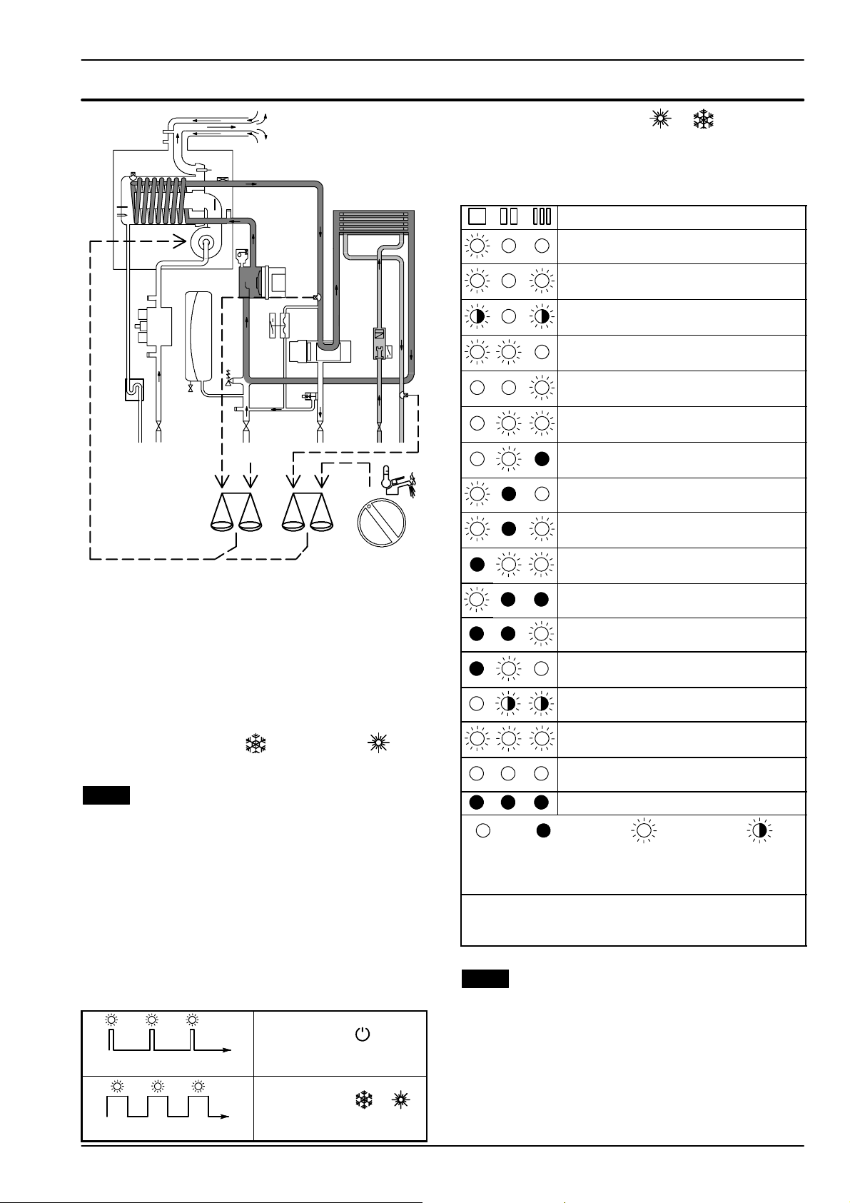
With the boiler switched ON ( or )allthelamps
(19 in Fig. 9.2) are activated.
The following table gives the relationship between each
of the possible lamp combinations and their meaning.
Normally operating boiler
(see the p revious table for details)
C.h. operation
D.h.w. operation
Frost protect operation
D.h.w. operation
Excessive temperature on primary circuit
Faulty c.h. temperature probe NTC
90 ˚C
Fig. 9.4
Normally, the result of the comparison between these
two signals directly operates the fan speed adjusting
the useful output generated in order to stabilize the
temperature of the exiting water.
If during the d.h.w. mode operation, the temperature of
the primary circuit goes over 90qC, the useful output is
automatically reduced so that the primary circuit can-
not reach excessive temperatures.
The control sequences in
function and in func-
tion are illustrated in detail in sections 9.11 and 9.12.
9.4 Operation lights
The Electronic control/ignition p.c.b. is provided with
three lamps (L.E.D. indicators) 19 in Fig. 9.2 that give
optical information during the operation of the boiler.
The green lamp on the left gives information whether
the boiler is in stand ---by mode or during the normal
operation of the boiler.
The following table gives the relationship betw een the
lamps indication and their meaning.
Faulty d.h.w temperature probe NTC
Faulty primary circuit
(no water or absence of flow)
Lack of burner ignition
Safety thermostat lock out
Faulty fan control system
Flue temperature probe NTC lock out
Open flue temperature probe NTC
Faulty external temperature probe NTC
Flame detection error
Lack of power supply or faulty electronic
control p.c.b.
Faulty Electronic control/ignition p.c.b.. *
Lamp
OFF
* These conditions are normal only for a short time when the
power supply is applied to the boiler.
If permanent they indicate a faulty p.c.b.
Lamp
ON
Flashing lamp, alone
or simultaneously
with an other lamp.
Flashing lamp,
alternate with
another lamp.
A short pulse every 4 seconds
1secondON1secondOFF
Boiler in stand --- by condition.
(function control in
position).
Anti--- freeze system active.
Boiler ON condition
(function control in or
position)
9.5 Setting the boiler control function modes
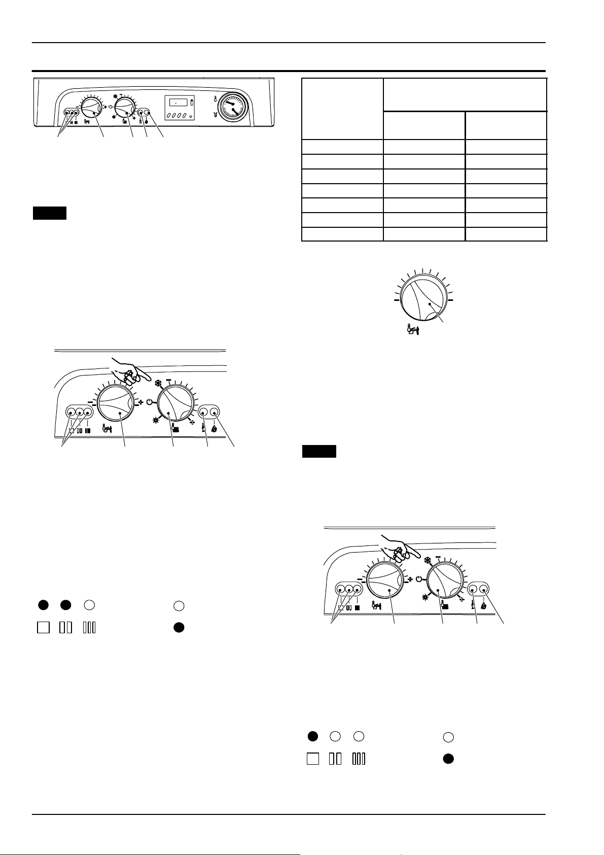
It is possible to select the various boiler control function
modes by using the function selector knob A and the
D.h.w. temperature control knob B (Fig. 9.5).
On model M110B.24SR/... the knob B is used just for
boiler setting and doesn’t affect the boiler functions
during the normal operation.
During the function modes setting, the boiler does not
operate.
19
Page 22
Electronic control/ignition p.c.b.
A
B
Fig. 9.5
CED
9.6 Adjustment of maximum useful output in
c.h. mode
The following procedure allows the output of the boiler
for c.h. to be limited to meet the system requirement.
Adjusting the maximum useful output in c.h. mode
does not prevent the boiler firing at maximum rate for
d.h.w. production.
1 Turn the boiler ON positioning the function selec-
tor knob A as indicated in Fig. 9.6.
Knob position Maximum useful output in c.h. mode
1 5,8 (19 789) 8,2 (27 977)
2 9,0 (30 707) 12,4 (42 307)
3 12,2 (41 625) 16,5 (56 296)
4 15,5 (52 884) 20,7 (70 626)
5 18,7 (63 802) 24,8 (84 614)
6 21,9 (74 720) 29,0 (98 944)
7 25,1 (85 638) 33,1 (112 933)
Tab . 9 . 1
non condensing
kW (BTU/h)
M110B.24SM/...
M110B.24SR/...
4
3
2
1
M110B.32SM/...
5
6
7
B
Fig. 9.8
5 To memorize the setting keep pressed the reset
button C for about 5 seconds until the lights E
briefly blinks simultaneously.
6 To reset the boiler to the normal operation turn it
OFF and ON by the function selector knob A. In
any case, the boiler automatically resets to its normal operation after 10 minutes.
E
Fig. 9.6
AB
C
D
2 Keep pressed the reset button C for about 10 sec-
onds until the lock--- out signal lamp D blinks.
3 The lamps E should give the indication as in
Fig. 9. 7 (maximum c.h. useful output adjust-
ment). If not, press the reset button repeatedly to
obtain it.
Where:
Fig. 9.7
Lamp OFF
Lamp ON
At this step it is possible to visualize the current setting
by keeping the reset button C pressed for more than 5
seconds. The lamps will flash a number of times corresponding to the setting (Tab. 9.1 and Fig. 9.8).
4 To change the setting turn the knob B on a posi-
tion corresponding to the desired maximum use-
ful output (Tab. 9.1 and Fig. 9.8).
By turning the knob B, the lock ---out signal lamp
D blinks quickly (2 per seconds) indicating that
the setting has changed and must be memo-
rised.
20
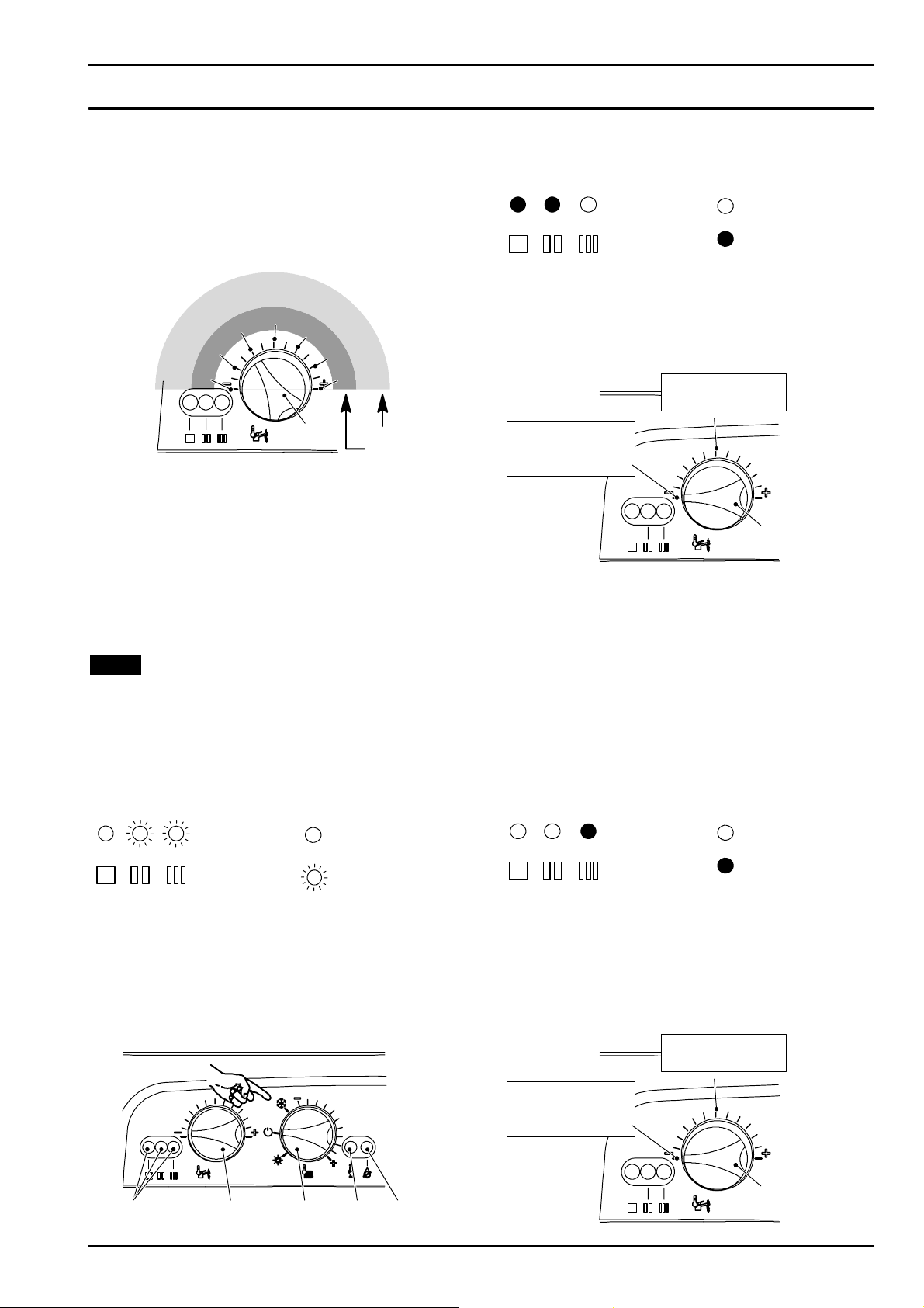
9.7 Reignition frequency setting
It is possible to select the minimum time that must pass
between two ignitions of the burner in c.h. function
mode.
1 Turn the boiler ON positioning the function selec-
tor knob A as indicated in Fig. 9.9.
E
Fig. 9.9
2 Keep pressed the reset button C for about 10 sec-
onds until the lock--- out signal lamp D blinks.
3 The lamps E should give the indication as in
Fig. 9. 10 (reignition frequency). If not, press the
reset button repeatedly to obtain it.
Where:
Fig. 9.10
At this step it is possible to visualize the current setting
by keeping the reset button C pressed for more than 5
AB
C
Lamp OFF
Lamp ON
D
Page 23
Electronic control/ignition p.c.b.
seconds. The lamps will flash a number of times corre-
sponding to the setting (Fig. 9.11).
4 To change the setting turn the knob B on a posi-
tion corresponding to the desired delay.
By turning the knob B, the lock ---out signal lamp
D blinks quickly (2 per seconds) indicating that
the setting has changed and must be memorised.
4
51/2
4
5
7
6
7
81/2
B
Delay (minutes)
Setting No.
Fig. 9.11
11/2
0
3
3
2
1
5 To memorize the setting keep pressed the reset
button C for about 5 seconds until the lights E
briefly blinks simultaneously.
6 To reset the boiler to the normal operation turn it
OFF and ON by the function selector knob A. In
any case, the boiler automatically resets to its normal operation after 10 minutes.
Factory setting = 3 minutes
9.8 Combi / C.H. only mode setting
Two different options are available on the Electronic
control/ignition p.c.b. and proper setting must be done
after a replacement of the p.c.b.
1 Remove the front panel of the case.
2 Turn ON the power supply. Lamps E give the in-
dication as in Fig. 9.12.
6 Press the reset button C repeatedly (2 times) until
the lamps E give the indication as in Fig. 9.14
(boiler mode).
Where:
Fig. 9.14
Lamp OFF
Lamp ON
At this step it is possible to visualize the current setting
by keeping the reset button C pressed for more than 5
seconds. The lamps E will flash a number of times
corresponding to the setting (Fig. 9.15).
M110B.24SR/...
4flashes
M110B.24SM/...
M110B.32SM/...
1flash
B
Fig. 9.15
7 To change the setting turn the knob B on a posi-
tion corresponding to the boiler models
(Fig. 9.15). By turning the knob B, the lock--- out
signal lamp D blinks quickly (2 per seconds) indicating that the setting has changed and must be
memorised.
8 To memorize the setting keep pressed the reset
button C for about 5 seconds until the lights E
briefly blinks simultaneously.
9 Press the reset button C once until the lamps E
give the indication as in Fig. 9.16 (boiler mode).
Where:
Fig. 9.12
Lamp OFF
Lamp Flashing
3 Position the function selector A as in NO TAG and
disconnect the C.h. temperature probe.
4 Keep pressed the reset button C for about 10 sec-
onds (Fig. 9.13) until the lock--- out signal lamp D
blinks.
5 Connect the c.h.temperature probe.
E
Fig. 9.13
AB
C
D
Where:
Fig. 9.16
Lamp OFF
Lamp ON
It’s now possible to check the current setting by pressing reset button C for more than 5 seconds. The three
lamps E will flash a number of times corresponding to
the setting as in Fig. 9.17 (once for the combination and
four times for system boilers). At this point only the right
green light flashes.
M110B.24SR/...
4flashes
M110B.24SM/...
M110B.32SM/...
1flash
B
Fig. 9.17
21
Page 24
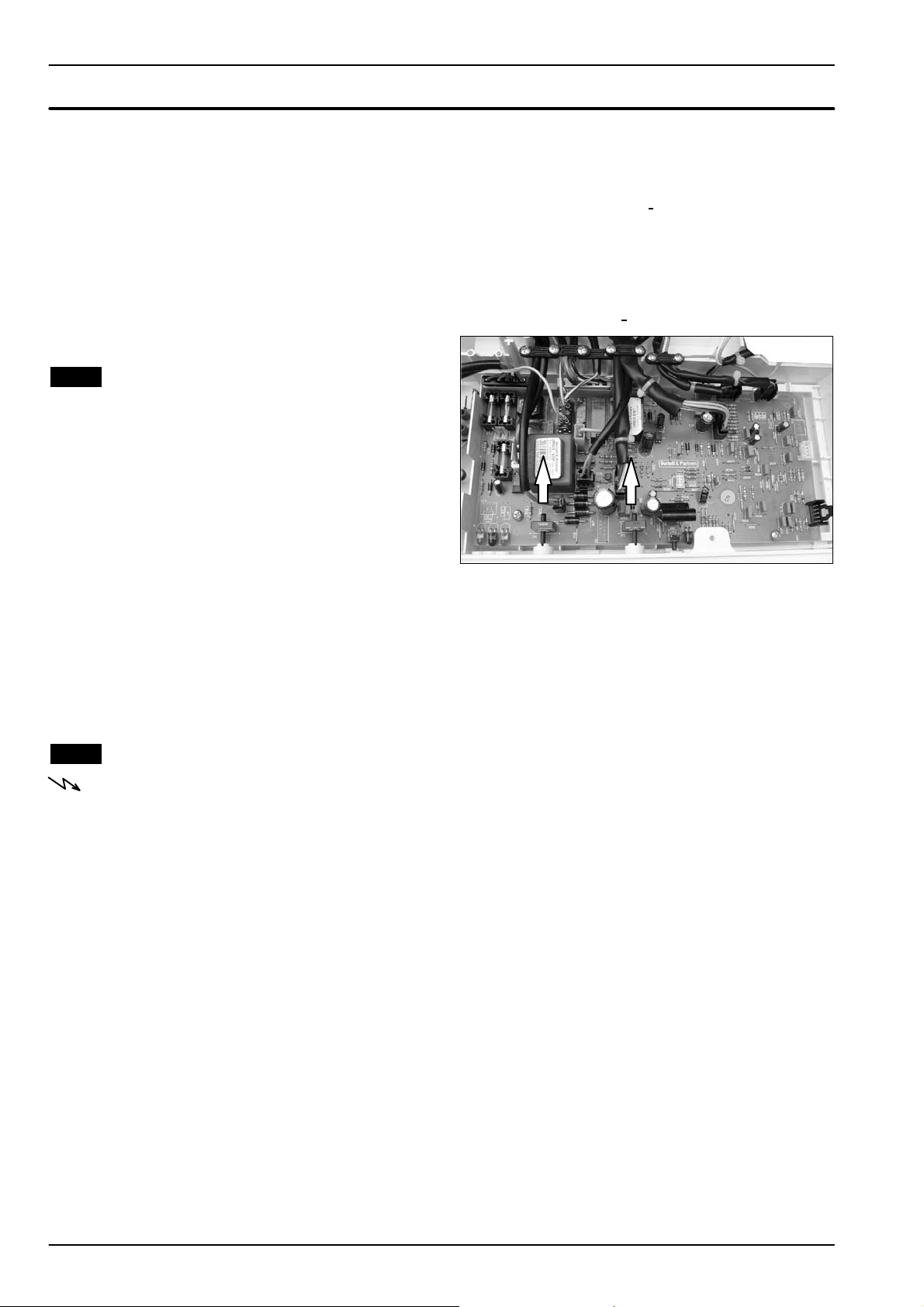
Electronic control/ignition p.c.b.
10 Turn the water control to minimum. Lock--- out
lamp blinks (2 per second) indicating the setting
has changed
11 To change the setting turn the k nob B on a posi-
tion corresponding to the boiler model
(Fig. 9.17).
12 To memorize the setting keep pressed the reset
button C for about 5 seconds until the lights E
briefly blinks simultaneously. At this point only the
right green light flashes.
13 To reset the boiler to the normal operation turn it
OFF and ON by the function selector knob A.
9.9 Checks
n Check that the fuses are complete
If the Electronic control/ignition p.c.b. does not supply
any device (pump, fan, etc.) check that the fuses 2 and
3(Fig. 9.2) are complete.
If a fuse has blown replace it with one that has the same
characteristics after having identified the reason for failure.
n Lock sequence
Start the boiler until the burner is ignited.
With the burner firing, interrupt the gas supply. The
Electronic control/ignition p.c.b. must carry out four
complete ignition cycles and then, after about 4 minutes, goes to lock --- out state.
By turning the boiler on and off by means of the function
switch the device must not unlock and the burner must
not turn on.
9.10 Removal of the electronic control p.c.b
Warning: isolate the boiler from the mains
electricity supply before removing any
covering or component.
When replacing the Electronic control/ignition
p.c.b. it is advisable to go throughthe setting modes
of the boiler here described in sections 9.5 to 9.7.
The spare electronic control/ignition p.c.b. is set for
natural gas.
If the boiler is fed with different gas type, go through
the Gas conversion operations described in the In-
stallation manual.
If an external temperature probe (optional) is fitted,
the coefficient K has also to be set as described in
the Commissioning chapter of the installation manual.
1 Gain access to the parts located inside the con-
trol panel as explained in the section 2.3 of this
manual.
2 Remove all the wiring connected to the Electronic
control/ignition p.c.b.
.
To disconnect the connectors delicately flex t he
hook present on one side of each socket.
3 Remove the spindles of the c.h. and d.h.w. tem -
perature adjustment knobs by delicately pulling
them with pliers in the direction shown by the
arrow in Fig. 9.18
Fig. 9.18
.
4 Unscrew the four screw s that hold the Electronic
control/ignition p.c.b. on to the control panel.
5 Remove it by lifting its rear edge and freeing it
from any of the wiring.
6 Re---assemble the Electronic control/ignition
p.c.b. following the removal procedures in the reverse order.
Important
When re ---assembling the Electronic control/ignition
p.c.b.:
7 It is not necessary to utilise static protections but
it is advisable to ensure that the pcb is handled
with care and h eld at the edges and with clean dry
hands.
8 Fit the p.c.b. into the control panel by first insert-
ing the front lower edge under the control knob
shafts. Lower the rear edge and ensure that no
wiring is trapped beneath.
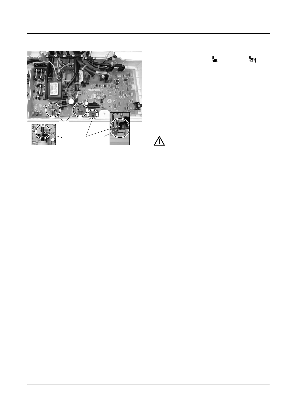
9 Insert the spindles in the control panel knobs until
the notch A (Fig. 9.19) reaches the potentiometer
edge. It is not necessary to force them in the
knob.
10 While tightening the screws that fix the Electronic
control/ignition p.c.b. on the control panel, keep
the p.c.b. towards the control panel fascia mak-
22
Page 25
Electronic control/ignition p.c.b.
ing sure of the contact between the boiler reset
button B and the tab C (Fig. 9.19).
A
Fig. 9.19
A
B
C
Attention
After installing the Electronic control/ignition p.c.b. :
11 Make sure the c.h. (
) and d.h.w. ( )tem-
perature adjustment knobs can move freely for
the complete range.
If not, remove the spindle again as described at
step 3, turn the knob half a turn and re --- insert the
spindle.
12 Make sure that the settings comply with the in-
dications given in section 9.5.
13 Operate the boiler and close the gas inlet cock so
that the boiler goes into the safety lock ---out state.
Verify the correct operation of the boiler reset button by pressing and releasing it.
Warning: After cleaning or replacement as
detailed above, if it deemed necessary to
undertake a combustion analysis, refer to
the appropriate chapter Maintenance of the
installation instructions manual.
23
Page 26
Electronic control/ignition p.c.b.
9.11 Thermal control in the ” ”mode
Switch in the function mode
YES
Operation lights
temperature higher than that
circulator on
Is primary circuit
selected?
NO
NO
YES
YES
checks fan rpm
water from the domestic hot
starts fan
Is fan rpm
exact?
Tak i n g
water circuit?
YES
lock memorised?
Main circuit pressure
YES
NO
switch consense?
NO
temperature higher than 110˚C?
circulator off
fan still
YES
NO
Is flue
stop circulator (3min)
Operation lights
cancels lock
NO
starts ignition discharges
Opens gas valve
beginning of ignition period
NO
NO
Is fan rpm
exact?
turns on lock --- out light
Opeartion lights
flame presence?
YES NO
End of ignition
period?
YES
End of wait
period?
YES
flame presence?
NO
closes gas valve
interrupts ignition discharges
memorizes lock
turns on lock --- out light
NO
r e s e t p u s h --- b u t t o n
stops fan
pressed?
YES
beginning of wait period
YES
YES
interrupts ignition discharges
YES
gas valve open
fan runs
Fig. 9.20
24
safety thermostat or flue
temperature probe lock out?
YES
YESNO
flame presence?
NO
Page 27
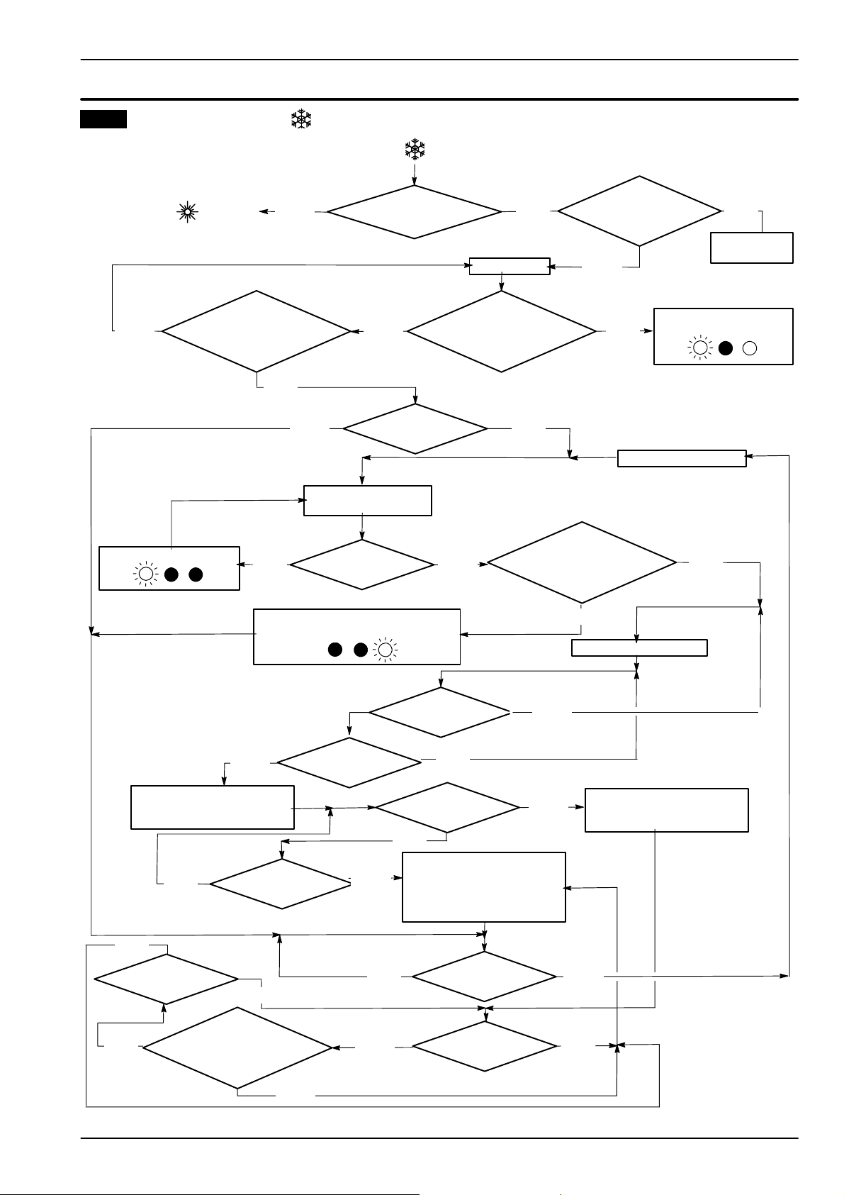
9.12 Thermal control in the ” ”mode
Switch in the function mode
Electronic control/ignition p.c.b.
See functioning with the function
control in the mode
(sec. 9.11)
YES
Opeartion lights
Is primary circuit
temperature higher than that
selected?
NO
NO
YES
YES
checks fan rpm
water from the domestic hot
starts fan
Is fan rpm
exact?
Tak i n g
water circuit?
YES
lock memorised?
Main circuit pressure
YES
NO
circulator on
switch consense?
NO
temperature higher than 110˚C?
Request for heat from
room thermostat?
YES
NO
Is flue
NO
circulator off
fan still
stop circulator (3min)
Operation lights
cancels lock
NO
starts ignition discharges
Opens gas valve
beginning of ignition period
NO
NO
Is fan rpm
exact?
turns on lock --- out light
Opeartion lights
flame presence?
YES NO
End of ignition
period?
YES
End of wait
period?
YES
flame presence?
NO
closes gas valve
interrupts ignition discharges
memorizes lock
turns on lock --- out light
NO
r e s e t p u s h --- b u t t o n
stops fan
pressed?
YES
beginning of wait period
YES
YES
interrupts ignition discharges
YES
gas valve open
fan runs
Fig. 9.21
safety thermostat or flue
temperature probe lock out?
YES
YESNO
flame presence?
NO
25
Page 28
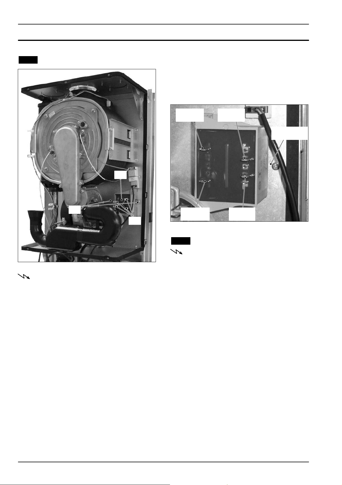
10 Transformer
10.1 Removal
2 D isconnect the four connectors A.
3 Unscrew the screws B andremovethe
Transformer C by sliding it forward.
4 Reassemble the Transformer carrying out the re-
moval operations in the reverse order.
After reassembling ensure the wires are correctly
connected (see Fig. 10.2)
C
B
A
Fig. 10.1
Warning: isolate the boiler from the mains
electricity supply before removing any
covering or component.
1 Removeallthecasepanelsandthesealed
chamber lid (see section 2).
smaller
connector
smaller
connector
Fig. 10.2
larger
connector
clamp for fitting
the transformer
larger
connector
10.2 Check the transformer
Warning: isolate the boiler from the mains
electricity supply before removing any
covering or component.
1 Remove the Transformer (see section 10.1)
2 Measure the electrical resistance of the primary
and secondary windings.
The primary should have a resistance approx. 35
ohm and the secondary approx. 1,4 ohm.
26
Page 29
11 Gas valve
11.3 Adjustment
11.1 Function
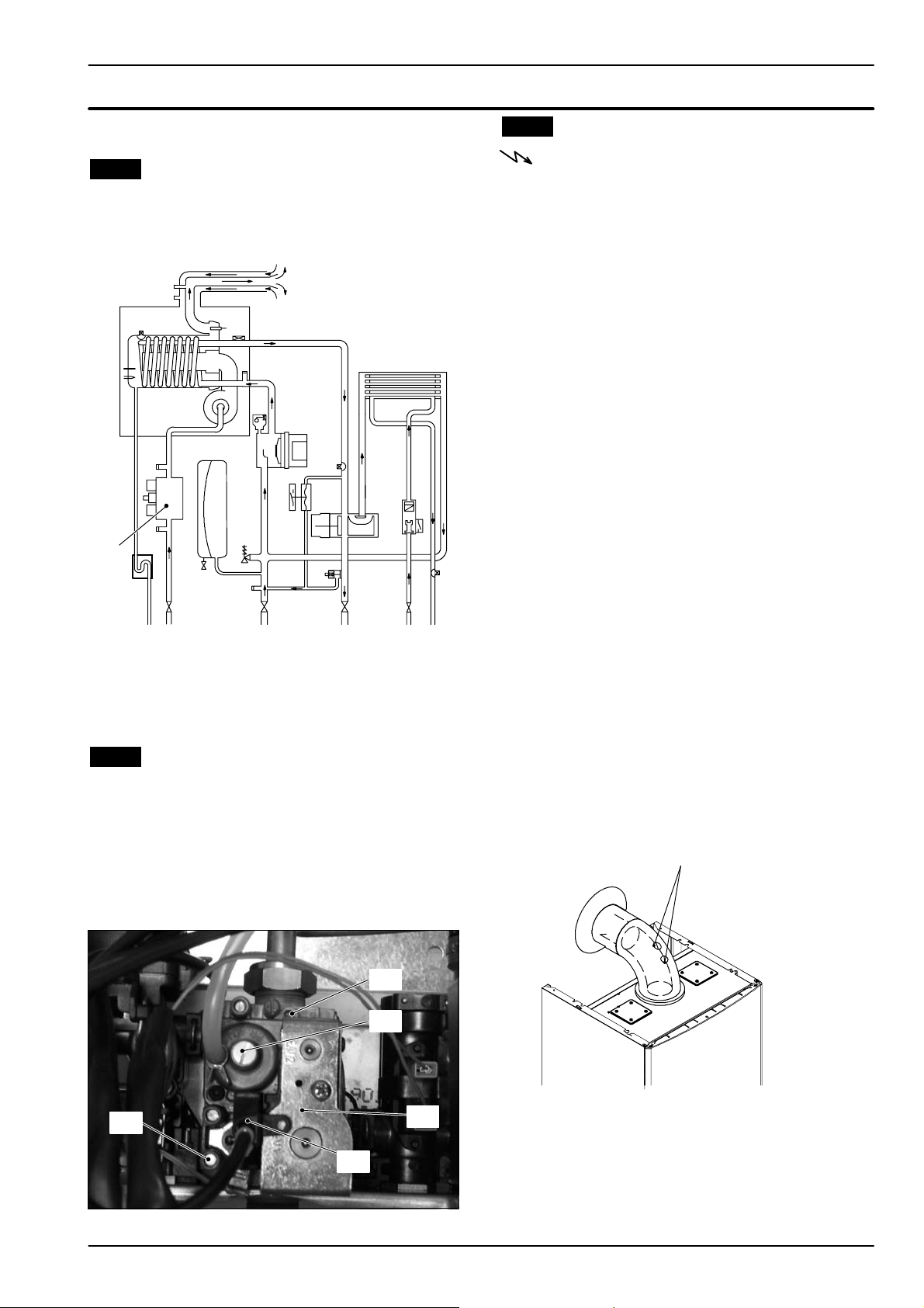
The Gas valve A in Fig. 11.1 controls the gas inflow to
the boiler burner.
A
Fig. 11.1
By means of an electric command given to the on ---off
operators the passage of the gas through the Gas valve
can be opened or closed.
Warning: isolate the boiler from the mains
electricity supply before removing any
covering or component.
Check the supply pressure before making any adjustment to the gas valve.
1 Close the gas inlet valve.
2 Remove the front panel of the case and lower the
control panel (see sections 2.2 and 2.3).
3 Loosen the internal screw on the Inlet Pressure
Test Point 5 (Fig. 11.2) of the Gas valve and connect a pressure gauge using a suitable hose.
4 Open the gas inlet valve.
5 Turn on the electricity supply to the boiler, switch-
ing on the fused spur isolation switch.
The appliance operation light on the left will flash
every 4 seconds.
6 Set the function knobs as illustrated in Fig. 11.4.
7 Open at least one hot water tap fully.
8 Read the inlet pressure value and ensure that it is
within the limits given in the table Gas supply
pressures, of the user/installation manual
If it does not comply with the required pressure
check the gas supply line and governor for faults
and/or correct adjustment.
9 Switch off the boilerclose the gas inlet valve and
close the water tap.
10 Disconnect the pressure gauge and close the
Inlet Pressure Test Point 5 (Fig. 11.2).
11.2 Description of the parts (Fig. 11.2)
1 Maximum gas pressure adjustment
2 Minimum gas pressure adjustment
3 On---off operators
4 On --- off operators electric connector
5 Gas valve inlet pressure test point
1
2
5
4
Fig. 11.2
Gas valve adjustment
11 Fit the probe of the flue analyser in the flue ex-
haust sampling point located on the exhaust
pipes of the boiler (Fig. 11.3).
air--- flue exhaust
sampling points
3
Fig. 11.3
12 Turn on the boiler, switching on the fused spur
isolation switch.
13 Open the gas inlet valve.
14 Set the function knob B as indicated in Fig. 11.4.
The appliance operation light on the left will flash
every 4 seconds.
27
Page 30
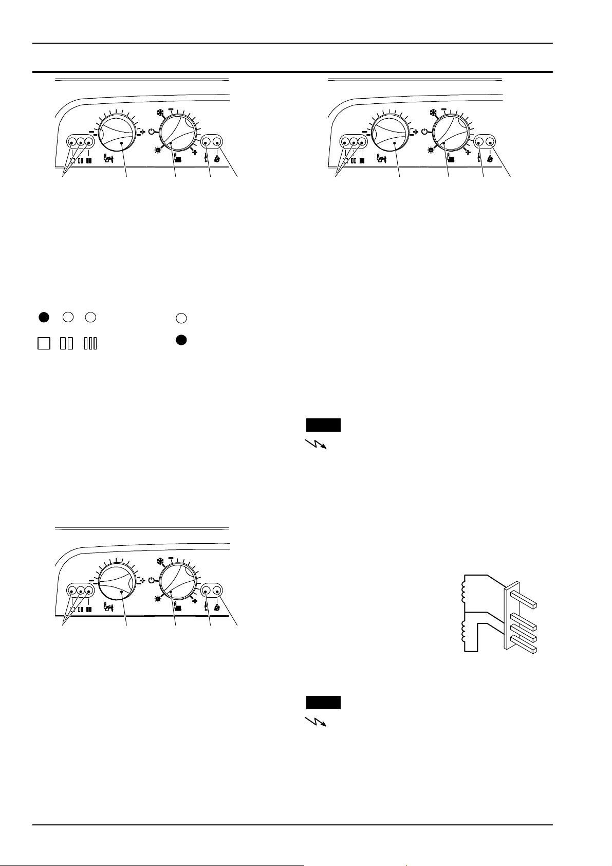
Gas valve
E
Fig. 11.4
BF
C
D
15 Keep pressed the reset button C for about 10
seconds (Fig. 11.4) until the lock--- out signal
lamp D blinks.
16 The lamps E should give the indication as in
Fig. 11.5.
Where:
Fig. 11.5
Lamp OFF
Lamp ON
17 Release and keep the reset button C pressed for
more than 5 seconds until the lock --- out signal
lamp D is switched off.
The boiler will now go through an ignition sequence and the burner w ill light.
18 Open at least one hot water tap fully.
Adjusting minimum gas valve setting
19 Set the knob F to the minimum position as illus-
trated in Fig. 11.6.
E
Fig. 11.7
BF
C
D
23 Allow the analyser to give a stable reading.
24 Read the CO
%value.
2
It should be between 9,0 and 9,8 % (natural gas
G20) or between 10,0 and 11,0 % (LPG G31).
To ad j u s t t h e CO
Fig. 11.2) (by rotating it clockwise the CO
% value rotate screw (1 ---
2
2
%de-
creases).
25 Switch off the boiler and turn off the hot wat er
tap(s).
26 Close the air---flue sampling points.
27 After adjustment fit the protective brass plug (2,
Fig. 11.2).
Important: after the gas pressure checks and any
adjustment operations, all of the test points must be
sealed.
11.4 Checks
Warning: isolate the boiler from the mains
electricity supply before removing any
covering or component.
n Check the on--- off operators coils
1 Remove the front panel of the case.
2 Disconnect the electrical connector 4 (Fig. 11.2).
3 Measure the electrical resistance between the
connector pins of the on--- off operators as illustrated in Fig. 11.8.
E
Fig. 11.6
BF
C
D
20 Allow the analyser to give a stable reading.
21 Read the CO
%value.
2
It should be between 9,0 and 9,8 % (natural gas
G20) or between 10,0 and 11,0 % (LPG G31).
To a d j u st t h e C O
% value remove the brass plug
2
by unscrewing it and rotate the Allen key screw ø
4 mm (2 --- Fig. 11.2) (by rotating it clockwise the
%increases).
CO
2
Checking the maximum gas valve setting
22 Set the knob F to the maximum position as illus-
trated in Fig. 11.7.
28
ON---OFF Operator
approx. 6 400 8*
ON---OFF Operator
approx. 920 8*
* at ambient temperature.
Fig. 11.8
11.5 Removal of the gas valve
Warning: isolate the boiler from the mains
electricity supply before removing any
covering or component.
1 Remove the front panel of the case as explained
in the section 2.3 of this manual and the sealed
chamber lid.
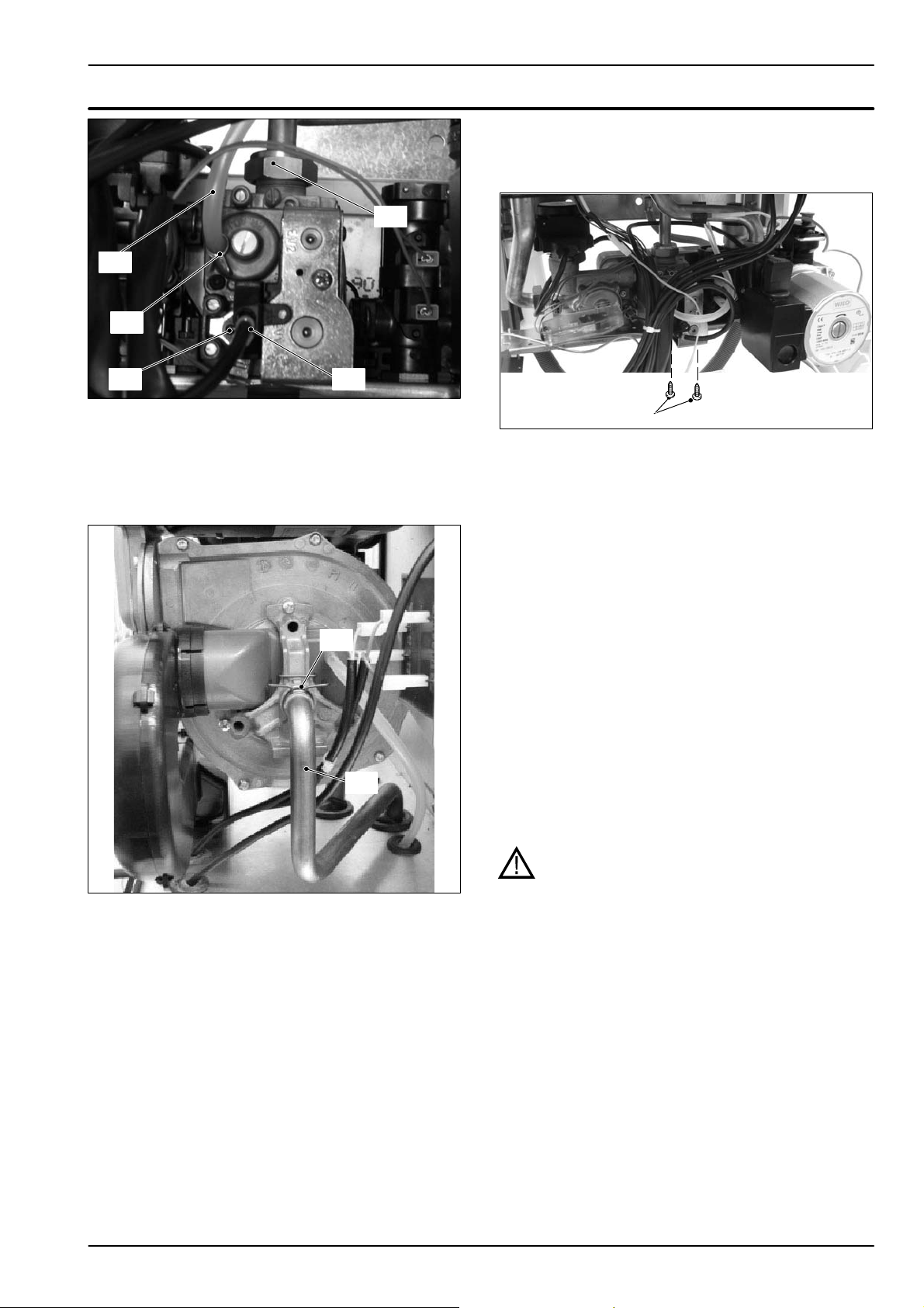
2RemovethescrewG and disconnect the con-
nector H (Fig. 11.9).
Page 31
Gas valve
5 Unscrew the connector K (Fig. 11.9), remove the
fixing fork L and remove the pipe M (Fig. 11.10).
K
J
I
HG
Fig. 11.9
3 Turn off the gas supply and disconnect the gas
isolation cock connector from the inlet port of the
gas valve.
4 Using pliers, remove the spring I and the rubber
pipe J (Fig. 11.9).
L
M
Fig. 11.10
N
Fig. 11.11
6 Unscrew the s crews N and remove the valve
(Fig. 11.11).
7 Reassemble the valve carrying out the removal
operations in reverse order.
Before to fit a new valve it is advisable to pre -- set it
as hereafter explained.
8 Remove the brass plug and turn the plastic screw
inside it fully clockwise until it stops. Do not overtight.
9 Turn it counter---clockwise 2 and 3/4 turns.
10 Adjustthegasvalveusingtheflueanalyserasde-
scribed in section 11.3.
After any service operation on the components of
the gas circuit check all the connections for gas
leaks.
Warning: After cleaning or replacement as
detailed above, it is deemed necessary to
undertake a combustion analysis as detailed
in chapter 11.3 section 11.
29
Page 32
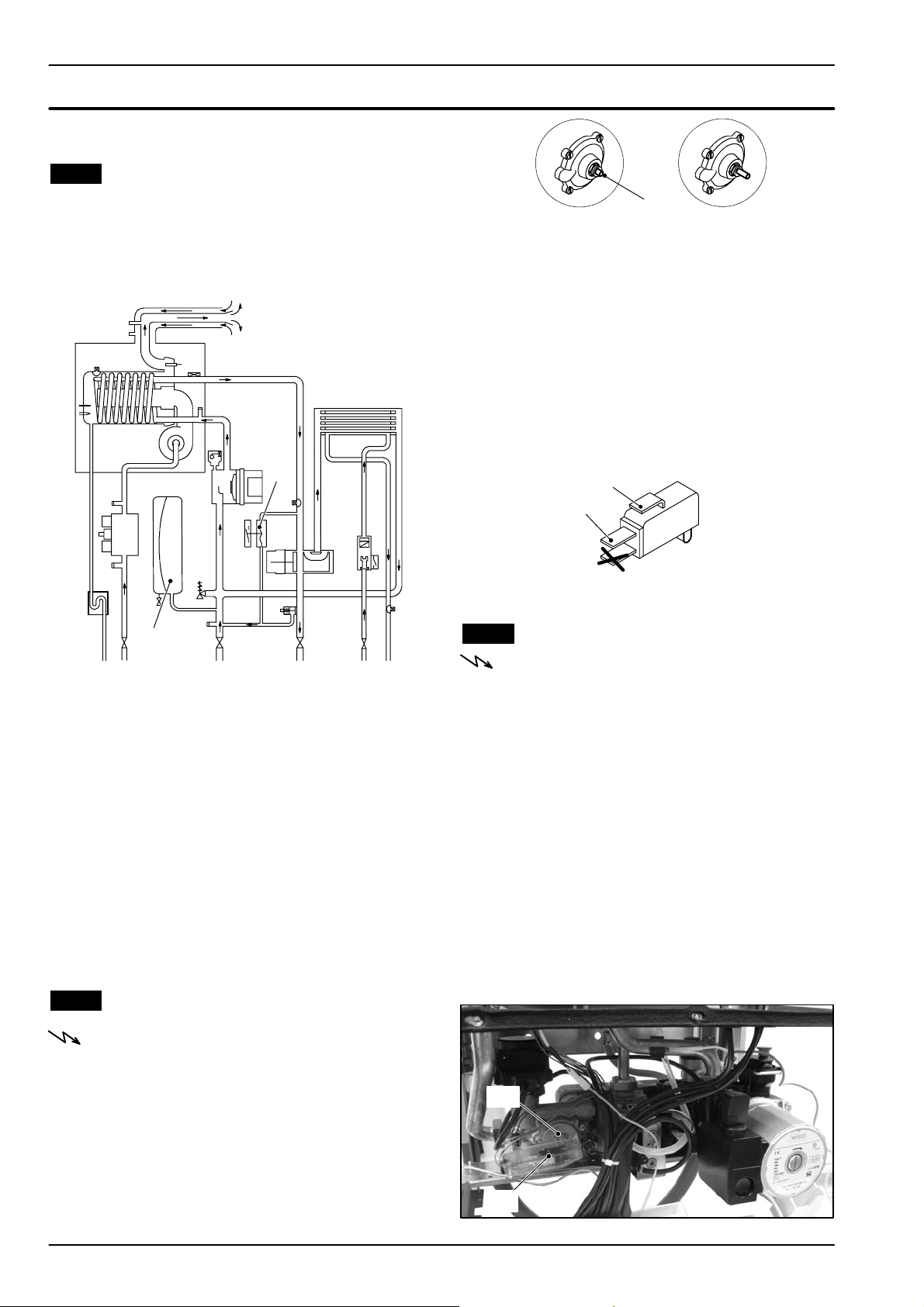
12 Primary circuit flow switch
12.1 Function
The Primary circuit flow switch (A in Fig. 12.1) function
is to detect water flow rate through the primary hydraulic circuit of the boiler.
A
I
Boiler OFF B oiler ON
Fig. 12.2
B
n Electrical check
It is possible to verify the general operation of the switch
by measuring the electric resistance between the contacts C. and N.O. of the switch.
1 Remove the switch as explained in section
NO TAG.
2 Measure the electrical resistance between the
tabs marked C. and N.O. (Fig. 12.3).
The contact must be normally open.
3 Operate the switch by hand and verify that the
contact is now closed.
C
N.O.
do not use
Fig. 12.3
12.3 Removal
Warning: isolate the boiler from the mains
electricity supply before removing any
covering or component.
Fig. 12.1
This hydraulic/membrane operated electrical micro--switch device will control the functioning of the ignition
control circuit, providing there is an adequate quantity
and flow of water in the primary circuit. Any failure of the
pump or obstructions in the primary circuit, whilst in
either c.h. or d.h.w. modes, will not allow the device to
operate.
This device is connected to the electronic control p.c.b.
and if, after the pump operates, it does not activate within 20 seconds the control board w ill indicate that a fault
condition (see section 9.4 of this manual) has occurred.
12.2 Checks
Warning: isolate the boiler from the mains
electricity supply before removing any
covering or component.
n Mechanical function
1 Remove the front panel of the case.
2 Start and stop the boiler either in d.h.w. or c.h.
mode.
3 Looking through the switch box verify the position
of the lever B referring to Fig. 12.2.
30
n Removal of the switch
1 Remove the front panel of the case.
2RemovetheforkC (Fig. 12.4).
3 Open the box and disconnect the switch.
4 Re --- assemble the parts in reverse order of re-
moval. Refer to Fig. 12.3 for the correct wiring
connectors on the switch
Removal of the membrane
n
1 Remove the front and right hand side panels of
the case, turn off the flow and return isolation
valves and empty the primary circuit.
2RemovetheforkC that holds the micro---switch
housing D (Fig. 12.4).
C
D
Fig. 12.4
Page 33
Primary circuit flow switch
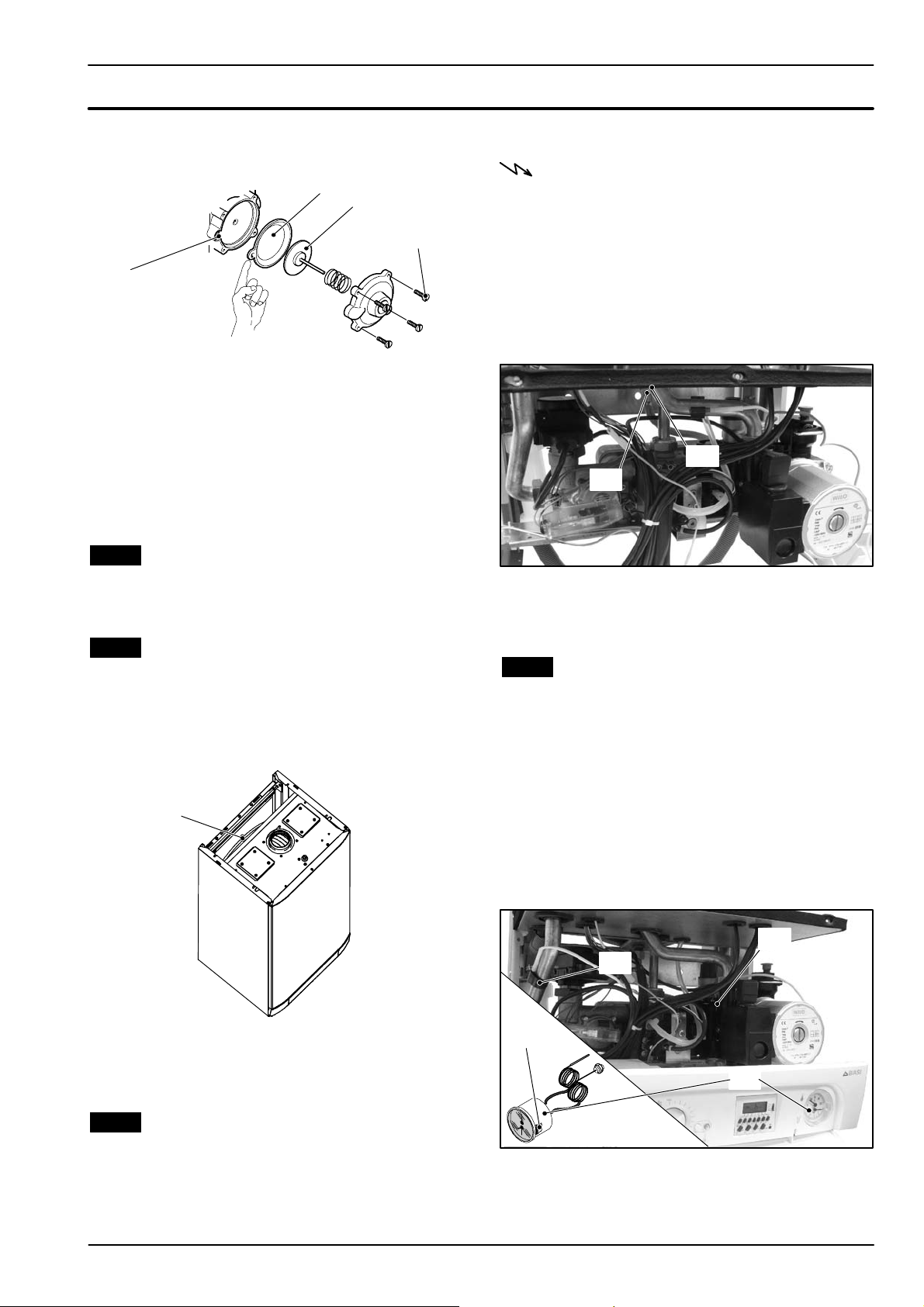
3 Unscrew the four screws E (see Fig. 12.5) open
the hydraulic operator and remove the membrane F.
F
G
E
H
Fig. 12.5
4 Reassemble the parts in reverse order of removal.
When assembling the membrane, ensure that its
concaveside faces towards the actuator plate G and
the reference indicated aligns with the seat H (see
Fig. 12.5).
13 Expansion vessel and
temperature---pressure gauge
13.1 Function
sion vessel can be changed without removing the
boiler.
Warning: isolate the boiler from the mains
electricity supply before removing any
covering or component.
1 Remove the front and left hand side panels of the
case, turn off the flow and return isolation valves
and empty the primary circuit.
2 Completely unscrew the connection K,thelock-
nut L (Fig. 13.2) and remove the expansion
vessel from the top of the boiler.
L
K
The Expansion vessel (I in Fig. 12.1) function is to allow
for the volume expansion of the c.h. circuit water due
to the temperature rise.
13.2 Checks
1 Turn off the flow and return isolation valves and
empty the primary circuit of the boiler.
2 Remove the protective cap J (Fig. 13.1) from the
valve on the top of t he expansion vessel and connect a suitable air pressure gauge.
I
Fig. 13.1
3 Check the pre--- load pressure and refer to the
section Expansion vessel in the User manual and
installation instructions for the correct value.
Fig. 13.2
3 Re --- assemble the parts in reverse order of re-
moval.
13.4 Removal of the temperature---pressure
gauge
1 Remove the front and right hand side panels of
the case, turn off the flow and return isolation
valves and empty the primary circuit.
2RemovetheforkM and the probe holder spring
N (Fig. 13.3).
3 Squeeze the tabs O to release the temperature ---
pressure gauge P and remove it.
4 Re --- assemble the parts in reverse order of re-
moval.
M
N
O
P
13.3 Removal of the expansion vessel
If there is at least 400 mm clearance above the boiler
and the rear exit flue can be easily removed, the expan-
Fig. 13.3
31
Page 34
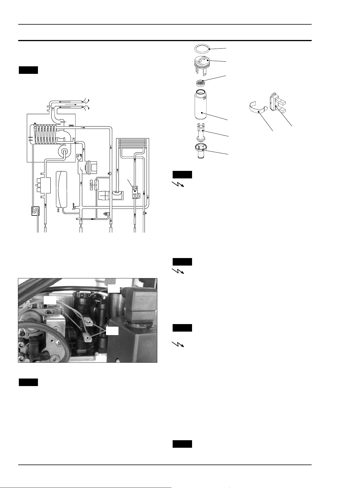
14 D.h.w. flow switch, filter and flow
limiter
14.1 Function
The d.h.w. flow switch A in Fig. 14.1 is a device that
generates an electrical signal when hot water is drawn.
2
1
3
4
A
Fig. 14.1
Whentheflowratethroughthed.h.w.circuitreaches
about 2,5 litres/min’, the float 5 (Fig. 14.3) is dragged
upwards and the magnetic in it, getting closer to the
sensor 8 closes the electric contact.
D
C
8
Fig. 14.3
5
6
7
14.3 Checks
Warning: isolate the boiler from the mains
electricity supply before removing any
covering or component.
n Sensor operation
1 Remove the front panel of the case.
2 Measure the electrical resistance at the leads of
the sensor. Without water being drawn, the contact must be open. By opening a hot water tap the
contact must be close (electrical resistance zero
8).
14.4 Removal of the sensor
Warning: isolate the boiler from the mains
electricity supply before removing any
covering or component.
1 Remove the front panel of the case.
2 D isconnect the connectors B and remove the
sensor holder spring C (Fig. 14.2).
3 Remove the sensor.
B
Fig. 14.2
14.2 Description and location of parts
(Fig. 14.3)
1 Flow switch plug
2 O --- r i n g
3 Flow limiter (M110B.32SM/... optional accessory)
4Body
5Float
6Filter
7 Sensor holder spring
8Sensor
32
14.5 Removal of the flow switch group and
d.h.w. circuit filter
Warning: isolate the boiler from the mains
electricity supply before removing any
covering or component.
1 Remove the front panel of the case and empty the
d.h.w. circuit.
2 Remove the sensor (see section 14.4).
3RemovetheforkD andpulluptheflowswitch
plug 1 with the help of a screwdriver.
4 To remove the filter from the flow switch group
separate the filter 6 from the body 4 (Fig. 14.3) by
levering it.
5 Reassemble the parts following the removing se-
quence in reverse order.
14.6 Flow limiter
The M110B.24SM/... model is factory fitted with a 10
litre/min. flow limiter.
Page 35
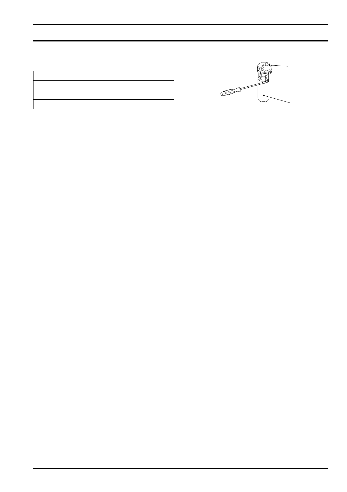
D.h.w. flow switch, filter and flow limiter
If on the M110B.32SM/... model the flow rate of the
d.h.w. circuit is too high, it is possible to limit it by installing a flow limiter. The following sizes are available:
Nominal flow rate (litres/min)
Colour
10 Blue
12 Red
14 Pink
To in st a ll t h e f l o w l i m it e r:
1 Remove the flow switch group as explained in the
section 14.5.
2 Separate the flow switch plug 1 from the body 4
levering with a screwdriver one of the two hooks.
1
4
Fig. 14.4
3 Insert the flow limiter 3 as shown in Fig. 14.3
4 Reassemble the group following the above se-
quence in reverse order.
33
Page 36
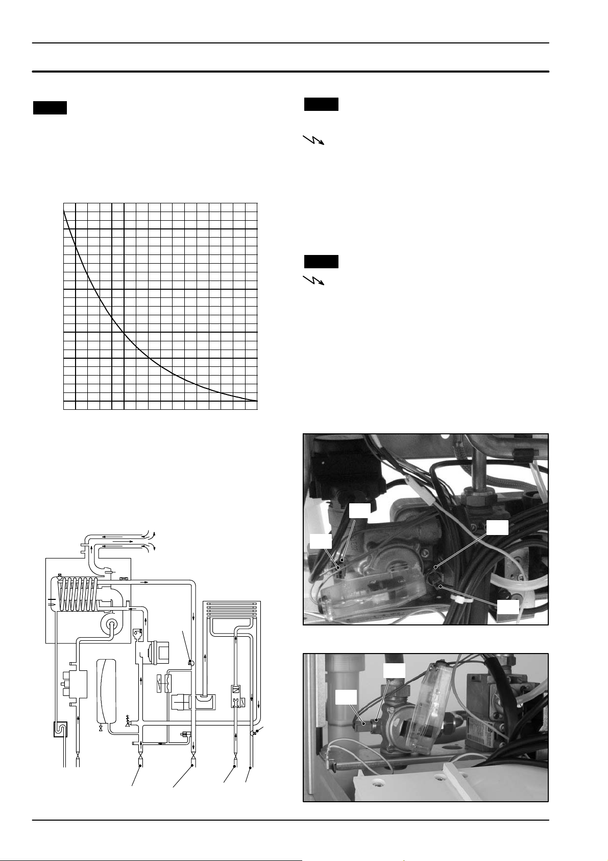
15 Te m p e r a t u r e pr o b e
15.1 Function
The Temperature probe has the function of converting
the temperature of the water in the hydraulic circuit
where it is installed into an electrical signal (resistance).
The relation between temperature and electrical resistance is stated in Fig. 15.1.
8
12500
12000
11500
11000
10500
10000
9500
9000
8500
8000
7500
7000
6500
6000
5500
5000
4500
4000
3500
3000
2500
2000
1500
1000
500
20 25 30 35 40 45 50 55 60 65 70 75 80 85 90 95 100
Fig. 15.1
˚C
15.2 Checks
n Temperature --- resistance relationship
Warning: isolate the boiler from the mains
electricity supply before removing any
covering or component.
Disconnect the cable from the Temperature probe.
Measure the temperature of the pipe near the Temperature probe and check the electrical resistance according to the graph in Fig. 15.1.
15.3 Removal of the c.h.Temperature probe
Warning: isolate the boiler from the mains
electricity supply before removing any
covering or component.
1 Removeallthecasepanelsandthesealed
chamber lid.
2 Empty the primary circuit of the boiler.
3 Remove the electric connector C and unscrew
the c.h. Temperature probe A --- F i g . 1 5 . 3 o r
Fig. 15.4
4 Reassemble the c.h.Temperature probe carrying
out the removal operations in reverse order.
On the boiler there are two Temperature probes. One
on the output of the primary condensing heat exchanger (c. h. Temperature probe) A in Fig. 15.2 and
Fig. 15.3; one on the output of the d.h.w. heat exchanger (d.h.w. Temperature probe) B in Fig. 15.2 and
Fig. 15.3.
A
B
A
B
C
D
Fig. 15.3
A
C
Fig. 15.2
34
c.h.
return
c.h.
flow
d.h.w.
inlet
d.h.w.
outlet
Fig. 15.4
Page 37

Temp e rat ure pro b e
15.4 Removal of the d.h.w.Temperature probe
Warning: isolate the boiler from the mains
electricity supply before removing any
covering or component.
1 Remove the front panel of the case.
2 Empty the d.h.w circuit of the boiler.
3 Remove the electric connector D and unscrew
the d.h.w. Temperature probe B --- F i g . 1 5 . 3
4 Reassemble the d.h.w. Temperature probe carry-
ing out the removal operations in reverse order.
Warning: to lubricate the O-- ring gaskets
exclusively use a silicone base grease
compatible to be in contact with foods and
approved by the local water Authorities.
35
Page 38
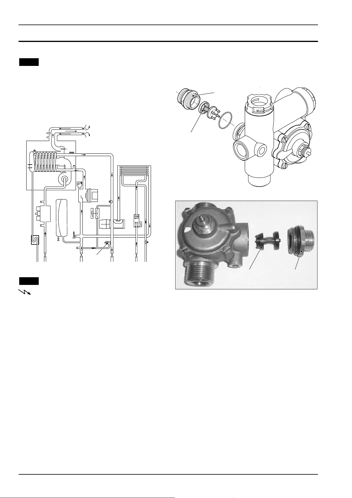
16 B y --- pa s s v a l v e
16.1 Function
The By---pass valve A in Fig. 16. 1 is located between
the c.h. water flow and return and its function is that of
guaranteeing a minimum flow across the primary heat
exchanger if the circulation across the c.h. system is
completely closed.
The By ---pass valve is fitted on the rear side of the diverter group.
2 Empty the primary circuit of the boiler.
3 Remove the diverter group as described in the
section 8.4 of this manual.
4 Unscrew the connector B and remove the by ---
pass valve C (Fig. 16.2) (Fig. 16.3).
B
C
Fig. 16.2
A
Fig. 16.1
16.2 Removal
Warning: isolate the boiler from the mains
electricity supply before removing any
covering or component.
1 Removeallthecasepanels.
C B
Fig. 16.3
5 Reassemble the by --- pass valve as illustrated in
Fig. 16.2 --- Fig. 16.3 reversing the order of removal.
36
Page 39
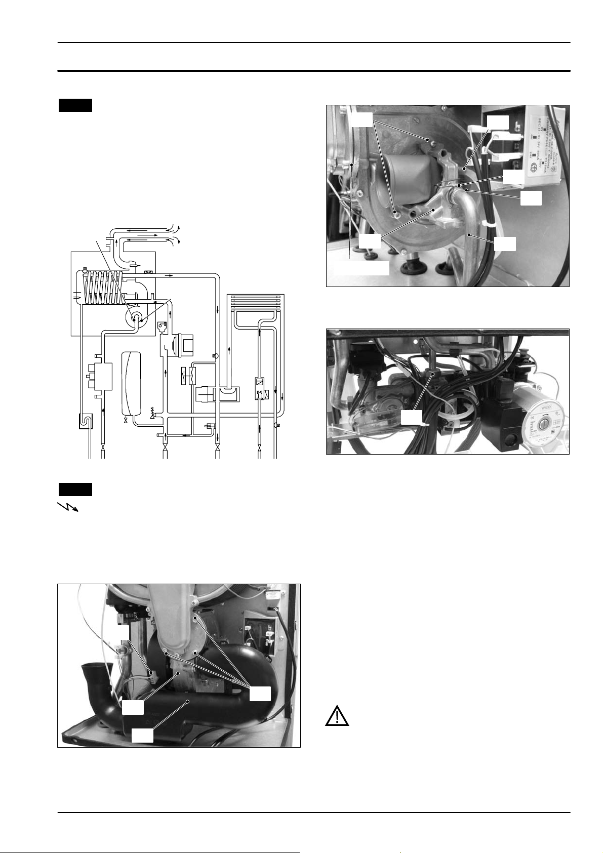
17 Fan and Air box
17.1 Function
The function of the Fan A (Fig. 17.1) is to force the mixture of air and gas into the burner.
The function of the Air box B is to mix the gas and the
air in the right proportion.
The flow rate of the air--- gas mixture and consequently
the input power of the boiler is proportionalto the speed
of the fan that is controlled by the electronic control
p.c.b.
3 Disconnect the air manifold C (Fig. 17.2) by pul-
ling it.
I
D
F
H
A
B
Fig. 17.1
17.2 Removal of the Air box and the Fan
Warning: isolate the boiler from the mains
electricity supply before removing any
covering or component.
1 Turn off the gas supply.
2 Removeallthecasepanelsandthesealed
chamber lid (see section 2).
K
J
Fan g asket
Fig. 17.3
G
4 D isconnect the rubber pipe D (Fig. 17.3).
E
Fig. 17.4
5 Unscrew the gas connector E (Fig. 17.4)
6 Remove the fixing fork F andremovethegaspipe
G (Fig. 17.3).
7 Loosen without removing the screw H.
8RemovethescrewsI and the air box J.Leavethe
air box with the air manifold clamped to the water
pipe.
9 D isconnect the fan connector K by pressing the
plastic hook placed on the side of the connector
(Fig. 17.2).
10 Unscrew the screws L (Fig. 17.2).
11 Remove the fan M.
12 Assemble the Fan and the Air box carrying out
the removal operations in reverse sequence.
Fig. 17.2
Before reassembling ensure the fan gasket
L
M
(Fig. 17.3) is correctly mounted.
Warning: After cleaning or replacement as
detailed above, if it deemed necessary to
C
undertake a combustion analysis, refer to
the appropriate chapter Maintenance of the
installation instructions manual.
37
Page 40
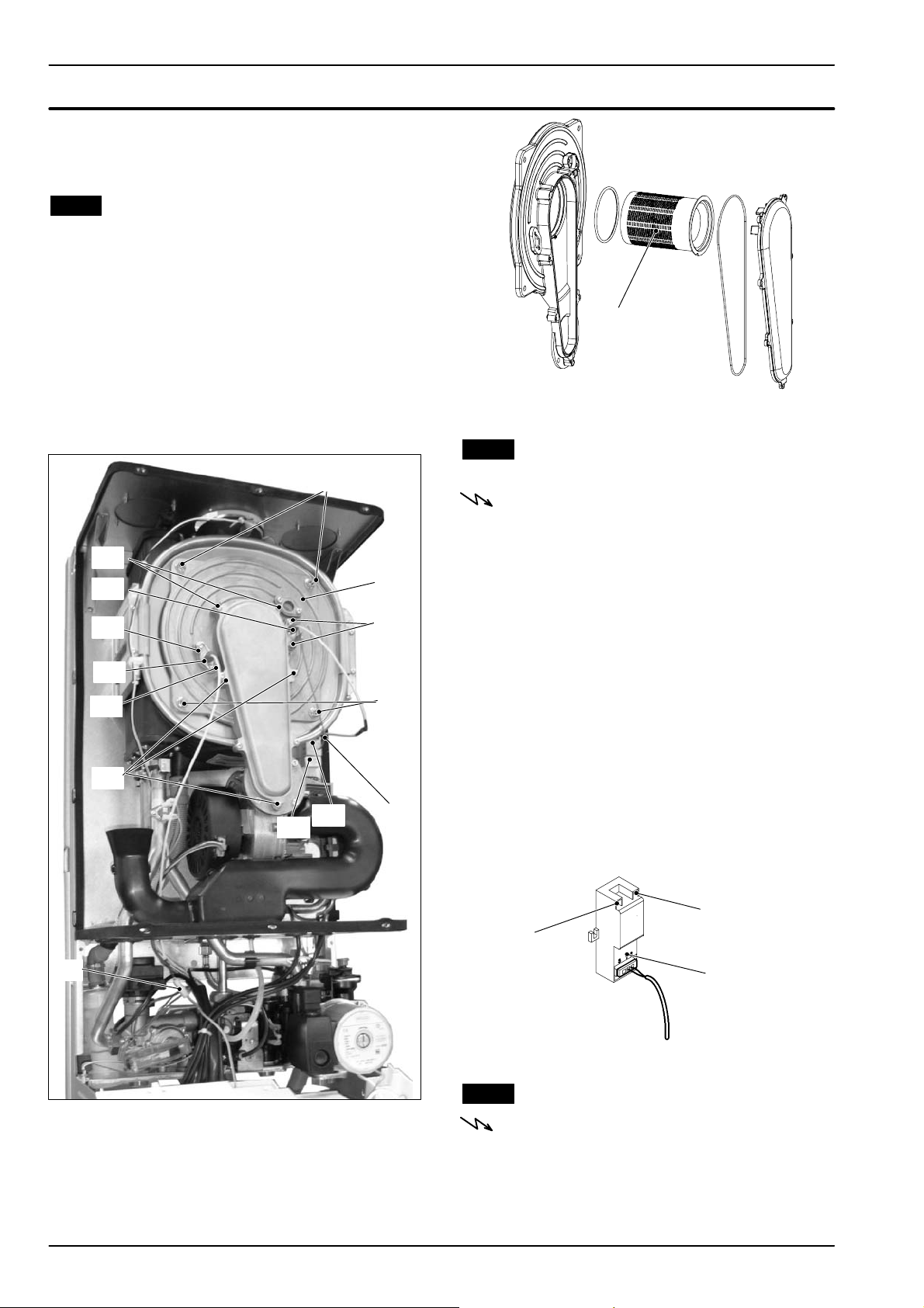
18 Ignition and detection electrodes,
burner and spark generator
18.1 Function
Three electrodes are fitted on the fan --- burner group.
Two of them, fitted on the right side of the fan--- burner
group A, are the ignition electrodes B and are connected to the spark generator C.
On the left side is the detection electrode D and it detects the presence of the flame.
J
K
B
I
D
I
K
A
I
J
E
Fig. 18.2
18.2 Removal of the Ignition and detection
electrodes
Warning: isolate the boiler from the mains
electricity supply before removing any
covering or component.
1 Removeallthecasepanelsandthesealed
chamber lid (see section 2) .
2 D isconnect the ignition electrodes connector F
and the earth wire G from the spark generator C
(Fig. 18. 1) and disconnect the detection electrode connector H.
3 Unscrew the screws I andremovetheignition
electrodes B and the detection electrode D
(Fig. 18.1).
4 Assemble the Ignition and detection electrodes
carrying out the removal operation in reverse order.
C
H
Fig. 18.1
GF
The burner E is fitted on the rear of the fan ---burner
group A.
38
When reassembling the ignition electrodes be sure
to connect correctly the wires to the spark generator (see Fig. 18.3)
earth wire
ignition electrodes
wire
C
Fig. 18.3
18.3 Removal of the burner
Warning: isolate the boiler from the mains
electricity supply before removing any
covering or component.
1 Remove the air box and the fan (see section 17.2)
2 Remove the Ignition and detection electrodes
(see section 18.2).
Page 41
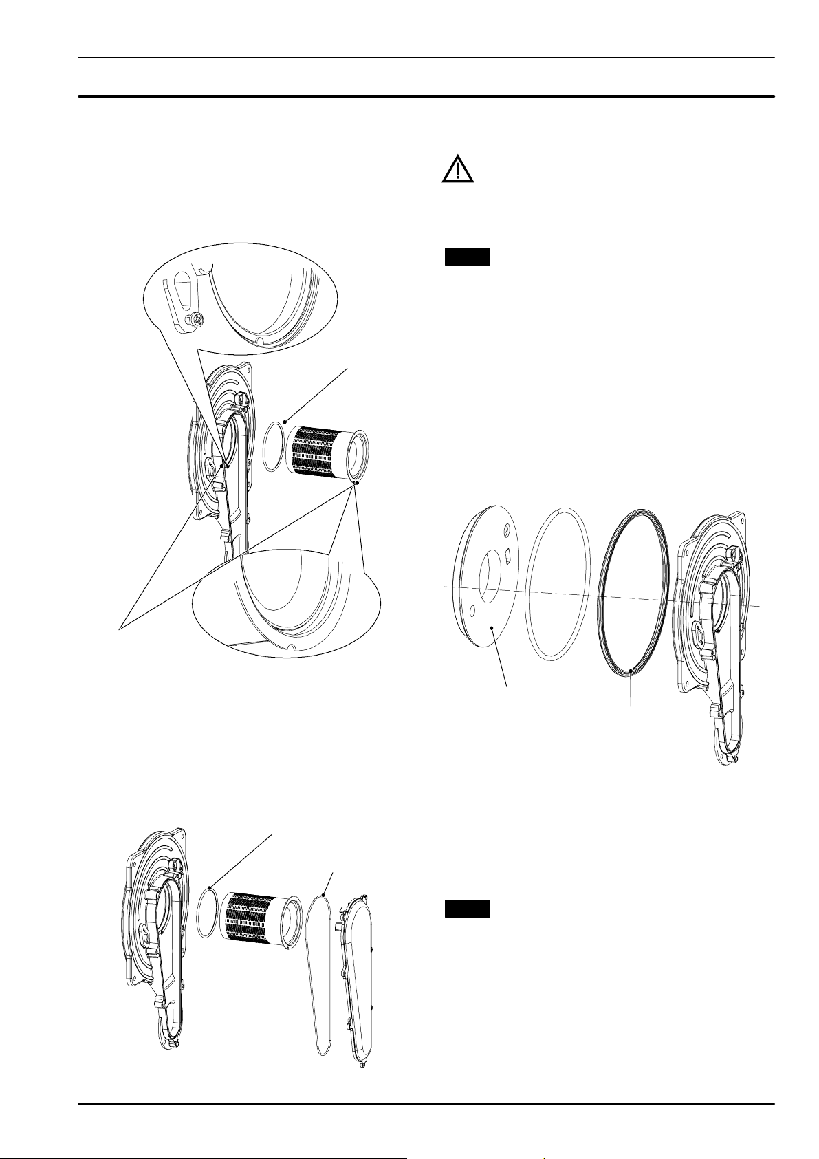
Ignition and detection electrodes
t
3 Unscrew the screws J (Fig. 18.1 )and remove the
cover of the combustion chamber.
4 Unscrew the screws K (Fig. 18.1 ) and remove the
A i r --- g a s d u c t li d .
5 Remove the burner by sliding it forward.
burner gaske
Before reassembling ensure the burner gasket is
correctly located.
Warning: After cleaning or replacement as
detailed above, if it deemed necessary to
undertake a combustion analysis, refer to
the appropriate chapter Maintenance of the
installation instructions manual.
18.4 Removal of the front insulation panel
See warning note at the end of this chapter before
toremovethispart.
1 Remove the Ignition and detection electrodes
(see section 18.2).
2 Remove the burner (see section 18.3).
3Removethe
4 Assemble the new front insulation carrying out
the removal operation in reverse order.
When fitting the new panel ensure that the electrodes holes coincide with the holes of the combustion chamber.
front insulation panel (Fig. 18.6).
locating tab
Fig. 18.4
6 Assemble the burner carrying out the removal
operation in reverse order. Ensure the burner is
correctly located by lining up the locating tab
(Fig. 18.4).
burner gasket
A i r --- g a s d u c t g a s k e t
Fig. 18.5
front insulation
Siliconic gasket
Fig. 18.6
The siliconic gasket (Fig. 18.6) must be replaced if
damaged or anyway every 2 years.
The front insulation (Fig. 18.6) must be replaced if
damaged or wet
18.5 Removal of the rear insulation
See warning note at the end of this chapter before
toremovethispart.
Attention: Cover the inner of the condensing heat
exchanger to avoid that dirt and debris fall in the
coil.
1 Do the operations of section 18.3 from step 1 to
step 3.
2 Unscrew the screw L, remove the washer M and
the rear insulation N (Fig. 18.7).
39
Page 42
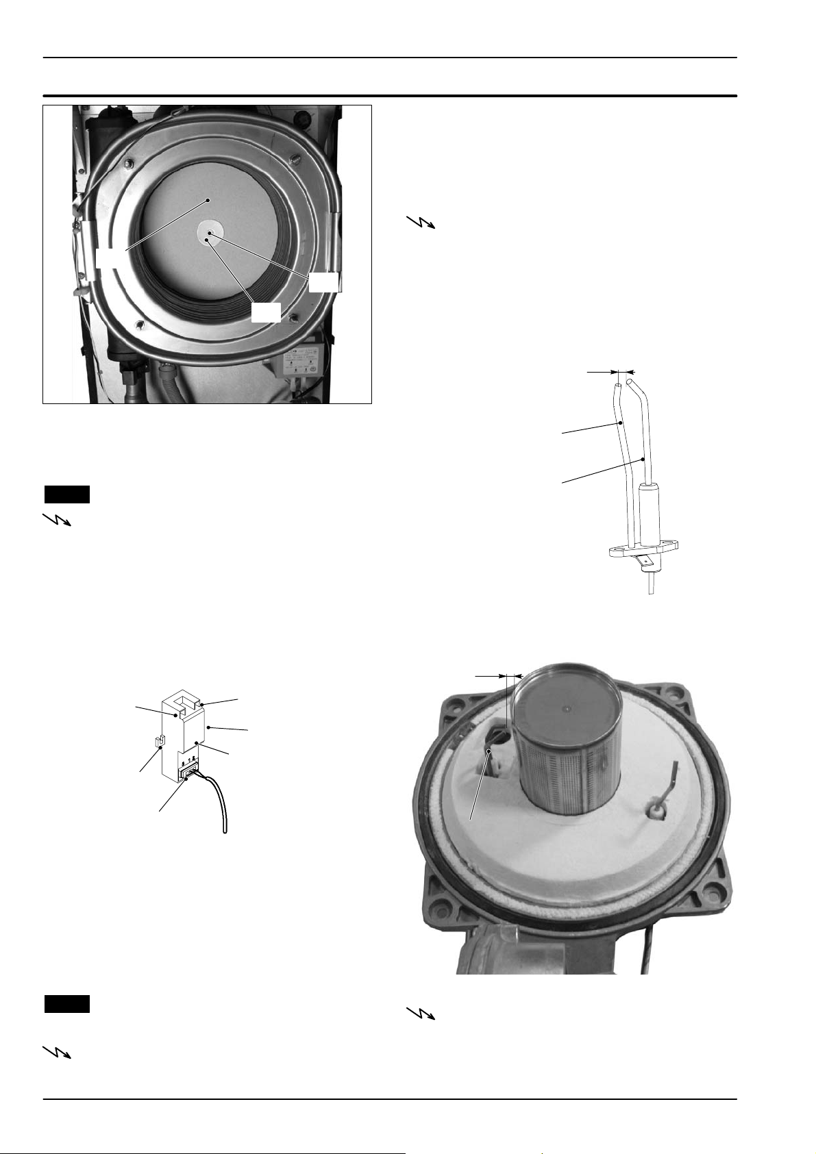
Ignition and detection electrodes
N
L
M
Fig. 18.7
The rear insulation (Fig. 18.7) must be replaced if
damaged or wet
There is not a significant way to verify the integrity of the
spark generator.
When the fan turns but the burner does not light a possible cause is a faulty spark generator and it is advisable
to replace it to locate the fault.
n Check the position of the electrode edges
Warning: isolate the boiler from the mains
electricity supply before removing any
covering or component.
1 Remove the ignition electrodes (see section 18.2)
2 Check for the correct distance between the me-
tallic edges of the ignition electrode (see Fig. 18.9
--- Fig. 18.10).
3,5 mm
earth electrode
18.6 Removal of the spark generator
Warning: isolate the boiler from the mains
electricity supply before removing any
covering or component.
1 Removeallthecasepanelsandthesealed
chamber lid.
2 D isconnect the spark generator connector
coming from the control p.c.b, the electrodes wire
and the earth wire coming from the ignition electrodes (Fig. 18.8).
ignition electrodes
wire
O
earth wire
O
C
spark generator
connector
Fig. 18.8
3 Unscrew the screws O and remove the spark
generator
.
4 Assemble the spark generator carrying out the re-
moval operation in reverse order.
When reassembling the spark generator be sure to
connect correctly the wires.
18.7 Checks
n Check of the spark generator
Warning: isolate the boiler from the mains
electricity supply before removing any
covering or component.
40
Ignition electrode
Fig. 18.9
n Check the connection wires.
7mm
Ignition electrode
Fig. 18.10
Warning: isolate the boiler from the mains
electricity supply before removing any
covering or component.
1 Removeallthecasepanelsandthesealed
chamber lid.
Page 43

Ignition and detection electrodes
2 Check for the integrity of the insulation of wires
which connect the electrodes to the spark generator and to the control/ignition p.c.b.
Warning -- Insulation panels material handling care
Mineral fibres are used in this appliance for the insulation panels of the combustion chamber
Excessive exposure to these materials may cause temporary irritation to eyes, skin and respiratory tract.
Known hazards --- Some people can suffer reddening
and itching of the skin. Fibre entry into the eye will
cause foreign body irritation, which can cause severe
irritation to people wearing contact lenses. Irritation to
respiratory tract.
Precautions --- Dust goggles w ill protect eyes. People
with a history of skin complaints may be particularly
susceptible to irritation. High dust levels are only likely
to arise following harsh abrasion. In general, normal
handling and use will not present high risk, follow good
hygiene practices, wash hands before, touching eyes,
consuming food, drinking or using the toilet.
Firstaid---Medicalattentionmustbesoughtfollowing
eye contact or prolonged reddening of the skin.
41
Page 44
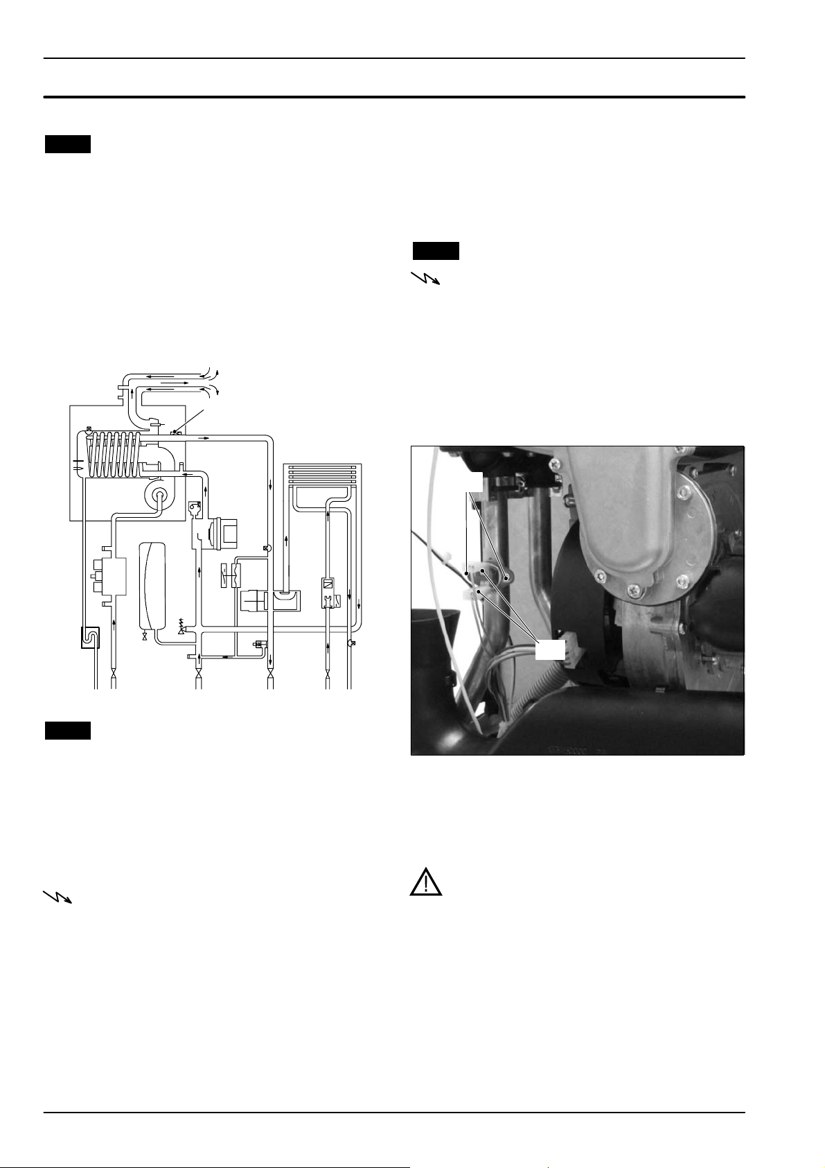
19 Safety thermostat
19.1 Function
The safety thermostat A in Fig. 19.1 is a device that
senses the temperature of the primary circuit water
which flows in the outlet pipe of t he condensing heat exchanger.
If the temperature control system of the boiler fails and
the temperature of the primary circuit reaches a dangerous temperature, the safety thermostat opens the
electric circuit that supplies the on--- off operators of the
gas valve.
Consequently, the full sequence ignition device attempts to light the burner and, at the end, locks the
boiler and lights the lock--- out signal lamp.
A
n Electrical function
1 Removeallthecasepanelsandthelidofthe
sealed chamber.
2 D isconnect the safety thermostat and check its
electrical function. Normally (no intervention) the
contact must be closed (electrical resistance zero
8).
19.3 Removal
Warning: isolate the boiler from the mains
electricity supply before removing any
covering or component.
1 Removeallthecasepanelsandthelidofthe
sealed chamber.
2 Disconnect the wiring B (detail in Fig. 19.2).
3 Unscrew the screws C which hold the overheat
thermostat on the pipe of the condensing heat exchanger and remove it.
C
Fig. 19.1
19.2 Checks
n Overheat temperature value
1 Set the temperature control knobs to their max.
position and run the boiler in d.h.w. and c.h.
2 Allow the boiler to reach its maximum operating
temperature (monitor the temperature gauge on
the instrument panel). The boiler should maintain
a temperature below that of the safety thermostat
and no overheat intervention should occur.
Warning: isolate the boiler from the mains
electricity supply before removing any
covering or component.
B
Fig. 19.2
4 Reassemble the overheat thermostat carrying out
the operations in reverse order.
5 Apply an adequate quantity of heat conducting
compound between the pipe and the thermostat.
Warning: After cleaning or replacement as
detailed above, if it deemed necessary to
undertake a combustion analysis, refer to
the appropriate chapter Maintenance of the
installation instructions manual.
42
Page 45
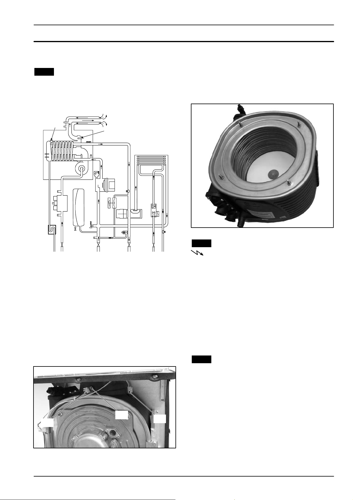
20 Flue temperature probe NTC and
Safety thermal fuse
20.1 Function
The Flue t emperature probe NTC A in Fig. 20.1 and
Fig. 20.2 senses the temperature of the combustion
products that flow through the condensing heat exchanger.
B
A
NTC and acts as a safety device in extreme case of incorrect operation of the Flue temperature control system.
Reaching the breakdown temperature it opens the circuit and locks out the boiler.
In case of intervention of this safety device the heat ex changer (part shown in Fig. 20.3) may be damaged
and must be replaced.
Fig. 20.1
If the temperature of the combustion products circuit
reaches the limit temperature, the Flue temperature
probe NTC reduces the gas flow rate to the burner. The
temperature of the combustion products should decrease to a safe value temperature.
In the case that the temperature of the combustion
products reaches a potentially dangerous value, it
stops the boiler operation (lock--- out).
This allows the use of plastic materials for the flue outlet
pipes and bends.
The use of kits different from the original isn’t however
allowed, since the flue pipes are integral parts of the
boiler.
A
C
Fig. 20.2
B
ASafetythermalfuse B in Fig. 20.1 --- Fig. 20.2 is also
connected in series with the Flue temperature probe
Fig. 20.3
20.2 Removal
Warning: isolate the boiler from the mains
electricity supply before removing any
covering or component.
1 Removeallthecasepanelsandthesealed
chamber lid.
2 D isconnect the connector C from the Flue tem-
perature probe NTC by pressing the plastic hook
placed on the side of the connector.
3 Unscrew and remove the flue temperature probe
A (Fig. 20.2) from the condensing heat exchanger.
4 Assemble the Flue temperature probe NTC carry-
ing out the removal operations in reverse sequence.
20.3 Checks
n Overheat temperature value
1 Set the temperature control knobs to their max.
position and run the boiler in d.h.w. and c.h.
2 Allow the boiler to reach its maximum operating
temperature (monitor the temperature gauge on
the instrument panel). The boiler should maintain
a temperature below that of the Flue temperature
probe NTC and no overheat intervention should
occur.
n Temperature --- resistance relationship
1 Remove the Flue temperature probe NTC (see
section 20.2).
2 Measure the Flue temperature probe NTC electri-
cal resistance at the ambient temperature and
check it according to the graph in Fig. 20.4
43
Page 46
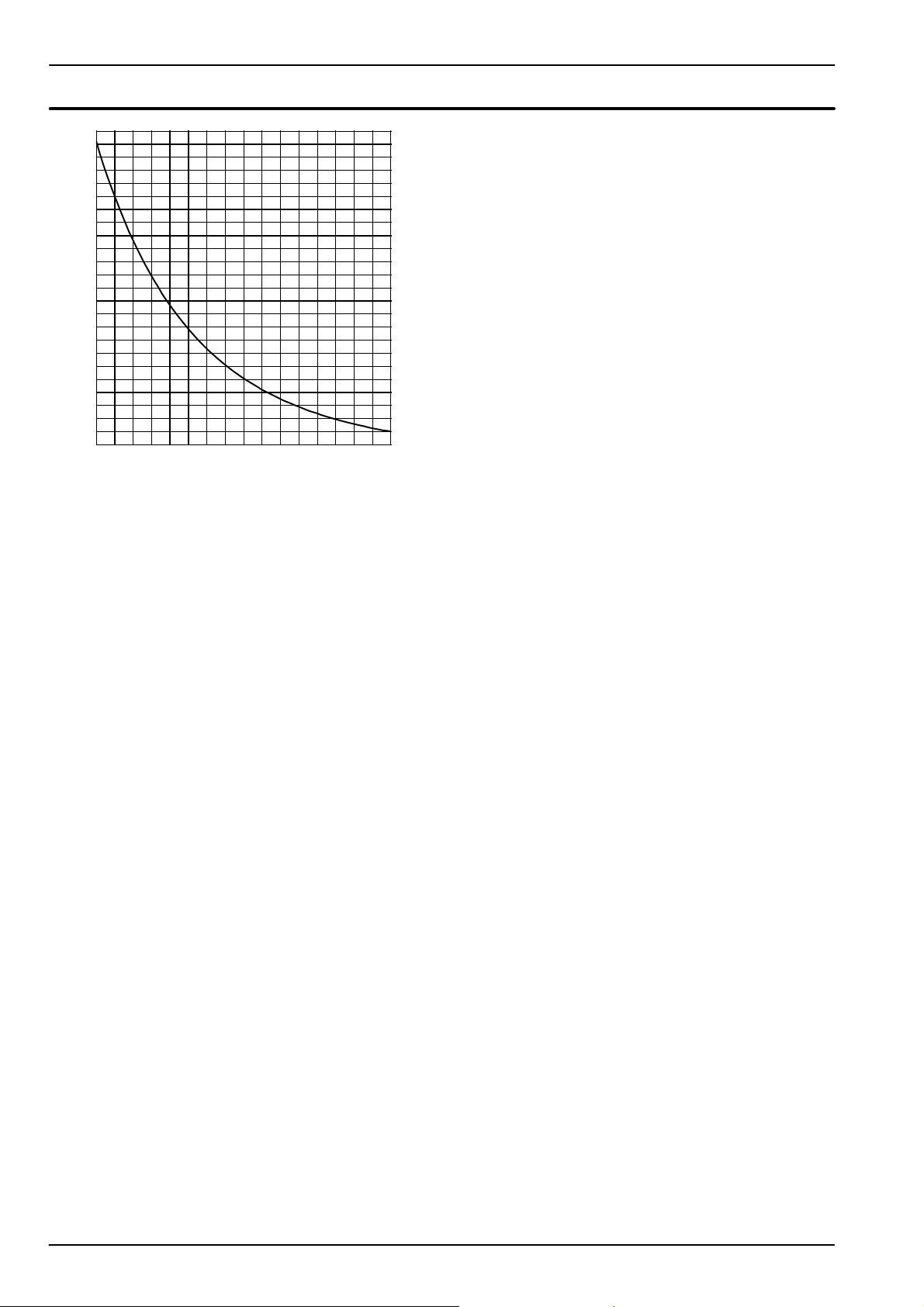
Flue thermostat
8
12500
12000
11500
11000
10500
10000
9500
9000
8500
8000
7500
7000
6500
6000
5500
5000
4500
4000
3500
3000
2500
2000
1500
1000
500
20 25 30 35 40 45 50 55 60 65 70 75 80 85 90 95 100
Fig. 20.4
˚C
44
Page 47
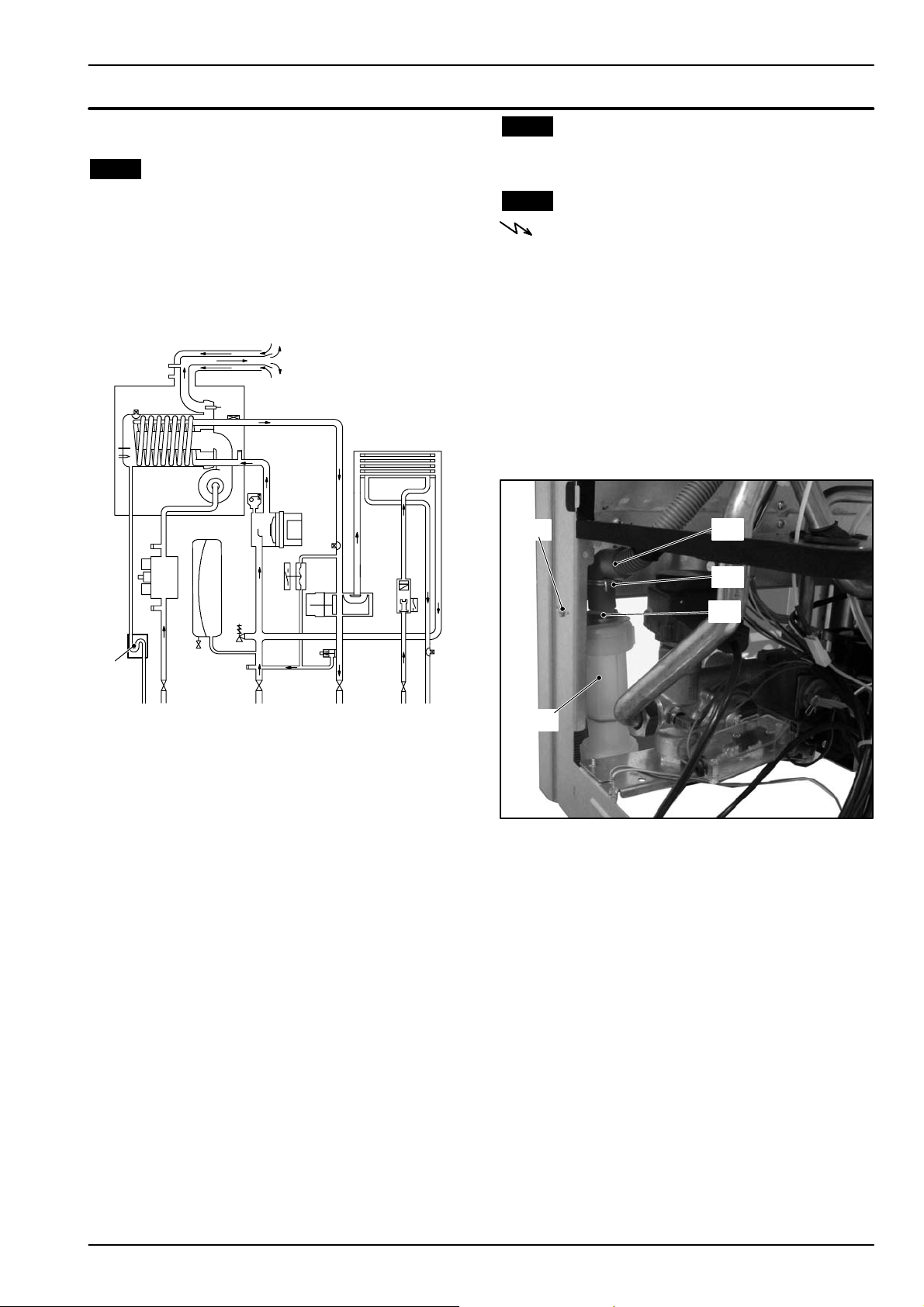
21 Condensate trap
21.1 Function
21.2 Check the cleanness of the trap
Unscrew the plug on the bottom of the trap and remove
dirt eventually deposit.
The condensate trap A in Fig. 21.1 and Fig. 21.2 allows
the discharge of the condensate via the condensate
drain pipe avoiding in the mean time the escape of
combustion products.
A plastic ball closes the trap outlet in case that the trap
is empty.
21.3 Removal
Warning: isolate the boiler from the mains
electricity supply before removing any
covering or component.
1 Remove the front and left case panels.
2 D isconnect the trap from the draining pipe.
3 Using pliers, remove the spring B moving it up-
wards and remove the flexible pipe C.
4 Unscrew the screw D and remove the trap.
5 Unscrew the lock ---nut E and separate the trap
from its bracket.
6 Reassemble carrying out the removal operations
in reverse order.
D
C
B
E
A
Fig. 21.1
If the drain pipe is plugged or in any case in which the
condensate isn’t correctly evacuated, the condensate
level in the trap rises till it reaches the detection electrode in the combustion chamber thus causing the
boiler lock---out.
A
Fig. 21.2
45
Page 48
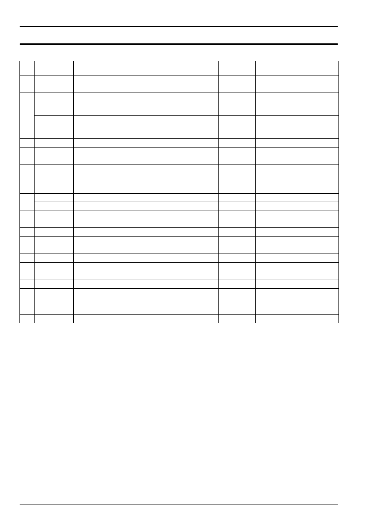
22 Short spare parts list
Key G.C. part no. Description Q.ty Manufac-
turer part no.
1
H 5 8 --- 6 8 8 Burner (mod. M110B.24SM/... M110B.24SR/...) 1 BI1293 100
H 5 8 --- 6 8 9 Burner (mod. M110B.32SM/...) 1 BI1293 101
2 E94 ---576 Expansion vessel 1 BI1182 105 CIMM 7 litres
3
H 5 8 --- 6 5 9 Condensing heat exchanger (mod.
M110B.24SM/... M110B.24SR/...)
H 5 8 --- 6 6 0 Condensing heat exchanger (mod.
M110B.32SM/...)
4 H 5 8 --- 7 0 2 Fan 1 BI1293 105 EBM RG128 24V 54W
5 H 5 8 --- 6 9 4 Gas valve 1 BI1293 104 SIT 848 Sigma
6 H 5 0 --- 1 8 9 Safety valve 1 BI1181 100 Watts
7
H 5 8 --- 7 1 7 Electronic regulation p.c.b. (mod.
M110B.24SM/... M110B.24SR/...)
H 5 8 --- 7 1 8 Electronic regulation p.c.b. (mod.
M110B.32SM/...)
8
E01 --- 205 D.h.w. heat exchanger (M110B.24SM/...) 1 BI1001 102
H 0 5 --- 1 6 1 D.h.w. heat exchanger (M110B.32SM/...) 1 BI1161 100
9 H 5 8 --- 6 7 0 Pump 1 BI1911 103
10 H 3 2 --- 5 5 5 Primary circuit flow switch 1 BI1251 501
11 169--- 010 D.h.w. flow switch 1 KI1042 107
12 E00---688 Main. flow switch membrane 1 BI1011 103
13 E83---086 Three way diverter valve (electric actuator) 1 BI1101 102 Elbi
14 E83---101 Overheat thermostat 1 BI1172 105 E L T H --- t y p e 2 6 1
15 H 5 8 --- 6 6 1 Flue temperature probe NTC 1 BI1432 102
16 H 4 4 --- 1 7 0 Fuse 3,15 AF 2 BI1295 108
17 Fuse 400 mA T 1 BI1665 104
18 164--- 026 Temperature probe (main or D.h.w. circuit) 2 KI1001 117
19 H 5 8 --- 7 0 9 Detection electrode 1 BI1293 103
20 H 5 8 --- 6 8 0 Ignition electrode 1 BI1293 102
21 E83---145 Temperature --- pressure gauge 1 BI1475 108 IMIT
1 BI1432 100
1 BI1432 101
1 BI1955 100
1 BI1955 101
Manufacturer’s reference
Orkly (alternative)
Bertelli & Partners
46
Page 49
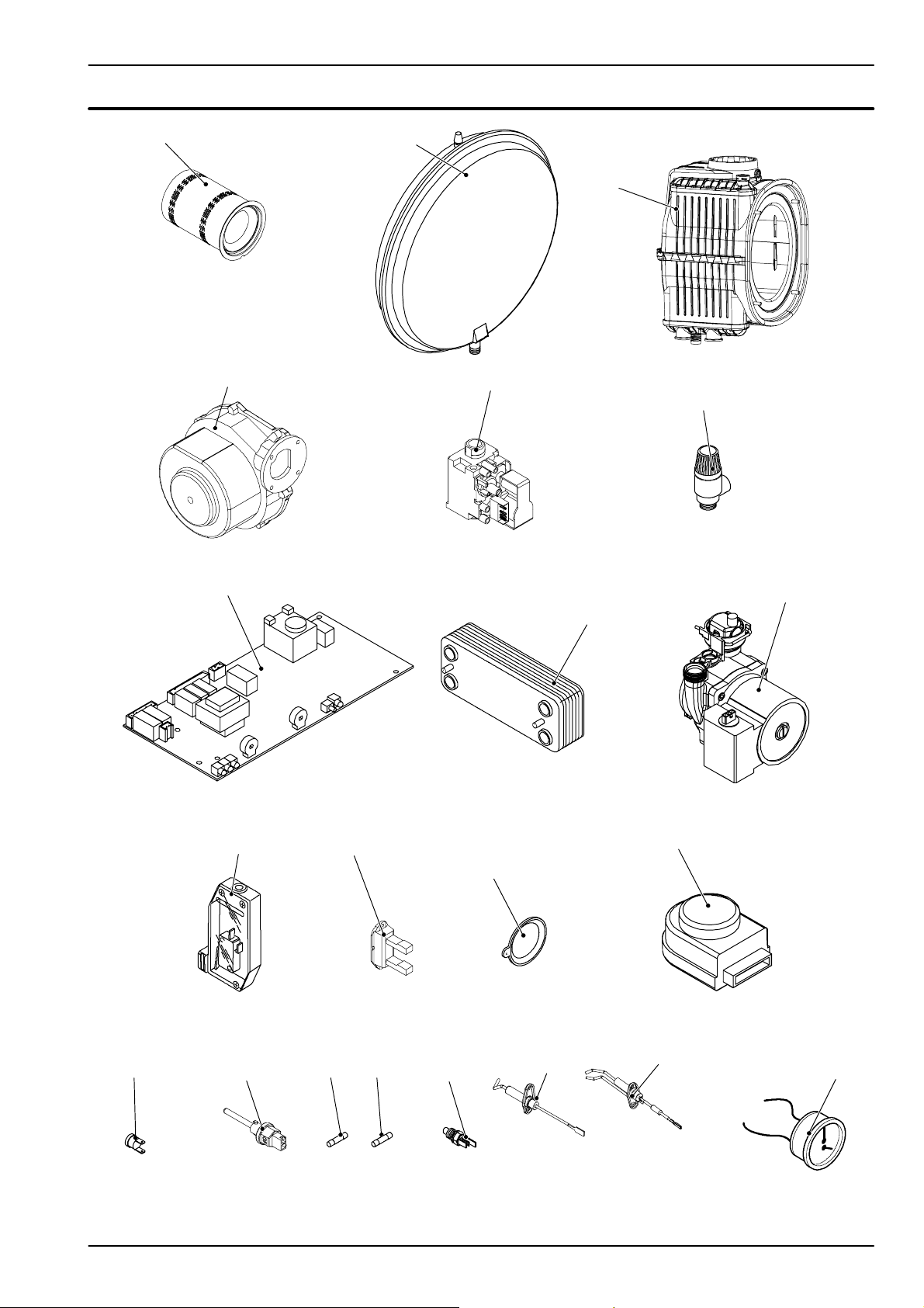
Short spare parts list
1
4
2
3
5
6
7
8
P5
10
11
12
13
9
14 16
15
17
18
19
20
21
47
Page 50

Page 51

Page 52

*1796213402*
17962.1340.2 2008 52A4 UK
14/05
2008
1
Biasi UK Ltd
Newman Park, Western Way
Wednesbury, WS10 7BJ
Sales Tel No: 0121 506 1340
Sales Fax No: 0121 506 1360
Service Tel No: 0121 506 1350
Service Fax No: 0121 506 1370
www.biasi.co.uk
 Loading...