

Page 1

®
Vocia
VO-4
Operation Manual
Biamp Systems, 10074 S.W. Arctic Drive, Beaverton, Oregon 97005 U.S.A. (503) 641-7287 www.biamp.com
Page 2

TABLE OF CONTENTS
VOCIA OUTPUT 4 (VO-4) FEATURES . . . . . . . . . . . . . . . . . . . . . . . . . . . . . . . . . . . . . . . . . . . . . . . . . . . . . . . . . 3
FRONT PANEL . . . . . . . . . . . . . . . . . . . . . . . . . . . . . . . . . . . . . . . . . . . . . . . . . . . . . . . . . . . . . . . . . . . . . . . . . . . . . . . . . . . . 4
Setup and Use . . . . . . . . . . . . . . . . . . . . . . . . . . . . . . . . . . . . . . . . . . . . . . . . . . . . . . . . . . . . . . . . . . . . . . . . . . . . . . . . . . . . . 4
1. Power Indicator LED ..............................................................................4
2. Signal LEDs . . . . . . . . . . . . . . . . . . . . . . . . . . . . . . . . . . . . . . . . . . . . . . . . . . . . . . . . . . . . . . . . . . . . . . . . . . . . . . . . . . . . . 4
3. Control LEDs . . . . . . . . . . . . . . . . . . . . . . . . . . . . . . . . . . . . . . . . . . . . . . . . . . . . . . . . . . . . . . . . . . . . . . . . . . . . . . . . . . . . 4
REAR PANEL CONTROLS . . . . . . . . . . . . . . . . . . . . . . . . . . . . . . . . . . . . . . . . . . . . . . . . . . . . . . . . . . . . . . . . . . . . 5-7
Device ID . . . . . . . . . . . . . . . . . . . . . . . . . . . . . . . . . . . . . . . . . . . . . . . . . . . . . . . . . . . . . . . . . . . . . . . . . . . . . . . . . . . . . . . . . 5
CobraNet . . . . . . . . . . . . . . . . . . . . . . . . . . . . . . . . . . . . . . . . . . . . . . . . . . . . . . . . . . . . . . . . . . . . . . . . . . . . . . . . . . . . . . . . . 5
Network Connection . . . . . . . . . . . . . . . . . . . . . . . . . . . . . . . . . . . . . . . . . . . . . . . . . . . . . . . . . . . . . . . . . . . . . . . . . . . . . . .5-6
Control Outputs ....................................................................................7
Control Inputs . . . . . . . . . . . . . . . . . . . . . . . . . . . . . . . . . . . . . . . . . . . . . . . . . . . . . . . . . . . . . . . . . . . . . . . . . . . . . . . . . . . . . 7
Audio Inputs .......................................................................................7
Ground Screw . . . . . . . . . . . . . . . . . . . . . . . . . . . . . . . . . . . . . . . . . . . . . . . . . . . . . . . . . . . . . . . . . . . . . . . . . . . . . . . . . . . . . 7
INSTALLATION ....................................................................................8
SPECIFICATIONS & BLOCK DIAGRAM .......................................................9
WARRANTY . . . . . . . . . . . . . . . . . . . . . . . . . . . . . . . . . . . . . . . . . . . . . . . . . . . . . . . . . . . . . . . . . . . . . . . . . . . . . . . . . . . . . .10
2
Page 3
VOCIA OUTPUT 4 (VO-4)
Power/
Network
Audio Cha nnel Control Input sControl Output s
Output 4
1
2341234
1 234
®
The VO-4 is a networked audio output expansion device allowing the user to add four line-level output channels to a Vocia
accepts four channels of digital audio input via CobraNet® and provides four line-level analog audio outputs. The VO-4 features embedded
DSP and on-board memory to process and store all device-specic conguration information locally and includes comprehensive, xed-chain,
digital-signal processing. As part of the Vocia system, the VO-4 meets paging requirements for facilities of all sizes.
system. The VO-4
FEATURES
Converts digital to analog•
Four removable terminal block connectors for line-level outputs•
Four control inputs and four control outputs•
Software-congurable local audio signal processing, including gain, lters, and compressor/limiter•
Rotary switches for unit identication•
Power Over Ethernet (PoE)•
CobraNet audio/control with dynamic use of available bundles, plus power over single Ethernet cable•
Status LEDs to indicate signal and clip•
CE• marked and RoHS compliant
Covered by • BIAMP Systems’ warranty
3
Page 4
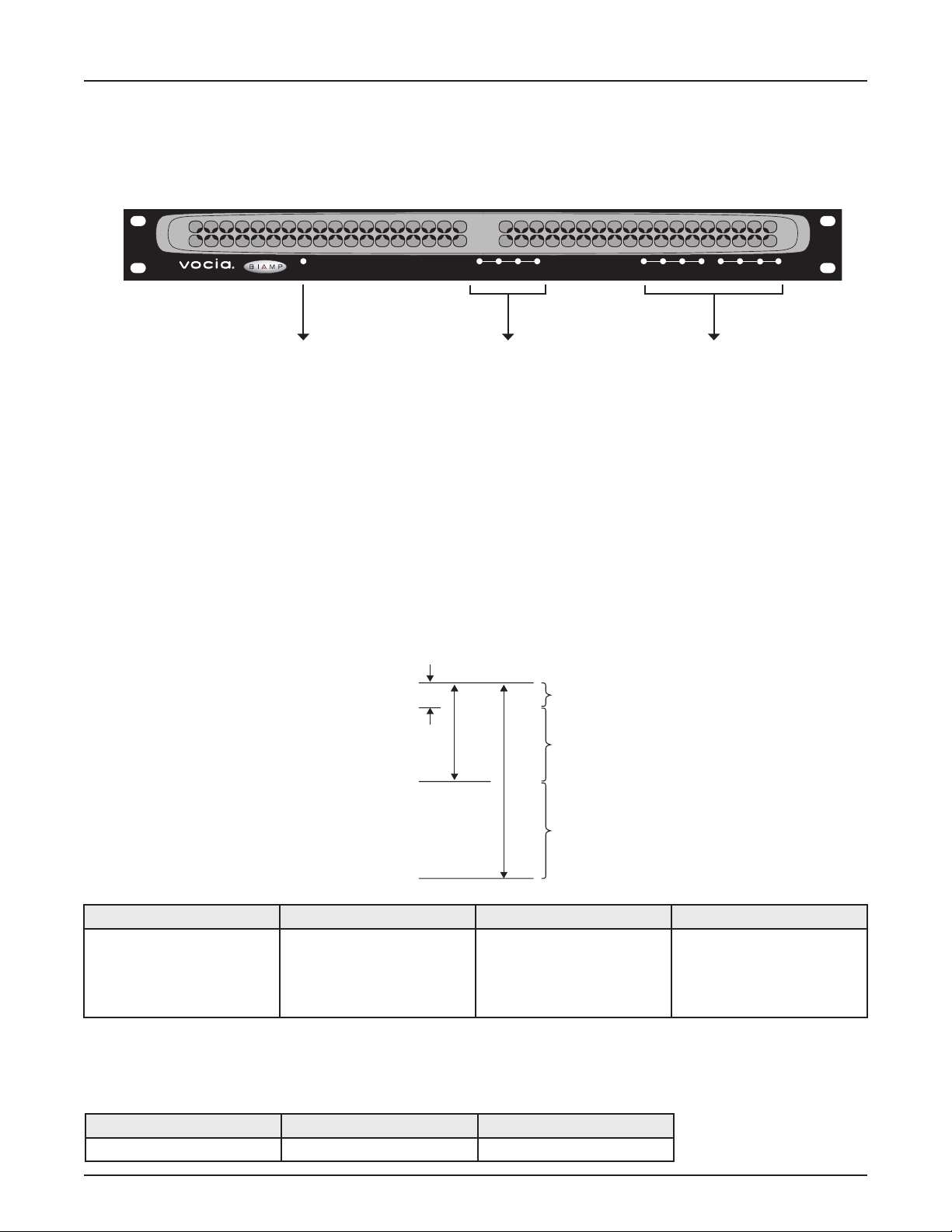
VO-4 FRONT PANEL
Power/
Network
Audio Ch annel Control Inpu tsControl Outpu ts
Output 4
1
2341234
1 234
Clip
-3
-18
-48
Red
Ye llow
Green
Nominal
Threshold
Setup and Use
The Vocia software provides an intuitive interface for conguration, DSP equalization, and programming of the VO-4. The information supplied
by this manual relates to physical connections and assignment. For more details on software setup, please consult the Vocia Help File.
1. Power Indicator LED 2. Signal LEDs 3. Control LEDs
1. Power Indicator LED
On the left of the front panel, the VO-4 has a single LED that indicates power and connectivity status:
1. Not illuminated: The device is not powered.
2. Flashing green: The unit is receiving power but not data, or the unit has not been congured correctly.
3. Solid green: The unit is operational, has been congured and is receiving PoE.
2. Signal LEDs
Four LEDs located in the center of the front panel act as audio signal identiers for the four input channels and are useful for setting optimum signal
levels. Each LED has four states. Please see the table below for the signal mapping to each of the LEDs. Detailed metering of current output levels
can be obtained in real time via the Vocia software interface.
Red Yellow Green Dark
Signal above clip threshold
> -3dBFS
3. Control LEDs
The control LEDs signal the current state of the control I/Os. The rst four are input status indicators, and the second four are output status indicators. They have three states:
Signal above nominal but below
clip threshold
> -18dBFS
< -3dBFS
Signal above minimum but
below nominal threshold
> -48dBFS
< -18dBFS
Signal below minimum threshold
< -48dBFS
Yellow Green Dark
Relays are energized > input threshold Not active
4
Page 5

Model VO-4
BIAMP SYSTEMS
Designed in Australia
Assembled in USA
YEL:in use/conductor
GRN:link/act
CobraNet
®
PoE IEEE 802.3af
Class 0
Device ID
MSB LSB
C NC NO C NC NO C NC NO C NC NO
1 2 3 4
Control Outputs
Control Inputs
Audio Outputs
1 2 3 4 10V
N24138
(100mA)
1
+
-
2
+
-
3
+
-
4
+
-
GND
Device ID
VO-4 REAR PANEL CONTROLS
Network
Connection
Control
Outputs
Control
Inputs
Audio Outputs
Network Connection
The VO-4 has one RJ45 connector that should be wired to standard copper Ethernet cabling to interface the VO-4 to a Vocia system via a
PoE-compliant network switch. The RJ45 connector has two LEDs that indicate Ethernet link and network activity (see table below).
Left LED Right LED Description
None None No power or data connectivity. Please check the PoE network connection.
None Green Link established.
Flashing
Green Link established and CobraNet activity detected; the unit is acting as a CobraNet performer.
yellow
Flashing
yellow
Flashing
Flashing
Link established and CobraNet activity detected; the unit is operating as a CobraNet conductor.
green
None CobraNet fault. Check cabling and conguration for errors.
yellow
Device ID
The rotary ID switches are located on the back of the VO-4 and give the unit a unique Device ID. The switches are in hexadecimal
format. All VO-4 units must have a unique Device ID to function properly within a Vocia Paging World (i.e., it is not possible to have
two VO-4 units with the same Device ID of hex 07). To assign a Device ID of hex 07, turn the LSB switch to 7 and leave the MSB
switch on 0. To create an ID of hex B7, turn the LSB switch to 7 and turn the MSB switch to B. Device ID switches should be set using
a 0.1 inch (2.5mm) to 0.12 inch (3.0mm) flat blade screwdriver. More information on setting IDs and the hexadecimal numbering
scheme used in Vocia can be found in the Vocia Help File.
Please note: Changes made to the Device ID while connected to the network require a power cycle in order to take effect.
CobraNet
The VO-4 is a CobraNet device. All CobraNet routing and bundle assignments are processed by the Vocia devices locally. Vocia makes
dynamic use of available bundles in CobraNet. Vocia devices are currently not interoperable with non-Vocia devices.
5
Page 6

VO-4 REAR PANEL CONTROLS
Ethernet switch
with PoE
VO-4
VO-4
Model VO-4
BIAMP SYSTEMS
Designed in Australia
Assembled in USA
YEL:in use/conductor
GRN:link/act
CobraNet
®
PoE IEEE 802.3af
Class 0
Device ID
MSB LSB
C NC NO C NC NO C NC NO C NC NO
1 2 3 4
Control Outputs
Control Inputs
Audio Outputs
1 2 3 4 10V
N24138
(100mA)
1
+
-
2
+
-
3
+
-
4
+
-
GND
Ethernet switch
without PoE
Model VO-4
BIAMP SYSTEMS
Designed in Australia
Assembled in USA
YEL:in use/conductor
GRN:link/act
CobraNet
®
PoE IEEE 802.3af
Class 0
Device ID
MSB LSB
C NC NO C NC NO C NC NO C NC NO
1 2 3 4
Control Outputs
Control Inputs
Audio Outputs
1 2 3 4 10V
N24138
(100mA)
1
+
-
2
+
-
3
+
-
4
+
-
GND
AC Power
PoE
injector
This connection carries control data, power, and digital audio over CobraNet. The maximum distance between any unit and an Ethernet
switch is 328 feet (100 meters) when using copper cabling. Additional Ethernet switches and/or ber-optic cable can be used to further
extend distances between units on a network. Please note that CobraNet limits network extensions to seven hops (one-way transmissions)
within a network.
If other network trafc shares an Ethernet switch with the Vocia network, a managed switch should be used with separate VLANs.
All Ethernet wiring is to be done using shielded CAT5, CAT5e, CAT6, or CAT7 cable.
6
Page 7

VO-4 REAR PANEL CONTROLS
Control Outputs
The Control Outputs, labeled 1 through 4, are isolated, voltage-free, software-congurable relay outputs.
The individual pins are labeled as follows:
1. (C): the common/ground pin
2. (NC): normally closed (connected to C when relay is not energized)
3. (NO): normally open (connected to C when relay is energized)
Control Inputs
The Control Inputs are labeled as follows:
1. ( ): logic common/ground input pin
2. (1–4): individual logic inputs
3. (10V): 10V reference voltage (when used as a switch input, a switch must be connected
between the input and logic common terminal)
Audio Inputs
Four plug-in barrier strip connectors provide analog audio signal output. The Vocia software enables a nominal output level of +4 dBu, 0 dBu,
or -10 dBu to support a wide range of connection devices. All plug-in barrier strip connectors should be wired from left to right as follows:
1. (+) High
2. (–) Low
3. ( ) Ground
Ground Screw
This screw provides a connection point to ground the chassis of the VO-4. The power supply to the VO-4 is sourced from PoE, which may
have no connection to ground. The chassis of the VO-4 should be connected to a safety ground (main power supply ground) using the
Ground Screw
7
Page 8

VO-4 INSTALLATION
Installation
The VO-4 requires one 1.75 inches (44.45mm) high and 19 inches (483mm) wide rack space with 10 inches (254mm) depth. Mounting the
unit using four screws with washers will prevent marring of the front panel. PVC or nylon washers are appropriate.
Please install the unit away from heat sources, such as vents and radiators, and in rooms with adequate ventilation. Ensure that air can
circulate freely behind, beside, and above the unit. Do not exceed the maximum ambient operating temperature of 113 degrees F (45°C).
Be aware of conditions in an enclosed rack that may cause the temperature to exceed ambient room conditions.
585.2046.90A
8
Page 9

Vocia Output 4 SPECIFICATIONS
Analog
Inputs
ID
Switches
Control
Outputs
Control
Inputs
LEDs
HostProcessor
Gain
CobraNet
audio and
control
D/A PoE
CobraNet
Processor
Frequency Response:
THD + N (20Hz to 8kHz):
Dynamic Range:
Crosstalk (10kHz):
20Hz to 20kHz + or – 1dB
VO-4 SPECIFICATIONS
Control Outputs
Type:
<0.02%
>80dB
>80dB
Max Operating Voltage:
Max Switching Capacity:
Min Operating Load:
Connection:
Power:
free change over contact
Form C Voltage
125VAC, 60VDC
37VA
10µA @ 10mV DC
RJ45 with shielded Ethernet/PoE cable
(CAT 5, CAT 5e, CAT6, or CAT 7)
802.3af (PoE) Class 3
Minimum Load Impedance:
Maximum Output Level:
Nominal Output Level:
A/D Converters:
Control Inputs
Type:
Max Input Threshold:
Max Input Voltage:
Min Input Threshold:
Input Impedance:
Vocia Output 4 BLOCK DIAGRAM
600kΩ
>+22dBu
-10dBu, 0dBu, or +4dBu
24-bit (48kHz sampling)
Digital, variable thresh-
old
10V
12V
150mV
100kΩ
Dimensions:
Height:
Width:
Depth:
Weight:
Ambient Operating
Temperature Range:
Compliance:
0.75 inches (44.5mm)
19 inches (483mm)
10 inches (254mm)
6.4 lbs. (2.9kg)
32-113 degrees F (0-45 degrees C)
EU Directive 2002/95/EC, RoHS directive
CE marked
9
Page 10

VO-4 WARRANTY
BIAMP SYSTEMS IS PLEASED TO EXTEND THE FOLLOWING 5-YEAR LIMITED WARRANTY TO THE ORIGINAL PURCHASER OF
THE PROFESSIONAL SOUND EQUIPMENT DESCRIBED IN THIS MANUAL
1. BIAMP Systems warrants to the original purchaser of new products that the product will be free from defects in material and
workmanship for a period of 5 YEARS from the date of purchase from an authorized BIAMP Systems dealer, subject to the
terms and conditions set forth below.
2 If you notify BIAMP during the warranty period that a BIAMP Systems product fails to comply with the warranty, BIAMP Systems
will repair or replace, at BIAMP Systems’ option, the nonconforming product. As a condition to receiving the benets of this warranty,
you must provide BIAMP Systems with documentation that establishes that you were the original purchaser of the products. Such
evidence may consist of your sales receipt from an authorized BIAMP Systems dealer. Transportation and insurance charges to
and from the BIAMP Systems factory for warranty service shall be your responsibility.
3. This warranty will be VOID if the serial number has been removed or defaced; or if the product has been altered, subjected to
damage, abuse or rental usage, repaired by any person not authorized by BIAMP Systems to make repairs; or installed in any
manner that does not comply with BIAMP Systems’ recommendations.
4. Electro-mechanical fans, electrolytic capacitors, gooseneck microphones, cords connecting handheld microphones, hard-drives,
displays, and normal wear and tear of items such as paint, knobs, handles, keypads and covers are not covered under this warranty. All server-based devices are warranted for 3 years only.
5. This warranty is in lieu of all other warranties, expressed or implied. BIAMP Systems disclaims all other warranties, expressed or
implied, including, but not limited to, implied warranties of merchantability and tness for a particular purpose.
6. The remedies set forth herein shall be the purchaser’s sole and exclusive remedies with respect to any defective product.
7. No agent, employee, distributor or dealer of BIAMP Systems is authorized to modify this warranty or to make additional warranties on behalf of BIAMP Systems. Statements, representations or warranties made by any dealer do not constitute warranties by
BIAMP Systems. BIAMP Systems shall not be responsible or liable for any statement, representation or warranty made by any
dealer or other person.
8. No action for breach of this warranty may be commenced more than one year after the expiration of this warranty.
9. BIAMP Systems shall not be liable for special, indirect, incidental, or consequential damages, including lost prots or loss of use
arising out of the purchase, sale, or use of the products, even if BIAMP Systems was advised of the possibility of such damages.
10
Page 11

COMPLIANCE
11
Page 12

COMPLIANCE
12
 Loading...