

Page 1

®
Vocia
DS-4/DS-10
Operation Manual
Biamp Systems, 9300 S.W. Gemini Drive, Beaverton, Oregon 97008 U.S.A. (503) 641-7287 www.biamp.com
Page 2

TABLE OF CONTENTS
VOCIA DESK STATION 4/10 (DS-4/DS-10) FEATURES . . . . . . . . . . . . . . . . . . . . . . . . . . . . . . . . . . . . . 3
TOP VIEW ..........................................................................................4
Setup and Use . . . . . . . . . . . . . . . . . . . . . . . . . . . . . . . . . . . . . . . . . . . . . . . . . . . . . . . . . . . . . . . . . . . . . . . . . . . . . . . . . . . . . 4
Display . . . . . . . . . . . . . . . . . . . . . . . . . . . . . . . . . . . . . . . . . . . . . . . . . . . . . . . . . . . . . . . . . . . . . . . . . . . . . . . . . . . . . . . . . . . 4
Microphone . . . . . . . . . . . . . . . . . . . . . . . . . . . . . . . . . . . . . . . . . . . . . . . . . . . . . . . . . . . . . . . . . . . . . . . . . . . . . . . . . . . . . . . 4
Soft Key Buttons ...................................................................................4
Destination Buttons . . . . . . . . . . . . . . . . . . . . . . . . . . . . . . . . . . . . . . . . . . . . . . . . . . . . . . . . . . . . . . . . . . . . . . . . . . . . . . . . 4
Push-to-Talk Button . . . . . . . . . . . . . . . . . . . . . . . . . . . . . . . . . . . . . . . . . . . . . . . . . . . . . . . . . . . . . . . . . . . . . . . . . . . . . . . . 4
BOTTOM VIEW ..................................................................................5-6
Device ID . . . . . . . . . . . . . . . . . . . . . . . . . . . . . . . . . . . . . . . . . . . . . . . . . . . . . . . . . . . . . . . . . . . . . . . . . . . . . . . . . . . . . . . . . 5
CobraNet . . . . . . . . . . . . . . . . . . . . . . . . . . . . . . . . . . . . . . . . . . . . . . . . . . . . . . . . . . . . . . . . . . . . . . . . . . . . . . . . . . . . . . . . . 5
Network Connection . . . . . . . . . . . . . . . . . . . . . . . . . . . . . . . . . . . . . . . . . . . . . . . . . . . . . . . . . . . . . . . . . . . . . . . . . . . . . . . . 5
Personal Identication Number (PIN) Security ...........................................................6
DISPLAY . . . . . . . . . . . . . . . . . . . . . . . . . . . . . . . . . . . . . . . . . . . . . . . . . . . . . . . . . . . . . . . . . . . . . . . . . . . . . . . . . . . . . . . . . . . 7
Display Status Messages . . . . . . . . . . . . . . . . . . . . . . . . . . . . . . . . . . . . . . . . . . . . . . . . . . . . . . . . . . . . . . . . . . . . . . . . . . . . 7
Device Information . . . . . . . . . . . . . . . . . . . . . . . . . . . . . . . . . . . . . . . . . . . . . . . . . . . . . . . . . . . . . . . . . . . . . . . . . . . . . . . . . 7
SPECIFICATIONS & BLOCK DIAGRAM .......................................................8
WARRANTY . . . . . . . . . . . . . . . . . . . . . . . . . . . . . . . . . . . . . . . . . . . . . . . . . . . . . . . . . . . . . . . . . . . . . . . . . . . . . . . . . . . . . . . 9
2
Page 3
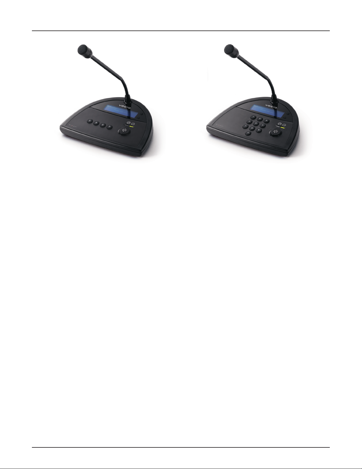
VOCIA DESK STATION 4/10 (DS-4/DS-10)
DS-4 DS-10
The Vocia® Desk Stations 4/10 (DS-4/DS-10) are digital networked paging devices. Both the DS-4 and the DS-10 feature embedded DSP
processing and on-board memory to support standard and advanced public address and mass notication functionalities. The DS-4 can
store four user-congurable Page Codes; and the DS-10 can store 999 user-congurable Page Codes. Additionally, all device-specic
conguration information is stored locally, which means the Desk Stations do not rely on a centralized controller for processing and page
routing. Thus, the processing, routing and storage functionality in a Vocia system is decentralized and spread across multiple networked
devices. This eliminates the single point of failure and builds redundancy directly into the network. As part of the Vocia network, the DS-4
and DS-10 are a perfect t for paging requirements in facilities of all sizes.
Features
Push-to-Talk button with status indication •
Four user-congurable Page Codes (DS-4)•
Up to 999 user-congurable Page Codes (DS-10)•
Four priority levels•
Local digital signal processing, including gain, lters, and compressor/limiter•
Local storage of conguration data•
Local storage of default and/or custom preambles•
Built-in store and forward functionality •
CobraNet•
®
audio/control, plus power on single cable.
Backlit liquid crystal display (LCD) technology•
Optional PIN to restrict unauthorized use•
High-quality gooseneck cardioid microphone•
Sturdy component housing•
Rotary ID switches for unit identication•
CE• marked and RoHS compliant
Covered by • BIAMP Systems’ warranty
3
Page 4
DS-4/DS-10 TOP VIEW
Setup and Use
The Vocia software provides an intuitive interface for conguration, DSP equalization and programming of the DS-4 and DS-10 compnents.
The information supplied by this manual relates to physical connections and assignment. For more details on software setup, please consult
the Vocia Help File.
Display
Both the DS-4 and the DS-10 features a backlit display that provides the user with an easy-to-read interface to view paging information.
Microphone
The DS-4 and the DS-10 microphone has a cardioid polar pattern. Correct operation of the microphone is essential for good speech
intelligibility. The recommended distance between the user’s mouth and the microphone is between 2 and 4 inches (50 and 100mm).
Closer use may cause distortion and unwanted bass boost, while more distant use may result in inadequate sound level.
Soft Key Buttons
Two soft key buttons are located to the right of the display. In the default state they are used as “Next” and “Previous” buttons to browse
through the Page Codes assigned to either the DS-4 or the DS-10. If PIN security is enabled (see PIN Security section of this document for
more information), the soft key buttons are used to “Clear” or “Enter” PIN entries. During a delayed page, the soft key buttons are used
to cancel the delayed page if required.
Destination Buttons
On the DS-4 there are four buttons located below the display which enables the user to select from one fo four predetermned Page Codes.
On the DS-10, the ten-digit keypad located below the display enables the user to select from one of 999 predetermined Page Codes. The
destination buttons are set up using the Vocia software. For stations that are PIN-enabled (see PIN Security section of this document for
more information), these buttons are also used for PIN entry.
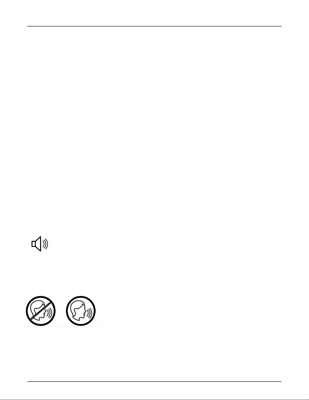
Push-to-Talk Button
The Push-to-Talk (PTT) button, represented by the speaker icon, triggers the action associated with the selected Page Code
(generally a live page, delayed page or recorded message).
Status LEDs
The status LEDs are located directly above the PTT button and inform the user of the current state of the paging station once the PTT
button is pressed. The left amber LED “Wait” indicator illuminates while the system establishes audio paths, checks for zone availability,
and plays the chime (if selected). The right green LED “Please Talk Now” indicator illuminates once the DS-4 or DS-10 audio path is live.
4
Page 5

DS-4/DS-10 BOTTOM VIEW
Device ID
The rotary ID switches are located on the bottom of the DS-4 and DS-10 and give the unit a unique Device ID. The switches are in
hexadecimal format. All desk station units must have a unique Device ID to function within a Vocia Paging World (i.e., it is not possible
to have two desk station units with the same Device ID of hex 07). To assign a Device ID of hex 07, turn the LSB switch to 7 and leave the
MSB switch on 0. To create an ID of hex B7, turn the LSB switch to 7 and turn the MSB switch to B. Device ID switches should be set
using a 0.1 inch (2.5mm) to 0.12 inch (3.0mm) at blade screwdriver. More information on setting IDs and the hexadecimal numbering
scheme used in Vocia can be found in the Vocia Help File.
Please note: Changes made to the Device ID while connected to the network require a power cycle in order to take effect.
CobraNet
Both the DS-4 and DS-10 are CobraNet devices. All CobraNet routing and bundle assignments are processed by the Vocia devices locally.
Vocia devices are not interoperable with non-Vocia devices.
Network Connection
The DS-4 and DS-10 have two RJ45 connectors located on the bottom of the unit that are labeled (1) Audio Network and (2) Option. The
Audio Network connector should be wired to shielded CAT5, CAT5e, CAT6 or CAT7 cable cabling to interface the DS-4 or DS-10 to
a Vocia system via a PoE-compliant network switch. The Option connector is currently not used. The RJ45 connector provides two LEDs
that indicate Ethernet link and network activity (see table below).
Left LED Right LED Description
None None No power or data connectivity. Please check the PoE network connection.
Green None Link established.
Green Flashing
amber
Flashing
green
Flashing
amber
Flashing
amber
Flashing
amber
Link established and CobraNet activity detected; the unit is acting as a CobraNet performer.
Link established and CobraNet activity detected; the unit is operating as a CobraNet conductor.
CobraNet fault. Check cabling and conguration for errors.
5
Page 6

DS-4/DS-10 BOTTOM VIEW
DS-4/DS-10
Ethernet switch
with PoE
DS-4/DS-10
Ethernet switch
without PoE
AC Power
PoE
injector
This connection carries control data, power and digital audio over CobraNet. PoE-enabled network switches or PoE midspan adapters
must be used to power the DS-10. These must be 802.3af compliant and must be isolated with respect to ground. The maximum distance
between any unit and an Ethernet switch is 328 feet (100 meters) when using copper cabling. Additional Ethernet switches and/or ber-optic
cable can be used to further extend distances between units on a network. Please note that CobraNet limits network extensions to seven
hops (one-way transmissions) within a network.
If other network trafc shares an Ethernet switch with the Vocia network, a managed switch should be used with separate VLANs.
The following diagrams illustrate valid network connections for either the DS-4 or the DS-10.
Personal Identication Number (PIN) Security
Both the DS-4 and DS-10 can be congured for PIN security protection. See the sections below for directions based on a specic model.
DS-4: If PIN security is enabled via the Vocia software, the four Page Code buttons may be used to enter the required four-digit PIN (see
button labeling examples below). To enter a number, the user may need to press a button multiple times (as in SMS messaging). During PIN
entry, the two “Next” and “Previous” soft key buttons on the right side of the display act as a “Clear” and an “Enter” key respectively. Input the
four-digit PIN sequentially, followed by the “Enter” key or the PTT button. Each digit will be shown briey on the display and subsequently
replaced by an asterisk for security purposes. If the entered PIN is correct, the station will unlock and be ready for use. To lock the wall
station on the initial set up, enter the PIN and push both the “Clear” and “Enter” button simultaneously.
Please note: PIN functionality is OPTIONAL.
It is turned OFF by default and must be set up
in the Vocia software.
DS-10: If PIN security is enabled via the Vocia software, the ten-digit keypad may be used to enter the required four-digit PIN. During PIN
entry, the two “Next” and “Previous” soft key buttons on the right side of the display act as a “Clear” and an “Enter” key respectively. Input the
four-digit PIN sequentially, followed by the “Enter” key or the PTT button. Each digit will be shown briey on the display and subsequently
replaced by an asterisk for security purposes. If the entered PIN is correct, the station will unlock and be ready for use.
After a period of inactivity (no pages made and no buttons pressed), both the DS-4 and DS-10 will revert back to a locked state. This length
of time (at a default of 180 seconds) is set using the Vocia software. To lock the station instantly, the user can press and hold down the “Next”
and “Previous” buttons at the same time.
6
Page 7

DS-4/DS-10 DISPLAY
Display Status Messages
The following messages are used to display the state of the DS-4 or DS-10 during normal operation. More information on display status
messages can be found in the Vocia Help File.
1. Destination Idle: This status message indicates that the paging station is ready and there are no busy zones among the destinations
selected by the Page Code.
2. No Network: This status message indicates that the DS-4 or DS-10 is not connected to a functioning network. Please check network
connections and settings.
3. Destination Busy: This status message signies that at least one of the destination zones is busy with a lower priority page.
When paging into a busy zone, the lower priority message will be lost.
4. Destination Delay: This status message indicates that at least one of the destination zones is busy with a page of equal priority.
When paging into a busy zone at an equal priority, the message will be recorded in the DS-4 or DS-10 locally and played when the
busy zones become available.
5. Not Available: This status message indicates that the selected Page Code is not available. The message “Code Barred” or “Undened”
will appear in the top left corner of the display. Please choose a different Page Code or assign the selected Page Code to the desk station.
6. Please Wait: This status message signies that the PTT button has been pressed and the system is assigning paging resources
and playing the chime. Simultaneously, the amber LED below the “Wait” icon will illuminate.
7. Request Failed: This indicates that the PTT button has been pressed and the request has failed. If a recorded message is associated
with this Page Code, please check that an MS-1 is online and congured to play the announcement.
8. Please Talk Now: This status message indicates that the PTT button has been pressed, the page has been correctly set up in the
system, any assigned chime has nished playing, and the audio path is open. This status message corresponds with the green
LED illuminated below the “Please Talk Now” icon.
9. Request Queued: This status message reports that the selected Page Code represents a request to play a recorded announce-
ment. When the zone(s) are ready to receive the announcement, the message will be played and the DS-4 or DS-10 will return to
the Destination Idle state.
10. Cancel Request?: This status message indicates that the selected Page Code is a Delayed Release page. Once the PTT button
is released, the “Cancel” prompt will ash on the display. The “Cancel Request?” message is displayed for ve seconds. If the user
presses the Cancel button within this ve-second period, the recorded page will be discarded and the system will return to idle
status. If ve seconds elapses and the user does not press the Cancel button, the message will be released for playback as soon as
all destination zones are available.
11. Page Will End in “x” Secs: This status message is displayed when a page termination is imminent (either due to lack of memory or
a timeout). The “x” signies a value in seconds.
Device Information
To access the device information, such as Device ID, the system time, and the time and date of the last rmware update, please press
and hold down any combination of three of the ten Page Code buttons.
Device ID System Time
Time/date of last
Firmware update
585.0252.90A
7
Page 8

DS-4/DS-10 SPECIFICATIONS
Te st Gen
Gain
CobraNet
audio and
control
A/D PoE
CobraNet
Processor
Keypad
LCD
ID Switches
Aux Port
Microphone
HostProcessor
Desk Station 4/10 SPECIFICATIONS
Frequency Response (electronics):
+0,-1dB, 100Hz to 20kHz
A/D Converters:
24-bit (48kHz sampling)
Effective Input Headroom:
Gain:
System Headroom:
Maximum Input:
THD + N (100Hz to 8kHz): <0.05%
Mic Type:
Mic Pattern:
Mic Frequency Response:
Adjustable in 1dB steps
over a 30dB range
125dB SPL
electret condenser
cardioid
100Hz-10kHz
Desk Station 4/10 BLOCK DIAGRAM
30dB
18dB
Connection:
Power:
Overall Dimensions
(excl. microphone):
Height:
Width:
Depth:
Mic Gooseneck Length:
Weight:
Ambient Operating
Temperature Range:
Compliance:
RJ45 with shielded Ethernet/PoE cable
(CAT5, CAT5e, CAT6 or CAT7)
802.3af (PoE) Class 2
2.1 inches (54mm)
9.5 inches (241mm)
7.4 inches (187mm)
12.5 inches (317.5mm)
Approx. 3.0 8lbs. (1.4kg)
32-113 degrees F (0-45 degrees C)
EU Directive 2002/95/EC, RoHS directive
CE marked
8
Page 9

DS-4/DS-10 WARRANTY
BIAMP SYSTEMS IS PLEASED TO EXTEND THE FOLLOWING 5-YEAR LIMITED WARRANTY TO THE ORIGINAL PURCHASER OF
THE PROFESSIONAL SOUND EQUIPMENT DESCRIBED IN THIS MANUAL
1. BIAMP Systems warrants to the original purchaser of new products that the product will be free from defects in material and
workmanship for a period of 5 YEARS from the date of purchase from an authorized BIAMP Systems dealer, subject to the
terms and conditions set forth below.
2 If you notify BIAMP during the warranty period that a BIAMP Systems product fails to comply with the warranty, BIAMP Systems will
repair or replace, at BIAMP Systems’ option, the nonconforming product. As a condition to receiving the benets of this warranty, you
must provide BIAMP Systems with documentation that establishes that you were the original purchaser of the products. Such
evidence may consist of your sales receipt from an authorized BIAMP Systems dealer. Transportation and insurance charges to and
from the BIAMP Systems factory for warranty service shall be your responsibility.
3. This warranty will be VOID if the serial number has been removed or defaced; or if the product has been altered, subjected to
damage, abuse or rental usage, repaired by any person not authorized by BIAMP Systems to make repairs; or installed in any
manner that does not comply with BIAMP Systems’ recommendations.
4. Electro-mechanical fans, electrolytic capacitors, gooseneck microphones, cords connecting handheld microphones, hard-drives,
displays, and normal wear and tear of items such as paint, knobs, handles, keypads and covers are not covered under this
warranty. All server-based devices are warranted for 3 years only.
5. This warranty is in lieu of all other warranties, expressed or implied. BIAMP Systems disclaims all other warranties, expressed
or implied, including, but not limited to, implied warranties of merchantability and tness for a particular purpose.
6. The remedies set forth herein shall be the purchaser’s sole and exclusive remedies with respect to any defective product.
7. No agent, employee, distributor or dealer of BIAMP Systems is authorized to modify this warranty or to make additional warranties
on behalf of BIAMP Systems. Statements, representations or warranties made by any dealer do not constitute warranties by
BIAMP Systems. BIAMP Systems shall not be responsible or liable for any statement, representation or warranty made by any
dealer or other person.
8. No action for breach of this warranty may be commenced more than one year after the expiration of this warranty.
9. BIAMP Systems shall not be liable for special, indirect, incidental, or consequential damages, including lost prots or loss of use
arising out of the purchase, sale, or use of the products, even if BIAMP Systems was advised of the possibility of such damages.
9
Page 10

COMPLIANCE
10
Page 11

COMPLIANCE
11
 Loading...