

Page 1

®
Vocia
ANC-1
Operation Manual
Biamp Systems, 10074 S.W. Arctic Drive, Beaverton, Oregon 97005 U.S.A. (503) 641-7287 www.biamp.com
Page 2

TABLE OF CONTENTS
VOCIA AMBIENT NOISE COMPENSATION 1 (ANC-1) FEATURES . . . . . . . . . . . . . . . . . . . . . . . 3
SETUP AND USE . . . . . . . . . . . . . . . . . . . . . . . . . . . . . . . . . . . . . . . . . . . . . . . . . . . . . . . . . . . . . . . . . . . . . . . . . . . . . . .4-5
Device ID . . . . . . . . . . . . . . . . . . . . . . . . . . . . . . . . . . . . . . . . . . . . . . . . . . . . . . . . . . . . . . . . . . . . . . . . . . . . . . . . . . . . . . . . . 4
CobraNet . . . . . . . . . . . . . . . . . . . . . . . . . . . . . . . . . . . . . . . . . . . . . . . . . . . . . . . . . . . . . . . . . . . . . . . . . . . . . . . . . . . . . . . . . 4
Network Connection . . . . . . . . . . . . . . . . . . . . . . . . . . . . . . . . . . . . . . . . . . . . . . . . . . . . . . . . . . . . . . . . . . . . . . . . . . . . . . . . 4
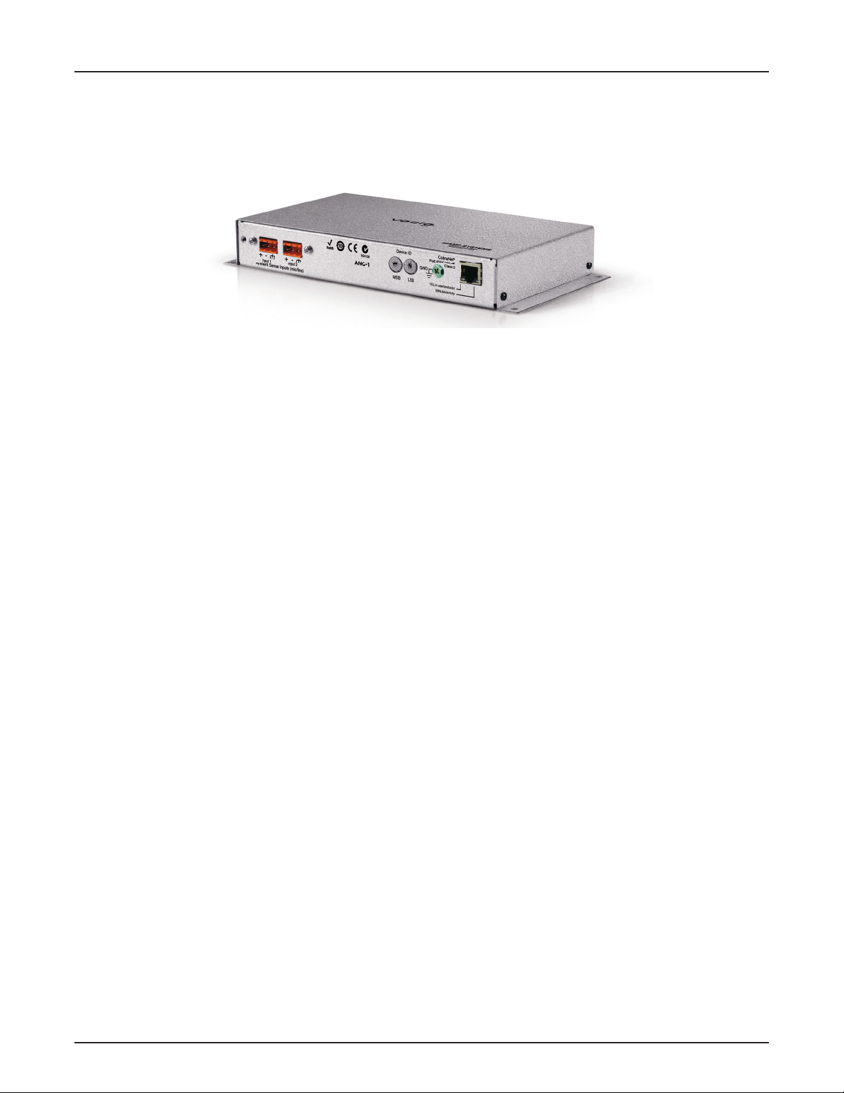
Ambient Noise Input Connections .....................................................................5
INSTALLATION ....................................................................................6
SPECIFICATIONS & BLOCK DIAGRAM .......................................................7
WARRANTY . . . . . . . . . . . . . . . . . . . . . . . . . . . . . . . . . . . . . . . . . . . . . . . . . . . . . . . . . . . . . . . . . . . . . . . . . . . . . . . . . . . . . . . 8
2
Page 3
VOCIA AMBIENT NOISE COMPENSATION 1 (ANC-1)
The ANC-1 allows the Vocia® system to adjust output levels automatically in response to changes in ambient noise levels. The ANC-1 is
a networked device for use with Biamp’s Vocia Amplier (VA-8600). It accepts two ambient noise inputs at microphone or line level. Most
high-quality dynamic and condenser microphones can be used in conjunction with the ANC-1. Input gain for each of the two inputs is user
congurable via the Vocia software interface. The ANC-1 processes the ambient noise information using Biamp’s adaptive ambient noise
compensation algorithm and sends data to the VA-8600 to change the output level accordingly. The Vocia software interface permits
comprehensive adjustment of ANC parameters. The ANC-1 utilizes IEEE compliant Power over Ethernet (PoE) technology.
FEATURES
Automatic, adaptive volume adjustment based on ambient noise sensing and processing•
48V phantom power•
Wall mountable•
CobraNet audio/control with dynamic use of available bundles, plus power over single Ethernet cable•
Status LEDs•
Sturdy component housing•
CE• marked and RoHS compliant
Covered by • BIAMP Systems’ warranty
3
Page 4

ANC-1 SETUP AND USE
Setup and Use
The Vocia software provides an intuitive interface for conguration of the ANC-1. The information supplied by this manual relates to physical
connections and assignment. For more details on setup of the ANC-1 operational parameters please consult the Vocia Help File.
Device ID
The rotary ID switches are located on the ANC-1 and give the unit a unique Device ID. The switches are in hexadecimal format. All
ANC-1 units must have a unique Device ID to function within a Vocia Paging World (i.e., it is not possible to have two ANC-1 units with
the same Device ID of hex 07). To assign a Device ID of hex 07, turn the LSB switch to 7 and leave the MSB switch on 0. To create
an ID of hex B7, turn the LSB switch to 7 and turn the MSB switch to B. Device ID switches should be set using a 0.1 inch (2.5mm)
to 0.12 inch (3.0mm) at blade screwdriver. More information on setting IDs and the hexadecimal numbering scheme used in Vocia
can be found in the Vocia Help File.
Please note: Changes made to the Device ID while connected to the network require a power cycle in order to take effect.
CobraNet
The ANC-1 is a CobraNet device. All CobraNet routing and bundle assignments are processed by the Vocia devices locally. Vocia makes
dynamic use of available bundles in CobraNet. Vocia devices are currently not interoperable with non-Vocia devices.
Network Connection
The ANC-1 has one RJ45 connector that should be wired to standard copper Ethernet cabling to interface the ANC-1 to a Vocia system via a
PoE-compliant network switch. The RJ45 connector two LEDs that indicate Ethernet link and network activity (see table below).
Left LED Right LED Description
None None No power or data connectivity. Please check the PoE network connection.
None Green Link established.
Flashing
yellow
Flashing
yellow
Flashing
yellow
This connection carries control data, power, and digital audio over a single Ethernet cable. PoE-enabled network switches or PoE
midspan adapters must be used to power the ANC-1. These must be 802.3af compliant. The maximum distance between any unit
and an Ethernet switch is 328 feet (100 meters) when using copper cabling. Additional Ethernet switches and/or ber-optic cable can
be used to further extend distances between units on a network. Please note that CobraNet limits network extensions to seven hops
(one-way transmissions) within a network.
Green Link established and CobraNet activity detected; the unit is acting as a CobraNet performer.
Flashing
green
None CobraNet fault. Check cabling and conguration for errors.
Link established and CobraNet activity detected; the unit is operating as a CobraNet conductor.
4
Page 5

ANC-1 SETUP AND USE
ANC-1
Ethernet switch
with PoE
ANC-1
Ethernet switch
without PoE
AC Power
PoE
injector
Device ID
LSBMSB
-+-
+
N24138
10
ANC-1
YEL:in use/conductor
CobraNet
®
PoE IEEE 802.3af
Class 2
GRN:link/activity
GND
Input 1 Input 2
Ambient Sense Inputs (mic/line)
Device ID
LSBMSB
-+-
+
N24138
10
ANC-1
YEL:in use/conductor
CobraNet
®
PoE IEEE 802.3af
Class 2
GRN:link/activity
GND
Input 1 Input 2
Ambient Sense Inputs (mic/line)
Ambient Noise Input Connections
Two plug-in barrier-strip connectors on the ANC-1 connect the ambient sensing sources to the device. One or two microphones or line-level
sources may be connected (gain adjusted accordingly in the Vocia software interface). Both connections may provide phantom power,
switchable from software (default: off). Multiple microphones may be mixed before connecting to the ANC-1.
5
Page 6

ANC-1 INSTALLATION
120mm, 4.724"
107.3mm, 4.224"
56.8mm, 2.235"
8.7mm, 0.343"
4.8mm, 0.34" dia.
9.5mm, 0.37" dia.
232.3mm, 9.146"
245mm, 9.64"
40mm, 1.575"
4.2mm, 0.166" dia., 4 places
Installation
The ANC-1 can be mounted on a wall using screws through the case anges (#6 or 6mm dia. X 4) or two screws in the keyholes on the
rear (#8 or 4.5mm dia., max 9mm dia. head).
Please install the unit away from heat sources, such as vents and radiators, and in rooms with adequate ventilation. Ensure that air can
circulate freely behind, beside, and above the unit. Do not exceed the maximum ambient operating temperature of 113 degrees F (45°C).
Be aware of conditions in an enclosed rack that may cause the temperature to exceed ambient room conditions.
585.0266.90A
6
Page 7

ANC-1 SPECIFICATIONS
PoE
CobraNet
Processor
CobraNet
Audio and Control
Pre-amp with
phantom power
Mic / line
input
A/D
Host
Processor
Ambient Noise Compensation 1 SPECIFICATIONS
Ambient Noise
Input Conguration: 2x balanced mic/line level
Phantom power: 48 VDC (7mA/
input) Compliant with IEC 1938
Plug-in barrier strip connectors
Input Impedance: 8k ohms (mic/line balanced) Metering: Ambient Level; Program Level;
Input gain range: 0dB – +66dB Power: 802.3af (PoE) Class 2
Environment RT60: 300mS to 2 Seconds
Compensation
Network Connection: RJ45 with shielded Ethernet/
PoE cable
(CAT 5, CAT 5e, CAT6, or CAT 7)
Compensation Range: +/- 25dB Weight: Approx 1.65 lbs (750 g)
Compensation Ratio: 0.25:1 to 4:1 Ambient Operating
Ramp In/Out Times: Minimum 1dB/Second;
Maximum 10dB/Second
Overall Dimensions
Height:
Width:
Depth:
Temperature Range: 32-113 degrees F (0-45 degrees C)
Compliance: EU Directive 2002/95/EC, RoHS directive
1.279 inches (32 mm)
9.646 inches (245 mm)
4.724 inches (120 mm)
CE marked
Ambient Noise Compensation 1 BLOCK DIAGRAM
7
Page 8

ANC-1 WARRANTY
BIAMP SYSTEMS IS PLEASED TO EXTEND THE FOLLOWING 5-YEAR LIMITED WARRANTY TO THE ORIGINAL PURCHASER OF
THE PROFESSIONAL SOUND EQUIPMENT DESCRIBED IN THIS MANUAL
1. BIAMP Systems warrants to the original purchaser of new products that the product will be free from defects in material and
workmanship for a period of 5 YEARS from the date of purchase from an authorized BIAMP Systems dealer, subject to the
terms and conditions set forth below.
2 If you notify BIAMP during the warranty period that a BIAMP Systems product fails to comply with the warranty, BIAMP Systems
will repair or replace, at BIAMP Systems’ option, the nonconforming product. As a condition to receiving the benets of this warranty,
you must provide BIAMP Systems with documentation that establishes that you were the original purchaser of the products. Such
evidence may consist of your sales receipt from an authorized BIAMP Systems dealer. Transportation and insurance charges to
and from the BIAMP Systems factory for warranty service shall be your responsibility.
3. This warranty will be VOID if the serial number has been removed or defaced; or if the product has been altered, subjected to
damage, abuse or rental usage, repaired by any person not authorized by BIAMP Systems to make repairs; or installed in any
manner that does not comply with BIAMP Systems’ recommendations.
4. Electro-mechanical fans, electrolytic capacitors, gooseneck microphones, cords connecting handheld microphones, hard-drives,
displays, and normal wear and tear of items such as paint, knobs, handles, keypads and covers are not covered under this warranty. All server-based devices are warranted for 3 years only.
5. This warranty is in lieu of all other warranties, expressed or implied. BIAMP Systems disclaims all other warranties, expressed or
implied, including, but not limited to, implied warranties of merchantability and tness for a particular purpose.
6. The remedies set forth herein shall be the purchaser’s sole and exclusive remedies with respect to any defective product.
7. No agent, employee, distributor or dealer of BIAMP Systems is authorized to modify this warranty or to make additional warranties on behalf of BIAMP Systems. Statements, representations or warranties made by any dealer do not constitute warranties by
BIAMP Systems. BIAMP Systems shall not be responsible or liable for any statement, representation or warranty made by any
dealer or other person.
8. No action for breach of this warranty may be commenced more than one year after the expiration of this warranty.
9. BIAMP Systems shall not be liable for special, indirect, incidental, or consequential damages, including lost prots or loss of use
arising out of the purchase, sale, or use of the products, even if BIAMP Systems was advised of the possibility of such damages.
8
Page 9

COMPLIANCE
9
Page 10

COMPLIANCE
10
 Loading...