

Page 1

®
Vocia
VO-4
Operation Manual
January 2012
Biamp Systems, 9300 SW Gemini Drive, Beaverton, Oregon 97008 U.S.A. (503) 641-7287 www.biamp.com
Page 2
IMPORTANT SAFETY INSTRUCTIONS
IMPORTANT SAFETY INSTRUCTIONS
1) Read these instructions.
2) Keep these instructions.
3) Heed all warnings.
4) Follow all instructions.
5) Do not use this product near water.
6) Clean only with dry cloth.
7) Do not block ventilation openings.
Install in accordance with the
manufacturer’s instructions.
8) Do not install near any heat
sources such as radiators, heat
registers, stoves, or other product
(including amplifiers) that produce
heat.
9) Do not defeat the safety purp
the grounding-type plug. A grounding
type plug has two blades and a third
grounding prong.
The third prong is provided for your
safety. If the provided plug does not
fit into your outlet, consult an
electrician for replacement of the
obsolete outlet.
ose of
10) Protect the power cord from being
walked on or pinched particularly at plugs,
convenience receptacles, and the point
where they exit from the product.
11) Only
speci
12) Use only with equipment rack, cart,
stand or table designed to provide adequate
mechanical strength, heat dissipation and
securement to the building structure.
When a cart is used, use
caution when moving the cart
and product combination to
avoid injury from tip-over.
13) Unplug this product during lightning
storms or when unused for long periods of
time.
14) Refer all servici
personnel.
product has been damaged in any way, such
as power-supply cord or plug is damaged,
liquid has been spilled or objects have fallen
into the product, the product has been
exposed to rain or moisture, does not
operate normally, or has been dropped.
use attachments/accessories
fied by the manufacturer.
ng to qualified service
Servicing is required when the
WARNING - To reduce the risk of fire or electric shock, do not expose this product to rain or
moisture.
WARNING - This product employs Safety Grounding and must be connected to a MAINS
socket that is properly grounded to provide a protective earthing connection.
Disconnect Device - The MAINS plug is used to disconnect MAINS power and must be
installed near the equipment and remain readily accessible.
Explanation of safety related symbols - Product labeling
use the internationally recognized symbols defined below to note safety messages.
Lightning Bolt: Hazardous Live voltages present when this unit is in operation. Do
not touch terminals marked with this symbol while the unit is connected to live power.
Exclamation Point: Replace components (i.e. fuses) only with the values specified by
the manufacturer. Failure to do so will compromise safe operation of this uni
and the operation manual may
t.
2
Page 3

TABLE OF CONTENTS
VOCIA OUTPUT 4 (VO-4) FEATURES .........................................................4
FRONT PANEL ....................................................................................5
Setup and Use .....................................................................................5
1. Power Indicator LED ..............................................................................5
2. Signal LEDs .....................................................................................5
3. Control LEDs ....................................................................................5
REAR PANEL CONTROLS ....................................................................6-8
Device ID .........................................................................................6
CobraNet .........................................................................................6
Network Connection ................................................................................6
Control Outputs ....................................................................................8
Control Inputs .....................................................................................8
Audio Inputs .......................................................................................8
Ground Screw .....................................................................................8
INSTALLATION ....................................................................................9
SPECIFICATIONS & BLOCK DIAGRAM ......................................................10
WARRANTY ......................................................................................11
FCC COMPLIANCE ..............................................................................12
EC DECLARATION ..............................................................................13
EU ROHS COMPLIANT .........................................................................14
3
Page 4
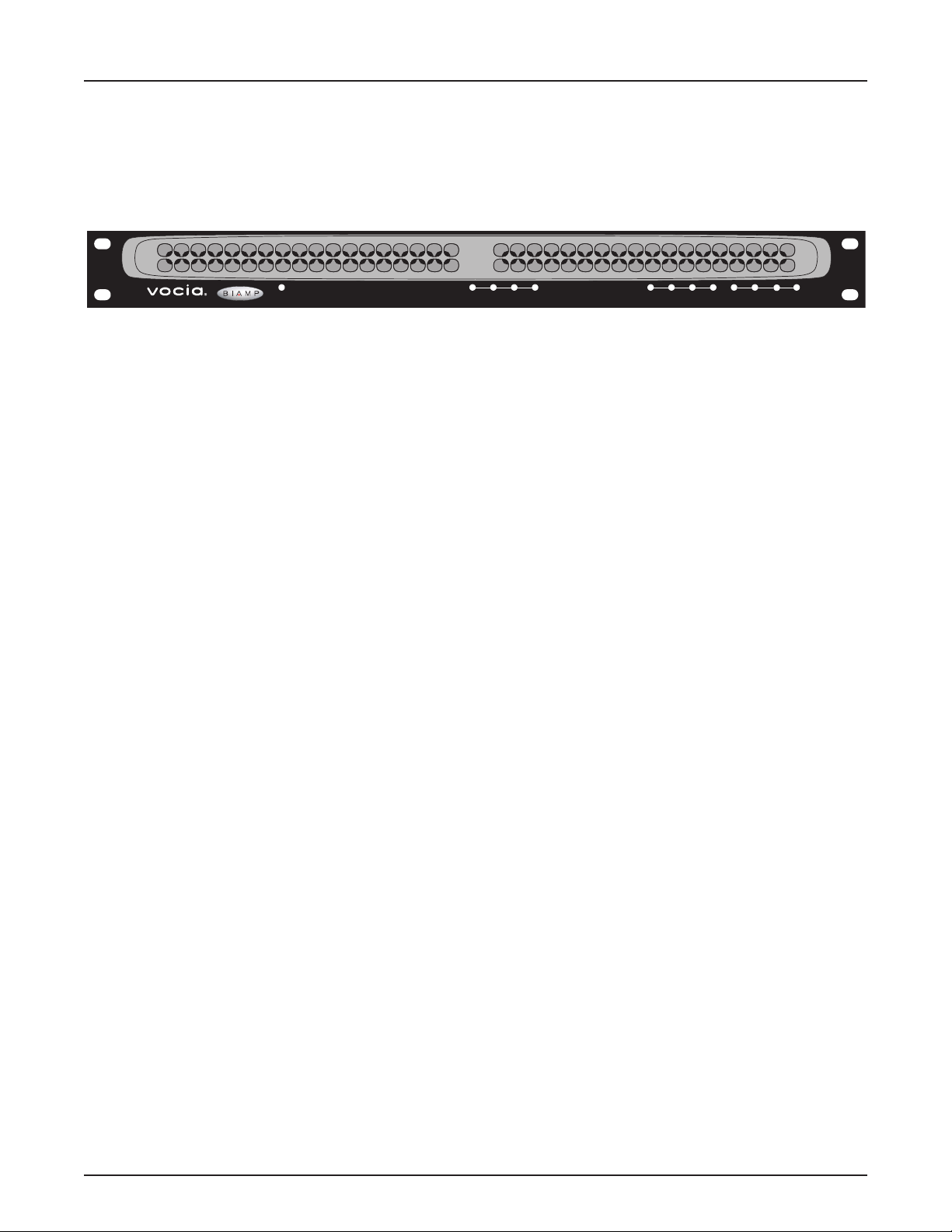
VOCIA OUTPUT 4 (VO-4)
Output 4
Power/
Network
1 234
Audio Channel Control InputsControl Outputs
The VO-4 is a networked audio output expansion device allowing the user to add four line-level output channels to a Vocia
1
2341234
®
system. The VO-4
accepts four channels of digital audio input via CobraNet® and provides four line-level analog audio outputs. The VO-4 features embedded
DSP and on-board memory to process and store all device-specic conguration information locally and includes comprehensive, xed-chain,
digital-signal processing. As part of the Vocia system, the VO-4 meets paging requirements for facilities of all sizes.
FEATURES
• Converts digital to analog
• Four removable terminal block connectors for line-level outputs
• Four control inputs and four control outputs
• Software-congurable local audio signal processing, including gain, lters, and compressor/limiter
• Rotary switches for unit identication
• Power Over Ethernet (PoE)
• CobraNet audio/control on single cable
• Status LEDs to indicate signal and clip
• CE marked and RoHS compliant
• Covered by BIAMP Systems’ warranty
4
Page 5
VO-4 FRONT PANEL
Setup and Use
The Vocia software provides an intuitive interface for conguration, DSP equalization, and programming of the VO-4. The information supplied
by this manual relates to physical connections and assignment. For more details on software setup, please consult the Vocia Help File.
Output 4
Power/
Network
1 234
Audio Channel Control InputsControl Outputs
1
2341234
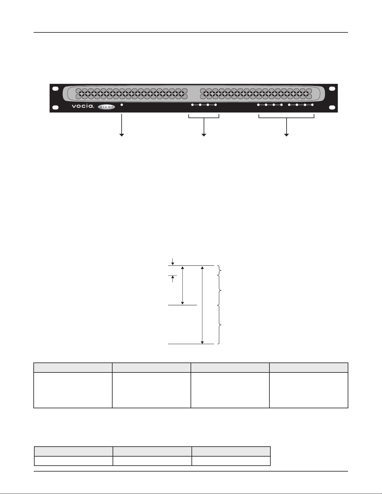
1. Power Indicator LED 2. Signal LEDs 3. Control LEDs
1. Power Indicator LED
On the left of the front panel, the VO-4 has a single LED that indicates power and connectivity status:
1. Not illuminated: The device is not powered.
2. Flashing green: The unit is receiving power but not data, or the unit has not been congured correctly.
3. Solid green: The unit is operational, has been congured and is receiving PoE.
2. Signal LEDs
Four LEDs located in the center of the front panel act as audio signal identiers for the four input channels and are useful for setting optimum signal
levels. Each LED has four states. Please see the table below for the signal mapping to each of the LEDs. Detailed metering of current output levels
Clip
-3
-18
Red
Yellow
Nominal
-48
Threshold
Green
Red Yellow Green Dark
Signal above clip threshold
> -3dBFS
Signal above nominal but below
clip threshold
> -18dBFS
< -3dBFS
Signal above minimum but
below nominal threshold
> -48dBFS
< -18dBFS
Signal below minimum threshold
< -48dBFS
can be obtained in real time via the Vocia software interface.
3. Control LEDs
The control LEDs signal the current state of the control I/Os. The rst four are input status indicators, and the second four are output status indicators. They have three states:
Yellow Green Dark
Relays are energized > input threshold Not active
5
Page 6

BIAMP SYSTEMS
Designed in Australia
Assembled in USA
GND
PoE IEEE 802.3af
Class 0
YEL:in use/conductor
GRN:link/act
®
CobraNet
Device ID
MSB LSB
Device ID
VO-4 REAR PANEL CONTROLS
N24138
Control Outputs
C NC NO C NC NO C NC NO C NC NO
1 2 3 4
Control Inputs
1 2 3 4 10V
(100mA)
Audio Outputs
-
-
-
+
+
1
2
-
+
+
3
4
Model VO-4
Network
Connection
Control
Outputs
Control
Inputs
Audio Outputs
Network Connection
The VO-4 has one RJ45 connector located on the rear panel that utilizes standard Ethernet cabling to interface the VO-4 to the Vocia system
via a managed network switch. The RJ45 connector provides two LEDs that indicate Ethernet link and network activity (see table below).
Left LED Right LED Description
None None No power or data connectivity. Please check the PoE network connection.
Green None Link established.
Green Flashing
Link established and CobraNet activity detected; the unit is acting as a CobraNet performer.
amber
Flashing
green
Flashing
amber
Flashing
amber
Flashing
amber
Link established and CobraNet activity detected; the unit is operating as a CobraNet conductor.
CobraNet fault. Check cabling and conguration for errors.
Device ID
The rotary ID switches are located on the back of the VO-4 and give the unit a unique Device ID. The switches are in hexadecimal
format. All VO-4 units must have a unique Device ID to function properly within a Vocia Paging World (i.e., it is not possible to have
two VO-4 units with the same Device ID of hex 07). To assign a Device ID of hex 07, turn the LSB switch to 7 and leave the MSB
switch on 0. To create an ID of hex B7, turn the LSB switch to 7 and turn the MSB switch to B. Device ID switches should be set using
a 0.1 inch (2.5mm) to 0.12 inch (3.0mm) flat blade screwdriver. More information on setting IDs and the hexadecimal numbering
scheme used in Vocia can be found in the Vocia Help File.
Please note: Changes made to the Device ID while connected to the network require a power cycle in order to take effect.
CobraNet
The VO-4 is a CobraNet device. All CobraNet routing and bundle assignments are processed by the Vocia devices locally. Vocia devices
are not interoperable with non-Vocia devices.
6
Page 7

VO-4 REAR PANEL CONTROLS
This connection carries control data, power, and digital audio over CobraNet. The maximum distance between any unit and an Ethernet
switch is 328 feet (100 meters) when using copper cabling. Additional Ethernet switches and/or ber-optic cable can be used to further
extend distances between units on a network. Please note that CobraNet limits network extensions to seven hops (one-way transmissions)
within a network.
If other network trafc shares an Ethernet switch with the Vocia network, a managed switch should be used with separate VLANs.
All Ethernet wiring is to be done using shielded CAT5, CAT5e, CAT6, or CAT7 cable.
VO-4
BIAMP SYSTEMS
GND
Designed in Australia
Assembled in USA
PoE IEEE 802.3af
Class 0
YEL:in use/conductor
GRN:link/act
®
CobraNet
Device ID
MSB LSB
N24138
Control Outputs
C NC NO C NC NO C NC NO C NC NO
1 2 3 4
Control Inputs
1 2 3 4 10V
(100mA)
Audio Outputs
-
-
-
+
+
1
2
-
+
+
3
4
Model VO-4
Ethernet switch
with PoE
VO-4
BIAMP SYSTEMS
Designed in Australia
Assembled in USA
GND
PoE IEEE 802.3af
Class 0
YEL:in use/conductor
GRN:link/act
®
CobraNet
Device ID
C NC NO C NC NO C NC NO C NC NO
MSB LSB
1 2 3 4
N24138
Control Outputs
Control Inputs
1 2 3 4 10V
(100mA)
-
+
1
PoE
injector
+
Audio Outputs
-
2
Model VO-4
-
-
+
+
3
4
Ethernet switch
without PoE
AC Power
7
Page 8

VO-4 REAR PANEL CONTROLS
Control Outputs
The Control Outputs, labeled 1 through 4, are isolated, voltage-free, software-congurable relay outputs.
The individual pins are labeled as follows:
1. (C): the common/ground pin
2. (NC): normally closed (connected to C when relay is not energized)
3. (NO): normally open (connected to C when relay is energized)
Control Inputs
The Control Inputs are labeled as follows:
1. ( ): logic common/ground input pin
2. (1–4): individual logic inputs
3. (10V): 10V reference voltage (when used as a switch input, a switch must be connected
between the input and logic common terminal)
Audio Inputs
Four plug-in barrier strip connectors provide analog audio signal output. The Vocia software enables a nominal output level of +4 dBu, 0 dBu,
or -10 dBu to support a wide range of connection devices. All plug-in barrier strip connectors should be wired from left to right as follows:
1. (+) High
2. (–) Low
3. ( ) Ground
Ground Screw
This screw provides a connection point to ground the chassis of the VO-4. The power supply to the VO-4 is sourced from PoE, which may
have no connection to ground. The chassis of the VO-4 should be connected to a safety ground (main power supply ground) using the
Ground Screw
8
Page 9

VO-4 INSTALLATION
Installation
The VO-4 requires one 1.75 inches (44.45mm) high and 19 inches wide rack space with 10 inches (254mm) depth. Mounting the unit using
four screws with washers will prevent marring of the front panel. PVC or nylon washers are appropriate.
Please install the unit away from heat sources, such as vents and radiators, and in rooms with adequate ventilation. Ensure that air can
circulate freely behind, beside, and above the unit. Do not exceed the maximum ambient operating temperature of 113 degrees F (45°C).
Be aware of conditions in an enclosed rack that may cause the temperature to exceed ambient room conditions.
9
Page 10

VO-4 SPECIFICATIONS
Vocia Output 4 SPECIFICATIONS
Frequency Response:
THD + N (20Hz to 8kHz): <0.02%
Dynamic Range:
Crosstalk (10kHz):
20Hz to 20kHz + or – 1dB
>80dB
>80dB
Control Outputs
Type:
Max Operating Voltage:
Max Switching Capacity:
Min Operating Load:
Connection:
Power:
Form C Voltage
free change over contact
125VAC, 60VDC
37VA
10µA @ 10mV DC
RJ45 with shielded Ethernet/PoE
cable (CAT5, CAT5e, CAT6 or CAT7)
802.3af (PoE) Class 3
Minimum Load Impedance:
Maximum Output Level:
Nominal Output Level:
A/D Converters:
Control Inputs:
Type:
Max Input Threshold:
Max Input Voltage:
Min Input Threshold:
Input Impedance:
Vocia Output 4 BLOCK DIAGRAM
Analog
Inputs
Switches
-10dBu, 0dBu, or +4dBu
24-bit (48kHz sampling)
Digital, variable threshold
LEDs
ID
600kΩ
>+22dBu
150mV
100kΩ
Dimensions:
Height:
Width:
Depth:
Weight:
Ambient Operating
Temperature Range:
Compliance:
10V
12V
HostProcessor
0.75 inches (44.5mm)
19 inches (483mm)
10 inches (254mm)
6.4 lbs. (2.9kg)
32-113 degrees F (0-45 degrees C)
FCC Part 15, class B
CE marked
RoHS Directive
UL 60065 Listed, E215636
C-UL Listed, E215636
C-Tick, N24138 (Australia)
Control
Inputs
Control
Outputs
Gain
D/A PoE
CobraNet
Processor
10
CobraNet
audio and
control
Page 11

VO-4 WARRANTY
BIAMP SYSTEMS IS PLEASED TO EXTEND THE FOLLOWING 5-YEAR LIMITED WARRANTY TO THE ORIGINAL PURCHASER OF
THE PROFESSIONAL SOUND EQUIPMENT DESCRIBED IN THIS MANUAL
1. BIAMP Systems warrants to the original purchaser of new products that the product will be free from defects in material and
workmanship for a period of 5 YEARS from the date of purchase from an authorized BIAMP Systems dealer, subject to the
terms and conditions set forth below.
2 If you notify BIAMP during the warranty period that a BIAMP Systems product fails to comply with the warranty, BIAMP Systems
will repair or replace, at BIAMP Systems’ option, the nonconforming product. As a condition to receiving the benets of this warranty,
you must provide BIAMP Systems with documentation that establishes that you were the original purchaser of the products. Such
evidence may consist of your sales receipt from an authorized BIAMP Systems dealer. Transportation and insurance charges to
and from the BIAMP Systems factory for warranty service shall be your responsibility.
3. This warranty will be VOID if the serial number has been removed or defaced; or if the product has been altered, subjected to
damage, abuse or rental usage, repaired by any person not authorized by BIAMP Systems to make repairs; or installed in any
manner that does not comply with BIAMP Systems’ recommendations.
4. Electro-mechanical fans, electrolytic capacitors, gooseneck microphones, cords connecting handheld microphones, hard-drives,
displays, and normal wear and tear of items such as paint, knobs, handles, keypads and covers are not covered under this warranty. All server-based devices are warranted for 3 years only.
5. This warranty is in lieu of all other warranties, expressed or implied. Biamp Systems disclaims all other warranties, expressed or
implied, including, but not limited to, implied warranties of merchantability and tness for a particular purpose.
6. The remedies set forth herein shall be the purchaser’s sole and exclusive remedies with respect to any defective product.
7. No agent, employee, distributor or dealer of Biamp Systems is authorized to modify this warranty or to make additional warranties
on behalf of Biamp Systems. Statements, representations or warranties made by any dealer do not constitute warranties by Biamp
Systems. Biamp Systems shall not be responsible or liable for any statement, representation or warranty made by any dealer or
other person.
8. No action for breach of this warranty may be commenced more than one year after the expiration of this warranty.
9. Biamp systems shall not be liable for special, indirect, incidental, or consequential damages, including lost prots or loss of use
arising out of the purchase, sale, or use of the products, even if BIAMP Systems was advised of the possibility of such damages.
012012_585.0246.90B
11
Page 12

FCC COMPLIANCE
FCC NOTICE - CLASS B DIGITAL DEVICE
NOTE: This equipment has been tested and found to comply with the limits for a Class B digital device,
pursuant to Part 15 of the FCC Rules. These limits are designed to provide reasonable protection against
harmful interference in a residential as well as in a commercial installation. This equipment generates, uses and
can radiate radio frequency energy and, if not installed and used in accordance with the instructions, may cause
harmful interference to radio communications. However, there is no guarantee that interference will not occur in a
particular installation. If this equipment does cause harmful interference to radio or television reception, which can
be determined by turning the equipment off and on, the user is encouraged to try to correct the interference by
one or more of the following measures: 1) Reorient or relocate the receiving antenna, 2) Increase the separation
between the equipment and receiver, 3) Connect the equipment into an outlet on a circuit different from that to
which the receiver is connected or 4) Consult the dealer or an experienced radio/TV technician for help.
12
Page 13

COMPLIANCE
DoC VO201003!
EC Declaration of Conformity
Biamp Systems Corporation, as manufacturer having sole responsibility, hereby
declares that the following described product complies with the applicable provisions of
the DIRECTIVES below except as noted herein. Any alterations to the product not
agreed upon and directed by Biamp Systems Corporation will invalidate this declaration.
Product Model
Product Description
Applicable EC Directives
LVD Directive (2006/95/EC) Safety EN 60065:2002
EMC Directive (2004/108/EC) Emissions EN 55103-1:1996, Environment E2
Immunity EN 55103-2:1996
Special Considerations for Product Environment or Compliance
Use only CE marked Power over Ethernet (PoE) device.
Use only CE and “LPS” marked 24 VDC External Power Adaptor.
Shielded cabling must be used for system connections.
Technical Construction File, Location and Contact
Biamp Systems Corporation phone: (503) 641.7287
9300 S.W. Gemini Drive fax: (503) 626.0281
Beaverton, OR USA 97008 e-mail: compliance@biamp.com
Authorized Representative: Larry Copley, Compliance Engineer
: Vocia® VO-4
: Output Expander for networking with audio DSPs
: Applicable Harmonized Standards:
:
:
Authorized Signature:
Issued: March 2010
13
Page 14

COMPLIANCE
EU RoHS COMPLIANT
This Biamp product, including all attendant cables and accessories
supplied by Biamp, meets all requirements of EU Directives
2002/95/EC of January 27, 2003, and 2005/618/EC of August 18,
2005, the EU RoHS Directives. An EU RoHS Materials Content
Declaration document may be obtained at www.biamp.com
(The following information is presented to comply with the requirements of Chinese law SJ/T11363-2006)
有害物质表 (Hazardous Substances Table)
Biamp Systems Corporation
音频输出设备 (Audio Output Device)
Vocia VO-4
质或元
Pb 铅Hg汞Cd 镉Cr+6
部件名称
设备机箱(EquipmentChassis)
插拔式接线端子 (Plug-in Terminal Blocks)
光盘(CD ROM)
手册和其他书面文档 (Manual and Documentation)
包装箱和所有包装材料 (Box and Packing Materials)
X O X O O O
O O O O O O
O O O O O O
O O O O O O
O O O O O O
六价铬
PBB PBDE
0:表示该部件所有均质材料中的这种有毒有害物质低于 SJ/T11363-2006 的限制要求.
X:表示该部件中至少有一种均质材料所含的这种有毒有害物质高于 SJ/T11363-2006 的限制要求.
在电触头和(或)镀镉所含的均质材料中,镉及其化合物的含量可以超过 0.01%,但欧盟指令 91/338/EEC(根据欧盟指令
76/769/EEC)限制销售和使用某些危险物质和制剂部分中所禁止的用途除外
在以下一种或多种物质所含的均质材料中,铅及其化合物的含量可以超过 0.1%:
1) 电子元器件中玻璃内所含的铅
2) 铅在钢材中是作为一种合金元素,含量可达 0.35%
3) 铅在铝材中是作为一种合金元素,含量可达 0.4%
4) 铅在铜材中是作为一种合金元素,含量可达 4%
5) 高熔点类焊料中的铅(即铅料合金,铅含量超过 85%)
6) 电子陶瓷部件内的铅
7) 由两种以上元素组成的焊料中所含的铅,用于连接针脚和微处理器包装,其中
铅的含量超过 80% 但低于 85%
8) 顺应针连接系统内的铅
9) 导载体之间形成连焊料中
在正常使用情况下,中国环保使用期限为 10 年,条件是:
• 环境温度为 0-40C (32-104°F)
• 湿度为 0-95%,无凝结
• 海拔高度为 0-10,000 英尺
• 气流不受阻碍
• 没有水或其他液体进入任何部件
• 电源为 IEEE 802.3af PoE
• 部件没有损坏(损坏部件应立即修理)
•
14
 Loading...