

Page 1

SPM723
Programmable
Stereo Preamp/Mixer
Operation Manual
Biamp Systems, 10074 S.W. Arctic Drive, Beaverton, Oregon 97005 U.S.A. (503) 641-7287 www.biamp.com
an affiliate of Rauland-Borg Corp.
Page 2

print update
September 7, 2005
Page 3

TABLE OF CONTENTS
Front & Rear Panel Features
Setup
Logic Inputs
Logic Outputs
RS-232 Control
Specifications & Block Diagram
Warranty
pgs. 2 & 3
pgs. 4~13
pg. 14
pg. 15
pgs. 16 & 17
pg. 18
SPM723
INTRODUCTION
The SPM723 provides seven stereo line inputs, two mono mic/line inputs, and
three stereo outputs. Complete programmability and control of the SPM723
includes independent left/right levels for each input and output, mic/line routing
& priority, automatic/manual program ducking, mic/line & output tone
adjustment, and 16 memory presets. The SPM723 is extremely versatile, with
software customized setup, making it ideally suited for many applications
including meeting rooms, restaurant/bars, and retail stores.
SPM723 features include:
♦ settings programmed via BiampWin PC control software
♦ seven stereo line inputs, with individual volume & mute
♦ ‘surround sound’ support assigns input 6 to the aux output
♦ input 7 assignable stereo unbalanced or mono balanced
♦ input 7 'override' select via external switch or input signal
♦ two balanced mic/line inputs, with HPF & phantom power
♦ mic/line inputs include individual trim, tone, volume & mute
♦ stereo input ‘ducking’ via external switch or mic/line signals
♦ separate left/right or stereo ‘ganged’ faders on all inputs
♦ independent stereo main & stereo zone balanced outputs
♦ balanced stereo aux output, with independent source select
♦ outputs include 3-band, mid-sweep stereo tone adjustment
♦ outputs independently assignable for stereo/mono operation
♦ separate left/right or stereo ‘ganged’ faders on all outputs
♦ signal level meters on input 7, mic/line inputs, & all outputs
♦ mixing of multiple input signals or selection of single source
♦ store & recall up to sixteen non-volatile memory presets
♦ remote control via RS-232 & programmable logic inputs
®
♦ Windows
95/98/NT/2000/XP software & cable included
♦ incorporates AES recommended grounding practices
marked and UL / C-UL listed power source
♦
♦ covered by Biamp Systems' five year warranty
1
Page 4

FRONT & REAR PANEL FEATURES
FRONT PANEL FEATURES
Activity LED: This red LED indicates when control information is
being received via RS-232.
On Indicator: When the power transformer is plugged in, and AC
power is applied to the SPM723, the red On indicator remains lit.
When power is removed, all 'current' settings (sources, levels,
tone, etc.) will be stored in non-volatile memory and recalled when
power is restored. During Setup the SPM723 may instead be set
to always recall Preset #1 when power is turned back on (see
Setup on pg. 10).
SPM723
onactivity
REAR PANEL FEATURES
AC Power Cord: The power transformer provides 27 Volts AC to
the SPM723, and is detachable via a 5-pin DIN connector. The
SPM723 has two internal ‘self-resetting’ fuses (there are no user
serviceable parts inside the unit). If the internal fuses blow, they
will attempt to re-set after a short period. However, this may be an
indication that the SPM723 requires service.
Serial Port: This 9-pin Sub-D (male) connector provides an RS232 Serial Port for remote control via computer or third-party
controllers (see RS-232 Control on pg. 16). The Serial Port has
the following pin assignments (left-to-right & top-to-bottom): Pin 1)
not used; Pin 2) Receive Data (RxD) input; Pin 3) Transmit
Data (TxD) output; Pin 4) Data Terminal Ready (DTR) output;
Pin 5) Ground; Pin 6) not used; Pin 7) Request To Send (RTS)
output; Pin 8) not used; Pin 9) not used. BiampWin software
and a null-modem cable are provided for programming (see Setup
on pg. 4). NOTE: The Serial Port can also transmit commands
received via the Logic Inputs (see Setup on pg. 9).
Link Port: This 9-pin Sub-D (female) connector provides a Link
Port for RS-232 control of multiple BIAMP products (see RS-232
Control on pg. 16). The Link Port of one device simply connects to
the Serial Port of the next device (and so forth). Link cables are
available as an option (Biamp #909-0057-00). NOTE: All but the
final device in a system should have the Link Switch pressed in
(see below). The Link Port has the following pin assignments
(right-to-left & top-to-bottom): Pin 1) not used; Pin 2) Transmit
Data (TxD) output; Pin 3) Receive Data (RxD) input; Pin 4) not
used; Pin 5) Ground; Pin 6) not used; Pin 7) not used; Pin 8)
not used; Pin 9) not used. NOTE: The Link Port will also
transmit commands received via the Logic Inputs (see Setup on
pg. 9).
Link Switch: The Link Switch is used when connecting multiple
devices in a ‘Link Port to Serial Port’ configuration (see Link Port
above). From the factory, the Link Switch is released (out). When
connecting multiple devices, the Link Switch must be depressed
(in) on all devices except
the final device in the system (the device
with no Link Port connection).
2
Page 5

FRONT & REAR PANEL FEATURES
RL L R
zone output main output
27V
~
50/60 Hz
27 watts
class 2 wiring
SPM
723
serial port
link port link
logic outputs
logic inputs
Logic Outputs: This 9-pin Sub-D connector provides Logic
Outputs 1~8 (see Logic Outputs on pg. 15). Logic Outputs may
be used to control external switching circuits, such as relays or
other BIAMP products. These outputs are typically used to
provide simultaneous audio & video source selection, by
controlling an external video switching device.
Logic Inputs: This 9-pin Sub-D (female) connector provides
eight logic inputs for controlling the SPM723 via contactclosures (see Logic Inputs on pg. 14). Logic Input functions are
programmed via software (see Setup on pg. 9). NOTE: From
the factory, Logic Inputs 1~8 have no pre-programmed function.
Main & Zone Outputs: These plug-in barrier strips provide the
balanced stereo line-level Main & Zone Outputs. For balanced
output, wire high to (+), low to (-), and ground to (
unbalanced output (-6dB gain), wire high to (+) and ground to
d
(
), leaving (-) unconnected. Main & Zone Outputs can be set
for stereo or mono operation, and include signals from Line
Inputs 1~7 and Mic/Line Inputs 1 & 2, as determined via
software (see Setup on pg. 4).
Aux Output: This plug-in barrier strip provides the balanced
stereo line-level Aux Output. For balanced output, wire high to
(+), low to (-), and ground to (
gain), wire high to (+) and ground to (
d
). For unbalanced output (-6dB
d
), leaving (-)
unconnected. Aux Output can be set for stereo or mono
operation, and includes signals from Main & Zone Outputs, as
determined via software (see Setup on pg. 7).
d
). For
L R
aux output
override
sig pres
L R
line
inputs
L
R
L
R
L
R
mute
sig pres
mute
sig pres
1234567override
mic/line 2
mic/line 1mute mute
Line Inputs 1~6: These RCA connectors provide the
unbalanced stereo Line Inputs 1~6.
Line Input 7: This plug-in barrier strip provides the unbalanced
stereo Line Input 7. Line Input 7 can instead be set for balanced
mono input, via software (see Setup on pg. 4).
Override: This plug-in barrier strip provides Line Input 7
Override, which is a priority selection of that input over all other
stereo line inputs. Wiring (sig pres) to (override) causes
automatic override whenever signal is present at Line Input 7.
Manual override instead uses a contact-closure wired between
(override) & (
d
). Override functions are determined via
software (see Setup on pg. 13).
Mic/Line Inputs 1 & 2: These plug-in barrier strips provide the
balanced mono inputs for Mic/Line 1 & 2. For balanced input,
wire high to (+), low to (-), and ground to (
input, wire high to (+), and ground to both (-) & (
d
). For unbalanced
d
). Mic/Line 1
& 2 functions are determined via software (see Setup on pg. 6).
Mute: These plug-in barrier strips provide for ‘talk-over' ducking
of the stereo line input signals. By wiring (signal present) to
(mute), automatic ducking will occur whenever signal is present
at the respective Mic/Line Input. Manual ducking instead uses a
contact-closure wired between (mute) & (
d
). Mute functions are
determined via software (see Setup on pgs. 11 & 12).
3
Page 6
SETUP
SPM723 parameters are all adjustable using the BiampWin software and null-modem cable provided with the unit. The BiampWin software
provides programs for various BIAMP products, including the SPM723. The SPM723 program includes seven
described on the following pages. Once the software is started (and Comm Port Configuration is set), the control screens are accessed via
the drop-down menus at the top of the opening screen. The Mix
Main Program
Definitions, Logic Input Definitions, & Configuration Options. The File menu provides functions such as save, open, download, etc. The
Settings
available adjustments. To install BiampWin Software
System Requirements
, Zone Program, Mic/Line 1 / Mic/Line 2, & Aux Output. The Configure SPM723 menu offers additional screens for Button
menu recalls the Comm Port Configuration screen. The Window menu arranges active product screens. The Help menu explains
: Select ‘Run’ from ‘Start’ menu, and browse to 'BiampWin' on appropriate drive.
: Windows® 95/98/NT/2000/XP with 8MB of available hard disk space (serial port required for ‘on-line’ operation).
screen appears whenever an SPM723 file is opened, and it has four tabs:
control screens, which are
MAIN PROGRAM SCREEN
The Main Program
on each input can be assigned for separate left/right or stereo ganged operation. Line Input 7 includes a signal level meter, and can be
assigned as either a normal unbalanced stereo line input or as a special balanced mono line input. The Main Output section also provides
faders which can be assigned for separate left/right or stereo ganged operation, and includes a mute button, a 3-band mid-sweep EQ, and
a signal level meter. In addition, the Main Output may be switched from stereo operation to mono operation (a mono sum of the left/right
signals then appears at both outputs). The bottom of the screen shows on/off status of the eight Logic Inputs and the eight Logic Outputs.
Sixteen buttons are provided for recalling non-volatile memory presets. A separate Store button provides a menu for storing settings into
the sixteen memory preset locations. Presets contain settings affecting all inputs/outputs. The title bar at the top of the Mix screen shows
Device #, custom Device Name, & model of product being controlled. BiampWin software can operate ‘off-line’ (no product connected) by
opening a ‘new’ file for the desired product. The Device # for ‘off-line’ files is assigned sequentially as a negative number.
tab on the Mix screen provides level faders & mute buttons for mixing Line Inputs 1~7 to the Main Output. The faders
4
Page 7
SETUP
ZONE PROGRAM SCREEN
The Zone Program
on each input can be assigned for separate left/right or stereo ganged operation. Line Input 7 includes a signal level meter, and can be
assigned as either a normal unbalanced stereo line input or as a special balanced mono line input. The Zone Output section also provides
faders which can be assigned for separate left/right or stereo ganged operation, and includes a mute button, a 3-band mid-sweep EQ, and
a signal level meter. In addition, the Zone Output may be switched from stereo operation to mono operation (a mono sum of the left/right
signals then appears at both outputs). The bottom of the screen shows on/off status of the eight Logic Inputs and the eight Logic Outputs.
Sixteen buttons are provided for recalling non-volatile memory presets. A separate Store button provides a menu for storing settings into
the sixteen memory preset locations. Presets contain settings affecting all inputs/outputs. The title bar at the top of the Mix screen shows
Device #, custom Device Name, & model of product being controlled. BiampWin software can operate ‘off-line’ (no product connected) by
opening a ‘new’ file for the desired product. The Device # for ‘off-line’ files is assigned sequentially as a negative number.
tab on the Mix screen provides level faders & mute buttons for mixing Line Inputs 1~7 to the Zone Output. The faders
5
Page 8
SETUP
MIC/LINE 1 / MIC/LINE 2 SCREEN
The Mic/Line 1 / Mic/Line 2
Zone Outputs. The faders on each input can be assigned for separate left/right or stereo ganged operation. Each Mic/Line Input includes
adjustable Gain, with a Peak indicator and a signal level meter. Gain adjusts the input to compensate for different signal levels. For best
performance, adjust Gain so the Peak indicator flashes on occasional peaks in signal level (8dB before clipping). Each Mic/Line Input also
includes selection boxes for Enable, High Pass Filter, & Phantom Power. Enable Main allows that Mic/Line Input signal to be available for
mixing to the Main Output. Enable Zone allows that Mic/Line Input signal to be available for mixing to the Zone Output. NOTE: Enable
Main & Enable Zone also affect the ability for the associated Mic/Line input to initiate ‘ducking’ (see Miscellaneous Screen on pg. 10). High
Pass Filter reduces the Mic/Line Input low frequency signals 6dB/octave @ 110Hz. Phantom Power turns on +24 Volt at the Mic/Line
Input, for powering condenser mics. EQ provides Bass & Treble equalization (tone control) for each Mic/Line Input. Main Mic Priority
selects which Mic/Line Input (if any) shall have priority over the other Mic/Line Input, at the Main Output. Zone Mic Priority selects which
Mic/Line Input (if any) shall have priority over the other Mic/Line Input, at the Zone Output. NOTE: Mic/Line Input signals are mixed to the
outputs ‘post-fader’. Therefore, Main/Zone Output EQ and fader settings do NOT
The bottom of the screen shows on/off status of the eight Logic Inputs and the eight Logic Outputs. Sixteen buttons are provided for
recalling non-volatile memory presets. A separate Store button provides a menu for storing settings into the sixteen memory preset
locations. Presets contain settings affecting all inputs/outputs. The title bar at the top of the Mix screen shows Device #, custom Device
Name, & model of product being controlled. BiampWin software can operate ‘off-line’ (no product connected) by opening a ‘new’ file for the
desired product. The Device # for ‘off-line’ files is assigned sequentially as a negative number.
tab on the Mix screen provides level faders & mute buttons for mixing Mic/Line Inputs 1 & 2 to both the Main &
affect Mic/Line Input signals which appear at the outputs.
6
Page 9

SETUP
AUX OUTPUT SCREEN
The Aux Output
tab on the Mix screen provides faders which can be assigned for separate left/right or stereo ganged operation, and
includes a mute button, a 3-band mid-sweep EQ, and a signal level meter. In addition, the Aux Output may be switched from stereo
operation to mono operation (a mono sum of the left/right signals then appears at both outputs). Unlike the Main/Zone Outputs, the Aux
Output does not allow input signals to be mixed directly to it. Instead, the Aux Output only allows Source Selection of input signals, as they
appear at the Main and/or Zone Outputs. NOTE: Mic/Line Input signals are mixed to the Aux Output ‘pre-fader’. Therefore, Aux Output
EQ & fader settings, as well as Mic/Line EQ & fader settings, BOTH
exception to this Source Selection routine is Input 6 (Surround)
affect Mic/Line Input signals which appear at the Aux Output. One
, which allows Input 6 to be mixed directly to the Aux Output for surround
sound applications. Under these circumstances, the Input 6 faders on the Main Program screen are used instead to feed Input 6
exclusively to the Aux Output (not to the Main or Zone Outputs). The Input 6 faders on the Zone Program screen become disabled. With
appropriate signals applied to Input 6, the Aux Output can then be used to provided the additional 5
th
& 6th (center & sub) outputs necessary
for surround sound. Other inputs receive the signals representing Front L & R and Rear L & R, which would then be mixed to the Main &
Zone Outputs (see Applications on pg. 21). NOTE: To select Input 6 (Surround), it must first be enabled via the Miscellaneous Screen
(see Miscellaneous Screen on pg. 10). The bottom of the screen shows on/off status of the eight Logic Inputs and the eight Logic Outputs.
Sixteen buttons are provided for recalling non-volatile memory presets. A separate Store button provides a menu for storing settings into
the sixteen memory preset locations. Presets contain settings affecting all inputs/outputs. The title bar at the top of the Mix screen shows
Device #, custom Device Name, & model of product being controlled. BiampWin software can operate ‘off-line’ (no product connected) by
opening a ‘new’ file for the desired product. The Device # for ‘off-line’ files is assigned sequentially as a negative number.
7
Page 10
SETUP
BUTTON DEFINITION SCREEN
The Button Definitions
buttons. Although the SPM723 does not accept commands from push-button remote controls directly, it can receive individual ASCII
characters (via RS-232) from other BIAMP products or third-party control systems.
equivalent ASCII characters permanently assigned to them (see RS-232 Control on pg. 16). Therefore, a Remote Control Button can be
assigned specific ‘actions’, which the SPM723 will then perform whenever the equivalent ASCII character for that button is received. From
the factory, Remote Control Buttons have no pre-programmed functions. However, using the Button Definitions screen, each Remote
Control Button may be assigned various ‘actions’. Remote Control Buttons
Character displays the permanent ASCII character for the selected button. Store Preset allows store actions for Presets 1~16 to be
assigned to the selected button. Recall Preset
allows ‘on’, ‘off’, & ‘toggle’ actions for Logic Outputs 1~8 to be assigned to the selected button. Echo Character
character for the selected button. NOTE: Echo Characters are permanent for Remote Control Buttons, and can only be changed for Logic
Inputs (see next page). Main Volume & Zone Volume
Output, & Zone Output to be assigned to the selected button. Aux Volume
assigned to the selected button. Clear
additional instruction. Try It
the Button Definitions screen.
screen is accessed through the Configue SPM723 menu, and is used to assign specific ‘actions’ to remote control
allows recall actions for Presets 1~16 to be assigned to the selected button. Logic Outputs
allow specific volume & muting actions for Line Inputs 1~7, Mic/Line 1 & 2, Main
allows specific volume & muting actions for Aux Output to be
allows all actions assigned to the selected button (or all buttons) to be cleared. Help provides
causes the actions currently assigned to the selected button to be performed by the SPM723. Close will close
From the factory, Remote Control Buttons have
selects which button is to be defined. Equivalent ASCII
displays the ‘echo’
8
Page 11
SETUP
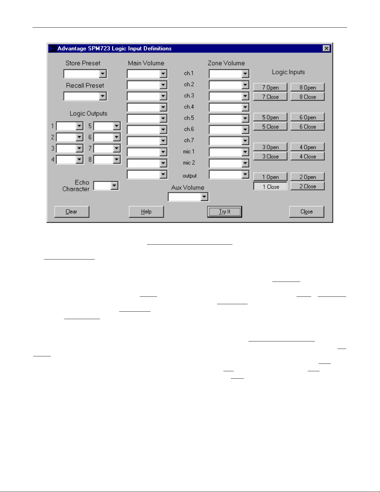
LOGIC INPUT DEFINITION SCREEN
The Logic Input Definitions
Inputs. Logic Inputs allow remote control of the SPM723 via external circuits, such as switches, contact-closures, active driver circuits,
and/or ‘open-collector’ logic outputs (see Logic Inputs on pg. 14). From the factory, Logic Inputs 1~8 have no pre-programmed functions.
However, using the Logic Input Definitions screen, each Logic Input may be assigned various ‘actions’. Logic Inputs
Input is to be defined. NOTE: Since Logic Inputs are controlled by switches, contact-closures, etc., each Logic Input may be assigned
certain actions to perform when the switch is ‘opened
allows store actions for Presets 1~16 to be assigned to the selected Logic Input. Recall Preset
assigned to the selected Logic Input. Logic Outputs
Logic Input. Echo Character
character which will be transmitted via the Serial Port/Link Port whenever that Logic Input is switched. From the factory, no echo
characters are assigned to Logic Inputs 1~8. Changing the Echo Character is used primarily for customizing remote control commands
amongst various RS-232 controlled products within a system (see RS-232 Control on pg. 16). Main Volume & Zone Volume
volume & muting actions for Line Inputs 1~7, Mic/Line 1 & 2, Main Output, & Zone Output to be assigned to the selected button. Aux
Volume allows specific volume & muting actions for Aux Output to be assigned to the selected button. NOTE: Although Logic Input
volume actions include a ‘repeating’ (volume ramp) function, they will not continuously repeat the echo character via RS-232. Clear
all actions assigned to the selected Logic Input (or all Logic Inputs) to be cleared. Help
actions currently assigned to the selected Logic Input to be performed by the SPM723. Close
screen is accessed through the Configure SPM723 menu, and is used to assign specific ‘actions’ to the Logic
’, and different actions to perform when that same switch is ‘closed’. Store Preset
allows ‘on’, ‘off’, & ‘toggle’ actions for Logic Outputs 1~8 to be assigned to the selected
allows the ‘echo’ character for the selected Logic Input to be changed. NOTE: This is the RS-232 ASCII
selects which Logic
allows recall actions for Presets 1~16 to be
provides additional instruction. Try It causes the
will close the Logic Input Definitions screen.
allow specific
allows
9
Page 12

SETUP
MISCELLANEOUS SCREEN
The Configuration Options screen is accessed through the Configure SPM723 menu, and the Miscellaneous
Options screen is then used to select options which customize the operation of the SPM723. At the top of the Miscellaneous screen, the
Serial Number
product connected) by opening a ‘new’ file for the desired product. The Serial Number & Firmware Version are not displayed for ‘new’ (offline) files. Device Name
be stored in the SPM723 memory, and will be displayed on the title bar of the Mix screen whenever that SPM723 is accessed using the
software. Device Number
control of multiple units. Surround Sound Support
provide the additional independent outputs necessary for surround sound applications (see Aux Screen on pg. 7) Power-Up Status
determines what settings the SPM723 will automatically recall whenever power is turned on. From the factory, the SPM723 is set to recall
the settings which existed prior to power being shut off. Recall Preset 1 at Power Up
preset at power-up. Main Program Page-Over Ducking
applied to stereo Line Input 1~7 signals, and how quickly they return to normal level, when ducking has been triggered (see Mute on pg. 3).
Duck Amount
choices (1dB~200dB per second). NOTE: A Mic/Line Input must be enabled to an output before it can trigger ducking at that output (see
Mic/Line Screen on pg. 6). Restore Defaults
to be set back to their factory defaults. Help
and Firmware Version of the particular SPM723 will be displayed. The BiampWin software can operate ‘off-line’ (with no
allows a custom name to be given to the SPM723, by entering up to 30 characters of text. The Device Name will
opens a drop-down menu which allows assignment of an ‘address’ number (0~63) to the SPM723, for computer
enables Input 6 source selection on the Aux screen, which allows the Aux Output to
and Zone Program Page-Over Ducking determine the amount of attenuation
opens a drop-down menu of 41 attenuation choices (0dB~80dB). Ramp Rate opens a drop-down menu of 200 return rate
opens a pop-up menu, which allows the Miscellaneous options (or all Configuration Options)
provides additional instruction. Close will return you to the Mix screen.
tab on the Configuration
will instead cause the SPM723 to recall this specific
10
Page 13

SETUP
MUTE 1 / MIC 1 SCREEN
The Configuration Options screen is accessed through the Configure SPM723 menu, and the Mute 1 / Mic 1
Options screen is then used to select options which customize the function of the Mic/Line 1 Mute terminal (see Front & Rear Panel
Features on pg. 3). Mute 1 Input Causes Gated Operation of Mic 1
that mic/line input signal to remain off, until triggered on either manually (via contact-closure) or automatically (via signal present) at the
Mute 1 terminal. Mute 1 Input Causes Page-Over Duck of the Main Program Source
Mute 1 Input Causes Page-Over Duck of the Zone Program Source
temporary attenuation of the stereo Line Input 1~7 signals at that output, which is triggered manually (via contact-closure) or
(via signal present) at the Mute 1 terminal. NOTE: A Mic/Line Input must be enabled before it can trigger ducking (see Mic/Line Screen on
pg. 6). Mute 1 Hold Time
mute functions remain in effect after
determines how fast a signal returns to normal after
the Mute 1 functions described above, and instead allow the Mute 1 terminal to be used as a logic input, which can then be programmed
like a remote control button (see Setup on pg. 8). However, a logic input can have two
‘closed’ (activated) and another for when the circuit is ‘opened’ (released). Therefore, drop-down menus of the forty possible control
buttons are provided for both the ‘closing’ & the ‘opening’ of the logic input circuit. The logic input can still be triggered manually (via
contact-closure) or
all Configuration Options) to be set back to their factory defaults. Help
screen.
opens a drop-down menu of 256 hold time choices (0~63.75 seconds). NOTE: Hold Time determines how long
triggering (manual or automatic) is released. Hold Time is not the same as Ramp Rate, which
Hold Time has elapsed. Mute 1 Behaves Like a Programmable Logic Input will disable
automatically (via signal present). Restore Defaults opens a pop-up menu, which allows the Mute 1 / Mic 1 options (or
toggles assignment of gating to the Mic/Line 1 signal. Gating allows
toggles assignment of ducking at the Zone Output. Ducking is a
provides additional instruction. Close will return you to the Mix
tab on the Configuration
toggles assignment of ducking at the Main Output.
‘button definitions’, one for when the circuit is
automatically
11
Page 14

SETUP
MUTE 2 / MIC 2 SCREEN
The Configuration Options screen is accessed through the Configure SPM723 menu, and the Mute 2 / Mic 2
Options screen is then used to select options which customize the function of the Mic/Line 2 Mute terminal (see Front & Rear Panel
Features on pg. 3). Mute 2 Input Causes Gated Operation of Mic 2
that mic/line input signal to remain off, until triggered on either manually (via contact-closure) or automatically (via signal present) at the
Mute 2 terminal. Mute 2 Input Causes Page-Over Duck of the Main Program Source
Mute 2 Input Causes Page-Over Duck of the Zone Program Source
temporary attenuation of the stereo Line Input 1~7 signals at that output, which is triggered manually (via contact-closure) or
(via signal present) at the Mute 2 terminal. NOTE: A Mic/Line Input must be enabled before it can trigger ducking (see Mic/Line Screen on
pg. 6). Mute 2 Hold Time
mute functions remain in effect after
determines how fast a signal returns to normal after
the Mute 2 functions described above, and instead allow the Mute 2 terminal to be used as a logic input, which can then be programmed
like a remote control button (see Setup on pg. 8). However, a logic input can have two
‘closed’ (activated) and another for when the circuit is ‘opened’ (released). Therefore, drop-down menus of the forty possible control
buttons are provided for both the ‘closing’ & the ‘opening’ of the logic input circuit. The logic input can still be triggered manually (via
contact-closure) or
all Configuration Options) to be set back to their factory defaults. Help
screen.
opens a drop-down menu of 256 hold time choices (0~63.75 seconds). NOTE: Hold Time determines how long
triggering (manual or automatic) is released. Hold Time is not the same as Ramp Rate, which
Hold Time has elapsed. Mute 2 Behaves Like a Programmable Logic Input will disable
automatically (via signal present). Restore Defaults opens a pop-up menu, which allows the Mute 2 / Mic 2 options (or
toggles assignment of gating to the Mic/Line 2 signal. Gating allows
toggles assignment of ducking at the Zone Output. Ducking is a
provides additional instruction. Close will return you to the Mix
tab on the Configuration
toggles assignment of ducking at the Main Output.
‘button definitions’, one for when the circuit is
automatically
12
Page 15
SETUP
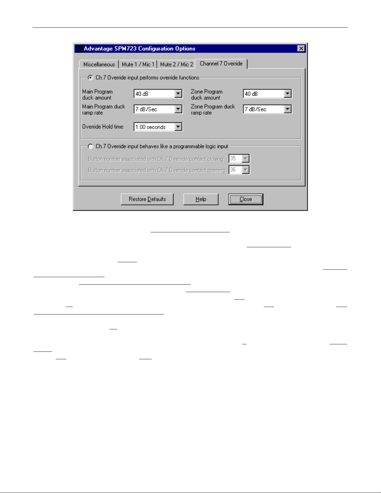
CHANNEL 7 OVERRIDE SCREEN
The Configuration Options screen is accessed through the Configure SPM723 menu, and the Channel 7 Override
Options screen is then used to select options which customize the function of the Override terminal (see Front & Rear Panel Features on
pg. 3). When Channel 7 Override is released
these signals will initially be attenuated, and will then return to their normal levels as determined by the following parameters. Main Duck
Amount & Zone Duck Amount open drop-down menus of 41 attenuation choices (0dB~80dB) for the stereo Line Input signals at the
associated output. Main Duck Ramp Rate & Zone Duck Ramp Rate
second) for the stereo Line Input signals at the associated output. Override Hold Time
(0~63.75 seconds). NOTE: Hold Time determines how long override remains in effect after
Hold Time is not
Override Input Behaves Like a Programmable Logic Input will disable the Channel 7 Override functions described above, and instead allow
the Override terminal to be used as a logic input, which can then be programmed like a remote control button (see Setup on pg. 8).
However, a logic input can have two
‘opened’ (released). Therefore, drop-down menus of the forty possible control buttons are provided for both the ‘closing’ & the ‘opening’ of
the logic input circuit. The logic input can still be triggered manually (via contact-closure) or
Defaults opens a pop-up menu, which allows the Channel 7 Override options (or all Configuration Options) to be set back to their factory
defaults. Help
the same as Ramp Rate, which determines how fast a signal returns to normal after Hold Time has elapsed. Ch.7
‘button definitions’, one for when the circuit is ‘closed’ (activated) and another for when the circuit is
provides additional instruction. Close will return you to the Mix screen.
, the previously selected Stereo Line Inputs for each output will again be selected. However,
open drop-down menus of 200 return rate choices (1dB~200dB per
opens a drop-down menu of 256 hold time choices
triggering (manual or automatic) is released.
automatically (via signal present). Restore
tab on the Configuration
13
Page 16

LOGIC INPUTS
Eight Logic Inputs are available on a rear panel 9-pin Sub-D (female) connector. Logic Inputs allow remote control of the SPM723 via
external circuits, such as switches, contact-closures, active driver circuits, and/or ‘open-collector’ logic outputs. From the factory, Logic
Inputs 1~8 have no pre-programmed function. However, each Logic Input may be assigned different ‘actions’ using the BiampWin
software and serial cable provided with the SPM723 (see Setup on pg. 9). Since Logic Inputs are controlled by switches, contact-closures,
etc., each Logic Input may be assigned two functions (one for switch ‘closed’ and one for switch ‘open’).
Logic Inputs have the following pin assignments
(right-to-left & top-to-bottom): Pins 1~8) Logic Inputs 1~8; Pin 9) Ground.
12345
6789
pin #1 = Logic Input 1
pin #2 = Logic Input 2
pin #3 = Logic Input 3
pin #4 = Logic Input 4
pin #5 = Logic Input 5
pin #6 = Logic Input 6
pin #7 = Logic Input 7
pin #8 = Logic Input 8
pin #9 = ground
logic inputs
When nothing is connected to a Logic Input, an internal pull-up resistor keeps it at a ‘high’ idle state (+5.0 VDC). The Logic Input is
activated when its input goes ‘low’ (less than +0.8 VDC), and is de-activated when its input goes ‘high’ (greater than +2.4 VDC). A Logic
Input is controlled in one of three ways: 1) Use an NPN style ‘open-collector’ logic output from an external device (such as a BIAMP
PMX84 or DRC4+4) to short the Logic Input to ground. 2) Use a switch, relay, or other contact-closure (such as from a third-party
controller) to short the Logic Input to ground. 3) Use an active TTL output driver circuit (such as from a third-party controller) to actively
drive the Logic Input to a ‘high’ or ‘low’ state.
Multiple contact-closures or ‘open-collector’ logic outputs may be wired in parallel to a single Logic Input (see diagram below). Logic
Outputs and contact-closures should be rated for at least 5 Volts / 1mA operation. Low-current / dry-contact closures are recommended
for reliability. Active output driver circuits should not exceed a signal range of 0~5 Volts DC, and should have a minimum pulse width of
100 milli-seconds. Logic Input impedances are approximately 10k ohms.
multiple switches to single Logic Input
14
Page 17

LOGIC OUTPUTS
The SPM723 provides eight logic outputs on a rear panel 9-pin Subminiature D (male) connector. Logic Outputs can be used to control
external circuits such as relays, indicators, etc. (see diagrams below). However, the SPM723 Logic Outputs are most often used to provide
simultaneous audio & video source selection, by controlling an external video switching device which has logic inputs or other means of
control via external contact-closures (logic outputs). Multiple Logic Outputs may be combined (wired in parallel) to control a single circuit.
The SPM723 Logic Outputs are ‘open collector’ outputs. Each Logic Output is an NPN transistor with the collector being the output and the
emitter being ground (see diagram below). When a Logic Output is turned on, the transistor provides a path for DC current to flow. The
Logic Outputs do not provide any voltage or current. They act only as switches (with a common ground return). To activate external
relays, an external power supply must be used (see diagram below). The Logic Output transistors are rated up to a maximum of 24 VDC
and 50 mA per output (24 volt relay coils maximum). However, +12 Volts DC is sufficient power for most applications. When using the
Logic Outputs to control relays, protection diodes must be used to suppress high voltage transients that are generated when the relays turn
off (see diagram below). Any of the 1N4004 family of diodes (1N4001, 1N4002, 1N4003, 1N4004, 1N4005, 1N4006, 1N4007, or
equivalent) will provide proper protection. When a Logic Output goes on, the associated relay may be wired to perform on, off, or ’A/B’
switching functions. To use logic ‘on’ to turn on (or activate) a device, wire across the ‘normally open’ relay contacts, in series with the
device (or control voltage source). To use logic ‘on’ to select between ‘A’ or ‘B’ signals (inputs or outputs), wire one signal to the ‘normally
closed’ relay terminal and the other signal to the ‘normally open’ relay terminal, with the common relay terminal providing the feed (input or
output).
12345
6789
logic
outputs
Logic Output Controlling Relay
SPM723
Pin #1
Logic Output #1
logic out pin number
Logic Out 1
Logic Out 2
Logic Out 3
Logic Out 4
Logic Out 5
Logic Out 6
Logic Out 7
Logic Out 8
ground
pin #1
pin #2
pin #3
pin #4
pin #5
pin #6
pin #7
pin #8
pin #9
+12 Volts DC
Power Supply
−+
1N4004
Diode
5
4
3
2
1
9
8
7
6
9-pin cable-end
12V Relay
Contacts
normally closed
normally open
common
Coil
Logic Output #1
Pin #9
Logic Output Controlling LED Indicator
SPM723 +12 Volts DC
Power Supply
Pin #1
Pin #9
−+
15
Indicator Panel
1.2k ohms
LED
Page 18
RS-232 CONTROL
The SPM723 has an RS-232 Serial Port, which allows it to be controlled by a computer (see Front & Rear Panel Features on pg. 2). In
addition to the BiampWin software, the SPM723 offers two other methods of computer control.
Control Button Emulation: This method allows the computer to imitate the operation of an infrared transmitter or wall-mount control
panel. Although the SPM723 does not accept infrared or wall-mount remote controls itself, it can still receive ASCII characters (via RS-
232) which emulate the buttons on these types of remote controls. From the factory, remote control buttons have equivalent ASCII
characters permanently assigned to them (see table below). Therefore, actions can be assigned to remote control buttons in the same
way they are assigned to Logic Inputs. Then, using this method, the computer can output ASCII characters which are equivalent to the
commands generated by those standard remote control buttons. Control Button Emulation allows the computer to utilize up to forty button
definitions (unlike standard remote controls, which have only twenty-eight buttons).
Advanced Computer Control: This method provides advanced commands, which allow the computer to retrieve or edit various SPM723
settings. The computer may also emulate control buttons. Using this method, the computer may designate up
may also provide ‘real-time’ display of various settings.
This manual only describes the Control Button Emulation method of computer control. For details regarding Advanced Computer Control,
please download the SPM723 Computer Control manual (723host.PDF) from the ‘resources’ page of our web site (www.biamp.com).
Each control button on an infrared transmitter or wall-mount control panel corresponds to one character in the standard ASCII character
set. The character equivalents are summarized in the following table. This table includes all forty possible buttons, their button numbers,
their ASCII code equivalents, and their factory default button definitions (no operation assigned).
button 01 B no operation assigned button 15 P no operation assigned button 29 ^ no operation assigned
button 02 C no operation assigned button 16 Q no operation assigned button 30 _ no operation assigned
button 03 D no operation assigned button 17 R no operation assigned button 31 ' no operation assigned
button 04 E no operation assigned button 18 S no operation assigned button 32 b no operation assigned
button 05 F no operation assigned button 19 T no operation assigned button 33 c no operation assigned
button 06 G no operation assigned button 20 U no operation assigned button 34 d no operation assigned
button 07 H no operation assigned button 21 V no operation assigned button 35 e no operation assigned
button 08 I no operation assigned button 22 W no operation assigned button 36 f no operation assigned
button 09 J no operation assigned button 23 X no operation assigned button 37 g no operation assigned
button 10 K no operation assigned button 24 Y no operation assigned button 38 h no operation assigned
button 11 L no operation assigned button 25 Z no operation assigned button 39 i no operation assigned
button 12 M no operation assigned button 26 [ no operation assigned button 40 j no operation assigned
button 13 N no operation assigned button 27 \ no operation assigned
button 14 O no operation assigned button 28 ] no operation assigned
The computer can initiate any functions or actions that a standard control can, by simply transmitting the equivalent control button ASCII
character. When interfacing the SPM723 to a computer, the computer must be aware that the SPM723 will ‘echo’ all characters it receives
(both from computer and Logic Inputs) via the Serial Port Transmit Data (TXD) output signal. However, from the factory, the SPM723
Logic inputs are programmed with no ‘echo character’ assigned to them.
to sixty-four devices, and
16
Page 19

RS-232 CONTROL
Serial Port: The 9-pin Sub-D (male) connector on the SPM723 rear panel provides the RS-232 compatible serial interface signals used for
computer control. The SPM723 Serial Port transmits serial data on pin 3 (TxD), receives serial data on pin 2 (RxD), and provides a ground
on Pin 5. The Data Terminal Ready (DTR) & Request To Send (RTS) output signals are connected to the +12 Volt power supply (through
a resistor) and are always asserted when the SPM723 power is on. NOTE: The Serial Port may also transmit commands which are
received via the Logic Inputs, depending upon the echo character assignments (see Setup on pg. 9).
54321
pin #1 = not used
pin #2 = Receive Data (RxD) input
pin #3 = Transmit Data (TxD) output
9876
pin #4 = Data Terminal Ready (DTR) output
pin #5 = ground
pin #6 = not used
pin #7 = Request To Send (RTS) output
pin #8 = not used
pin #9 = not used
serial port
The SPM723 only requires receive data (pin 2), transmit data (pin 3), and signal ground (pin 5) to be connected for successful data
communications (see cable diagram below). However, the PC may require that signals be present on the data set ready, clear to send, or
carrier detect inputs, as well as the receive data, transmit data, and signal ground pins. Success or failure depends entirely on the actual
computer hardware and software being used. When trying to solve an interfacing problem, the most important thing to remember is that an
output of one device should connect to one or more inputs of the other device, and that two outputs should never be connected together.
Also, keep in mind that the RS-232 specification calls for the cable length to be no greater than 50 feet (although it is not unusual to be
able to operate over distances of 150 to 250 feet), and the connectors must be of the appropriate gender (male or female) to mate
properly. For best results, a shielded cable should be used, with the shield connected to chassis ground. Since the SPM723 serial
interface ground is also tied (indirectly) to the analog signal ground, undesirable ground loops may occur when the SPM723 is connected
to a PC (if the system grounding is not carefully designed). For best performance, the PC ground and the chassis ground of the SPM723
should be at the same potential, and the PC should get AC power from the same source as the SPM723 (and any other audio equipment
which is connected to the SPM723). Since most lap-top computers are isolated from earth ground, this should rarely pose a problem.
Serial Port Data Communications Parameters: The SPM723 communicates through the Serial Port at the factory default rate of 38400
bits per second, with 8 data bits, 1 stop bit, and no parity. The SPM723 utilizes a subset of the standard 7-bit ASCII character set. The
eighth data bit of each character (the most significant bit) should always be 0. The computer should not echo the characters it receives.
The computer should not be set for either hardware (DTR) or software (XON/XOFF) flow control. The baud rate may be changed to either
2400, 9600, or 19200 bits per second by means of the software (see Setup on pg. 4). NOTE: Baud rate may need to be changed when
the SPM723 is being used in RS-232 systems with other products having a lower maximum baud rate.
Link Port Connections: The 9-pin Sub-D (female) connector on the SPM723 rear panel provides the RS-232 compatible serial interface
signals used for linking multiple BIAMP
®
products within a system. The Link Port of one device simply connects to the Serial Port of the
next device, and so forth (see diagram below). Link cables are available as an option (Biamp #909-0057-00). NOTE: All but the final
device in a system should have its ‘Link’
switch pressed in (see Front & Rear Panel Features on pg. 2). The Link Port may also transmit
commands which are received via the Logic Inputs, depending upon the echo character assignments (see Setup on pg. 9).
12345
pin #1 = not used
pin #2 = Transmit Data (TxD) output
pin #3 = Receive Data (RxD) input
6789
pin #4 = not used
pin #6 = not used
pin #7 = not used
pin #8 = not used
pin #9 = not used
pin #5 = ground
link port
PC
CD
RxD
TxD
DTR
gnd
DSR
RTS
CTS
RI
serial port
1
1
2
2
3
3
4
4
5
5
6
6
7
7
8
8
9
9
male female
Serial Cable
(shield)
serial port
1
1
2
2
3
3
4
4
5
5
6
6
7
7
8
8
9
9
female male
SPM723
n/a
RxD
TxD
DTR
gnd
n/a
RTS
n/a
n/a
SPM723
n/a
TxD
RxD
n/a
gnd
n/a
n/a
n/a
n/a
link port
1
2
3
4
5
6
7
8
9
female male
1
2
3
4
5
6
7
8
9
Link Cable
(shield)
serial port
1
1
2
2
3
3
4
4
5
5
6
6
7
7
8
8
9
9
female male
unit 2
n/a
RxD
TxD
DTR
gnd
n/a
RTS
n/a
n/a
17
Page 20

SPECIFICATIONS & BLOCK DIAGRAM
______________________________________________
Frequency Response (20Hz-20kHz @ +4dBu): +0/-0.5dB
THD + Noise (20Hz-20kHz @ +4dBu): < 0.05%
Output Noise (20Hz-20kHz @ nominal levels): < -73dBu
Equivalent Input Noise (20Hz-20kHz, 150Ω @ Mic/Line Input): -127dBu
Maximum Gain (Mic/Line Input to Main/Zone Outputs): 75dB
Input Trim Gain Range:
Mic/Line Inputs +60dB to -6dB
Input Impedance:
Mic/Line Inputs (balanced)
Stereo Line Inputs 1~6 (unbalanced)
Line Input 7 (stereo/unbalanced)
Line Input 7 (mono/balanced)
Maximum Input:
Mic/Line Inputs (balanced)
Stereo Line Inputs 1~6 (unbalanced)
Line Input 7 (stereo/unbalanced – mono/balanced)
SPECIFICATIONS
6.6k ohms
10k ohms
10k ohms
20k ohms
+24dBu
+18dBu
+18dBu
SPM723 Block Diagrm
______________________________________________
Output Impedance:
Main Output (balanced)
Zone Output (balanced)
Aux Output (balanced)
Maximum Output:
Main Output (balanced)
Zone Output (balanced)
Aux Output (balanced)
Phantom Power (Mic/Line Inputs only): +24 Volts DC
Power Requirements: 110/220VAC 50/60Hz
Power Consumption: 27 Watts max.
Dimensions:
height (1 rack space)
width
depth
Weight:
200 ohms
200 ohms
200 ohms
+24dBu
+24dBu
+24dBu
1.75 inches (89mm)
19 inches (483mm)
11 inches (191mm)
< 10 lbs. (3.86kg)
stereo line
input (1~5)
stereo line
input 6
stereo line
input 7
mic/line
input 1
+24V
mic/line
input 2
+24V
x5
trim
trim
mono/
stereo
hpf
hpf
EQ
EQ
+6dB
main
zone
main
zone
aux
surround
main
zone
main
zone
main
zone
main
zone
EQ
EQ
aux output
source select
EQ
serial
in/out
mute logic
mic 1
mic 2
ch. 7
mono/
stereo
mono/
stereo
meter inputs
mono/
stereo
switches
and
controls
uC
mic 1
mic 2
ch 7
main
zone
aux
main
output
zone
output
logic out
logic in
aux
output
8
8
18
Page 21

WARRANTY
BIAMP SYSTEMS IS PLEASED TO EXTEND THE FOLLOWING 5-YEAR LIMITED WARRANTY TO THE
ORIGINAL PURCHASER OF THE PROFESSIONAL SOUND EQUIPMENT DESCRIBED IN THIS MANUAL
1. BIAMP Systems warrants to the original purchaser of new
products that the product will be free from defects in material
and workmanship for a period of 5 YEARS from the date of
purchase from an authorized BIAMP Systems dealer, subject to
the terms and conditions set forth below.
2. If you notify BIAMP during the warranty period that a BIAMP
Systems product fails to comply with the warranty, BIAMP
Systems will repair or replace, at BIAMP Systems' option, the
nonconforming product. As a condition to receiving the benefits
of this warranty, you must provide BIAMP Systems with
documentation that establishes that you were the original
purchaser of the products. Such evidence may consist of your
sales receipt from an authorized BIAMP Systems dealer.
Transportation and insurance charges to and from the BIAMP
Systems factory for warranty service shall be your responsibility.
3. This warranty will be VOID if the serial number has been
removed or defaced; or if the product has been altered,
subjected to damage, abuse or rental usage, repaired by any
person not authorized by BIAMP Systems to make repairs; or
installed in any manner that does not comply with BIAMP
Systems' recommendations.
4. Electro-mechanical fans, electrolytic capacitors, and normal
wear and tear of items such as paint, knobs, handles, and
covers are not covered under this warranty.
Biamp Systems
10074 S.W. Arctic Drive
Beaverton, Oregon 97005
(503) 641-7287
5. THIS WARRANTY IS IN LIEU OF ALL OTHER
WARRANTIES, EXPRESS OR IMPLIED. BIAMP SYSTEMS
DISCLAIMS ALL OTHER WARRANTIES, EXPRESS OR
IMPLIED, INCLUDING, BUT NOT LIMITED TO, IMPLIED
WARRANTIES OF MERCHANTABILITY AND FITNESS FOR A
PARTICULAR PURPOSE.
6. The remedies set forth herein shall be the purchaser's sole
and exclusive remedies with respect to any defective product.
7. No agent, employee, distributor or dealer of Biamp Systems
is authorized to modify this warranty or to make additional
warranties on behalf of Biamp Systems. statements,
representations or warranties made by any dealer do not
constitute warranties by Biamp Systems. Biamp Systems shall
not be responsible or liable for any statement, representation or
warranty made by any dealer or other person.
8. No action for breach of this warranty may be commenced
more than one year after the expiration of this warranty.
9. BIAMP SYSTEMS SHALL NOT BE LIABLE FOR SPECIAL,
INDIRECT, INCIDENTAL, OR CONSEQUENTIAL DAMAGES,
INCLUDING LOST PROFITS OR LOSS OF USE ARISING OUT
OF THE PURCHASE, SALE, OR USE OF THE PRODUCTS,
EVEN IF BIAMP SYSTEMS WAS ADVISED OF THE
POSSIBILITY OF SUCH DAMAGES.
585.0160.00
Page 22

Declaration of Conformity
Biamp Systems, Inc., as the manufacturer, hereby declares that the following described product, in our
delivered version, complies with the provisions of the DIRECTIVES except as noted herein. In case of
alteration of the product, not agreed upon or directed by us, this declaration is no longer valid.
Product Model: ADVANTAGE
Product Description: Digitally Controlled Stereo Preamp/Mixer
Applicable EC Directives: EMC Directive (89/336/EEC), LVD Directive (73/23/EEC)
Applicable Harmonized Standards: EN55103-1 emissions EN55103-2 immunity EN60065 safety
Special Considerations for Product Environment or Compliance:
Shielded cabling must be used for system connections. The apparatus is deemed incapable of
producing harmonic emissions or flicker levels sufficient enough to interfere with other apparatus as
noted in EN61000-3-2 and EN61000-3-3.
This apparatus operates from a removeable external power source at voltages below the levels
encompassed by the LVD. The external power source complies with the applicable requirements of
EN60065. The apparatus itself is outside of the scope of the LVD and presents no hazardous
voltages, as defined in the LVD. For compliance, the apparatus shall be powered only from the
separate CE marked Biamp Systems power source.
RF interference conducted through interconnect cabling may cause varying degrees of random
signal degradation. The effect of increased noise or distortion due to this interference is typically
masked by the desired signal. In no instance is operation inhibited.
The Technical Report/File is maintained at: Biamp Systems, Inc.
10074 S.W. Arctic Drive
Beaverton, OR USA 97005
phone: (503) 641-7287 fax: (503) 626-0281
e-mail: biamp@biamp.com
Authorized Representative: Steven Hedgepeth
Authorized Representative Signature:
Issued: June, 2000
SPM723
Page 23

Page 24

Page 25

 Loading...