

Page 1
SPM412e
Controller
Instructions
Biamp Systems | 9300 S.W. Gemini Drive | Beaverton, OR | 97008 | USA | +1.503.641.7287 | www.biamp.com
Page 2
SPM412e Controller Instructions
Controller: The Controller is a ‘hard-wired’ control, which is powered by
the SPM412e. There are no batteries to wear out, and it is not easily
lost or stolen. The Controller may be wired up to 2000 feet from the
SPM412e, using 2-conductor shielded cable (not included). The
Controller overrides all similar commands which might be initiated from
the front panel of the SPM412e (see NOTE below). To install Controller,
first remove mounting box from circuit board & front panel. Route cable
through ‘knock-out’ hole on rear of mounting box. Install mounting box in
wall or panel. Three screw terminals on circuit board (‘GND’, ‘IR2’, &
‘IR3’) correspond to ‘Remote’ terminals on rear panel of SPM412e.
Connect cable shield to ‘GND’ terminals at each end. Use conductors to
connect ‘IR2’ to ‘IR2’ and ‘IR3’ to ‘IR3’. Install circuit board & front panel
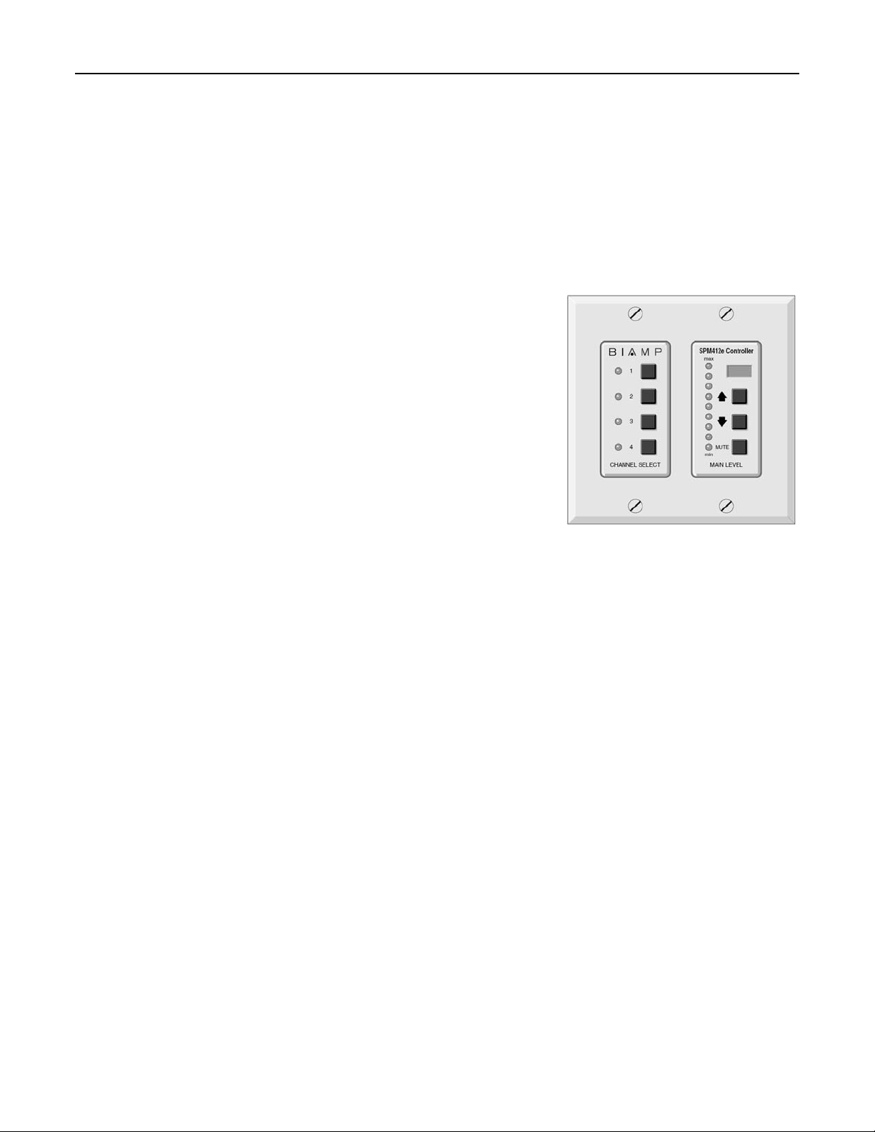
on mounting box. The Controller has seven buttons which control
functions on the SPM412e. The Channel Select buttons & indicators
provide the same functions as Channel Select on the SPM412e front
panel (including the ability to select more than one stereo line input at a
time). The Main Level buttons and display provide the same functions
as Main Level on the SPM412e front panel, except that only a single
indicator will light to display the level setting, and it will dim when the
output is muted.
NOTE: Two additional screw terminals (‘GND’& ‘KEY SWI’) allow an
external key-switch (or contact-closure) to ‘lock-out’ control of Channel
Select and/or Main Level functions. These functions will then be
temporarily available from the SPM412e front panel, as long as the ‘lockout’ is maintained. When ‘lock-out’ is released, the Controller memory
will then reassert its previous settings on the SPM412e. A 4-gang DIP
switch on the Controller circuit board allows custom functions to be
assigned, such as Channel Select ‘lock-out’, Main Level ‘lock-out’, keylock normally-open/closed, and infrared detector defeat (see Installation
on page 2).
1
Page 3

SPM412e Controller Installation
The Controller is a ‘hard-wired’ control, which is
powered by the SPM412e. There are no batteries to
wear out, and it is not easily lost or stolen. The
Controller may be wired up to 2000feet away from the
SPM412e, using 2-conductor shielded cable (not
included).
Remove the mounting box from the front panel.Route
the cable through a ‘knock-out’ hole on the rear of the
mounting box. Install the mounting box in a wall or
panel, in the same orientation as any standard doublewide electrical box (do not rotate 90° as with other
Advantage Wall-Mount panels).
The mounting surface may be from 1/8” to 1” thick.
(3.175mm to 25.4mm)
The mounting cavity must be exactly 3.6 inches
high, 4 inches wide, and at least 2.65 inches deep.
(91.44mm x 101.6mm x 67.31mm)
Insert the mounting box into the wall or panel, then
tighten the flange screws until the flanges hold the box
securely in place. Three screw terminals on the circuit
board (‘GND’, ‘IR2’, and ‘IR3’) directly correspond to
‘Remote’ terminals on the rear panel of the SPM412e.
Connect the cable shield to the ‘GND’ terminal at each
end. Use the two conductors to connect ‘IR2’ to ‘IR2’
and ‘IR3’ to ‘IR3’.
A key-switch may be wired across the ‘KEY SWI’ and adjacent
‘GND’ terminals, allowing ‘user lock-out’ of certain Controller
functions. DIP switches are provided to defeat the front panel
infrared detector, and to customize the key switch functions. The
‘IR’ DIP switch completely disables infrared control. The ‘CHAN’
DIP switch disables both push-button and infrared control of
Channel Select. The ‘VOL’ DIP switch disables both push-button
and infrared control of Main Level. (NOTE: DIP switches must be
pushed to the right to achieve the functions described above.) If
Channel Select and/or Main Level control is disabled via the DIP
switches, it may be re-enabled via the key-switch. The ‘N.O.’ DIP
switch selects either a ‘normally open’ or ‘normally closed’ keyswitch operation. When this DIP switch is pushed left, a
‘normally-open’ key-switch must be turned ON (shorting ‘KEY
SWI’ & ‘GND’ terminals) to re-enable Channel Select and/or
Main Level control. When this DIP switch is pushed right, a
‘normally-closed’ key-switch must be turned OFF (‘KEY SWI’
terminal not grounded) to re-enable Channel Select and/or Main
Level control. Factory setting is with all DIP switches left.
Install the front panel in the mounting box, using the four
screws provided. Appropriate indicators on the face plate will
light when power is delivered to the Controller.
Mounting Box
SPM412e controller board
GND
IR2
IR3
IR
CHAN
VOL
N.O.
KEYSWITCH
1234
N
O
GND
KEY
SWI
2
Page 4

DoC SPM201003
EC Declaration of Conformity
Biamp Systems Corporation, as manufacturer having sole responsibility, hereby
declares that the following described product complies with the applicable provisions of
the DIRECTIVES below except as noted herein. Any alterations to the product not
agreed upon and directed by Biamp Systems Corporation will invalidate this declaration.
Product Model: SPM412e and SPM412e Controller
Product Description: Stereo Program Mixer
Applicable EC Directives: Applicable Harmonized Standards:
LVD Directive (2006/95/EC) Safety EN 60065:2002
EMC Directive (2004/108/EC) Emissions EN 55103-1:1996, Environment E2
Immunity EN 55103-2:1996
Special Considerations for Product Environment or Compliance:
Use only Biamp Systems supplied 24 VDC External Power Supply Adaptor.
Shielded cabling must be used for system connections.
Technical Construction File, Location and Contact:
Biamp Systems, Inc. phone: (503) 641.7287
9300 S.W. Gemini Drive fax: (503) 626.0281
Beaverton, OR USA 97008 e-mail: biamp@biamp.com
Authorized Representative: Larry Copley, Compliance Engineer
Authorized Signature:
Issued: March, 2010
Page 5

 Loading...