

Page 1
TABLE OF CONTENTS
Connections
RS-232
Remote Controls
Application
Warranty
CE Documents
Safety Information
TM
RT
Remote Translator
–––– and ––––
WMC, IR-T, & RIK
Controls
Operation Manual
pg. 2
pg. 3
pg. 5
pg. 8
pg. 9
INTRODUCTION
The RT Remote Translator allows remote control of BIAMP programmable
products, such as VRAM, MSP22e, & SPM723, via standard wall-mount &
infrared controls, including WMC, IR-T, & RIK. The RT converts control button
data into RS-232 characters, which can be programmed on a per product
basis. Therefore, controls can be customized to control a variety of level,
muting, source selection, & recall preset functions within a system having
multiple BIAMP products. The RT carries a five-year warranty.
RT features include:
♦ RS-232 serial & link ports for communication with products
♦ 2 remote ports accept any combination of standard controls
♦ supports Biamp standard controls (WMC, IR-T, & RIK)
♦ WMC - 2-gang wall-mount control panel (28 buttons)
♦ RIK - circuit board for custom-built panels (up to 40 buttons)
♦ IR-T - hand-held infrared transmitter control (28 buttons)
♦ individual product software assigns functions to push-buttons
♦ power & data LED indicators for easy trouble-shooting
♦ back panel key-holes provided for convenient mounting
♦ covered by Biamp Systems’ five-year warranty
♦ incorporates AES recommended grounding practices
♦
marked and UL / C-UL listed power source
1
Page 2
CONNECTIONS
27V
~
50/60 Hz
15 watts
class 2 wiring
serial port
RCU
power
data
gnd
IR2
IR3
gnd
IR2
IR3
link port
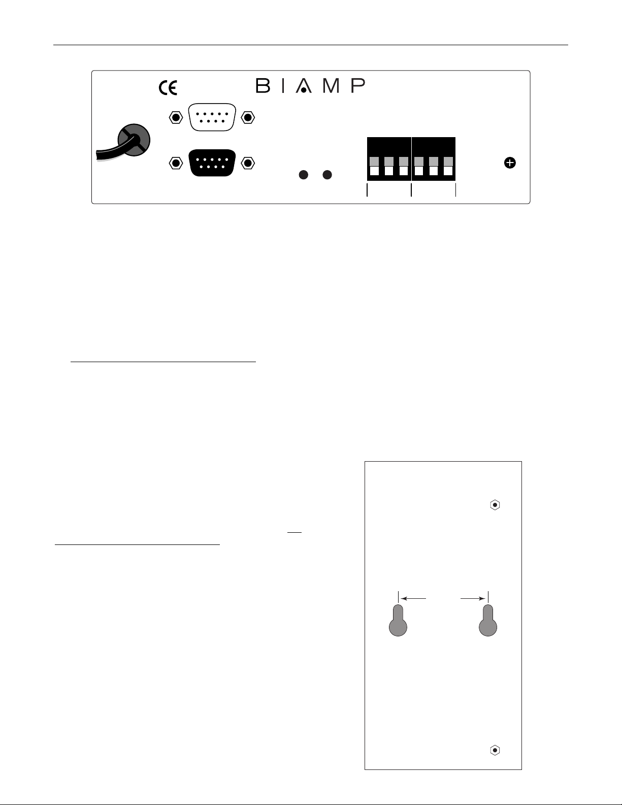
AC Power Cord: The power transformer provides 27 Volts AC to
the RT, and is detachable via a 5-pin DIN connector. The RT has
two internal ‘self-resetting’ fuses (there are no user serviceable
parts inside the unit). If the internal fuses blow, they will attempt to
re-set after a short period. However, this may be an indication that
the RT requires service.
Serial Port: This 9-pin Sub-D (male) connector provides an RS232 Serial Port for added control of the associated system
products via software or third-party controllers (see RS-232 on pg.
3). The Serial Port has the following pin assignments
(left-to-right
& top-to-bottom): Pin 1) not used; Pin 2) Receive Data (RxD)
input; Pin 3) Transmit Data (TxD) output; Pin 4) Data Terminal
Ready (DTR) output; Pin 5) Ground; Pin 6) not used; Pin 7)
Request To Send (RTS) output; Pin 8) not used; Pin 9) not
used. NOTE: Typically, nothing is connected at the RT Serial
Port, unless software or a third-party controller is also being used
for system control (in addition to the infrared & wall-mount pushbutton remote controls).
Link Port: This 9-pin Sub-D (female) connector provides a Link
Port for RS-232 control from the RT to other BIAMP programmable
products (see RS-232 on pg. 3). The Link Port of one device
simply connects to the Serial Port of the next device (and so forth).
A Serial Link Cable is included with the RT for this purpose. The
Link Port has the following pin assignments (right-to-left & top-tobottom): Pin 1) not used; Pin 2) Transmit Data (TxD) output;
Pin 3) Receive Data (RxD) input; Pin 4) not used; Pin 5)
Ground; Pin 6) not used; Pin 7) not used; Pin 8) not used;
Pin 9) not used. NOTE: The Link Port transmits 'equivalent
ASCII characters' which correspond to the 'button' commands
received via Remote 1 & 2, and will also ‘echo’ RS-232 commands
received at the Serial Port (from computers or third-party
controllers.
remote 1 remote 2
Power Indicator: When the power transformer is plugged in, and
AC power is applied to the RCU, the Power indicator remains lit.
Data Indicator: Whenever the RT receives remote control button
commands at Remote 1 or Remote 2, the Data Indicator will flash.
Remote 1 & 2: These two plug-in barrier strips accept 'button'
commands from optional remote controls (see Remote Controls on
pg. 5). Remote Controls may be infrared, wall-mount, or custom
panels, and may be wired up to 2000 feet away from the RT. The
RT converts the remote control 'button' commands into
corresponding RS-232 'equivalent ASCII characters'. The function
of these 'equivalent ASCII characters' is then programmed on a
per product basis, by means of the Button Definition screen found
in the software program for each product to be controlled.
Key-Holes: Two key-holes are provided on the rear panel of the
RT, for convenient mounting (see diagram below).
1.75 inches
RT
rear panel
key-hole
mounting
2
Page 3
RS-232
The RT has an RS-232 Serial Port, which allows it to pass RS-232 commands from computers or third-party controllers, and a Link Port,
which allows the RT itself to transmit 'equivalent ASCII characters', to BIAMP programmable products (see Connections on pg. 2).
Control Button Emulation: Control Button Emulation is the process by which the RT converts infrared or wall-mount control 'button'
commands (received at Remote 1 or Remote 2) into RS-232 'equivalent ASCII characters' (transmitted at the RS-232 Link Port). From the
factory, remote control buttons on BIAMP programmable products have equivalent ASCII characters permanently assigned to them (see
table below). Therefore, actions can be assigned to remote control buttons during the programming of these products. Using this method,
the RT can output (to the other products) ASCII characters which are equivalent to the commands generated by remote control buttons.
For more information, see the manual or BiampWin software program (Button Definition screen) for the products to be controlled.
Each control button on an infrared transmitter or wall-mount control panel corresponds to one character in the standard ASCII character
set. The character equivalents are summarized in the following table. This table includes all forty possible buttons, their button numbers,
and their 'equivalent ASCII characters'. Their button definitions are then defined during programming of the product to be controlled.
button 01 B programmable by product button 15 P programmable by product button 29 ^ programmable by product
button 02 C programmable by product button 16 Q programmable by product button 30 _ programmable by product
button 03 D programmable by product button 17 R programmable by product button 31 ' programmable by product
button 04 E programmable by product button 18 S programmable by product button 32 b programmable by product
button 05 F programmable by product button 19 T programmable by product button 33 c programmable by product
button 06 G programmable by product button 20 U programmable by product button 34 d programmable by product
button 07 H programmable by product button 21 V programmable by product button 35 e programmable by product
button 08 I programmable by product button 22 W programmable by product button 36 f programmable by product
button 09 J programmable by product button 23 X programmable by product button 37 g programmable by product
button 10 K programmable by product button 24 Y programmable by product button 38 h programmable by product
button 11 L programmable by product button 25 Z programmable by product button 39 i programmable by product
button 12 M programmable by product button 26 [ programmable by product button 40 j programmable by product
button 13 N programmable by product button 27 \ programmable by product
button 14 O programmable by product button 28 ] programmable by product
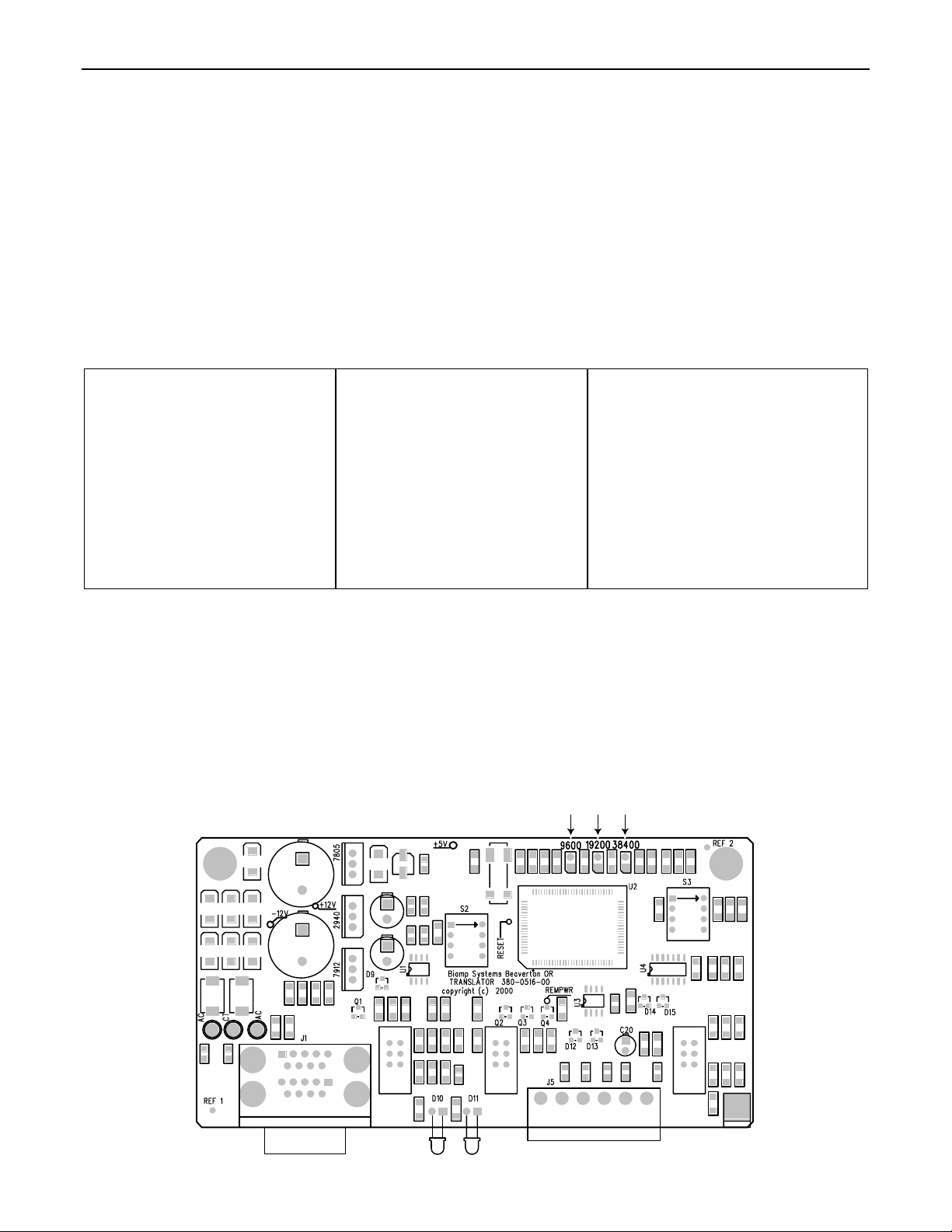
Baud Rate Jumper: To communicate properly with all products in the system, a common RS-232 baud rate must be used. The RT is
shipped from the factory with a default baud rate of 38,400. This baud rate corresponds with the current default baud rate of the most
commonly associated Biamp programmable products. However, in some cases the RT baud rate may need to be changed to match that
of other devices being used in the system. The RT has an internal jumper strap that allows an optional baud rate of either 9600 or 19,200
to be selected. To select an optional baud rate: 1) Remove power from the RT. 2) Remove the RT cover. 3) Lift the jumper strap from
the currently selected baud rate pins (see diagram below). 4) Replace it on the pins provided for the desired baud rate. 5) Replace the
RT cover. 6) Connect power to the RT. NOTE: Power to the RT must be turned off during this modification, not only as a safety
precaution, but also because Baud Rate changes will not take affect until power has been cycled.
baud rate jumper positions
RT pcb
3
Page 4

RS-232 CONTROL
Serial Port: The 9-pin Sub-D (male) connector provides the RS-232 compatible serial interface signals used for computer (or third-party)
control of the system. The RT Serial Port transmits serial data on pin 3 (TxD), receives serial data on pin 2 (RxD), and provides a ground
on Pin 5. The Data Terminal Ready (DTR) & Request To Send (RTS) output signals are connected to the +12 Volt power supply (through
a resistor) and are always asserted when the RT power is on. NOTE: Typically, nothing is connected at the RT Serial Port, unless
software or a third-party controller is also being used for system control (in addition to the infrared & wall-mount push-button remote
controls).
54321
pin #1 = not used
pin #2 = Receive Data (RxD) input
pin #3 = Transmit Data (TxD) output
9876
serial port
pin #4 = Data Terminal Ready (DTR) output
pin #5 = ground
The RT only requires receive data (pin 2), transmit data (pin 3), and signal ground (pin 5) to be connected for successful data
communications (see cable diagram below). However, the PC may require that signals be present on the data set ready, clear to send, or
carrier detect inputs, as well as the receive data, transmit data, and signal ground pins. Success or failure depends entirely on the actual
computer hardware and software being used. When trying to solve an interfacing problem, the most important thing to remember is that an
output of one device should connect to one or more inputs of the other device, and that two outputs should never be connected together.
Also, keep in mind that the RS-232 specification calls for the cable length to be no greater than 50 feet (although it is not unusual to be
able to operate over distances of 150 to 250 feet), and the connectors must be of the appropriate gender (male or female) to mate
properly. For best results, a shielded cable should be used, with the shield connected to chassis ground. Undesirable ground loops may
occur when the RT is connected to a PC (if the system grounding is not carefully designed). For best performance, the PC ground and the
chassis ground of the RT should be at the same potential, and the PC should get AC power from the same source as the RT (and any
other audio equipment which is connected to the RT). Since most lap-top computers are isolated from earth ground, this should rarely
pose a problem.
Serial Port Data Communications Parameters: The RT communicates through the Serial Port at the factory selected rate of 38,400 bits
per second, with 8 data bits, 1 stop bit, and no parity. The RT utilizes a subset of the standard 7-bit ASCII character set. The eighth data
bit of each character (the most significant bit) should always be 0. The computer should not echo the characters it receives. The computer
should not be set for either hardware (DTR) or software (XON/XOFF) flow control. The baud rate may be changed to either 9600 or
19,2000 bits per second by means of an internal jumper (see Baud Rate Jumper on previous page).
Link Port Connections: The 9-pin Sub-D (female) connector provides the RS-232 compatible serial interface signals used for RT control
of BIAMP programmable products within a system. The Link Port of one device simply connects to the Serial Port of the next device, and
so forth (see diagram below). NOTE: The Link Port transmits 'equivalent ASCII characters' which correspond to the 'button' commands
received via Remote 1 & 2, and will also ‘echo’ RS-232 commands received at the Serial Port (from software or a third-party controller).
12345
pin #1 = not used
pin #2 = Transmit Data (TxD) output
pin #3 = Receive Data (RxD) input
6789
link port
pin #4 = not used
pin #5 = ground
PC
CD
RxD
TxD
DTR
gnd
DSR
RTS
CTS
RI
serial port
1
1
2
2
3
3
4
4
5
5
6
6
7
7
8
8
9
9
male female
Serial Cable
(shield)
serial port
1
1
2
2
3
3
4
4
5
5
6
6
7
7
8
8
9
9
female male
RT
n/a
RxD
TxD
DTR
gnd
n/a
RTS
n/a
n/a
RT
n/a
TxD
RxD
n/a
gnd
DSR
n/a
CTS
n/a
female male
1
2
3
4
5
6
7
8
9
pin #6 = not used
pin #7 = Request To Send (RTS) output
pin #8 = not used
pin #9 = not used
pin #6 = not used
pin #7 = not used
pin #8 = not used
pin #9 = not used
link port
1
2
3
4
5
6
7
8
9
Link Cable
(shield)
serial port
1
2
3
4
5
6
7
8
9
female male
unit 2
n/a
1
RxD
2
TxD
3
DTR
4
gnd
5
n/a
6
RTS
7
n/a
8
n/a
9
4
Page 5
CONTROLS
T
C
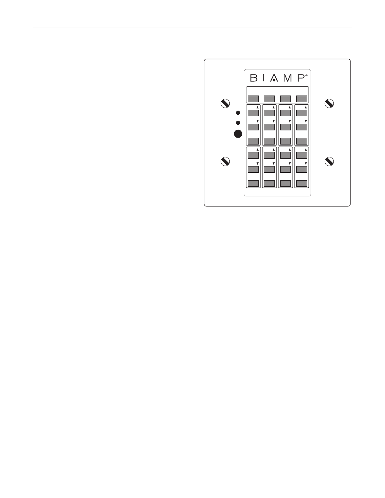
Wall-Mount Panel (WMC) Biamp #909-0076-00: The WMC is a
"hard-wired" control, which receives power from the RT. There are
no batteries to wear out, and it is not easily lost or stolen. The WMC
may be wired up to 2000 feet from the RT, using 2-conductor
shielded cable (not included). See WMC manual for complete
installation instructions. The three screw terminals on the circuit
board ("GND", "IR2", & "IR3") directly correspond to the Remote 1 &
2 terminals on the front panel of the RT. Connect the cable shield to
the "GND" terminal at each end. Use the two conductors to connect
"IR2" to "IR2" and "IR3" to "IR3". Install the front panel in the
mounting box. The WMC has twenty-eight buttons. For
programming purposes, these buttons are given reference numbers
1~28, starting at the bottom and going left-to-right (see diagram at
right). Refer to the table on pg. 3 for the button 'equivalent ASCII
characters. The WMC includes overlay labelling for certain Biamp
products which have pre-defined functions. NOTE: Because the R
allows programmable control functions, custom labelling for the WM
must be provided by the user. When the RT is powered on, power is
delivered to the WMC and the green LED indicator will light. The red
LED indicator on the WMC (and the Data LED indicator on the RT
front panel) will flash whenever a button is pressed. The WMC
includes an infrared detector (below LED indicators), which allows it
to operate as an Infrared Receiver as well. The infrared detector
may be disabled via a circuit board jumper strap (see installation
instructions on pg. 7).
VOL
VOL
MUTE
VOL
VOL
MUTE
SELECT
34
VOL
VOL
MUTE
VOL
VOL
MUTE
VOL
VOL
MUTE
VOL
VOL
MUTE
MASTER
12
VOL
VOL
MUTE
VOL
VOL
MUTE
5678
5
Page 6

CONTROLS
s
GND IR2 IR3
J2
RW5
RW4
RW3
RW2
RW1
COL1
COL2
COL3
COL4
COL5
COL6
COL7
COL8
GND
J1
LED2
LED1
Infrared Transmitter (IR-T) Biamp #909-0066-00: The IR-T is a hand-held control, which transmits
infrared codes unique to Biamp. Therefore, the IR-T should not affect any other infrared controlled
equipment (such as TVs or VCRs). Likewise, other infrared controllers will not provide proper control
of Biamp equipment. The IR-T requires two AAA batteries, which are included with the unit (user
installed). The IR-T has twenty-eight buttons. For programming purposes, these buttons are given
reference numbers 1~28, starting at the bottom and going left-to-right (see diagran at right). Refer to
the table on pg. 3 for the button 'equivalent ASCII characters. The IR-T includes overlay labelling for
certain Biamp products which have pre-defined functions. NOTE: Because the RT allow
programmable control functions, custom labelling for the IR-T must be provided by the user. For best
results, there should be an unobstructed line-of-sight from transmitter to receiver. The IR-T will
operate up to 30 feet from a receiver. When infrared information is transmitted to a receiver, the Data
LED indicator on the RT front panel will flash.
Remote Interface Kit (RIK) Biamp #909-0041-00: The Remote Interface Kit allows the user to
create a customized control panel, using his own momentary push-button switches and enclosure.
It provides up to 40 buttons (12 more than standard remote controls), which are supported by
BIAMP programmable products. The Remote Interface Kit is a tested circuit board, which connects
to the RT in exactly the same way as the WMC. The circuit board is 2.27"W by 2.65"H, with four
mounting holes (2" centers) and #6 mounting hardware. Complete instructions are included with
the Remote Interface Kit.
VOL
VOL
MUTE
VOL
VOL
MUTE
SELECT
34
VOL
VOL
MUTE
VOL
VOL
MUTE
VOL
VOL
MUTE
VOL
VOL
MUTE
MASTER
12
VOL
VOL
MUTE
VOL
VOL
MUTE
5678
6
Page 7

t
a
flange
flange
knock-outs
The wall-mount is a "hard-wired"
Mounting Box
control, which is powered by the
Advantage product it is used with.
There are no batteries to wear out,
and it is not easily lost or stolen.
The wall-mount may be wired up to
2000 feet away, using 2-conductor
shielded cable (not included).
Remove the mounting box from the
front panel. Route the cable through
a "knock-out" hole on the rear of the
mounting box. Install the mounting
box in a wall or panel. The
mounting surface may range from
1/8 inch to 1 inch in thickness.
(3.175mm to 25.4mm)
The mounting cavity must be exactly
4 inches high, 3.6 inches wide, and
at least 2.65" deep.
(101.6mm x 91.44mm x 67.31mm)
(NOTE: The mounting box does no
mount in the same orientation as
standard electrical box.) Insert the
mounting box into the wall or panel,
then tighten the flange screws until
the flanges hold the box securely in
place.
The three screw terminals on the
front panel circuit board of the WallMount ("GND", "IR2", & "IR3")
directly correspond to "Remote"
terminals on the rear panel of the
Advantage product it is controlling.
Connect the cable shield to the
"GND" terminal at each end. Use
the two conductors to connect "IR2"
to "IR2" and "IR3" to "IR3". The
Wall-Mount has an infrared detector
which may be disabled via the circuit
board jumper strap labelled "IR
RECV". The DIP switches labelled
"OPTION SWITCH" remain in the
"OFF" position (down).
Install the front panel in the
mounting box, using the four screws
provided. The green LED indicator
on the face plate will light when
power is delivered to the WallMount. The red LED indicator will
flash when buttons are pushed
(commands transmitted).
Wall-Mount Remote Control Installation
(actual size)
Front Panel Circuit Board
(actual size)
WALL-MOUNT REMOTE
BIAMP SYSTEMS
WALL-MOUNT
PC BOARD
ON
OPTION
SWITCH
ABCD
OFF
GND IR2 IR3
IR RECV
ON
OFF
7
Page 8

APPLICATIONS
PRESENTATION ROOM
RT
27V
~
50/60 Hz
15 watts
class 2 wiring
serial link
cable
(included)
VRAM
27V
~
50/60 Hz
27 watts
class 2 wiring
system setup or control
ADVANTAGE RT
Remote Translator
gnd
IR2
serial port
link port
serial port
link port link expansion
power
data
logic outputs
logic inputs
IR3
remote 1 remote 2
out
in
gnd
IR2
IR3
auxmain aux 2 aux 1
outputs auxiliary inputs
WMC
SELECT
12
34
VOL
VOL
VOL
VOL
VOL
VOL
VOL
VOL
MUTE
MUTE
MUTE
MUTE
VOL
VOL
VOL
VOL
VOL
VOL
VOL
VOL
MUTE
MUTE
MUTE
MUTE
5678
MASTER
input
d. out
channel 8
input
channel 7
d. out
input
channel 6
MUTE
5678
MUTE
MUTE
MASTER
MUTE
input
d. out
channel 5
IR-T
VOL
VOL
VOL
VOL
VOL
VOL
VOL
VOL
d. out
WMC
SELECT
12
VOL
VOL
MUTE
12
VOL
VOL
MUTE
SELECT
VOL
VOL
MUTE
34
VOL
VOL
MUTE
input
channel 4
d. out
input
channel 3
d. out
input
channel 2
34
VOL
VOL
VOL
VOL
VOL
VOL
MUTE
MUTE
MUTE
VOL
VOL
VOL
VOL
VOL
VOL
MUTE
MUTE
MUTE
5678
input
d. out
channel 1
VOL
VOL
MUTE
VOL
VOL
MUTE
MASTER
d. out
SPM723
SPM
27V
~
50/60 Hz
27 watts
class 2 wiring
MSP22e
27V
~
50/60 Hz
12 watts
class 2 wiring
®
723
serial port
link port link
serial port
link port link
logic outputs
logic inputs
zone output main output
logic inputs expansion
RL L R
L R
aux output
input
output
input
channel 1
output
channel 2
to amplifier/speakers
L R
override
sig pres
computer
line
inputs
L
R
MSP22e
L
R
L
R
mute
sig pres
mute
sig pres
1234567override
mic/line 2
COMPACT
DIGITAL AUDIO
mic/line 1mute mute
1
2:50
CD
VHS
VCR
5
101.9
FM
tuner
BIAMP SYSTEMS
Portland, Oregon
an affiliate of
Rauland-Borg Corp.
MADE IN U.S.A.
8
Page 9

WARRANTY
BIAMP SYSTEMS IS PLEASED TO EXTEND THE FOLLOWING 5-YEAR
LIMITED WARRANTY TO THE ORIGINAL PURCHASER OF THE
PROFESSIONAL SOUND EQUIPMENT DESCRIBED IN THIS MANUAL.
BIAMP Systems expressly warrants this product to
be free from defects in material and workmanship
for a period of 5 YEARS from the date of purchase
as a new product from an authorized BIAMP
Systems dealer under the following conditions.
1. In the event the warranted BIAMP Systems
product requires service during the warranty
period, BIAMP Systems will repair or replace, at
its option, defective materials, provided you have
identified yourself as the original purchaser of the
product to any authorized BIAMP Systems Service
Center. Transportation and insurance charges to
and from an authorized Service Center or the
BIAMP Systems factory for warranted products or
components thereof to obtain repairs shall be the
responsibility of the purchaser.
2. This warranty will be VOIDED if the serial
number has been removed or defaced; or if the
product has been subjected to accidental damage,
abuse, rental usage, alterations, or attempted
repair by any person not authorized by BIAMP
Systems to make repairs; or if the product has
been installed contrary to BIAMP Systems's
recommendations.
3. Electro-mechanical fans, electrolytic
capacitors, and the normal wear and tear of
appearance items such as paint, knobs, handles,
and covers are not covered under this warranty.
4. BIAMP SYSTEMS SHALL NOT IN ANY EVENT BE
LIABLE FOR SPECIAL, INCIDENTAL, OR
CONSEQUENTIAL DAMAGES, INCLUDING LOST
PROFITS, LOSS OF USE, PROPERTY DAMAGE,
INJURY TO GOODWILL, OR OTHER ECONOMIC
LOSS OF ANY SORT. EXCEPT AS EXPRESSLY
PROVIDED HEREIN, BIAMP SYSTEMS DISCLAIMS
ALL OTHER LIABILITY TO PURCHASER OR ANY
OTHER PERSONS ARISING OUT OF USE OR
PERFORMANCE OF THE PRODUCT, INCLUDING
LIABILITY FOR NEGLIGENCE OR STRICT LIABILITY
IN TORT.
5. THIS WARRANTY IS IN LIEU OF ALL OTHER
WARRANTIES EXPRESSED OR IMPLIED. BIAMP
SYSTEMS EXPRESSLY DISCLAIMS ALL IMPLIED
WARRANTIES OF MERCHANTABILITY AND
FITNESS FOR A PARTICULAR PURPOSE. THE
REMEDIES SET FORTH HEREIN SHALL BE THE
PURCHASER'S SOLE AND EXCLUSIVE REMEDIES
WITH RESPECT TO ANY DEFECTIVE PRODUCT.
THE AGENTS, EMPLOYEES, DISTRIBUTORS, AND
DEALERS OF BIAMP SYSTEMS ARE NOT
AUTHORIZED TO MODIFY THIS WARRANTY OR TO
MAKE ADDITIONAL WARRANTIES BINDING ON
BIAMP SYSTEMS. ACCORDINGLY, ADDITIONAL
STATEMENTS SUCH AS DEALER
ADVERTISEMENTS OR REPRESENTATIONS DO
NOT CONSTITUTE WARRANTIES BY BIAMP
SYSTEMS.
6. No action for breach of this warranty may be
commenced more than one year after the expiration of
this warranty.
Thank you for purchasing BIAMP SYSTEMS...
AMERICAN SOUND CRAFTSMANSHIP
Biamp Systems
10074 S.W. Arctic Drive
Beaverton, Oregon 97005
(503) 641-7287
http://www.biamp.com
585-9148-00
9
Page 10

Declaration of Conformity
Biamp Systems, Inc., as the manufacturer, hereby declares that the following described product, in our
delivered version, complies with the provisions of the DIRECTIVES except as noted herein. In case of
alteration of the product, not agreed upon or directed by us, this declaration is no longer valid.
Product Model: ADVANTAGE
Product Description: Remote Control Translator
Applicable EC Directives: EMC Directive (89/336/EEC), LVD Directive (73/23/EEC)
Applicable Harmonized Standards: EN55103-1 emissions EN55103-2 immunity EN60065 safety
Special Considerations for Product Environment or Compliance:
This apparatus operates from a removeable external power source at voltages below the levels
encompassed by the LVD. The external power source complies with the applicable requirements of
EN60065. The apparatus itself is outside of the scope of the LVD and presents no hazardous
voltages, as defined in the LVD. For compliance, the apparatus shall be powered only from the
separate CE marked Biamp Systems power source.
Shielded cabling must be used for all connections. Refer to the user’s guide for cabling installation
instructions.
The Technical Report/File is maintained at: Biamp Systems, Inc.
10074 S.W. Arctic Drive
Beaverton, OR USA 97005
phone: (503) 641-7287 fax: (503) 626-0281
e-mail: biamp@biamp.com
Authorized Representative: Steven Hedgepeth
Authorized Representative Signature:
Issued: June, 2000
RT
Page 11

Page 12

Page 13

Page 14

Page 15

 Loading...