

Page 1
RP-L1, RP-L2, & RP-S4
Remote Panels
Instruction Manual
Biamp Systems | 9300 S.W. Gemini Drive | Beaverton, OR | 97008 | USA | +1.503.641.7287 | www.biamp.com
Page 2
RP-L1 & RP-L2
Remote Panels (Level)
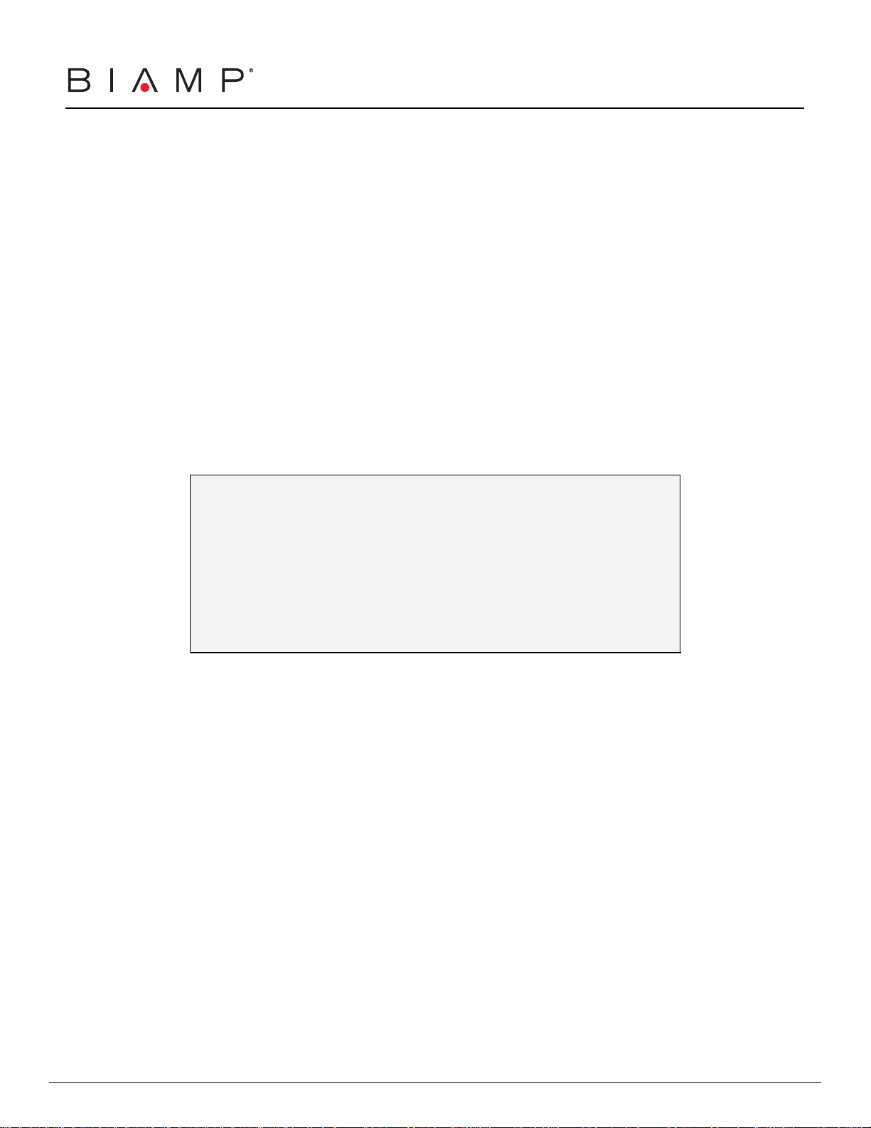
RP-L1
: The RP-L1 is a remote control panel, which consists of a single 25kΩ
linear taper potentiometer mounted on a grey ‘decorator’ style cover plate, with
a single-gang ‘cut-in’ style PVC electrical back-box and a pre-wired pigtail. The
RP-L1 may be used to provide remote control of volume levels as specified for
the following BIAMP products:
products
801 Mic/Line Mixer . . . . . . . . . . Main Output (level)
601 Mic/Line Mixer . . . . . . . . . . Main Output (level)
301 Mic/Line Mixer . . . . . . . . . . Main Output (level)
CMA Series Mixer/Amplifiers . . . . . Main Output (level)
IWA250 In-Wall Mixer/Amplifier . . . . Inputs/Outputs (level)
Voltage Control Box . . . . . . . . . Various Products
Audia (programmable)
Nexia (programmable)
The RP-L1 includes a pre-wired pigtail for ease of installation. This pigtail
consists of three 22-gauge wires, which are color-coded for wiring as follows:
See product manuals for remote control applications and wiring specifics.
Soldered connections with heat-shrink, or properly sized crimp connectors, are
recommended. See last page for back-box installation & block diagrams.
functions
Red . . . . Wiper . . . . . . Control Terminal (C)
White . . . . High (CW) . . . Control Voltage (+10V)
Green . . . Low (CCW) . . . Ground (GND)
RP-L1
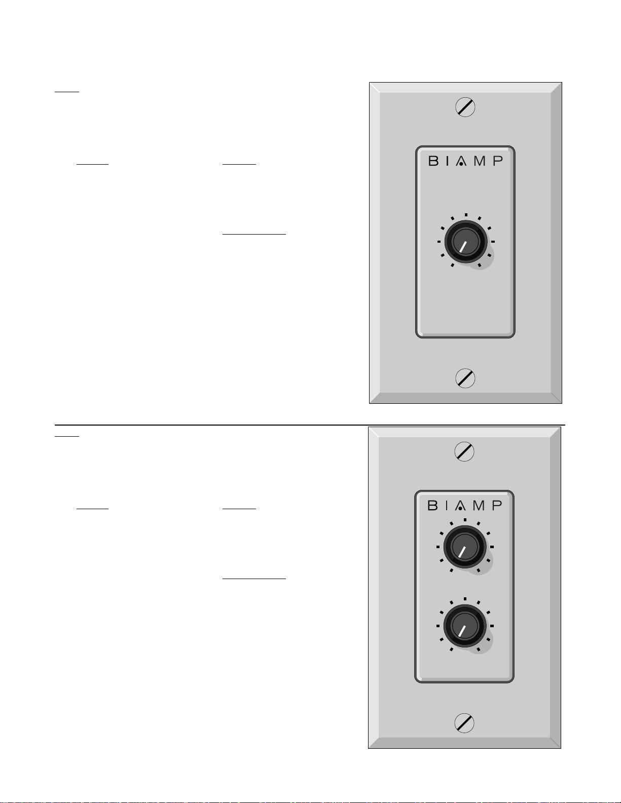
RP-L2
: The RP-L2 is a remote control panel, which consists of two 25kΩ
linear taper potentiometers mounted on a grey ‘decorator’ style cover plate,
with a single-gang ‘cut-in’ style PVC electrical back-box and two pre-wired
pigtails. The RP-L2 may be used to provide remote control of volume levels as
specified for the following BIAMP products:
products
801 Mic/Line Mixer . . . . . . . . . . Main Output (level)
601 Mic/Line Mixer . . . . . . . . . . Main Output (level)
301 Mic/Line Mixer . . . . . . . . . . Main Output (level)
CMA Series Mixer/Amplifiers . . . . . Main Output (level)
IWA250 In-Wall Mixer/Amplifier . . . . Inputs/Outputs (level)
Voltage Control Box . . . . . . . . . Various Products
Audia (programmable)
Nexia (programmable)
The RP-L2 includes two pre-wired pigtails for ease of installation. Each pigtail
consists of three 22-gauge wires, which are color-coded for wiring as follows:
See product manuals for remote control applications and wiring specifics.
Soldered connections with heat-shrink, or properly sized crimp connectors, are
recommended. See last page for back-box installation & block diagrams.
functions
Red . . . . Wiper . . . . . . Control Terminal (C)
White . . . . High (CW) . . . Control Voltage (+10V)
Green . . . Low (CCW) . . . Ground (GND)
RP-L2
Page 3

RP-S4
Remote Panel (Switches)
RP-S4
: The RP-S4 is a remote control panel, which consists of four double-
pole*/double-throw switches mounted on a grey ‘decorator’ style cover plate,
with a single-gang ‘cut-in’ style PVC electrical back-box and four pre-wired
pigtails. The RP-S4 may be used to provide remote control switching as
specified for the following BIAMP products:
products
801 Mic/Line Mixer . . . . . . . . . Main Output (mute)
601 Mic/Line Mixer . . . . . . . . . Main Output (mute)
301 Mic/Line Mixer . . . . . . . . . Main Output (mute)
CMA Series Mixer/Amplifiers . . . . Main Output (mute)
IWA250 In-Wall Mixer/Amplifier . . . Inputs/Outputs (mute)
VSX41 Video Switcher . . . . . . . Inputs 1~4 (selection)
VRAM Automatic Mixer . . . . . . . programmable logic inputs
MSP11 Signal Processor . . . . . . programmable logic inputs
MSP22e Signal Processor . . . . . programmable logic inputs
SPM723 Stereo Preamp/Mixer . . . programmable logic inputs
Voltage Control Box . . . . . . . . Various Products
Audia (programmable)
Nexia (programmable)
Logic Box . . . . . . . . . . . . . Various Products
Audia (programmable)
Nexia (programmable)
The RP-S4 includes four pre-wired pigtails for ease of installation. Each pigtail
consists of three 22-gauge wires, which are color-coded for wiring as follows:
See product manuals for remote control applications and wiring specifics.
Soldered connections with heat-shrink, or properly sized crimp connectors, are
recommended. See last page for back-box installation & block diagrams.
* NOTE: Factory wiring (across both switch poles) provides single-pole
operation. This may be modified if double-pole switch operation is desired.
Momentary Switch Operation:
‘push-on/push-off’ (latching) type of operation. For some applications
(especially when used with the RIK Remote Interface Kit), the switch operation
must be ‘momentary’ (non-latching). The RP-S4 switches each include a small
removable metal jumper strap which provides the latching function. For
momentary switch operation, remove the jumper strap from each switch using
needle-nose pliers. One end of the jumper is under the switch spring, which
may need to be gently moved out of the way. If latching operation should again
become necessary, replace the jumper straps by reversing this process.
functions
White . . . . Up (released - out)
Red . . . . Center (wiper)
Green . . . Down (depressed - in)
From the factory, RP-S4 switches provide a
12
34
RP-S4
jumper
strap
Page 4

Back-Box Installation
y
Remove the back-box from the front panel (controls). Route cables through a
‘knock-out’ hole on the rear of the back-box. Install the back-box in a wall or
panel, in the same orientation as any standard single-gang electrical box.
The mounting surface may be from 1/8” to 1” thick
(3.175mm to 25.4mm)
The mounting cavity must be exactly 3.6” high,
2.25” wide, and at least 2.75” deep
(91.44mm H x 57.15mm W x 69.85mm D)
Insert the back-box into the wall or panel, then tighten the flange screws until
the flanges hold the box securely in place. Wire the remote panel pre-wired
pigtails to the appropriate cable conductors. Soldered connections with heatshrink insulation, or properly sized wire nuts, are recommended. Mount the
front panel to the back-box, being careful not to pinch or short the wires.
NOTE: When an RP-S4 is used with an RIK Remote Interface Kit, the RIK
circuit board will not fit inside the standard single-gang electrical back-box.
Therefore, the RIK must be installed external to the back-box (
to be connected using the wire harnesses provided). An alternative is to utilize
a double-wide electrical back-box, which has the additional space for an RIK.
.
.
et close enough
Back-Box
flange
knock-outs
flange
RP-L1 & RP-L2 Block Diagram
w
GND C +10V
RP-S4 Block Diagram
high (cw)
25k
cwccw
Ω
linear
wiper
low (ccw)
white
red
green
white
red
green
up
wiper
down
up (released)
DPDT
down (depressed)
wiper
white
red
green
585.9131.90A19Mar07
Page 5
 Loading...