

Page 1

ADVANTAGE® RCU
Remote Control Unit
Operation Manual
®
9/2/99
Biamp Systems, 10074 S.W. Arctic Drive, Beaverton, Oregon 97005 U.S.A. (503) 641-7287 http://www.biamp.com
an affiliate of Rauland Borg Corp.
Page 2

blank
Page 3

RCU
TABLE OF CONTENTS
Connections
Controls
Programming
Application
RS-232 Control
Warranty
pg. 2
pg. 3
pg. 4
pg. 9
pg. 10
INTRODUCTION
The ADVANTAGE® RCU Remote Control Unit allows control of certain other
ADVANTAGE
®
programmable products, such as VRAM, MSP, & SPM522D,
via external potentiometers and/or contact-closures. The RCU includes
programming software for assignment of specific functions to the external
controls. Control panels can then be customized to control a variety of level,
muting, source selection, & recall preset functions within a system having
multiple ADVANTAGE
®
products. The RCU carries a five-year warranty.
RCU features include:
♦ RS-232 serial & link ports for communication with products
♦ remote control port accepts up to 23 potentiometers
♦ logic inputs port accepts up to 24 contact-closures
♦ programming software assigns functions to controls
♦ potentiometers provide various level control functions
♦ logic inputs provide muting, source, & preset functions
♦ logic inputs may be used to enable/disable other controls
♦ logic inputs can emulate control buttons & RS-232 commands
♦ covered by Biamp Systems’ five-year warranty
♦ incorporates AES recommended grounding practices
♦
marked and UL / C-UL listed power source
1
Page 4

CONNECTIONS
27V
~
50/60 Hz
12 watts
class 2
wiring
serial port
link port link
BIAMP SYSTEMS
Portland, Oregon
an affiliate of Rauland-Borg Corp.
remote control power logic inputs
AC Power Cord: The power transformer provides 27 Volts AC to
the RCU, and is detachable via a 5-pin DIN connector. The RCU
has two internal ‘self-resetting’ fuses (there are no user
serviceable parts inside the unit). If the internal fuses blow, they
will attempt to re-set after a short period. However, this may be an
indication that the RCU requires service.
Serial Port: This 9-pin Sub-D (male) connector provides an RS232 Serial Port for control of the RCU (and associated products)
via computers or third-party controllers (see RS-232 Control on pg.
10). The Serial Port has the following pin assignments (left-to-right
& top-to-bottom): Pin 1) not used; Pin 2) Receive Data (RxD)
input; Pin 3) Transmit Data (TxD) output; Pin 4) Data Terminal
Ready (DTR) output; Pin 5) Ground; Pin 6) not used; Pin 7)
Request To Send (RTS) output; Pin 8) not used; Pin 9) not
used. PC Control Software and a serial cable are provided for
programming via Windows
®
95 (see Setup on pg. 4). NOTE: The
Serial Port also transmits commands assigned to external
potentiometers & contact-closures (see Remote Control & Logic
Inputs below).
Link Port: This 9-pin Sub-D (female) connector provides a Link
Port for RS-232 control from the RCU to other ADVANTAGE
programmable products (see RS-232 Control on pg. 10). The Link
Port of one device simply connects to the Serial Port of the next
device (and so forth). Link cables are available as an option
(Biamp #909-0057-00). NOTE: All but the final device in a system
should have the Link Switch pressed in (see below). The Link Port
has the following pin assignments (right-to-left & top-to-bottom):
Pin 1) not used; Pin 2) Transmit Data (TxD) output; Pin 3)
Receive Data (RxD) input; Pin 4) not used; Pin 5) Ground;
Pin 6) Data Set Ready (DSR) output; Pin 7) not used; Pin 8)
Clear To Send (CTS) output; Pin 9) not used. NOTE: The Link
Port also transmits commands assigned to external potentiometer
& contact-closures ( see Remote Control & Logic Inputs below).
RCU
Remote Control: This 25-pin Sub-D (female) connector allows
connection of up to 23 potentiometers (on pins 1~23 respectively),
with a common control voltage (+5 Volts DC on pin 24), and a
common ground (on pin 25). Potentiometers should be between
5k ohms and 50k ohms in value, with a linear taper (see Controls
on next page). Potentiometers are wired with high to +5 Volts (pin
24), low to ground (pin 25), & wiper to the desired control terminal
(pins 1~23). Each potentiometer may be programmed to control a
specific function on a specific product (see Setup on pg. 4). These
functions typically include various level adjustments.
Logic Inputs: This 25-pin Sub-D (female) connector allows
connection of up to 24 contact-closures (on pins 1~24 respectively)
with a common ground (on pin 25). Contact-closures may be
switches, relays, or logic outputs from other devices (see Controls
on next page). Each logic input may be programmed to control a
specific function on a specific product (see Setup on pg. 4).
These functions typically include muting, source selection, & preset
selection. However, logic inputs may also be programmed to
enable/disable potentiometers or other logic inputs, as well as to
transmit custom ASCII characters commands to other products.
®
Power Indicator: When the power transformer is plugged in, and
AC power is applied to the RCU, the Power indicator remains lit.
Link Switch: The Link Switch is used when connecting multiple
devices in a ‘Link Port to Serial Port’ configuration (see Link Port
above). From the factory, the Link Switch is released (out). When
connecting multiple devices, the Link Switch must be depressed
(in) on all devices except the final device in the system (the device
with no Link Port connection).
2
Page 5
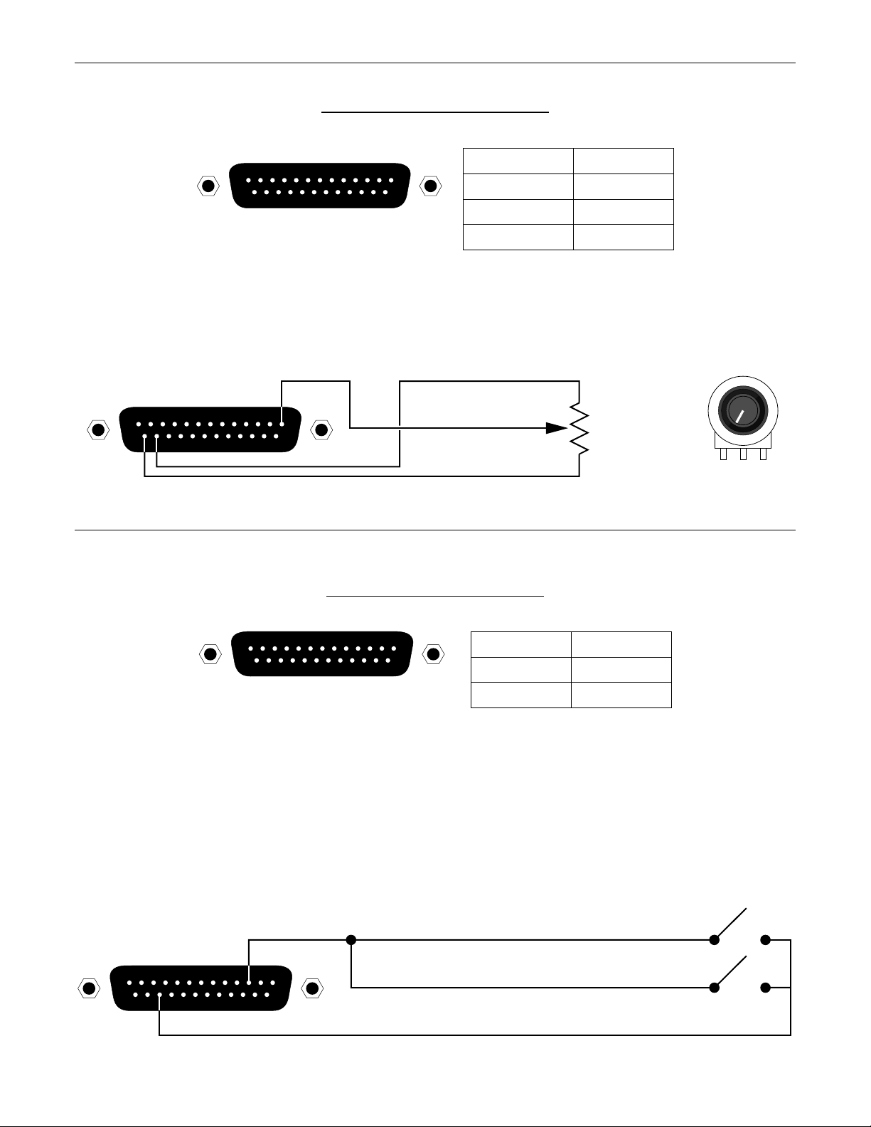
CONTROLS
REMOTE CONTROL / POTENTIOMETERS
13 1
25 14
remote control
remote control pin numbers
pots #1~23
+5 Volts
ground
pin #1~23
pin #24
pin #25
Rotary or slide potentiometers may be used with the RCU. Potentiometers should be between 5k ohms and 50k ohms in value, with a
linear taper. Potentiometers are wired to the RCU Remote Control port with the ‘high’ side of the potentiometer to +5 Volts (pin 24), the
‘low’ side of the potentiometer to ground (pin 25), & the ‘wiper’ of the potentiometer to the desired control terminal (pins 1~23).
potentiometer wiring
wiperpot #1
high (cw)
low (ccw)
5kΩ∼50kΩ
linear taper
w
cwccw
gnd pot +5V
+5 Volts
13 1
25 14
ground
LOGIC INPUTS / CONTACT-CLOSURES
13 1
25 14
logic inputs
logic inputs pin numbers
logic #1~24
ground
pin #1~24
pin #25
When nothing is connected to a Logic Input, an internal pull-up resistor keeps it at a ‘high’ idle state (+5.0 VDC). The Logic Input is
activated when its input goes ‘low’ (less than +0.8 VDC), and is de-activated when its input goes ‘high’ (greater than +2.4 VDC). A Logic
Input is controlled in one of three ways: 1) Use a switch, relay, or other contact-closure (such as from a third-party controller) to short the
Logic Input to ground. 2) Use an NPN style ‘open-collector’ logic output from an external to short the Logic Input to ground. 3) Use an
active TTL output driver circuit (such as from a third-party controller) to actively drive the Logic Input to a ‘high’ or ‘low’ state. Multiple
contact-closures or ‘open-collector’ logic outputs may be wired in parallel to a single Logic Input (see diagram below). Logic Outputs and
contact-closures should be rated for at least 5 Volts / 1mA operation. Low-current / dry-contact closures are recommended for reliability.
Active output driver circuits should not exceed a signal range of 0~5 Volts DC, and should have a minimum pulse width of 100 milliseconds. Logic Input impedances are approximately 10k ohms.
multiple switches to single Logic Input
13 1
25 14
3
Page 6
SETUP
RCU parameters are all adjustable using the BiampWin PC Control Software and serial cable provided with the unit. The BiampWin
software provides programs for various ADVANTAGE® products, including the RCU. The RCU program includes several control screens,
which are described on the following pages. Once the software is started (and Comm Port Configuration is set), the control screens are
accessed via the drop-down menus at the top of the opening screen. The Main screen appears whenever an RCU file is opened. Pot
Definition, Logic Input Definition, & Configuration Options screens are then available from the Configure RCU menu. The File menu
provides functions such as open, close, save, etc. The Settings menu recalls the Comm Port Configuration screen. The Window menu
arranges the active product screens. The Help menu explains the available adjustments. To install PC Control Software: Insert BiampWin
Disk 1 into Drive A:, select ‘Run’ from the Start’ menu, and enter A:\SETUP. System Requirements: Windows® 95/98/NT, with 16M RAM
and 5M of available hard disk space (serial port required for ‘on-line’ operation).
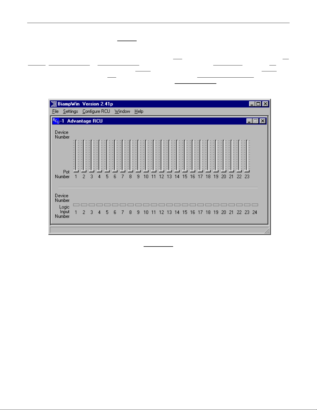
MAIN SCREEN
4
Page 7

SETUP
MAIN SCREEN
The Main Screen allows you to view the current status of all 23 potentiometers (‘pots’) and all 24 logic inputs.
Pots: Each of the 23 pots is represented on the Main Screen by a linear fader which is continuously updated to indicate the current pot
setting and to indicate whether the pot is currently enabled or disabled. When a pot is disabled, the fader knob is grayed-out slightly and a
small ‘X’ appears in the knob. The fader knob position is updated whenever the pot is adjusted, even if the pot is disabled. Since the
faders always reflect the current settings of the physical pots which are connected to the RCU, any attempts to use the mouse to move
fader knobs on the Main Screen will have no effect. Each pot may be programmed to perform a specific control function for a specific
product. The programming process is performed using the Pot Definition Screen. The Pot Definition Screen may be activated by selecting
it from the “Configure RCU” menu or by double-clicking on any fader. When a definition has been established for a particular pot, an icon
and device number will appear above the fader on the Main Screen. The icon and device number indicate which device the pot is
programmed to control. When the mouse pointer is positioned over the fader, a pop-up ‘hint’ appears which provides a detailed description
of the function which the pot is programmed to perform.
Logic Inputs: Each of the 24 logic inputs is represented on the Main Screen by an ‘LED’ indicator which is continuously updated to indicate
the current on/off status and to indicate whether the logic input is currently enabled or disabled. When a logic input is disabled, the LED
indicator is grayed-out slightly and a small ‘X’ appears in the LED. The LED indicator is updated whenever the logic input status is
changed, even if the logic input is disabled. When the LED indicator is ‘on’ (red), the switch contact is closed (the logic input is shorted to
ground through the contact-closure). When the LED indicator is ‘off’, the switch contact is open. Each logic input may be programmed to
perform a specific control function for a specific product. Logic inputs may also be programmed to disable or enable other logic inputs or
pots. A logic input may also be programmed to output a user-defined ASCII character string. The programming process is performed
using the Logic Input Definition Screen. The Logic Input Definition Screen may be activated by selecting it from the “Configure RCU” menu
or by double-clicking on any logic input LED indicator. When a definition has been established for a logic input, an icon and, in most cases,
a device number will appear above the LED indicator on the Main Screen. The icon and device number indicate which device the logic
input is programmed to control. When the mouse pointer is positioned over the LED indicator, a pop-up ‘hint’ appears which provides a
detailed description of the function which the logic input is programmed to perform. The last six logic inputs (logic inputs 19 through 24)
may be programmed to operate in ‘binary mode’ using the Configuration Options Screen. In this mode, whenever one of these six logic
inputs changes state, the binary on/off status of all six logic inputs determines what function will be performed. There are sixty-four
possible binary on/off combinations of these six logic inputs. Each of the sixty-four combinations may have a logic input definition assigned
to it. These logic input definitions are created using the Logic Input Definition Screen.
5
Page 8

SETUP
POT DEFINITION SCREEN
Up to 23 potentiometers may be connected to the Remote Control input port of the RCU. Each pot may be programmed to perform a
specific control function for a specific product. The programming process is performed using the Pot Definition Screen. Each product that
is linked to the RCU must have a unique device number. When creating a pot definition, you must specify the device number of the
product which that pot will be controlling. You must also specify the model of the product (VRAM, MSP22e, etc.). Once you have specified
the model, a list of available operations appears in the “Operation” list box. The list of operations changes depending upon which model is
selected. Most operations also allow you to specify a minimum value and a maximum value for the pot. If you do not override the default
values shown, the entire range of pot travel will correspond directly to the entire volume range that is possible for the specified operation.
By specifying a Min Value and/or a Max Value, you may restrict the range of volume levels for the pot. For example, each volum e control
on an VRAM has 32 settings (or ‘steps’), ranging from a minimum value of 0 to a maximum value of 31. If you set Min Value to 3 and Max
Value to 28, then the fully counter-clockwise position of the pot will correspond to volume step 3 and the fully clockwise position of the pot
will correspond to volume step 28. A “Pot Simulation” fader appears on the Pot Definition Screen. This fader provides a convenient
method to test the pot definition as it is being created. Using the mouse to move the fader knob simulates the movement of the actual
potentiometer which is being defined. During an on-line session, moving the Pot Simulation fader knob will cause BiampWin to transmit
the appropriate character string commands to the specified product. NOTE: RS-232 level commands from other sources, including the
Pot Simulation fader, may conflict with actual pot settings. However, these conflicts are resolved as soon as the pot is again manipulated.
If the specified model is either a VRAM/VRAMeq or an SPM522D, then a “Use Logic Input for Muting” checkbox appears. With these
models, if you wish to use a pot as a volume control AND use a logic input to perform muting functions for the pot, you should select the
“Use Logic Input for Muting” checkbox and an appropriate logic input definition will automatically be created for you. This links the
operation of the logic input and the pot, allowing for cooperative control. NOTE: “Use Logic Input for Muting” is defined to mute when a
switch closes, and un-mute when the switch opens. Therefore, a ‘latching’ switch will maintain the selected muting status (muted or unmuted), whereas a ‘momentary’ switch will temporarily mute (only while the switch is held closed). Other forms of muting are available,
which behave differently when used in conjunction with a pot (see Logic Input Definition Screen on next page). However, these forms of
muting may cause conflicts, such as un-muting when the pot is manipulated, and un-muting to levels established by means other than the
pot (RS-232 commands, Pot Simulation fader, product software, etc.). In some cases, these forms of muting may actually be considered
desirable. When a definition has been established for a particular pot, an icon and device number will appear above the fader on the Main
Screen. The icon and device number indicate which device the pot is programmed to control. When the mouse pointer is positioned over
the fader, a pop-up ‘hint’ appears which provides a detailed description of the function which the pot is programmed to perform.
Connecting Pots to the RCU: The RCU is designed to be used with linear taper pots. The resistance value of the pots can be as low as
5K ohms or as high as 50K ohms. Pins 1 through 23 of the “Remote Control” connector on the RCU are for pot inputs. Pin 24 is a
reference voltage output (which is approximately +5 volts DC), and pin 25 is ground. The ‘high’ (clockwise) side of all pots should be
connected to the reference voltage output on pin 24 of the remote control connector. The ‘low’ (counter-clockwise) side of all pots should
be connected to ground on pin 25 of the remote control connector. The wiper of each pot should be connected to the pin corresponding to
the pot number (1 through 23). In some cases, the wiper could be connected to more than one pin if you want to control more than one
volume level with the same pot (to simulate a ‘ganged’ pot).
6
Page 9

SETUP
LOGIC INPUT DEFINITION SCREEN
Up to 24 contact-closures may be connected to the Logic Inputs port of the RCU. Contact-closures may be switches, relays, or logic
outputs from other devices. Each logic input may be programmed to perform a specific control function for a specific product. This
programming process is performed using the “Advantage Device Control Function” section of the Logic Input Definition Screen. Each
product that is linked to the RCU must have a unique device number. When creating a logic input definition, you must specify the device
number of the product which that logic input will be controlling. You must also specify the model of the product (VRAM, MSP22e, etc.).
Once you have specified the model, a list of available operations appears in the “Operation” list box. The list of operations changes
depending upon which model is selected. When a definition has been established for a particular logic input, an icon and device number
will appear above the ‘LED’ indicator on the Main Screen. The icon and device number indicate which device the logic input is
programmed to control. When the mouse pointer is positioned over the LED indicator, a pop-up ‘hint’ appears which provides a detailed
description of the function which the logic input is programmed to perform. In addition to specifying which actions occur when a contact
closes, you also may specify which actions occur when a contact opens. Normally, each of the 24 logic inputs acts independently of the
others. Using the Configuration Options Screen, the six highest logic inputs (19 through 24) may be programmed to operate in ‘binary’
mode. When in binary mode, a logic input definition may be created for each of the 64 possible binary on/off combinations of logic inputs
19 through 24. Logic inputs may also be programmed to enable/disable other logic inputs or pots, or to transmit a user-defined ASCII
character string (this programming does NOT require a device number or product model be specified). Individual checkboxes are provided
for disabling or enabling each of the other logic inputs, as well as for disabling or enabling each of the 23 pots. The Logic Input Definition
Screen prevents you from disabling or enabling the logic input which is currently being defined. You should be careful not to create a
situation where one or more pots or logic inputs have been disabled with no way of becoming re-enabled again (if you find yourself in such
a situation, a quick way of re-enabling all pots and logic inputs can be found on the Configuration Options Screen). When programming a
logic input to transmit a user-defined ASCII character string, you may define a string of up to 14 characters. This string may consist of any
combination of ASCII characters except for the NUL character (whose decimal value is zero). ASCII character strings may be used to write
advanced product/function commands which are not available from the ‘Options’ list box (see Computer Control Manual for the product to
be controlled). Single ASCII characters may also be used to emulate remote control buttons, which are then programmable on an
individual product basis, using this same BiampWin software (see RS-232 Control on pg. 10).
7
Page 10

SETUP
CONFIGURATION OPTIONS SCREEN
The Configuration Options screen displays information about the RCU which is currently active, and allows changes to certain "global"
configuration options associated with that device. The Firmware Version field displays the version date of the firmware (software) which
resides inside the currently active device. This date is the "release" date of the firmware, not the date that the device was manufactured.
The firmware version may not be edited. Device Number allows a device number (0~63) to be assigned to the currently active RCU.
NOTE: When multiple ADVANTAGE
®
programmable products are to be linked (via RS-232) for system-wide communications, each
product must first be assigned a unique Device Number. Each RCU may be assigned a name by using the Device Name field. This name
is stored in the non-volatile memory of the device. If a name is assigned, it will appear in the title bar of the PC software's Main Screen for
that RCU. Each RCU may be assigned a device number from 0 to 63. This allows multiple RCUs (or other ADVANTAGE
®
programmable
products) to be individually controlled when linked together. Unique device numbers must be assigned to each device before the devices
are linked together. The last six logic inputs (logic inputs 19 through 24) may be configured to operate in "binary mode." In this mode,
whenever one of the six logic inputs changes state, the binary on/off status of all six logic inputs determines what function will be
performed. There are sixty-four possible binary on/off combinations of these six logic inputs. Each of the sixty-four combinations may
have a logic input definition assigned to it. These logic input definitions are created using the Logic Input Definition Screen (see previous
page). When creating logic input definitions which disable other logic inputs or pots, it is possible to find yourself in a situation where one
or more logic inputs or pots have been disabled, with no way of re-enabling them. Clicking on the "Enable All Pots and Logic Inputs" button
causes all pots and logic inputs to immediately be re-enabled.
8
Page 11

APPLICATIONS
RCU Remote Control of VRAM
Level Control Panel ('manual' mode)
CH-1 CH-2 CH-3 CH-4 CH-5 CH-6 CH-7 CH-8 AUX 1 AUX 2 MASTER
Pots 1~22 defined to adjust all
VRAM input/output levels
Preset Selection Panel ('auto' mode)
Logic Input #17 defined to select between
(enable/disable) pots 1~22 (manual mode)
& logic inputs 1~16 (auto mode - presets)
MAIN
OUTPUT
AUX
OUTPUT
PRESETS
auto / manual
12345678910111213141516keylock
Logic Inputs 1~16 defined to
recall VRAM presets 1~16
RCU
27V
50/60 Hz
12 watts
class 2
wiring
~
serial port
link port link
BIAMP SYSTEMS
Portland, Oregon
an affiliate of Rauland-Borg Corp.
remote control power logic inputs
CD player - aux 1
RCU
COMPACT
1
2:50
DIGITAL AUDIO
microphones - channels 1~8
cassette - aux 2
VRAM
27V
50/60 Hz
27 watts
class 2 wiring
serial port
~
link port link expansion
Main Output Aux Output
logic outputs
logic inputs
out
in
auxmain aux 2 aux 1
outputs auxiliary inputs
input
channel 8
d. out
input
channel 7
d. out
input
channel 6
d. out
input
channel 5
d. out
input
channel 4
d. out
input
channel 3
d. out
input
channel 2
d. out
input
channel 1
d. out
9
Page 12

RS-232 CONTROL
The RCU has an RS-232 Serial Port, which allows it to be controlled by a computer, and a Link Port, which allows the RCU itself to transmit
computer control commands to other ADVANTAGE
®
programmable products (see Connections on pg. 2). In addition to the BiampWin PC
Control Software, the RCU offers two other methods of computer control.
Control Button Emulation: This method allows the RCU (or computer) to imitate the operation of infrared or wall-mount control panels.
Although the RCU does not accept these types of controls itself, it can still receive and transmit ASCII characters (via RS-232) which
emulate the remote control buttons supported by other ADVANTAGE
on ADVANTAGE
®
programmable products have equivalent ASCII characters permanently assigned to them (see table below). Therefore,
®
programmable products. From the factory, remote control buttons
actions can be assigned to remote control buttons during the programming of these products. Then, using this method, the RCU (or
computer) can then output (to the other products) ASCII characters which are equivalent to the commands generated by remote control
buttons. Control Button Emulation allows these other products to utilize up to forty button definitions (unlike standard remote controls,
which have only twenty-eight buttons). For more information, see the manual or BiampWin program for the products to be controlled.
Advanced Computer Control: This method provides advanced commands, which allow the RCU (or computer) to retrieve or edit various
settings from other ADVANTAGE
computer may designate up to
®
programmable products. The computer may also emulate control buttons. Using this method, the
sixty-four devices, and may also provide ‘real-time’ display of various settings.
This manual only describes the Control Button Emulation method of computer control. For complete details about using the RCU with a
computer, including Advanced Computer Control, contact Biamp Systems for the manual "Computer Control
of ADVANTAGE® RCU".
Each control button on an infrared transmitter or wall-mount control panel corresponds to one character in the standard ASCII character
set. The character equivalents are summarized in the following table. This table includes all forty possible buttons, their button numbers,
and their ASCII code equivalents. Their button definitions are defined during programming of the product to be controlled.
button 01 B programmable by product button 15 P programmabl e by product button 29 ^ programm abl e by product
button 02 C programmable by product button 16 Q programmable by product button 30 _ programmable by product
button 03 D programmable by product button 17 R programmable by product button 31 ' programmable by product
button 04 E programmable by product button 18 S programmabl e by product button 32 b programmable by product
button 05 F programmable by product button 19 T programmable by product button 33 c programmable by product
button 06 G programmable by product button 20 U programmable by product button 34 d program mable by product
button 07 H programmable by product button 21 V programmable by product button 35 e programm abl e by product
button 08 I programmable by product button 22 W program mable by product but ton 36 f programmable by produc t
button 09 J programmable by product button 23 X programmable by product butt on 37 g programmable by product
button 10 K programmable by product button 24 Y programmabl e by product button 38 h programmable by product
button 11 L programmable by product butt on 25 Z programmable by product button 39 i programmable by product
button 12 M program mable by product but ton 26 [ programmable by produc t button 40 j programmable by product
button 13 N programmable by product button 27 \ programmable by product
button 14 O programmable by product button 28 ] programmable by product
The RCU (or computer) can initiate any functions or actions that a standard control can, by simply transmitting the equivalent control button
ASCII character. When interfacing the RCU to a computer, the computer must be aware that the RCU will ‘echo’ all characters it receives
via the Serial Port Transmit Data (TXD) output signal. NOTE: The Serial Port will also transmit commands which have been assigned to
the RCU Remote Control pots & Logic Input switches (see Setup on pg. 4).
10
Page 13

RS-232 CONTROL
Serial Port: The 9-pin Sub-D (male) connector provides the RS-232 compatible serial interface signals used for computer (or third-party)
control of the RCU. The RCU Serial Port transmits serial data on pin 3 (TxD), receives serial data on pin 2 (RxD), and provides a ground
on Pin 5. The Data Terminal Ready (DTR) & Request To Send (RTS) output signals are connected to the +12 Volt power supply (through
a resistor) and are always asserted when the RCU power is on. NOTE: The Serial Port will also transmit commands which have been
assigned to the RCU Remote Control pots & Logic Input switches (see Setup on pg. 4).
54321
9876
serial port
pin #1 = not used
pin #2 = Receive Data (RxD) input
pin #3 = Transmit Data (TxD) output
pin #4 = Data Terminal Ready (DTR) output
pin #5 = ground
pin #6 = not used
pin #7 = Request To Send (RTS) output
pin #8 = not used
pin #9 = not used
The RCU only requires receive data (pin 2), transmit data (pin 3), and signal ground (pin 5) to be connected for successful data
communications (see cable diagram below). However, the PC may require that signals be present on the data set ready, clear to send, or
carrier detect inputs, as well as the receive data, transmit data, and signal ground pins. Success or failure depends entirely on the actual
computer hardware and software being used. When trying to solve an interfacing problem, the most important thing to remember is that an
output of one device should connect to one or more inputs of the other device, and that two outputs should never be connected together.
Also, keep in mind that the RS-232 specification calls for the cable length to be no greater than 50 feet (although it is not unusual to be
able to operate over distances of 150 to 250 feet), and the connectors must be of the appropriate gender (male or female) to mate
properly. For best results, a shielded cable should be used, with the shield connected to chassis ground. Undesirable ground loops may
occur when the RCU is connected to a PC (if the system grounding is not carefully designed). For best performance, the PC ground and
the chassis ground of the RCU should be at the same potential, and the PC should get AC power from the same source as the RCU (and
any other audio equipment which is connected to the RCU). Since most lap-top computers are isolated from earth ground, this should
rarely pose a problem.
Serial Port Data Co m mu n ic at io n s Pa ram e te rs: The RCU communicates through the Serial Port at the factory selected rate of 9600 bits
per second, with 8 data bits, 1 stop bit, and no parity. The RCU utilizes a subset of the standard 7-bit ASCII character set. The eighth data
bit of each character (the most significant bit) should always be 0. The computer should not echo the characters it receives. The computer
should not be set for either hardware (DTR) or software (XON/XOFF) flow control. The baud rate may be changed to either 2400, 19200,
or 38400 bits per second by means of the software (see Setup on pg. 4).
Link Port Connections: The 9-pin Sub-D (female) connector provides the RS-232 compatible serial interface signals used for RCU
control of other ADVANTAGE
®
programmable products within a system. The Link Port of one device simply connects to the Serial Port of
the next device, and so forth (see diagram below). Link cables are available as an option (Biamp #909-0057-00). The Data Set Ready
(DSR) & Clear To Send (CTS) output signals are connected to the +12 Volt power supply (through a resistor) and are always asserted
when the RCU power is on. NOTE: All but the final device in a system should have its ‘Link’ switch pressed in (see Connections on pg. 2).
The Link Port transmits commands assigned to the Remote Control pots & Logic Inputs, and will ‘echo’ commands received at the Serial
Port (from computers or third-party controllers).
PC
CD
RxD
TxD
DTR
gnd
DSR
RTS
CTS
RI
male female
12345
6789
link port
serial port
1
2
3
4
5
6
7
8
9
Serial Cable
1
2
3
4
5
6
7
8
9
(shield)
pin #1 = not used
pin #2 = Transmit Data (TxD) output
pin #3 = Receive Data (RxD) input
pin #4 = not used
pin #5 = ground
serial port
1
2
3
4
5
6
7
8
9
female male
RCU
n/a
1
RxD
2
TxD
3
DTR
4
gnd
5
n/a
6
RTS
7
n/a
8
n/a
9
RCU
n/a
TxD
RxD
n/a
gnd
DSR
n/a
CTS
n/a
female male
pin #6 = Data Set Ready (DSR) output
pin #7 = not used
pin #8 = Clear To Send (CTS) output
pin #9 = not used
1
2
3
4
5
6
7
8
9
Link Cable
(shield)
female male
link port
1
2
3
4
5
6
7
8
9
serial port
1
2
3
4
5
6
7
8
9
unit 2
n/a
1
RxD
2
TxD
3
DTR
4
gnd
5
n/a
6
RTS
7
n/a
8
n/a
9
11
Page 14

WARRANTY
BIAMP SYSTEMS IS PLEASED TO EXTEND THE FOLLOWING 5-YEAR
LIMITED W A RRANTY TO THE ORIGINAL PURCHASER OF THE
PROFESSIONAL SOUND EQUIPMENT DESCRIBED IN THIS MANUAL.
BIAMP Systems expressly warrants this product to be
free from defects in material and workmanship for a
period of 5 YEARS from the date of purchase as a
new product from an authorized BIAMP Systems
dealer under the following conditions.
1. In the event the warranted BIAMP Systems product
requires service during the warranty period, BIAMP
Systems will repair or replace, at its option, defective
materials, provided you have identified yourself as the
original purchaser of the product to any authorized
BIAMP Systems Service Center. Transportation and
insurance charges to and from an authorized Service
Center or the BIAMP Systems factory for warranted
products or components thereof to obtain repairs shall
be the responsibility of the purchaser.
2. This warranty will be VOIDED if the serial number
has been removed or defaced; or if the product has
been subjected to accidental damage, abuse, rental
usage, alterations, or attempted repair by any person
not authorized by BIAMP Systems to make repairs; or
if the product has been installed contrary to BIAMP
Systems's recommendations.
3. Electro-mechanical fans, electrolytic capacitors,
and the normal wear and tear of appearance items
such as paint, knobs, handles, and covers are not
covered under this warranty.
4. BIAMP SYSTEMS SHALL NOT IN ANY EVENT BE
LIABLE FOR SPECIAL, INCIDENTAL, OR
CONSEQUENTIAL DAMAGES, INCLUDING LOST
PROFITS, LOSS OF USE, PROPERTY DAM AGE, IN JURY
TO GOODWILL, OR OTHER ECONOMIC LOSS OF ANY
SORT. EXCEPT AS EXPRESSLY PROVIDED HEREIN,
BIAMP SYSTEMS DISCLAIMS ALL OTHER L IABILITY TO
PURCHASER OR ANY OTHER PERSONS ARISING OUT
OF USE OR PERFORMANCE OF THE PRODUCT,
INCLUDING LIABILITY FOR NEGLIGENCE OR STRICT
LIABILITY IN TORT.
5. THIS WARRANTY IS IN LIEU OF ALL OTHER
WARRANTIES EXPRESSED OR IMPLIED. BIAMP
SYSTEMS EXPRESSLY DISCLAIMS ALL IMPLIED
WARRANTIES OF MERCHANTABILITY AND FITNESS
FOR A PARTICULAR PURPOSE. THE REMEDIES SET
FORTH HEREIN SHALL BE THE PURCHASER'S SOLE
AND EXCLUSIVE REMEDIES WITH RESPECT TO ANY
DEFECTIVE PRODUCT. THE AGENTS, EMPLOYEES,
DISTRIBUTORS, AND DEALERS OF BIAMP SYSTEMS
ARE NOT AUTHORIZED TO MODIFY THIS WARRANTY
OR TO MAKE ADDITIONAL WARRANTIES BINDING ON
BIAMP SYSTEMS. ACCORDINGLY, ADDITIONAL
STATEMENTS SUCH AS DEALER ADVERTISEMENTS
OR REPRESENTATIONS DO NOT CONSTITUTE
WARRANTIES BY BIAMP SYSTEMS.
6. No action for breach of this warranty may be
commenced more than one year after the expiration of this
warranty.
Thank you for purchasing BIAMP SYSTEMS...
AMERICAN SOUND CRAFTSMANSHIP
Biamp Systems
10074 S.W. Arctic Drive
Beaverton, Oregon 97005
(503) 641-7287
http://www.biamp.com
585.9143.00
Page 15

Page 16

Page 17

Page 18

 Loading...