

Page 1
®
ACCESSORY
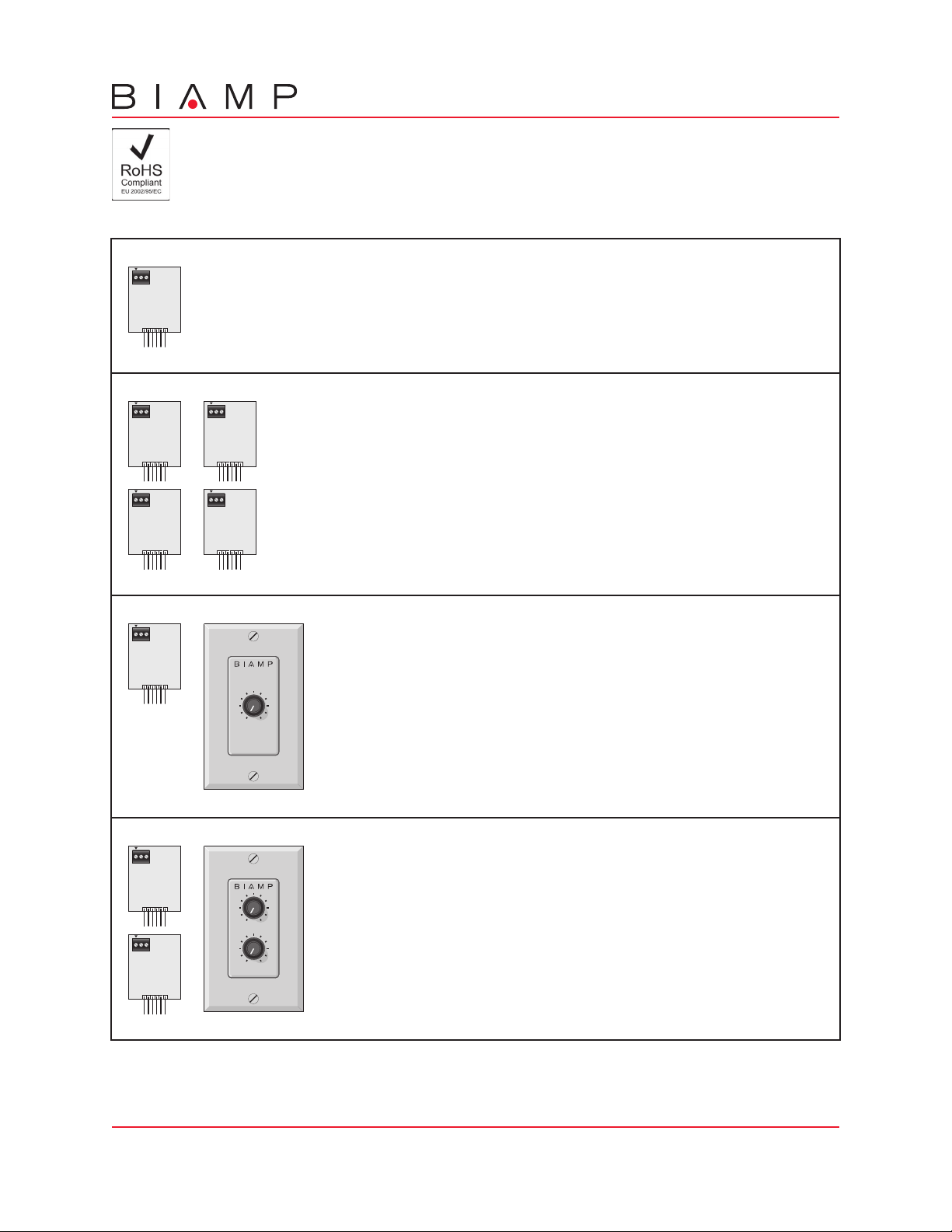
IWA250 VCA Packages
Remote Control Options
C +10V
VCA
card
C +10V
VCA
card
C +10V
VCA
card
C +10V
VCA
card
VCA-1
A single VCA Card for remote level control of an individual input or output. The VCA Card
installs onto the IWA250 circuit board, and requires an external potentiometer to control.
C +10V
VCA-4
VCA
card
C +10V
VCA
card
A package of four VCA Cards for remote level control of various inputs and/or
outputs. The VCA Cards install onto the IWA250 circuit board, and require
external potentiometers to control. A single potentiometer may be wired to
multiple VCA Cards for combined control of a group of signals.
RCP-1
A package including a single VCA Card and an RP-L1 remote panel.
The VCA Card installs onto the IWA250 circuit board. The RP-L1 remote
panel provides a 25k ohm linear taper potentiometer mounted on a grey
'decorator' style cover plate, with a single-gang 'cut-in' style PVC
RP-L1
electrical back-box and pre-wired pigtail.
C +10V
RCP-2
VCA
card
C +10V
VCA
card
RP-L2
Biamp Systems, 10074 S.W. Arctic Drive, Beaverton, Oregon 97005 U.S.A. (503) 641-7287 www.biamp.com
A package including two VCA Cards and an RP-L2 remote panel. The
VCA Cards install onto the IWA250 circuit board. The RP-L2 remote
panel provides two 25k ohm linear taper potentiometers mounted on a
grey 'decorator' style cover plate, with a single-gang 'cut-in' style PVC
electrical back-box and pre-wired pigtails.
Page 2
®
C +10V
VCA
card
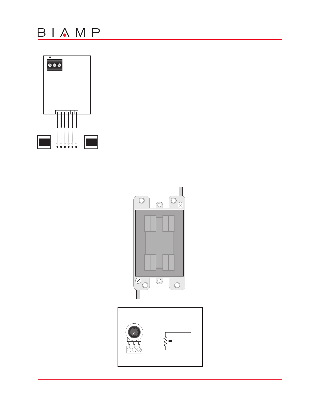
CH 1
+12V
+10V
GND
-12V
OUT
IN
mixer circuit board channel
IWA250 VCA Card Installation
To install VCA Cards, first remove the jumper wires (between OUT and IN) on the
respective channels/outputs of the mixer circuit board. Then install the two plastic
support/guides (provided with each VCA Card) into the holes provided on the
respective channels/outputs of the mixer circuit board (support/guides must be
properly oriented to accept VCA Card). Once the support/guides are in place, slide
the VCA Cards into the support/guides, making sure all pins on the VCA card slide
fully into the corresponding holes in the mixer circuit board.
Once the VCA Cards have been installed, remote controls (such as RP-L1 & RP-L2)
may be wired up to 2000 feet away, using 2-conductor shielded cable. Controls may
be any 5k~50k ohm linear taper potentiometer and/or switch to provide adjustment
and/or muting of the level. Potentiometers are wired with high-side to "+10V", lowside to "
"C" terminal on multiple VCA Cards, allowing control of a group of signals from a
single potentiometer. Switches simply connect (or disconnect) "+10V" to "C", and
do not require a ground ('
may be used, with the switch in line with either the "C" or "+10V" connection.
NOTE: When a VCA Card is installed, but no control is connected, signal will not
pass. To avoid this circumstance, a jumper wire may be temporarily connected
between "+10V" and "C". Additionally, if VCA Cards are removed, jumper wires
must be re-installed between OUT and IN on the respective channels/outputs of the
mixer circuit board, before signal can pass.
", and wiper to "C". The wiper of one potentiometer may be wired to the
') connection. A combination of potentiometer and switch
flange
Single-Gang Cut-In PVC
Electrical Back-Box for
RP-L1 & RP-L2
w
GND C +10V
knock-outs
flange
RP-L1 & RP-L2 Block Diagram
25kΩ
cwccw
linear
high (cw)
wiper
low (ccw)
Mounting Surface may be from 1/8" to 1" thick.
(3.175mm to 25.4mm)
Mounting Cavity must be exactly 3.6" high,
2.25" wide, and at least 2.75" deep.
(91.44mm H x 57.15mm W x 69.85mm D)
white
red
green
Biamp Systems, 10074 S.W. Arctic Drive, Beaverton, Oregon 97005 U.S.A. (503) 641-7287 www.biamp.com
18Dec06
 Loading...