

Page 1
support@biamp.com
www.biamp.com
INCLUDED IN THE BOX
• Tango touch pad controller
• 11 Terminal connectors
• 2 wall-mount screws and 2 drywall anchors O4x60 mm
• 2 rack-shelf mounting screws M4x35 mm
• 4 Adhesive feet
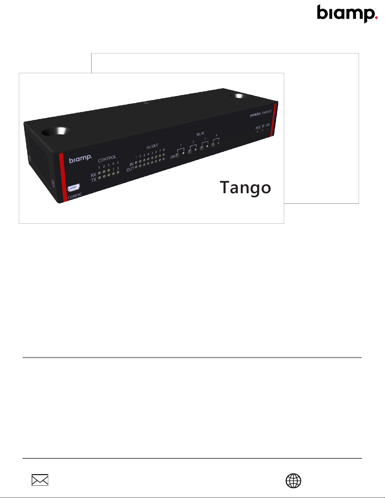
Tango
Touch panel controller
Impera
Installation and Setup Guide
INSTALLATION CONSIDERATIONS
• The Tango controls room AV systems using connected Biamp touch panel displays and
keypads as the user interface devices.
• The controller can be mounted freestanding on desktops, secured to a flat surface such as
a table bottom, or in a 19-inch AV equipment rack using a Biamp rack shelf.
• PoE powered: Use a compliant PoE power supply or switch. PoE injector not included.
• An infrared learner sensor is located on the front panel (IR).
• The controller and AV system devices are configured using Biamp’s Project Designer utility
software.
Page 2
1
2 3 4
5 6 7
CONFIG
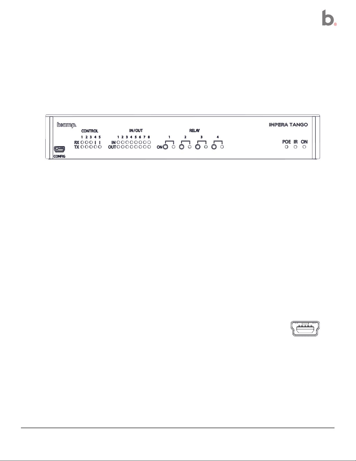
Device Layout
Front Panel Layout and Descriptions
1. Mini USB-B 5P configuration port
2. RS-232 control status indicators
3. General purpose input / output indicators
4. Paired relay test buttons and indicators
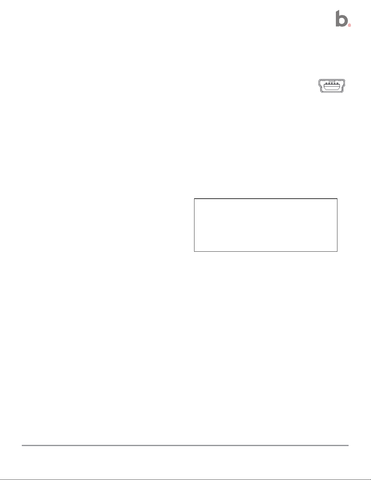
Configuration USB Port
The mini-B USB port is used to upload configuration files to the Tango
controller.
5. PoE output status indicator
6. IR Learner input sensor
7. Power on status and error
indicator
2
Impera Tango Installation and Setup Guide
Page 3

Control Indicators
These RS-232 / IR transmitter LED status indicators illuminate when there
are active communications on the controller’s RS-232 and IR terminals.
General Purpose Input / Output Indicators
These input and output indicators illuminate when a high signal is
present on the corresponding ports.
• Input high signal light yellow
• Output high signal light green
The indicator is dark when a low signal is present on the corresponding port.
Relay Buttons and Indicators
The 4 relay buttons test the functionality of devices connected to
the back panel relay terminals. During operation, the indicators
illuminate when the controller is controlling devices connected to
the corresponding relay terminals.
Caution: Multiple relays can be activated at the same time, potentially damaging connected
equipment.
PoE Output Status Indicator States (POE)
• Continually on – A compatible PoE device is connected to the PoE
output.
• Flashing slow – No PoE enabled device connected.
• Flashing fast – Error or overload on a connected PoE device
3
Impera Tango Installation and Setup Guide
Page 4
1
1
1
2 3 4 5 6
7
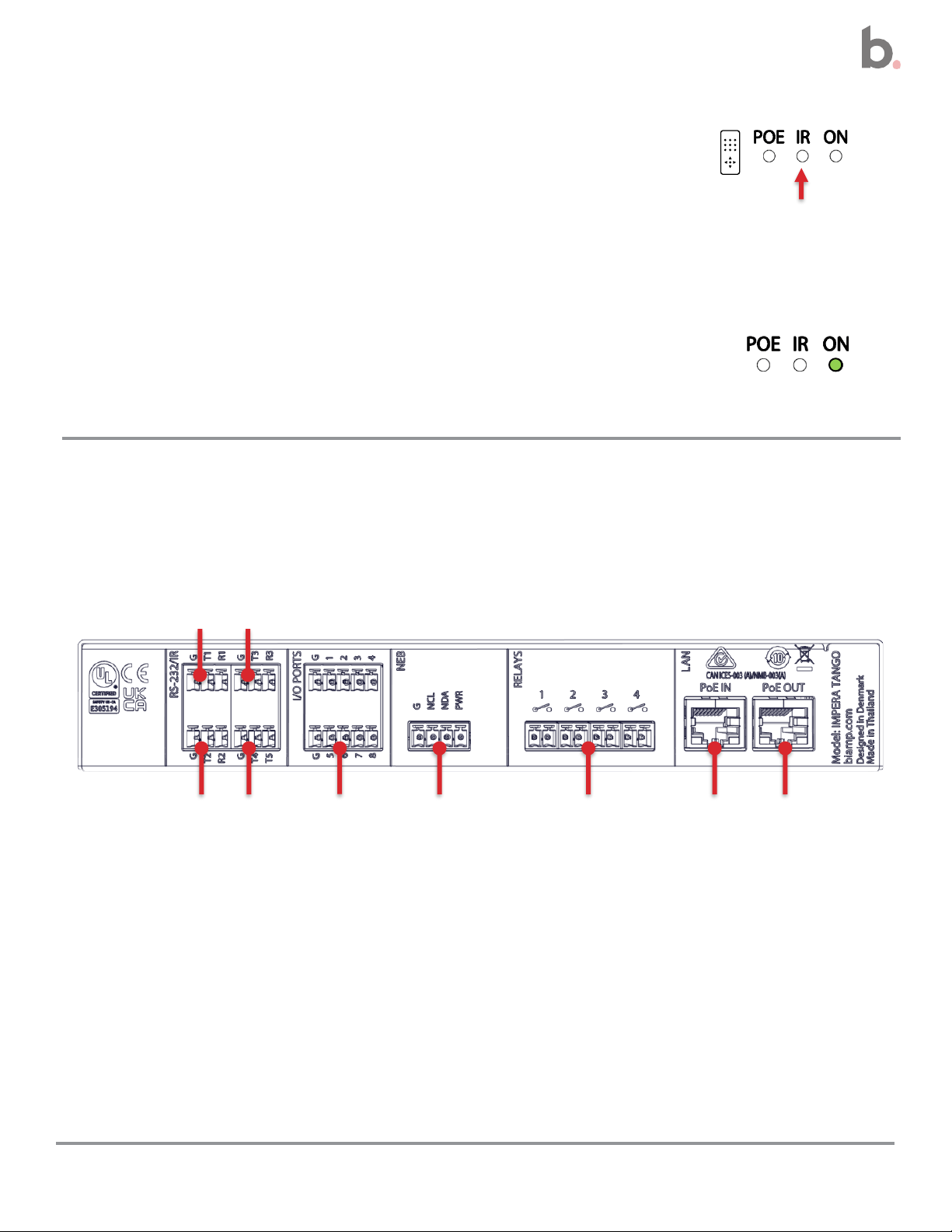
IR Learner Function Sensor Lens (IR)
The IR Learner sensor captures infrared control codes from
remote control devices while using Biamp’s Device Editor utility.
• Captures sequences in the 20 to 60 kHz range.
On light Indications (ON)
• Blue – The controller is starting up
• Green – The controller is powered and running normally
• Flashing red – Error mode
Rear Panel Layout
Details on connection point functionality and wiring configurations can be found in the
Connect the Controller procedure starting on page 8.
Connections
1. 3 bidirectional RS232 or IR terminals
2. 2 unidirectional RS232 or IR transmit terminals
3. 8 digital general input-output ports
4
4. Native Expansion Bus (NEB)
5. 4 potential-free relays
6. RJ-45 LAN connector with PoE input (LAN)
7. RJ-45 Lan connector with PoE output (LAN)
Impera Tango Installation and Setup Guide
Page 5

Installation and Setup Overviews
Perform the procedures listed in this section to install and set up the controller.
Installation
These procedures and options are described in the Installation section of this guide.
✓ Place or secure the controller in its installation location, page 7
• Option 1: Freestanding on a horizontal surface
• Option 2: Secured to a flat surface
• Option 3: In a standard 19-inch AV equipment rack
o Required rack shelf sold separately
✓ Connect the controller
• Connect the AV system devices to the controller, page 8
o Do not connect to a PoE source at this time
• Connect a compliant PoE source to the PoE IN port, page 12
Continued on next page
5
Impera Tango Installation and Setup Guide
Page 6

Setup
These procedures and options are described in the Setup section of this guide.
✓ Download Biamp’s Project Designer software, page 15
• This utility is used to configure connected devices, including the graphic user interfaces
of connected display panels.
✓ Configure the system and devices, page 16
✓ (Optional) download Biamp’s Device Editor utility, page 18
• This software is required to use the Tango’s IR learner function for incorporating remote
control devices with infrared transmitters.
6
Impera Tango Installation and Setup Guide
Page 7

Installation
Install the Controller
Options
Explanation: The Caution sticker on the device denotes that it must not be installed at a
height greater than 2 meters. Installing above this height risks injury due to falling objects.
Freestanding on a Flat Surface
1. Mount the 4 included adhesive feet on the bottom of the controller.
2. Place the unit on a desk or other flat, horizontal top surface.
Secured to a Flat Surface
Use the two self-tapping screws included to secure the controller to flat surface.
1. Position and hold the controller on the surface it is to be mounted on.
o The bottom of the controller must be against the surface, and the screws inserted
through the holes on the top of the controller.
2. Fasten the controller in place, screwing both self-tapping screws through the mounting
holes into the mounting surface.
o Use the included anchors for mounting on a drywall surface.
Standard 19-inch Rack (480 mm)
The controller can be mounted in a 19-inch standard AV equipment rack using the included
MA4x35mm screws and a Biamp rack shelf PN – 910.0116.900 RMS-1.
7
Impera Tango Installation and Setup Guide
Page 8
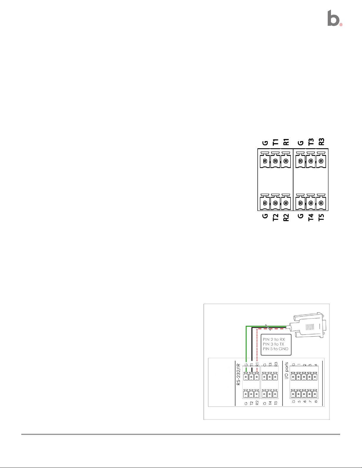
• Pin 5 to G (Ground)
• Pin 3 to T1
• Pin 2 to R1
Connect the Controller
Connect the controller terminals to the room’s AV system devices. Do not connect the PoE IN
port or otherwise power up the controller at this time.
• See page 12 for connecting the PoE source or injector to the PoE IN port after the
current procedure is complete.
RS-232 and IR Connections
Using Biamp Project Designer software the T and R terminals may be
configured as an RS-232 terminal, or the T terminal may be configured
as an IR emitter.
Note: If configured as an IR emitter, the R terminal will not be used.
One-Way Communications: The T4 and T5 terminals are dedicated
unidirectional transmit terminals.
Two-Way Communications: The following terminals can be paired for bidirectional transmit
and receive communications. These can be connected to devices requiring a reply function
such as projectors.
• T1 + R1
• T2 + R2
• T3 + R3
Connection Figuration Examples
Bidirectional RS232 example
8
Impera Tango Installation and Setup Guide
Page 9
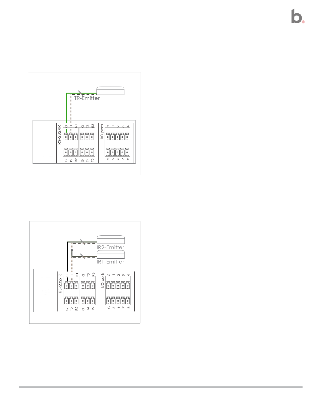
• Connect the IR-1 emitter to T1 with
the white-striped wire
• Connect the black wire on the IR-1
emitter to the IR-2 emitter
• Connect the black wire from the IR-
2 emitter to paired ground (G)
• Emitter to T1
• Ground wire to the paired ground (G)
Connections continued
Unidirectional IR transmitter example
Dual IR transmitter example
9
Impera Tango Installation and Setup Guide
Page 10
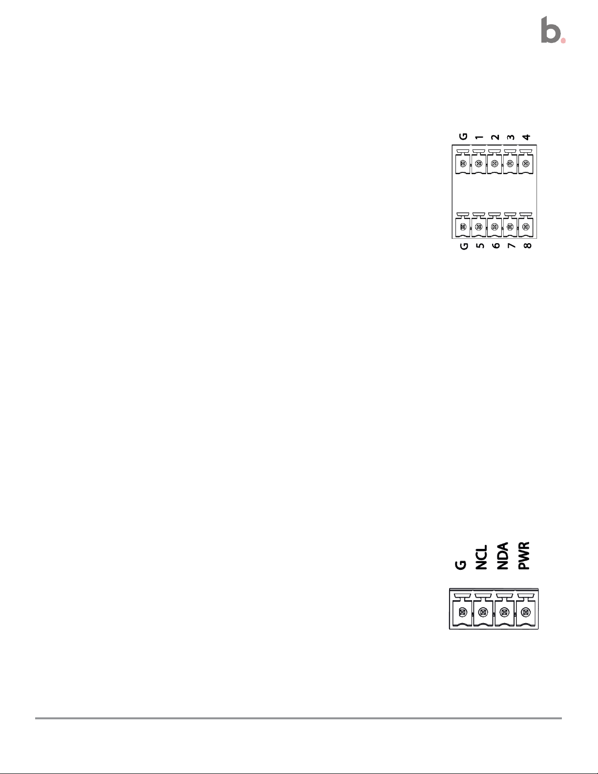
Connections continued
General Input and Output Ports
The controller has 8 general ports, each of which can be configured
as either an output or an input. Each of these I/O ports is available
for connection to devices such as a PIR movement sensor, a
keyboard lock, relays, or for other compatible uses.
Potential: These ports are not potential-free. External relays may be
needed to prevent ground loops depending on the application.
Outputs:
• When used as outputs, the I/O ports are active low.
• When activated, the I/O ports are tied to ground (G) through a FET transistor.
o Also known as an open drain or collector function.
• Each I/O can draw up to 24VDC/500mA.
Inputs:
• When used as inputs, the applied voltage must be below 1 VDC to be accepted as LOW,
and above 4 VDC (but below 24 VDC) to be accepted as HIGH.
• The inputs are default HIGH and must be connected to a ground to change state.
Native Expansion Bus (NEB)
The NEB supports up to 5 expansion bus devices such as keypads,
level controls, and expanders.
The NEB port includes an extender allowing up to 131 feet (40m) of
separation between the controller and devices connected using the
Biamp extender module. The extender module is required for making
connections at these distances.
10
Impera Tango Installation and Setup Guide
Page 11
LED Color
Light Off
Light On
Light Blinking
Yellow No Link
Link
Activity
Green
10 Mbit
100 Mbit
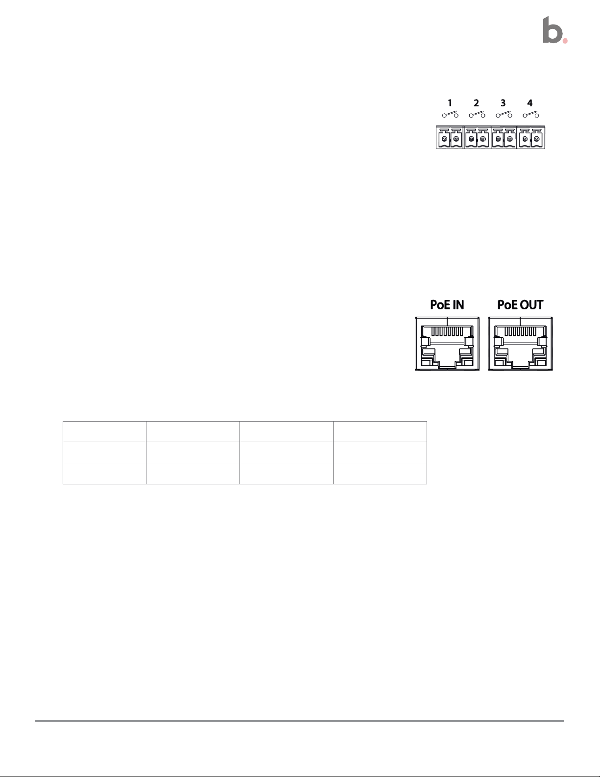
Connections continued
Potential-Free Relays
Default open relays: Each relay is open when off, meaning there is
no connection in the off state.
Caution: Multiple relays can be activated at the same time, potentially damaging connected
equipment.
LAN PoE OUT
The PoE IN will be connected in the next step.
MDI-X: Both the In and Out PoE ports come with auto MDI-X
interfaces. A LAN switch is not required to connect these ports to
other devices.
Port LED indicators: Each comes with a yellow LED indicating
the link status and a green LED indicating the link speed.
PoE Out Port
• This port provides power over Ethernet from the Tango controller to a connected
PoE-enabled device.
• The connected device must conform to IEEE802.3af
11
Impera Tango Installation and Setup Guide
Page 12
Note: When switching from USB power
to PoE power, the device may reboot.
Avoid this issue by keeping the USB
power source ungrounded. (e.g., a laptop
running on battery power)
Do not connect the Mini USB 5P
The mini-USB is only used for uploading configuration files to the controller. It
cannot be used as a connection point to devices controlled by the controller.
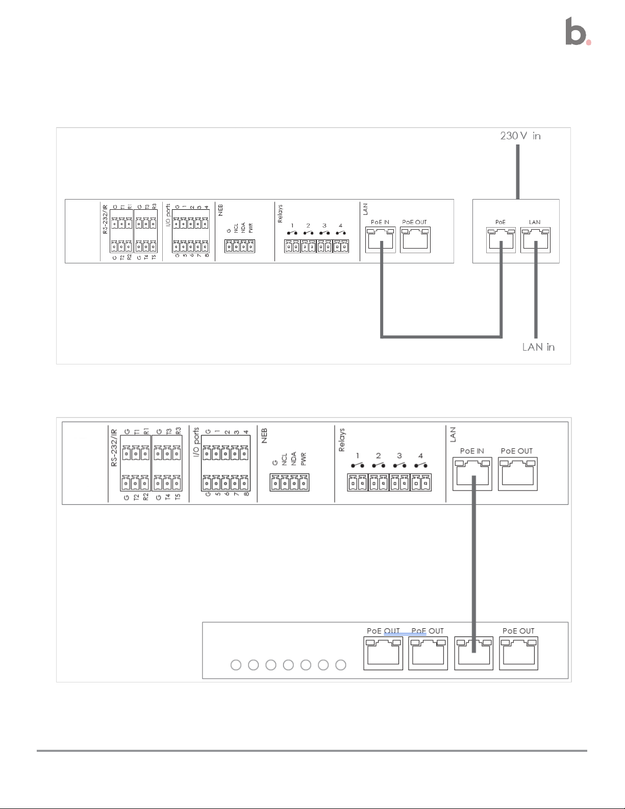
Connect to the Power Over Ethernet Source
The PoE IN connector on the back of the controller provides power over Ethernet to the Tango
controller.
Cable: Use an RJ45 terminated LAN cable.
Connection Options:
• Connect to a PoE Injector.
o The injector must be connected to the PoE IN port in order to enable LAN
functionality.
• Connect to a PoE-enabled switch compliant with IEEE2.3af
Continued on next page
12
Impera Tango Installation and Setup Guide
Page 13
13
Impera Tango Installation and Setup Guide
PoE IN connection continued
PoE injector example
PoE-enabled switch example
Continued on next page
Page 14

14
Impera Tango Installation and Setup Guide
Power Up Cycle Indicators
When power cycling a factory-configured device the POE, ON, and the 16 IN/OUT LED
indicator lights will blink.
Relay Test Functionality
Test the functionality of any devices connected to the relay terminals using the corresponding
test buttons on the controller front panel. When the test button is pressed, the LEDs will
indicate if the relay is activated (green) or not activated (off)
Page 15

Controller Setup
Download Biamp Project Designer Software
The Project Designer utility software provides drag-and-drop functionality for configuring the
graphical user interface (GUI) of a connected touch panel or another compatible interface
device. Additionally, Designer is used for setting the hardware functions of the Tango controller
and those of audio / visual devices attached to the system. See the next page for specifics.
Project Designer also provides the following:
• An extensive driver library for incorporating Biamp and third-party devices in the AV
system.
• Automated generation of project documentation.
IR Learner: Download Biamp’s Device Editor to use the controller’s IR learner function. See
page 18. The device may need to be factory reset prior to using IR learning. See page 19.
Download Site
Project Designer can be downloaded from Biamp.com.
• Click here: Biamp Project Designer
Support Articles
Technical support articles for Project Designer can be found on Biamp’s Cornerstone
knowledgebase support site.
• Click Here: Biamp Control - Biamp Cornerstone
Training
An online course covering Optimized Control Design for Impera systems can be registered for
on Biamp’s training website. This includes how to configure the Impera Tango using Biamp
Project Designer software.
• Click here: Biamp Training - InPerson and Online Training, Certification Courses
o Look under the “Impera Learning Path” section.
15
Impera Tango Installation and Setup Guide
Page 16

Configure the System
Use the Biamp Project Designer software to configure the controller and the AV
system it will control.
1. Configure the controller
• Configure and assign functions to the RS232 / IR and GPIO ports if
required.
• Assign any functions required for the expansion bus.
• Set up the relay port functions if required.
2. Configure the connected system user interface device.
Touch Panel Notes: When connected to an Apprimo touch panel, the Tango serves up
a web page on the touch screen. The controller uses WebSockets as the interface
between the touch panel and itself.
User interface tasks:
• Set up the graphical user interface on the touch panel or control pad.
• Assign functions to any hardware buttons.
• Assign any signal outputs to any LEDs indicators on the interface device.
3. Configure the system and attached audio / visual devices.
Continued on next page
16
Impera Tango Installation and Setup Guide
Page 17
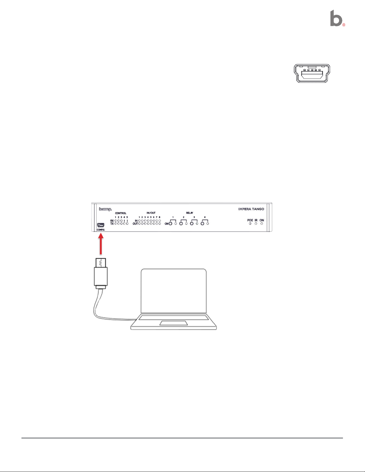
4. Upload the configuration file to the controller.
The configuration file can be uploaded via:
• The controller’s Mini USB 5 port
o The controller can be powered using this port while uploading a
configuration file.
o Uploads can also be safely performed using this port while the controller is
connected to a LAN ethernet cable that is supplying power.
• A LAN connection over the PoE IN port
17
Impera Tango Installation and Setup Guide
Page 18

(Optional) Download Biamp’s Device Editor Utility
Required to use the IR learner function.
Download Site
The software can be downloaded from Biamp.com.
• Click here: Downloads (biamp.com)
Select:
1. Products: Impera
2. Resource Type: Software/Firmware
a. Uncheck the default Datasheets option
Support Articles
Technical support articles for Device Editor can be found on Biamp’s Cornerstone
knowledgebase support site.
• Click Here: Getting started with Biamp Device Editor - Biamp Cornerstone
18
Impera Tango Installation and Setup Guide
Page 19
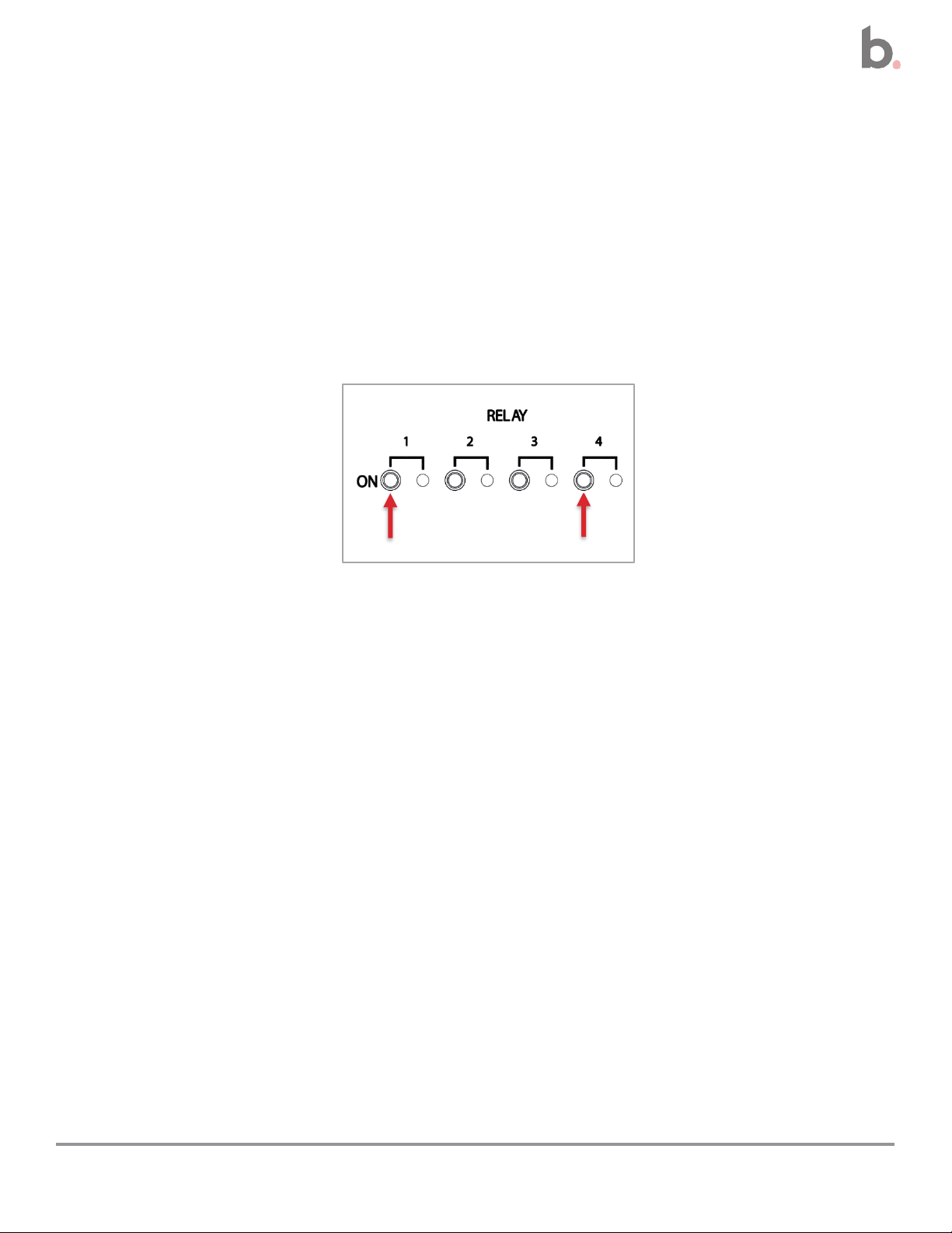
Operations Notes
Restoring to Factory Settings
This deletes the uploaded configuration file and network settings, restoring the controller to its
original factory settings. This does not affect the firmware of the controller.
1. Remove all PoE/USB power.
2. Press and hold relay buttons 1 and 4 and apply power.
o Continue holding the relay buttons until all IN/OUT LED indicators begin flashing.
3. After the reboot completes, LED indicators 1 and 2 will continue flashing. The unit has
been reset to its factory settings.
19
Impera Tango Installation and Setup Guide
Page 20
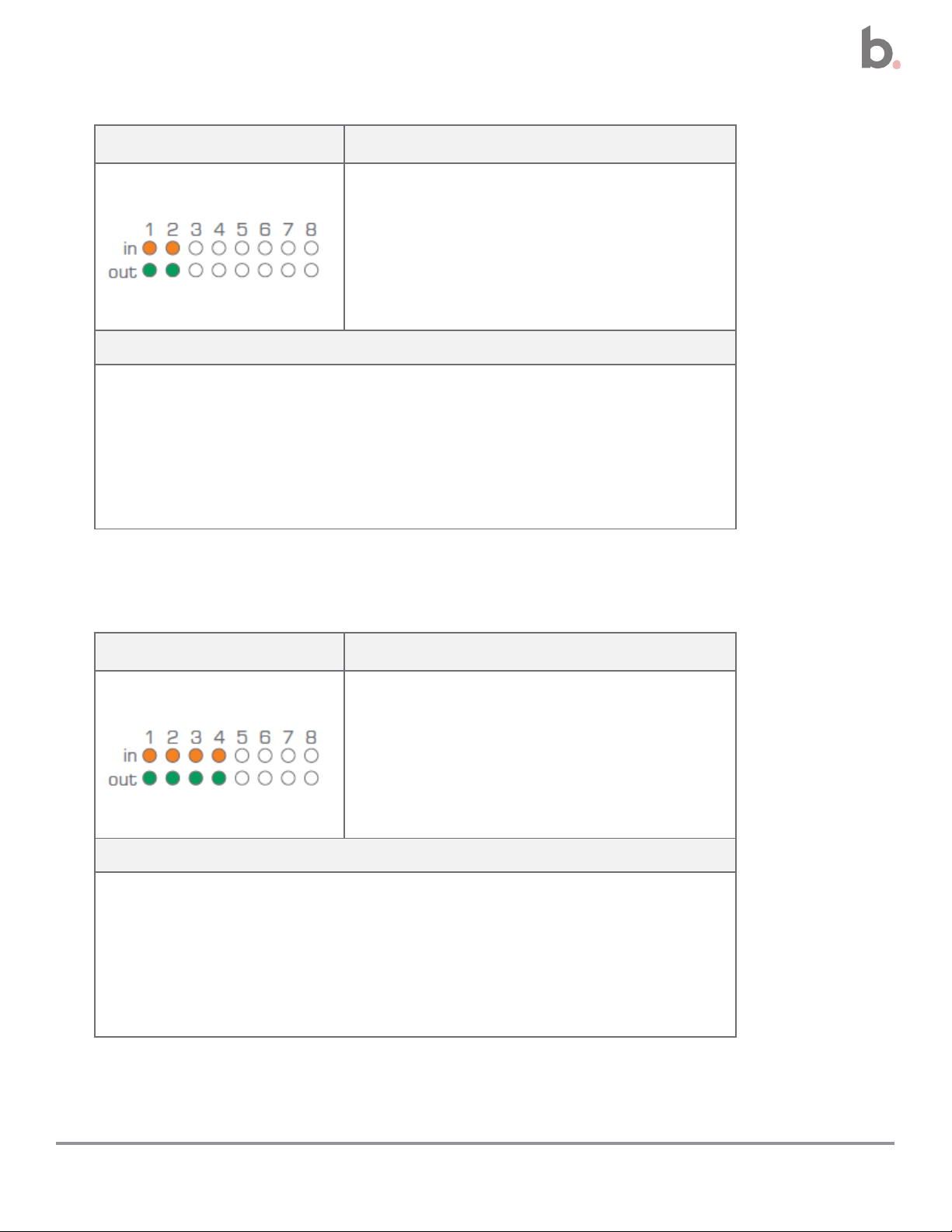
LED Pattern
Error
No connection to one or more of the
native expansion bus ports that have an
assigned use in the Project Designer
configuration file.
Solutions
• Check that the NEB ports used in the configuration file are
configured correctly.
• Power cycle: Disconnect the controller from the power
source and leave depowered for 20 seconds. Then
reconnect and repower.
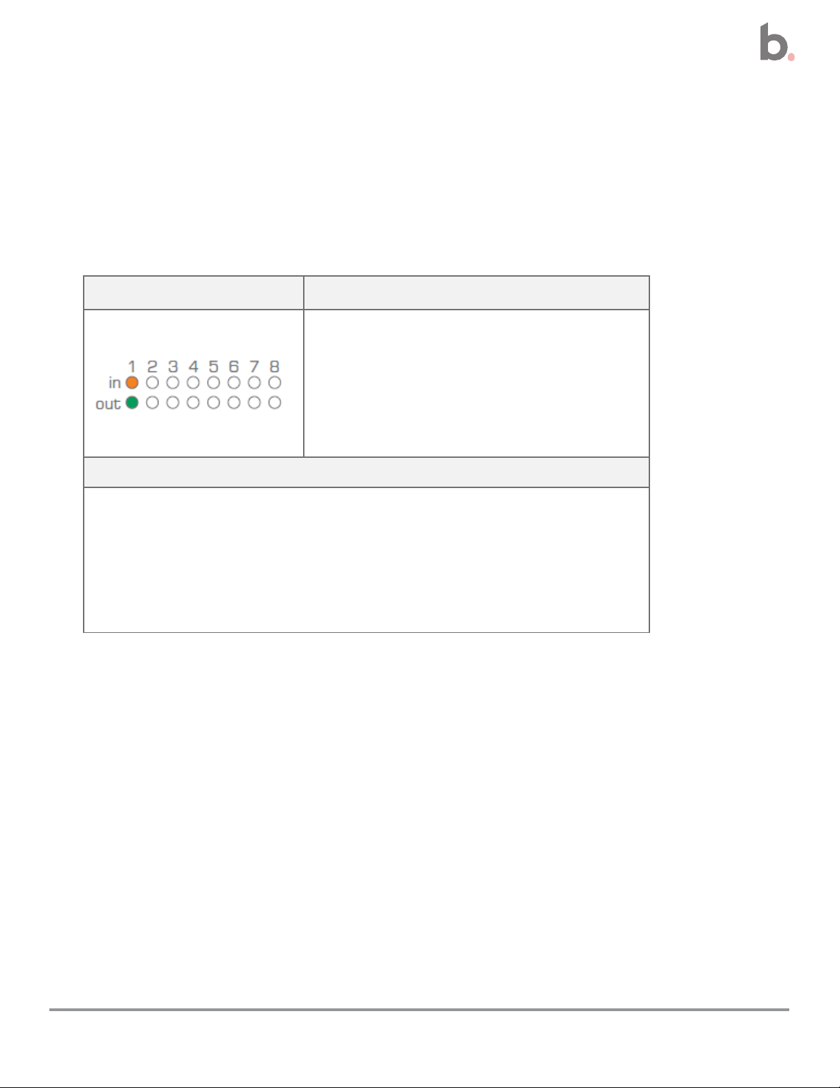
Appendix: LED Error Indicators
The front-panel IN/OUT LED indicators display error codes in the event of an error.
Continued on next page
20
Impera Tango Installation and Setup Guide
Page 21
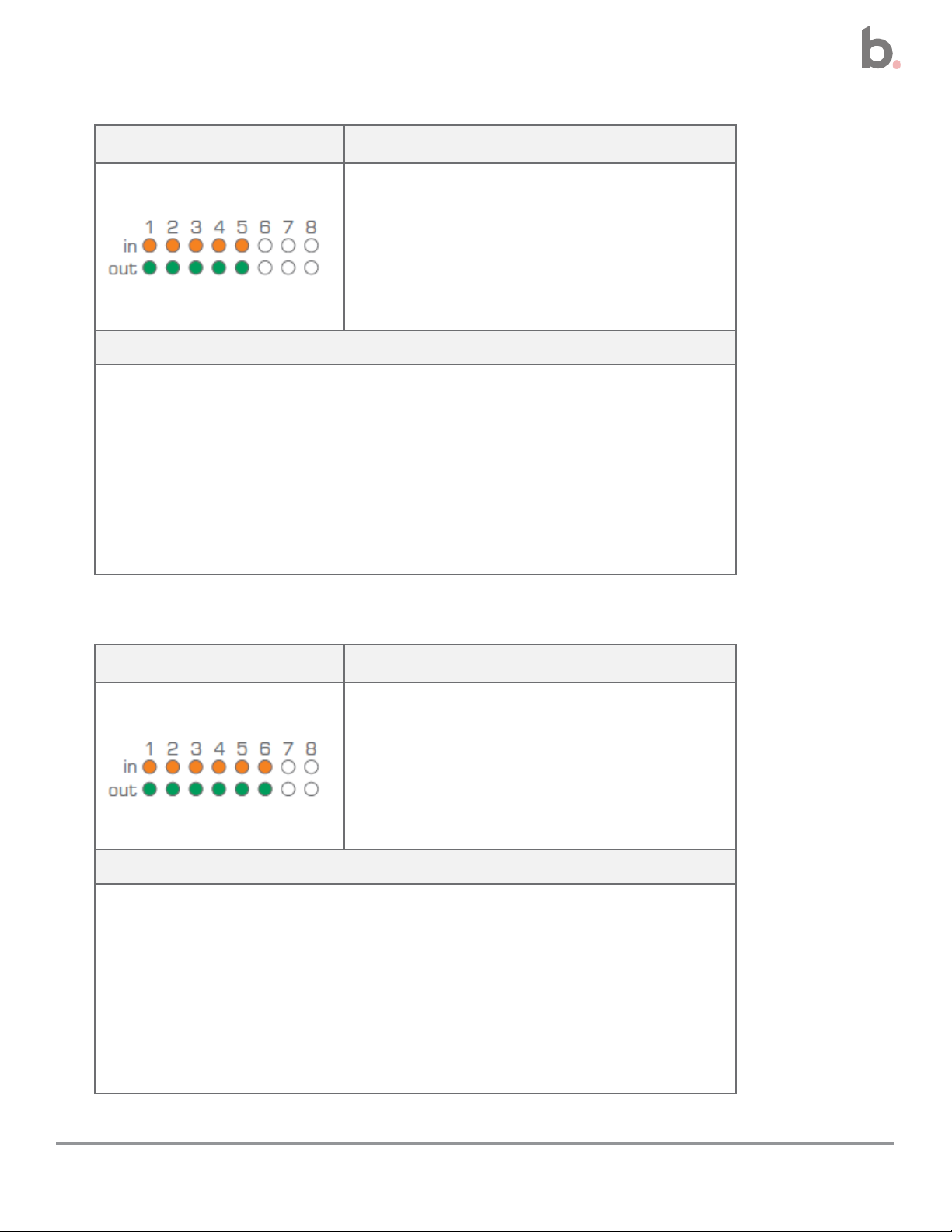
LED Pattern
Error
No Project Designer configuration file
has been found on the controller.
Solutions
• Reload: Attempt to upload the configuration file again.
• Verify: If reloading does not solve the problem. there may
be a problem in the configuration file. Try uploading an
empty project file and check if the error indicator turns off.
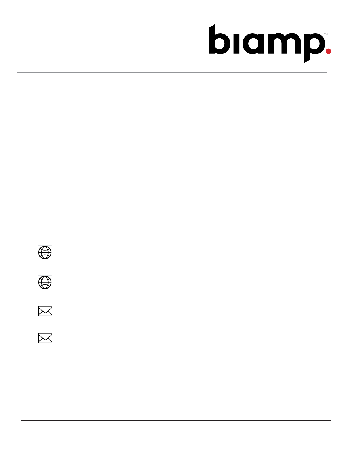
LED Pattern
Error
An unknown error has occurred.
Solutions
• Power cycle: Turn off power to the controller for a minimum of
20 seconds. Then repower the controller.
21
Impera Tango Installation and Setup Guide
Page 22
LED Pattern
Error
No contact with the Biamp extension
unit.
Solutions
• Verify the extension serial number entered in the Project
Designer configuration file matches that of the Biamp
extension device.
• Connection checks: Check the network or RS-232
connection from the control. system to the extension
device. Check the network or RS-232 connection on the
Tango and all connected network devices.
LED Pattern
Error
Incompatible firmware version loaded
in the Biamp extension device.
Solutions
• Verify the extension serial number entered in the Project
Designer configuration file matches that of the Biamp
extension device.
• Connection checks: Check the network or RS-232
connection from the control. system to the extension unit.
Check the network or RS-232 connection on the Tango
and all connected network units.
22
Impera Tango Installation and Setup Guide
Page 23
December 13, 2023
www.biamp.com
www.support.biamp.com
Support@biamp.com
9300 SW Gemini Drive Beaverton, OR 978008 USA
Warranty: biamp.com/legal/warranty-information
Safety & Compliance: biamp.com/compliance
 Loading...