

Page 1

®
Vocia
GPIO-1
Operation Manual
January 2013
Biamp Systems, 9300 SW Gemini Drive, Beaverton, Oregon 97008 U.S.A. (503) 641-7287 www.biamp.com
Page 2

IMPORTANT SAFETY INSTRUCTIONS
IMPORTANT SAFETY INSTRUCTIONS
1) Read these instructions.
2) Keep these instructions.
3) Heed all warnings.
4) Follow all instructions.
5) Do not use this product near water.
6) Clean only with dry cloth.
7) Do not block ventilation openings.
Install in accordance with the
manufacturer’s instructions.
8) Do not install near any heat
sources such as radiators, heat
registers, stoves, or other product
(including amplifiers) that produce
heat.
9) Only use attachments/accessories
specified by the manufacturer.
WARNING - To reduce the risk of fire or electric shock, do not expose this product to rain or
moisture.
10) Use only with equipment rack, cart,
stand or table designed to provide adequate
mechanical strength, heat dissipation and
securement to the building structure.
When a cart is used, use
caution when moving the
cart and product combination
to avoid injury from tip-over.
11) Unplug this product during lightning
storms or when unused for long periods of
time.
12) Refer all servicing to qualified service
personnel. Servicing is required when the
product has been damaged in any way, such
as power-supply cord or plug is damaged,
liquid has been spilled or objects have fallen
into the product, the product has been
exposed to rain or moisture, does not
operate normally, or has been dropped.
CAUTION - The Installation steps for ‘Auxiliary Power’ are for use by qualified personnel
only and must comply with all local codes.
National Electrical Code, ANSI/NFPA 70 for United States.
Canadian Electrical Code, Part 1, CSA C22.1, Sections 2-128, 12-010(3) and 12-100
for Canada.
Explanation of safety related symbols - Product labeling and the operation manual may
use the internationally recognized symbols defined below to note safety messages.
Lightning Bolt: Hazardous Live voltages present when this unit is in operation. Do
not touch terminals marked with this symbol while the unit is connected to live power.
Exclamation Point: Replace components (i.e. fuses) only with the values specified by
the manufacturer. Failure to do so will compromise safe operation of this unit.
2
Page 3

TABLE OF CONTENTS
VOCIA GENERAL PURPOSE INPUT OUTPUT DEVICE (GPIO-1) .........................4
Features ..........................................................................................4
Network ..........................................................................................5
Device ID .........................................................................................5
Input Connectors ...................................................................................6
Output Connectors .................................................................................7
Power ............................................................................................8
SUGGESTED WIRING ........................................................................... 9
SPECIFICATIONS ................................................................................12
BLOCK DIAGRAM ...............................................................................12
WARRANTY ......................................................................................13
FCC COMPLIANCE ..............................................................................14
EC DECLARATION ..............................................................................15
EU ROHS COMPLIANCE .......................................................................16
3
Page 4

VOCIA GENERAL PURPOSE INPUT OUTPUT DEVICE (GPIO-1)
The GPIO-1 provides sixteen general purpose inputs and sixteen general purpose outputs to control various aspects of a Vocia system.
The GPIO-1 is a monitored device and can be used in life safety applications where more logic inputs or outputs are required. The GPIO-1
has dual powering from PoE Ethernet ports and alternate powering from dual 24V DC inputs. In the event of power loss changeover
between power sources will provide uninterrupted operation.
FEATURES
• Sixteen general purpose logic input and outputs
• Device monitoring
• Able to be used to directly interface with re alarm and emergency equipment
• PoE capable with alternate powering from auxiliary 24V DC supply (dual inputs)
• Software-congurable
• Control over a single Ethernet cable
• Dual Ethernet ports for redundancy
• Rotary switches for device identication
• IP30 Compliant
• CE marked, UL listed and RoHS compliant
• Covered by Biamp Systems’ ve year warranty
4
Page 5

GPIO-1 SETUP AND USE
Setup and Use
The Vocia software provides the interface for conguring and programming the GPIO-1. The information supplied by this manual relates
to hardware installation, physical connections and device information. For more details on the software setup please consult the Vocia
Software Help File.
Network
The GPIO-1 is designed to be used in a single Vocia World and utilizes the Vocia CobraNet LAN to communicate.
The unit has two monitored RJ45 Ethernet Network connectors to facilitate redundant connections. The Primary connection will always have
priority over the Secondary connection. Monitoring of the secondary connection can be disabled in the software.
A green power LED is provided and illuminates when PoE power is applied to the unit via either Network port.
Each RJ45 connector uses two LEDs to indicate Ethernet link and network activity (see table below).
Left LED Right LED Description
None None No data connectivity
Yellow Flashing green Network link established. Port is in use
None Flashing green Network Link established. Typically seen on the Secondary port when acting as a failover to the
Primary connection
The maximum distance between any unit and an Ethernet switch is 100 meters (328 feet) when using copper cabling. Additional
Ethernet switches and/or ber-optic cable can be used to further extend distances between devices on a network.
Device ID
The rotary ID switches are located on the GPIO-1 and give the unit a unique Device ID. The switches
are in hexadecimal format. All GPIO-1 units must have a unique Device ID to function within a Vocia
Paging World (i.e., it is not possible to have two GPIO-1 units with the same Device ID of hex 07). To
assign a Device ID of hex 07, turn the MSB switch to 0 and turn the LSB switch to 7. To create an ID
of hex B7, turn the MSB switch to B and turn the LSB switch to 7. Device ID switches should be set
using a 0.1 inch (2.5mm) to 0.12 inch (3.0mm) at blade screwdriver. More information on setting IDs and the hexadecimal numbering
scheme used in Vocia can be found in the Vocia Help File.
Please note: Changes made to the Device ID while connected to the network require a power cycle of the device in order to take effect.
5
Page 6

GPIO-1 SETUP AND USE
Input Connectors
Sixteen parallel input connections are provided on the GPIO-1 as well as Isolated Ground and Ground connections. Under software control
the logic level of each input can be set independently to operate one of three ways.
• TTL: 2V to 5V logic sense. To enable a TTL input, apply a TTL logic high or low with respect to Isolated Ground. This can be
congured in software to detect a low to high or high to low transition.
• High Range: To enable a High Range input, use a dry contact to switch the input to a voltage of 24V DC with respect to Isolated
Ground. This can be congured in software to detect a low to high or high to low transition.
• High Range – Monitored: This circuit is implemented in the same way as the High Range input. This option allows monitoring of each
input for short to ground and open circuit. In order to sense open circuit, a terminating resistor must be tted between each Input and
Isolated Ground at the far end of the circuit being sensed. The Inputs will sense open circuits on the line between its input and the
terminating resistor. Shorts to Isolated Ground are sensed across the entire line being monitored. A 6k8Ω resistor should be used for
each input. If a monitoring fault is detected on any input the logic state or transitions on that input will be ignored until the fault is cleared.
High Range – Monitored inputs require a low to high transition to enable the input (transition direction not congurable).
Pin Label Function
1 Ground
2 1 Input 1
3 2 Input 2
4 Isolated Ground
5 3 Input 3
6 4 Input 4
7 Isolated Ground
8 5 Input 5
9 6 Input 6
10 Isolated Ground
11 7 Input 7
12 8 Input 8
13 Ground
14 9 Input 9
15 10 Input 10
16 Isolated Ground
17 11 Input 11
18 12 Input 12
19 Isolated Ground
20 13 Input 13
21 14 Input 14
22 Isolated Ground
23 15 Input 15
24 16 Input 16
6
Page 7

GPIO-1 SETUP AND USE
Output Connectors
Sixteen parallel outputs are provided on the GPIO-1 as well as Isolated and Chassis Ground connections. Each output is able to accept
either an external positive voltage between 4 and 30V or use the 24V DC 100mA reference voltage provided on the unit. The 24V DC
supply for use with the Aux Power port is not provided with the unit and will need to be sourced locally. Outputs will be monitored for short
to ground, short to supply and if High Range - Monitored is being used, open circuit conditions will be monitored as well. Consideration
should be given to the state of the output when network connectivity is lost. A Voltage Monitor (VM) input is provided in order that a short
to supply reference voltage is incorporated in output Fault monitoring. A voltage of between 4 - 30V is required by the VM input in order for
the outputs to operate.
If the GPIO-1 Outputs are using a High Range Monitored type of circuit the VM input must match or be greater than the highest Output
Voltage being used. If a higher Voltage is seen on the Outputs compared to the VM Input a Short to Supply fault will be indicated.
Pin Label Function
1 Ground
2 Isolated Ground
3 1 Output 1
4 2 Output 2
5 3 Output 3
6 4 Output 4
7 5 Output 5
8 6 Output 6
9 7 Output 7
10 8 Output 8
11 9 Output 9
12 Isolated Ground
13 Ground
14 Isolated Ground
15 10 Output 10
16 11 Output 11
17 12 Output 12
18 13 Output 13
19 14 Output 14
20 15 Output 15
21 16 Output 16
22 VM Voltage Monitor*
23 24V DC 24V DC (100mA limited)
24 Isolated Ground
* The VM Input must always be connected to the 24V supply on Pin 23 or if an external
supply is used the supply voltage should be connected to the VM input.
7
Page 8

GPIO-1 SETUP AND USE
Power
Caution - Due to potential energy hazard, connections to the Auxiliary Power 24V DC
inputs must be made by a qualied electrician or other qualied person as
required to conform with all local codes.
The GPIO-1 will be capable of operation from two power supply types - PoE and 24V DC. Any or all power sources may be connected
concurrently. Loss or return of any power source will not result in interruption to operation. PoE power has priority over 24V DC when both
sources are connected. Fault monitoring of each Power Supply input is enabled by default. The Vocia software allows monitoring to be
enabled or disabled on each power supply.
If PoE Power is to be used an 802.3af Class 3 or 802.3at Type 1, Class 3, compliant PoE switch or mid-span adapter is required to either
or both Ethernet ports.
When power is present at either or both of the 24V Aux power inputs the adjacent green power LED indicator will illuminate. When PoE
power is present at either or both of the Ethernet ports the adjacent green power LED indicator will illuminate.
Pin Label Function
1 24V Aux Power 1 24V (+)
2 0V Aux Power 1 24V (–)
3 24V Aux Power 2 24V (+)
4 0V Aux Power 2 24V (–)
8
Page 9

SUGGESTED WIRING
Input - High Range Monitored – Active High - 24VDC Locally Sourced
Notes: Vocia software congured as High Range Monitored - Active State High.
Circuit shown in Low State
Input - High Range Monitored – Active High - 24VDC Externally Sourced
Notes: Vocia software congured as High Range Monitored - Active State High.
Circuit shown in Low State
Input - High Range Unmonitored – Active High - 24VDC Locally Sourced
Notes: Vocia software congured as High Range - Active State High.
Circuit shown in Low State
Input - High Range Unmonitored – Active High - 24VDC Externally Sourced
Notes: Vocia software congured as High Range - Active State High.
Circuit shown in Low State
9
Page 10

SUGGESTED WIRING
Input - 5V TTL Logic Control
Notes: Low Voltage = 0 – 0.8 VDC. Logic High = 2 – 5VDC.
If congured as Active State High Alarm/Fault/Reset triggers when voltage transitions from Low to High.
If congured as Active State Low Alarm/Fault/Rest triggers when voltage transitions from High to Low.
Outputs Driving a LED Powered from GPIO-1 24V DC Out
Outputs Driving a LED Powered Externally
Outputs Driving a Relay Powered From GPIO-1 24V DC Out
10
Page 11

Outputs Driving a Relay Powered Externally
SUGGESTED WIRING
11
Page 12
GPIO-1 SPECIFICATIONS
Vocia General Purpose Input Output 1 SPECIFICATIONS
General Purpose Outputs
Quantity 16
Type FET Switch, open drain (low side driver)
Max Continuous Current 0.35VA
Current Limit 0.8A
Maximum External Supply 30V DC
VMon Input Shutdown 35V DC
General Purpose Inputs
Quantity 16
High Range Logic Low 0-8V DC
High Range Logic High 12-30V DC
TTL Logic Low 0 – 0.8V
TTL Logic High 2-5V
Voltage Monitor 4-30V DC
Input Transient Protection ± 8kV Peak
Input Isolation 500V RMS
Network Connection: Dual RJ45 with shielded Ethernet cable
(CAT5, CAT5e, CAT6, or CAT7)
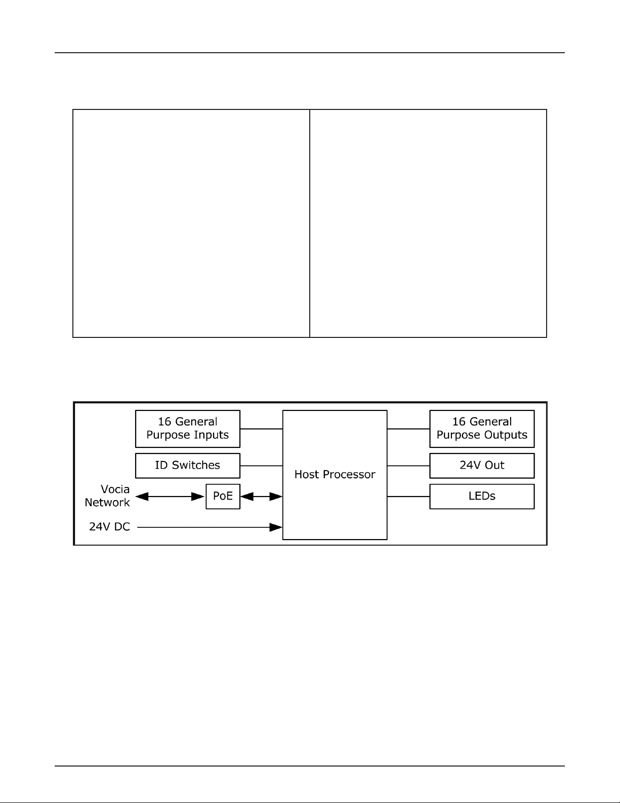
Vocia General Purpose Input Output 1 BLOCK DIAGRAM
Overall Dimensions:
Height: 1.6 Inches (41mm)
Width: 12.5 Inches (370mm)
Depth: 5 Inches (128mm)
Weight: 2.4lbs (1.1kg)
Power
PoE: IEEE 802.3af Class 3
IEEE 802.3at Type 1 Class 3
DC Power : 24V; <100mV Ripple 15W
Environment
Ambient Operating Temperature Range: 23-104° F
(-5 – 40° C)
Humidity: 0 – 95% RH non-condensing
Altitude: 0 – 10,000 Feet (0 - 3,000 Meters) MSL
Compliance: FCC Part 15, Class B
CE Marked
RoHS Directive
UL60065 Listed E215636
C-UL Listed, E215635
C-Tick, N24138 (Australia)
EN54-16 Certified
12
Page 13

GPIO-1 WARRANTY
BIAMP SYSTEMS IS PLEASED TO EXTEND THE FOLLOWING 5-YEAR LIMITED WARRANTY TO THE ORIGINAL PURCHASER OF
THE PROFESSIONAL SOUND EQUIPMENT DESCRIBED IN THIS MANUAL
1. BIAMP Systems warrants to the original purchaser of new products that the product will be free from defects in material and
workmanship for a period of 5 YEARS from the date of purchase from an authorized BIAMP Systems dealer, subject to the
terms and conditions set forth below.
2 If you notify BIAMP during the warranty period that a BIAMP Systems product fails to comply with the warranty, BIAMP Systems
will repair or replace, at BIAMP Systems’ option, the nonconforming product. As a condition to receiving the benets of this warranty,
you must provide BIAMP Systems with documentation that establishes that you were the original purchaser of the products. Such
evidence may consist of your sales receipt from an authorized BIAMP Systems dealer. Transportation and insurance charges to
and from the BIAMP Systems factory for warranty service shall be your responsibility.
3. This warranty will be VOID if the serial number has been removed or defaced; or if the product has been altered, subjected to
damage, abuse or rental usage, repaired by any person not authorized by BIAMP Systems to make repairs; or installed in any
manner that does not comply with BIAMP Systems’ recommendations.
4. Electro-mechanical fans, electrolytic capacitors, gooseneck microphones, cords connecting handheld microphones, hard-drives,
displays, and normal wear and tear of items such as paint, knobs, handles, keypads and covers are not covered under this warranty. All server-based devices are warranted for 3 years only.
5. This warranty is in lieu of all other warranties, expressed or implied. Biamp Systems disclaims all other warranties, expressed or
implied, including, but not limited to, implied warranties of merchantability and tness for a particular purpose.
6. The remedies set forth herein shall be the purchaser’s sole and exclusive remedies with respect to any defective product.
7. No agent, employee, distributor or dealer of Biamp Systems is authorized to modify this warranty or to make additional warranties
on behalf of Biamp Systems. Statements, representations or warranties made by any dealer do not constitute warranties by Biamp
Systems. Biamp Systems shall not be responsible or liable for any statement, representation or warranty made by any dealer or
other person.
8. No action for breach of this warranty may be commenced more than one year after the expiration of this warranty.
9. Biamp systems shall not be liable for special, indirect, incidental, or consequential damages, including lost prots or loss of use
arising out of the purchase, sale, or use of the products, even if BIAMP Systems was advised of the possibility of such damages.
13
013013_585.0318.90B
Page 14

FCC COMPLIANCE
FCC NOTICE - CLASS B DIGITAL DEVICE
NOTE: This equipment has been tested and found to comply with the limits for a Class B digital device, pursuant
to Part 15 of the FCC Rules. These limits are designed to provide reasonable protection against harmful
interference in a residential as well as in a commercial environment. This equipment generates, uses, and can
radiate radio frequency energy and, if not installed and used in accordance with the instructions, may cause
harmful interference to radio communications. However, there is no guarantee that interference will not occur in a
particular installation. If this equipment does cause harmful interference to radio or television reception, which can
be determined by turning the equipment off and on, the user is encouraged to try to correct the interference by
one or more of the following measures: 1) Reorient or relocate the receiving antenna, 2) Increase the separation
between the equipment and receiver, 3) Connect the equipment into an outlet on a circuit different from that to
which the receiver is connected, or 4) Consult the dealer or an experienced radio/TV technician for help.
14
Page 15

COMPLIANCE
DoC VGPIO201205b
EC Declaration of Conformity
Biamp Systems Corporation, as manufacturer having sole responsibility, hereby declares
that our delivered version the following described product complies with the applicable
provisions of the DIRECTIVES below except as noted herein. Any alterations to the product
not agreed upon and directed by Biamp Systems Corporation will invalidate this declaration.
Brand Name: Vocia
Product Description: General Purpose I/O Expander for use with Audio DSP
Model: GPIO-1
®
Applicable EC Directives: Applicable Harmonized Standards:
LVD Directive (2006/95/EC) Safety EN 60065:2002
IEC 60065:2001
EMC Directive (2004/108/EC) Emissions EN 55103-1:2009, Environment E2
Immunity EN 55103-2:1996, Environment E2
RoHS Directive (2011/65/EU) RoHS Recast
Special Considerations for Product Environment or Compliance:
• Use only with CE Marked PoE Insertion Device properly rated and certified to local
regulations, PoE (IEEE 802.3af, Type 1) or PoE Plus (IEEE 802.3at, Type 2).
Use only CE and “LPS” marked 24 VDC External Power Adaptor or DC Source complying
with all local regulations.
Shielded cabling must be used for system connections.
Technical Construction File, Location and Contact:
Biamp Systems Corporation phone: (503) 641.7287
9300 S.W. Gemini Drive fax: (503) 626.0281
Beaverton, OR USA 97008 e-mail: compliance@biamp.com
Signed for and on behalf of Biamp Systems Corporation:
Authorized Representative: Larry Copley, Compliance Engineer
+ Amd 1:2005
Authorized Signature:
Date and Place Issued: May 2012, Beaverton, Oregon USA
15
Page 16

COMPLIANCE
EU RoHS COMPLIANT
This Biamp product, including all attendant cables and accessories
supplied by Biamp, meets all requirements of EU Directives 2011/65/EU
of 8 June 2011, the EU RoHS Recast.
The following information is presented to comply with Chinese law SJ/T11363-2006.
部件名称 (Part Name)
设备机箱(Equipment Chassis)
插拔式接线端子 (Plug-in Terminal Blocks)
扎带 (Cable Ties)
光盘(CD ROM)
手册和其他书面文档 (Manual and Paper Documents)
包装箱和所有包装材料 (Box and Packing Materials)
0:表示该部件所有均质材料中的这种有毒有害物质低于 SJ/T11363-2006 的限制要求.
X:表示该部件中至少有一种均质材料所含的这种有毒有害物质高于 SJ/T11363-2006 的限制要求.
在电触头和(或)镀镉所含的均质材料中,镉及其化合物的含量可以超过 0.01%,但欧盟指令 91/338/EEC(根据欧盟指令
76/769/EEC)限制销售和使用某些危险物质和制剂部分中所禁止的用途除外
An EU RoHS Materials Content Declaration document may be obtained
at www.biamp.com
有
害物 质 表 (Hazardous Substances Table)
Biamp Systems Corporation
通用输入和输出扩展 (General-Purpose Input and Output Expander)
Vocia GPIO-1
有毒有害物质或元素 (Substances)
汞
Cd
Pb 铅 Hg
X O X O O O
O O O O O O
O O O O O O
O O O O O O
O O O O O O
O O O O O O
镉
Cr+6
六价铬
PBB PBDE
在以下一种或多种物质所含的均质材料中,铅及其化合物的含量可以超过 0.1%:
1) 电子元器件中玻璃内所含的铅
2) 铅在钢材中是作为一种合金元素,含量可达 0.35%
3) 铅在铝材中是作为一种合金元素,含量可达 0.4%
4) 铅在铜材中是作为一种合金元素,含量可达 4%
5) 高熔点类焊料中的铅(即铅料合金,铅含量超过 85%)
6) 电子陶瓷部件内的铅
7) 由两种以上元素组成的焊料中所含的铅,用于连接针脚和微处理器包装,其中
铅的含量超过 80% 但低于 85%
8) 顺应针连接系统内的铅
9) 倒装芯片封装中半导体芯片及载体之间形成可靠连接所用焊料中的
在正常使用情况下,中国环保使用期限为 10 年,条件是:
• 环境温度为 0-40C (32-104°F)
• 湿度为 0-95%,无凝结
• 海拔高度为 0-10,000 英尺
• 气流不受阻碍
• 没有水或其他液体进入任何部件
• 电源为 IEEE 802.3af PoE
• 部件没有损坏(损坏部件应立即修理)
• ��������������������
16
 Loading...