

Page 1

Desono™
EX-S Loudspeaker Accessories
Installation & Operation Guide
CMX
EXUB
RIGGING AND ELECTRICAL SAFETY
IMPORTANT: The loudspeakers described in this manual are
designed and intended to be mounted to diering building
surfaces using a variety of rigging hardware, means and
methods. Installation of loudspeakers should only be performed
by trained and qualied personnel. All electrical connections
must conform to applicable city, county, state, and national
(NEC) electrical codes.
IMPORTANT: Refer to the sections on installation and
connections in the EX-S Installation and Operation Guide for
additional information on rigging and electrical safety.
IMPORTANT: When installing loudspeakers outdoors, use a
support system with enough wind-load strength to comply with
applicable codes and standards.
Models
CMX- SM, CMX-LG
EXUB-S6, EXUB-S8
EXUB-S10
IMPORTANT: Please review the safety guide
accompanying this product and the installation instructions
prior to to installing this loudspeaker.
CAUTION: Installation of Biamp loudspeakers should only
be performed by trained and qualied personnel. It is
strongly recommended that a licensed and cer tied
professional structural engineer approve the mounting.
Severe injury and/or loss of life may occur if this product is
improperly installed.
DANGER: It is advised that a safety cable be secured to a
suitable load-bearing point separate from the primary
loudspeaker mounting point, with as little slack as possible
so as not to develop undue kinetic force if the primary
mount were to fail.
ENVIRONMENTAL:
1) This device is not intended for water immersion in
applications requiring UL1480A Certication.
2) This device is not intended for direct exposure to
sunlight in applications requiring UL1480A Certication.
A: 9300 S.W. Gemini Drive Beaverton, OR 97008 USA W: www.biamp.com
Page 2
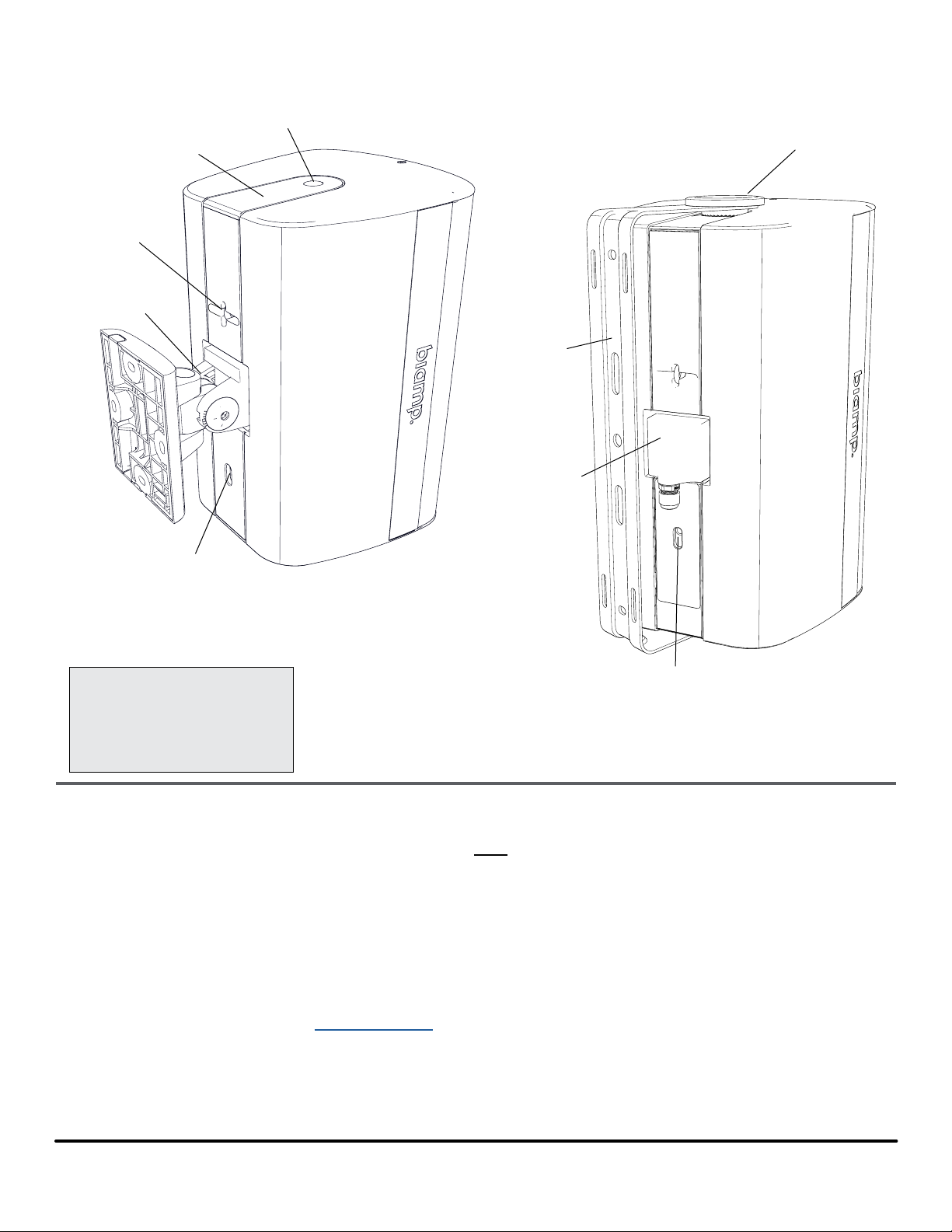
PRODUCT REPRESENTATION
End Cover
Screw Cap
(CMX models only)
Safety Cable
Attachment
ClickMount
Pan-tilt Bracket
Latch release
End Cover
Knob
U-Bracket
ClickPlug
CMX-SM on EX-S6 shown
Tools Needed
• Hex wrenches: 5mm,
5.5mm (or 7/32"), 6mm
• Small flat screwdriver
INSTALLATION
The loudspeaker can be mounted to a variety of surfaces, but must be mounted to
structural load bearing surfaces or substrates (not electrical gang boxes). There
are two mounting options provided for the Desono EX family of loudspeakers: a
ClickMount pan-tilt bracket and an indexing U-Bracket with included waterproof
ClickPlug wiring insert. Wiring can be run to the mounting locations for each of the
mounting options. When installing EX models outdoors, do not aim them upwards.
Doing so will void the warranty and reduce the life of the loudspeaker.
Since the loudspeakers are sold with a mounting option, this installation guide will
describe the method of changing one mounting method to the other. Please review
the EX Surface Mount Loudspeaker Installation guide for complete information
about installation, wiring, and aiming.
Latch release
EXUB-S8 on EX-S8 shown
page 2 Installation and Operation Guide Desono EX-S
Page 3

Attach End Caps for Conversion to ClickMount Pan-tilt Bracket
Remove the U-Bracket, ClickPlug and end knobs from the loudspeaker if they
were previously installed or attached.
End Cap Cover Attachment
1. Slide cover on and seat over the threaded insert (Figure 1).
2. Screw on the cover retention nut with a 6mm hex wrench.
3. Cover the nut with the small cap - insert the rear tabs rst, then push down
the front to fully seat.
Mounting Considerations:
The loudspeaker must be tilted
away from the ClickMount plate when
attaching it to the bracket. Adequate
space must be allowed around the
ClickMount bracket to accommodate
this, so locating the bracket in or close
to a corner is not advised. Refer to the
documentation accompanying the
accessory for spacing for both vertical
and horizontal orientations.
321
Figure 1. End cover attachment
Install the ClickMount Pan-tilt Bracket
Refer to the EX-S installation guide (manual) by scanning the QR code at right or
clicking on the link. Install the ClickMount bracket per the instructions.
1. Adjust the tap switch to the desired setting.
2. Mount the loudspeaker to the bracket (Figure 2).
3. Secure the loudspeaker with a safety cable attached to the loop on the
rear.
4. Aim the loudspeaker, then fully tighten the bracket with the hex wrench. Do
not overtighten.
bia.mp/EX-S_pubs
CLICK
WARNING: Fully support the
loudspeaker until it is clicked in
CLICK
Figure 2. Mount loudspeaker on bracket
loudspeaker will pull / angle the
ClickMount arm down if it isn't tight.
place. The weight of the
Desono EX-S Installation and Operation Guide page 3
Page 4

Installation - ClickMount Pan-tilt Bracket (continued)
To remove loudspeaker from the bracket
The loudspeaker can be removed from the ClickMount pan-tilt bracket as follows:
1. Insert a 5mm hex wrench into the hole within the slot in the middle of the
label on the rear panel (Figure 3a).
2. Pull down (or toward the base) and the latch will release and remain in
the "unlocked" position until the speaker is removed from the bracket. The
loudspeaker must be fully supported as you release the latch. See Warning
at right.
3. Rotate the bottom of the speaker away from the ClickMount Bracket. See
Figure 3b.
WARNING: When you release
the clickmount latch - the
loudspeaker will fall o the
ClickMount bracket! Fully support the
cabinet while releasing the latch. This is
especially important with horizontallymounted EX loudspeakers! The safety
cable should be in place to take the
strain but the loudspeaker will be
dangling.
Figure 3. Insert hex wrench into hole and pull down to release latch
Figure 3b. Lift and rotate bottom of speaker away from the ClickMount bracket
page 4 Installation and Operation Guide Desono EX-S
Page 5

End Cap Cover Removal for U-Bracket Installation
The end cap covers can be removed if you purchased a unit with a ClickMount
pan-tilt bracket and need to change it to a U-Bracket mount with the appropriate
accessory EXUB-S kit.
They are sized for each loudspeaker model (S6, S8, S10/S10SUB).
Cover Removal
1. Insert a small screwdriver under the front end of the circular cap. Pry up
and remove the cap.
1
Tools Needed
• Small flat screwdriver
• 6 mm hex wrench
2. Use a 6mm hex wrench to
remove the cover retention nut.
3. Use a small screwdriver to lift the
front end of the cover.
4. Slide cover o, and repeat for the
other cover
3
2
4
Figure 4. Remove end cap covers
Desono EX-S Installation and Operation Guide page 5
Page 6

Installation - U-Bracket
The U-Bracket can be connected to a center suspension post or against the wall,
ceiling or other flat surface. It can also be mounted to a variety of third party stand
and pole adapters. Refer to the EX-S Installation guide for full instructions.
1. Mount U-Bracket to wall prior to loudspeaker installation. If mounting in
a horizontal orientation on a wall, the slots should face up - see image at
right.
2. Sucient cable should be pulled through the bracket holes to create a drip
loop (damp/wet applications) with enough extra to connect to the ClickPlug.
Cable
channel
Structure Mounting Points
(Hardware not provided)
Mounting Considerations:
Leave appropriate spacing on
either side of the U-Bracket to
be able to access the knobs with
hands and tools. Refer to the manual
for assembly and spacing for both
horizontal and vertical orientations.
3. Wire ClickPlug as shown (Figure 5) and in the EX-S Install Guide leaving
enough for the likely mounting angle and a drip loop for damp/wet
applications.
4. Adjust the tap switch to the desired setting.
Cable / Wire Size
ClickPlug Cable gland nut will accept
a 4-8mm (0.15-.3 in) diameter cable
or 2 pairs 1.5mm² (16 ga) or 1 pair
2.5mm² (14 ga). For outside or
moisture-rich environments - round
SJOW cable or equivalent is advised
to provide a weather-resistant seal in
the tightened gland nut. Forming the
cable into a drip loop will also prevent
any moisture migrating into the gland
nut.
Tools Needed
• 5.5mm (or 7/32") Hex wrench
Figure 5. Wire the ClickPlug
page 6 Installation and Operation Guide Desono EX-S
Page 7

Installation - U-Bracket (continued)
Attach the Loudspeaker to the U-Bracket
Refer to the EX-S Install guide (manual) by clicking on this link: bia.mp/EX-S_pubs.
5. Mount the loudspeaker to the U-bracket per the instructions since the
loudspeaker must be mounted in a specic way to correctly engage and use
the indexing aiming feature. The loudspeaker will rotate 200° on the bracket in
10° increments.
6. Secure the loudspeaker with a safety cable attached to the loop on the rear.
7. Aim the loudspeaker, then fully tighten the end knobs with the hex wrench. Do
not overtighten.
8. Insert the wired ClickPlug into the opening with the plug top (or side) into the
indent under the safety cable loop rst, then "click" it into place by pushing it
against the latch (Figure 6).
IMPORTANT: The cabinet is nished
with a light coat of paint. Take care to
avoid scratching or marring the nish
when sliding the loudspeaker onto the
U-Bracket.
CLICK
Figure 6. Install the ClickPlug
9. The ClickPlug can be removed by inserting a 5mm hex wrench in the hole
in the slot (middle of long rear label), and pulling toward the base of the
loudspeaker to release the latch.
10. The ClickPlug must be pulled away from the latch side rst. Do NOT use a
tool to remove it as you will mar and/or deform the plastic.
CLICK
CAUTION: The ClickPlug t is
tight and is dicult to remove,
especially if it is oriented
toward the side of the unit. Avoid
attaching the ClickPlug until the
speaker is fully installed. If the unit is
installed outdoors or in a damp location
make sure a cable drip loop is utilized
to prevent any moisture from migrating
into the gland nut.
Figure 7. Latch release for ClickPlug removal
Desono EX-S Installation and Operation Guide page 7
Page 8
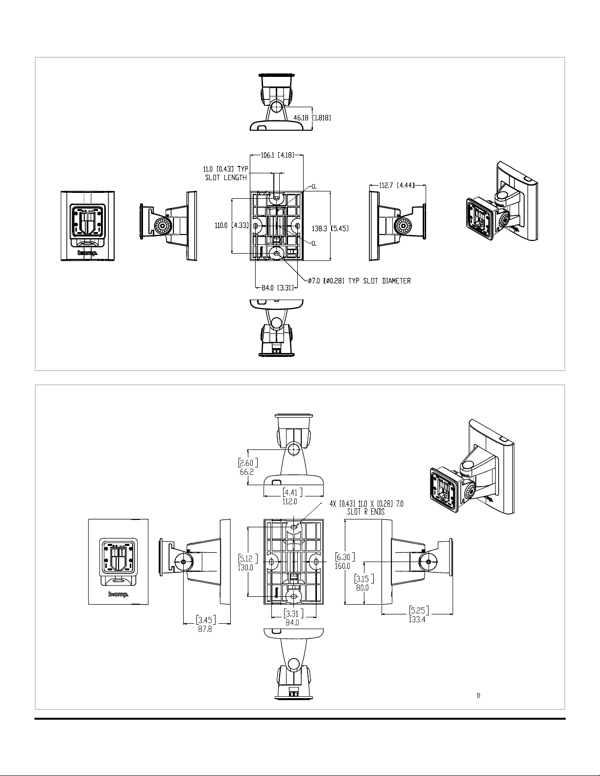
TECHNICAL DRAWINGS - CLICKMOUNT PAN-TILT BRACKET
CMX-SM
(ts EX-S6)
CMX-LG
(ts EX-S8, EX-S10 & EX-S10SUB)
Hardware: 1/4-20 or 6mm screw for attachment,
Backplate will accept typical 1/2" or 13mm socket (18mm OD)
Hardware: 1/4-20 or 6mm screw for attachment,
Backplate will accept typical 1/2" or 13mm socket (18mm OD)
page 8 Installation and Operation Guide Desono EX-S
Page 9

TECHNICAL DRAWINGS - U-BRACKETS
EXUB-S6
(ts EX-S6)
EXUB-S8
(ts EX-S8)
EXUB-S10
(ts EX-S10 & EX-S10SUB)
2x 11.0 [0.43] X 41.0 [1.61]
SLOT R ENDS
4x 8.5 [0.33] X 38.5 [1.52]
SLOT R ENDS
Desono EX-S Installation and Operation Guide page 9
2x 11.5 [0.45] X 8.5 [.33]
SLOT R ENDS
Page 10

CONTACT US
Email: support@biamp.com
Web: support.biamp.com
Warranty: biamp.com/legal/warranty-information
A: 9300 S.W. Gemini Drive Beaverton, OR 97008 USA W: www.biamp.com
09FEB2022
 Loading...