

Page 1
®
Vocia
ELD-1
Operation Manual
January 2013
Biamp Systems, 9300 SW Gemini Drive, Beaverton, Oregon 97008 U.S.A. (503) 641-7287 www.biamp.com
Page 2
IMPORTANT SAFETY INSTRUCTIONS
IMPORTANT SAFETY INSTRUCTIONS
1) Read these instructions.
2) Keep these instructions.
3) Heed all warnings.
4) Follow all instructions.
5) Do not use this product near water.
6) Clean only with dry cloth.
7) Do not block ventilation openings.
Install in accordance with the
manufacturer’s instructions.
8) Do not install near any heat
sources such as radiators, heat
registers, stoves, or other product
(including amplifiers) that produce
heat.
9) Do not defeat the safety pur
the grounding-type plug. A grounding
type plug has two blades and a third
grounding prong.
The third prong is provided for your
safety. If the provided plug does not
fit into your outlet, consult an
electrician for replacement of the
obsolete outlet.
pose of
10) Protect the power cord from being
walked on or pinched particularly at plugs,
convenience receptacles, and the point
where they exit from the product.
11) Only
spec
12) Use only with equipment rack, cart,
stand or table designed to provide adequate
mechanical strength, heat dissipation and
securement to the building structure.
When a cart is used, use
caution when moving the cart
and product combination to
avoid injury from tip-over.
13) Unplug this product during lightning
storms or when unused for long periods of
time.
14) Refer all servici
personnel.
product has been damaged in any way, such
as power-supply cord or plug is damaged,
liquid has been spilled or objects have fallen
into the product, the product has been
exposed to rain or moisture, does not
operate normally, or has been dropped.
use attachments/accessories
ified by the manufacturer.
ng to qualified service
Servicing is required when the
WARNING - To reduce the risk of fire or electric shock, do not expose this product to rain or
moisture.
WARNING - This product employs Safety Grounding and must be connected to a MAINS
socket that is properly grounded to provide a protective earthing connection.
Disconnect Device - The MAINS plug is used to disconnect MAINS power and must be
installed near the equipment and remain readily accessible.
Explanation of safety related symbols - Product labeling
use the internationally recognized symbols defined below to note safety messages.
Lightning Bolt: Hazardous Live voltages present when this unit is in operation. Do
not touch terminals marked with this symbol while the unit is connected to live power.
Exclamation Point: Replace components (i.e. fuses) only with the values specified by
the manufacturer. Failure to do so will compromise safe operation of this uni
and the operation manual may
t.
2
Page 3

TABLE OF CONTENTS
VOCIA END OF LINE DEVICE (ELD-1) FEATURES ..................................................... 4
SETUP AND USE ...................................................................................5-6
Network Connection ................................................................................. 5
Speaker Line Connector ..............................................................................6
INSTALLATION ....................................................................................... 7
SPECIFICATIONS & BLOCK DIAGRAM ................................................................ 8
WARRANTY ..........................................................................................9
FCC COMPLIANCE ..................................................................................10
EC DECLARATION ................................................................................... 11
EU ROHS COMPLIANT. . . . . . . . . . . . . . . . . . . . . . . . . . . . . . . . . . . . . . . . . . . . . . . . . . . . . . . . . . . . . . . . . . . . . . . . . . . . . . . 12
3
Page 4
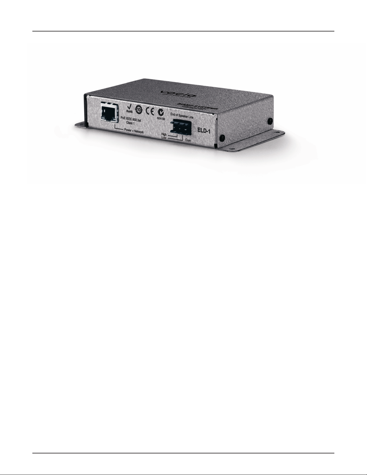
VOCIA END OF LINE DEVICE (ELD-1)
The Vocia® End of Line Device (ELD-1) is a networked safety device for use with Vocia output devices. Supported models include the complete
line of Vocia ampliers and the Emergency version of the Vocia Output 4 device (VO-4e). The ELD-1 is an integral part of compliant voice
evacuation and mass notication systems. The ELD-1 tests speaker line integrity between the output device and the ELD-1. The device can be
surface mounted and utilizes IEEE-compliant Power over Ethernet (PoE) technology. The ELD-1 is compatible with both constant voltage and
low impedance systems and does not rely on the speaker line as a power source.
FEATURES
• Line monitoring
• Looks for inaudible signal from the Vocia output device
• Reports shorts or open conditions on the speaker line
• Surface mountable
• Power and data over a single Ethernet cable
• Status LED
• CE marked and RoHS compliant
• Covered by Biamp Systems’ ve-year warranty
4
Page 5

ELD-1 SETUP AND USE
Setup and Use
The Vocia software provides an intuitive interface for conguration, DSP equalization, and programming of the ELD-1. The information supplied
by this manual relates to physical connections and assignment. For more details on software setup, please consult the Vocia Help File.
Device ID
In contrast to most other devices in the Vocia product range, the ELD-1 does not require setting a Device ID.
Network Connection
Connect the device to a PoE-compliant network and at the end of the speaker line.
An 802.3af compliant PoE-enabled network switch or PoE midspan adapter must be used to power the ELD-1. The maximum distance be-
tween any unit and an Ethernet switch is 328 feet (100 meters) when using copper cabling. Additional Ethernet switches and/or ber-optic
cable can be used to further extend distances between units on a network.
ELD-1 devices are designed to be placed on the Vocia CobraNet network. If other network trafc shares an Ethernet switch with the Vocia
network a managed switch should be used with separate VLANs. The following diagrams illustrate valid network connections for the ELD-1.
Ethernet switch
with PoE
ELD-1
Ethernet switch
without PoE
ELD-1
PoE
injector
AC Power
Amber LED Green LED
Off Flashing green Unit is receiving monitoring Tones from speaker line. Ethernet link has been established between the
Switch, PoE Midspan or Injector device.
Off Off Unit is not powered.
Unit is powered via Midspan PoE injector and is receiving monitoring Tones from speaker line but has
no Ethernet Link to its associated Switch Port.
On Off Unit is powered via Midspan PoE injector and is not receiving monitoring Tones from speaker line.
There is no Ethernet Link to its associated Switch Port.
On Flashing green Unit is not receiving monitoring Tones from speaker line. There is a speaker line fault.
5
Page 6

ELD-1 SETUP AND USE
High
Speaker Line Connector
A plug-in barrier-strip connector on the ELD-1 connects the device to the end of the speaker line. The device needs to be connected to an
appropriate monitoring point on the speaker cable—typically after the last speaker on the run. Connect the speaker line between the Com
pin and the appropriate Low or High pin as dened in the table below.
Amplier Power
Speaker Circuit Less than 100 Watts 100 Watts or greater
4Ω Low Low
6Ω Low Low
8Ω Low Low
25 Volt Low Low
70 Volt Low Low
100 Volt Low High
Note that for circuits connected to the Low terminal the ELD-1 presents a 0.5 Watt load to a 70V circuit and a 1 Watt load to a 100V circuit.
End of Speaker Line
Com
Low
Output Fault Detection
The Amplier monitors (supervises) for faults on speaker connections using a combination of multiple out-of-band (inaudible) high frequency
tones.
For end-of-line detection, one or more (up to 15 maximum) ELD-1 units can be connected to the speaker line. To ensure correct operation of fault
detection it is necessary to follow these guidelines:
• Recorded audio messages or audio content with continuous or swept tonal components (e.g. alert tones) and any content with
signicant high frequency harmonic content should be band limited (>24dB/octave) at 15 kHz during recording. Note that program
content that is distorted due to poor recording techniques may contain excessive high frequency harmonics.
• Signal level adjustments within a Vocia system should be set so as to minimize clipping. Severely clipped signals may also affect
the out-of-band fault detection tones.
• The use of speaker cables that inherently attenuate high frequencies is not supported (e.g. screened cables). Speaker cables must
maintain frequency response to the end of line of less than -3dB @ 20kHz at with respect to 1kHz.
• Speaker cables longer than 500 feet may prevent correct operation of ELD and Ground Fault monitoring capabilities. An advantage
of Vocia is that ampliers may be easily distributed close to speakers, thereby minimizing long runs of expensive and potentially
lossy speaker cable.
• Highly capacitive speaker lines or loads may prevent correct operation of the ELD detection system.
• Legacy monitored speaker circuits that use capacitors and resistors or similar methods must have all legacy monitoring circuitry
removed for correct operation of the ELD detection system.
• For EN 54-16 compliance, one or more ELD units must be tted. End of Line detection must be enabled in the Vocia software.
Fault Indication
When a fault is detected on the speaker line or amplier channel, the lower left LED on the RJ-45 socket will illuminate Amber and remain
on until the fault is resolved. Providing a valid PoE power source and Ethernet connectivity is available the ELD-1 the solid amber indicator
can be used to physically identify the ELD-1 that is reporting an issue.
6
Page 7

ELD-1 INSTALLATION
Installation
The ELD-1 may be mounted in a rack or on a wall using four screws at the end of the anges or two screws in the keyholes on the rear.
Please install the unit away from heat sources, such as vents and radiators, and in rooms with adequate ventilation. Do not exceed the
maximum operating temperature of 32-113 degrees F (45°C).
An ELD-1 should be connected at the end of every speaker line that is to be monitored. The diagram below shows the appropriate connection
to the speaker wire and the network. In EN54-16 compliant systems the ELD-1 must be connected to a compliant Ethernet switch that is
backed by an uninterruptible power supply (UPS).
Vocia Amplier with ELD-1 Wiring Topology
VO-4e Emergency Output device with ELD-1 Wiring Topology
7
Page 8

ELD-1 SPECIFICATIONS
End of Line Device 1 SPECIFICATIONS
Speaker Line Input Configuration:
Connection:
Power:
RJ45 with shielded Ethernet/PoE
cable (CAT5, CAT5e, CAT6 or CAT7)
End of Line Device 1 BLOCK DIAGRAM
Balanced and Floating
(transformer coupled)
802.3af (PoE) Class 1
Overall Dimensions:
Height:
Width:
Depth:
Ambient Operating
Temperature Range:
Compliance:
1.06 inches (27mm)
6.0 inches (153mm)
3.07 inches (78mm)
32-113 degrees F (0-45 degrees C)
RoHS directive
CE marked
8
Page 9

ELD-1 WARRANTY
BIAMP SYSTEMS IS PLEASED TO EXTEND THE FOLLOWING 5-YEAR LIMITED WARRANTY TO THE ORIGINAL PURCHASER OF
THE PROFESSIONAL SOUND EQUIPMENT DESCRIBED IN THIS MANUAL
1. BIAMP Systems warrants to the original purchaser of new products that the product will be free from defects in material and
workmanship for a period of 5 YEARS from the date of purchase from an authorized BIAMP Systems dealer, subject to the
terms and conditions set forth below.
2 If you notify BIAMP during the warranty period that a BIAMP Systems product fails to comply with the warranty, BIAMP Systems
will repair or replace, at BIAMP Systems’ option, the nonconforming product. As a condition to receiving the benets of this warranty,
you must provide BIAMP Systems with documentation that establishes that you were the original purchaser of the products. Such
evidence may consist of your sales receipt from an authorized BIAMP Systems dealer. Transportation and insurance charges to
and from the BIAMP Systems factory for warranty service shall be your responsibility.
3. This warranty will be VOID if the serial number has been removed or defaced; or if the product has been altered, subjected to
damage, abuse or rental usage, repaired by any person not authorized by BIAMP Systems to make repairs; or installed in any
manner that does not comply with BIAMP Systems’ recommendations.
4. Electro-mechanical fans, electrolytic capacitors, gooseneck microphones, cords connecting handheld microphones, hard-drives,
displays, and normal wear and tear of items such as paint, knobs, handles, keypads and covers are not covered under this warranty. All server-based devices are warranted for 3 years only.
5. This warranty is in lieu of all other warranties, expressed or implied. Biamp Systems disclaims all other warranties, expressed or
implied, including, but not limited to, implied warranties of merchantability and tness for a particular purpose.
6. The remedies set forth herein shall be the purchaser’s sole and exclusive remedies with respect to any defective product.
7. No agent, employee, distributor or dealer of Biamp Systems is authorized to modify this warranty or to make additional warranties
on behalf of Biamp Systems. Statements, representations or warranties made by any dealer do not constitute warranties by Biamp
Systems. Biamp Systems shall not be responsible or liable for any statement, representation or warranty made by any dealer or
other person.
8. No action for breach of this warranty may be commenced more than one year after the expiration of this warranty.
9. Biamp systems shall not be liable for special, indirect, incidental, or consequential damages, including lost prots or loss of use
arising out of the purchase, sale, or use of the products, even if BIAMP Systems was advised of the possibility of such damages.
013013585.0263.90D
9
Page 10

FCC COMPLIANCE
FCC NOTICE - CLASS B DIGITAL DEVICE
NOTE: This equipment has been tested and found to comply with the limits for a Class B digital device,
pursuant to Part 15 of the FCC Rules. These limits are designed to provide reasonable protection against
harmful interference in a residential as well as in a commercial installation. This equipment generates, uses and
can radiate radio frequency energy and, if not installed and used in accordance with the instructions, may cause
harmful interference to radio communications. However, there is no guarantee that interference will not occur in a
particular installation. If this equipment does cause harmful interference to radio or television reception, which can
be determined by turning the equipment off and on, the user is encouraged to try to correct the interference by
one or more of the following measures: 1) Reorient or relocate the receiving antenna, 2) Increase the separation
between the equipment and receiver, 3) Connect the equipment into an outlet on a circuit different from that to
which the receiver is connected or 4) Consult the dealer or an experienced radio/TV technician for help.
10
Page 11

COMPLIANCE
DoC VELD201003!
EC Declaration of Conformity
Biamp Systems Corporation, as manufacturer having sole responsibility, hereby
declares that the following described product complies with the applicable provisions of
the DIRECTIVES below except as noted herein. Any alterations to the product not
agreed upon and directed by Biamp Systems Corporation will invalidate this declaration.
Product Model
Product Description
Applicable EC Directives
LVD Directive (2006/95/EC) Safety EN 60065:2002
EMC Directive (2004/108/EC) Emissions EN 55103-1:1996, Environment E2
Immunity EN 55103-2:1996
Special Considerations for Product Environment or Compliance
Use only CE marked Power over Ethernet (PoE) device.
Shielded cabling must be used for system connections.
Technical Construction File, Location and Contact
Biamp Systems Corporation phone: (503) 641.7287
9300 S.W. Gemini Drive fax: (503) 626.0281
Beaverton, OR USA 97008 e-mail: compliance@biamp.com
Authorized Representative: Larry Copley, Compliance Engineer
: Vocia® ELD-1
: End of Line Device for monitoring Speaker Circuit
: Applicable Harmonized Standards:
:
:
Authorized Signature:
Issued: March 2010
11
Page 12

COMPLIANCE
EU RoHS COMPLIANT
This Biamp product, including all attendant cables and
accessories supplied by Biamp, meets all requirements of EU
Directives 2002/95/EC of January 27, 2003, and 2005/618/EC
of August 18, 2005, the EU RoHS Directives. An EU RoHS
Materials Content Declaration document may be obtained at
www.biamp.com
(This information is presented to comply with the requirements of Chinese law SJ/T11363-2006)”
有害物质表
Biamp Systems Corporation
行结束监视器 (End of Line Monitor)
ELD-1
部件名称
设备机箱(Equipment Chassis)
插拔式接线端子 (Plug-in Terminal Blocks)
光盘(CD ROM)
手册和其他书面文档 (Manual and Paper Documents)
包装箱和所有包装材料 (Box and Packing Materials)
有毒有害物质或元素
Pb 铅 Hg
X O X O O O
O O O O O O
O O O O O O
O O O O O O
O O O O O O
汞
Cd
镉
Cr+6
六价铬
PBB PBDE
0:表示该部件所有均质材料中的这种有毒有害物质低于 SJ/T11363-2006 的限制要求.
X:表示该部件中至少有一种均质材料所含的这种有毒有害物质高于 SJ/T11363-2006 的限制要求.
在电触头和(或)镀镉所含的均质材料中,镉及其化合物的含量可以超过 0.01%,但欧盟指令 91/338/EEC(根据欧盟指令
76/769/EEC)限制销售和使用某些危险物质和制剂部分中所禁止的用途除外
在以下一种或多种物质所含的均质材料中,铅及其化合物的含量可以超过 0.1%:
1) 电子元器件中玻璃内所含的铅
2) 铅在钢材中是作为一种合金元素,含量可达 0.35%
3) 铅在铝材中是作为一种合金元素,含量可达 0.4%
4) 铅在铜材中是作为一种合金元素,含量可达 4%
5) 高熔点类焊料中的铅(即铅料合金,铅含量超过 85%)
6) 电子陶瓷部件内的铅
7) 由两种以上元素组成的焊料中所含的铅,用于连接针脚和微处理器包装,其中
铅的含量超过 80% 但低于 85%
8) 顺应针连接系统内的铅
9) 倒装芯片封装中半导体芯片及载体之间形成可靠连接所用焊料中的
在正常使用情况下,中国环保使用期限为 10 年,条件是:
• 环境温度为 0-40C (32-104°F)
• 湿度为 0-95%,无凝结
• 海拔高度为 0-10,000 英尺
• 气流不受阻碍
• 没有水或其他液体进入任何部件
• 电源为 IEEE 802.3af PoE
• 部件没有损坏(损坏部件应立即修理)
• 由工厂授权人员使用批准的材料进行所有维修
12
 Loading...