

Page 1
Desono™
DX-IC Ceiling Loudspeakers
Installation & Operation Guide
Models
DX-IC4LP
DX-IC4
DX-IC6
DX-IC6-B
DX-IC6LP
DX-IC6LP-TAA
DX-IC8
DX-IC10
DX-IC10SUB
PRODUCT INFORMATION
Desono DX Ceiling Loudspeakers are engineered and manufactured to be rugged
and are carefully packed in sturdy cartons. However, it is wise to thoroughly
inspect each unit after it has been removed from the packaging, as damage could
occur during shipping.
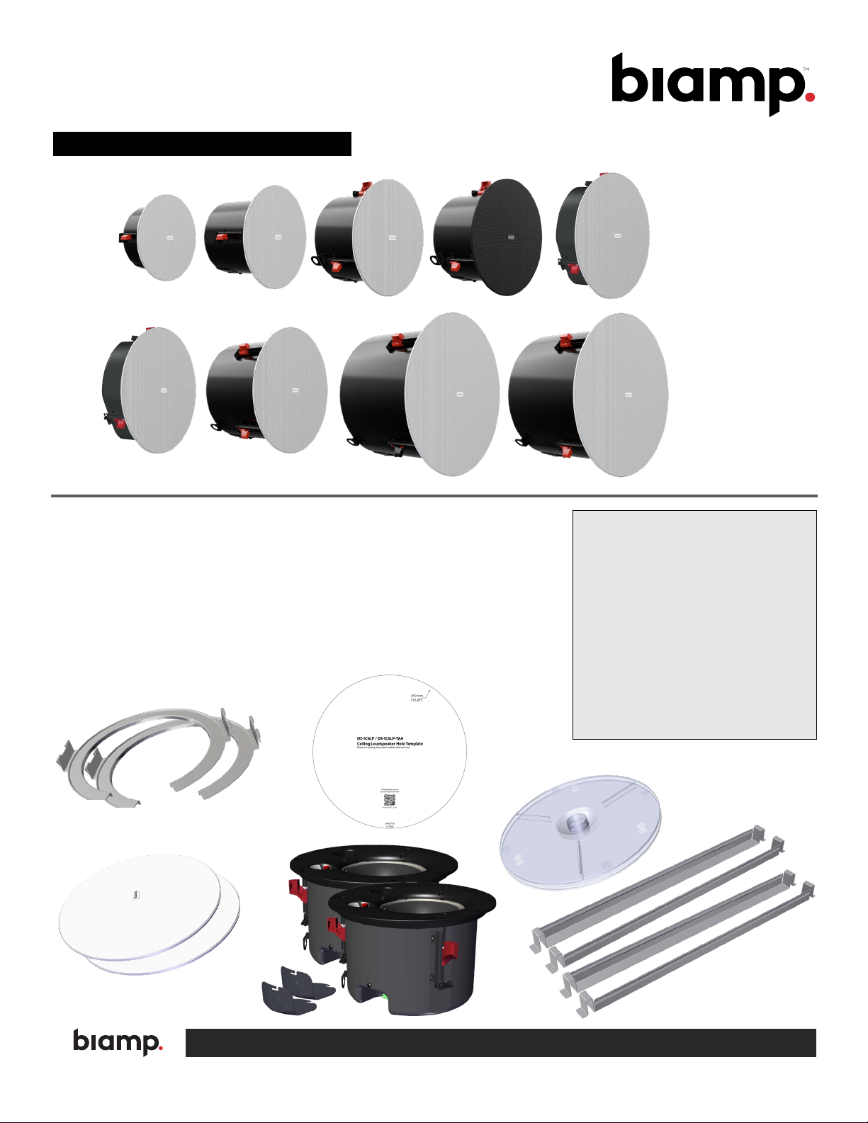
All DX ceiling loudspeakers are shipped in pairs. Below is a representation
of what is included. The tile rails for the DX-IC6LP look slightly different. The
DX-IC6LP-TAA is made in the USA, contains the same elements, and is installed
the same as the DX-IC6LP.
Box Contents:
DX-IC Models:
• Ceiling loudspeakers and covers (2)
• Grilles (2)
• C-ring support plates (2)
• Cutout template (1)
• Paint masks (2)
• 24" (610 mm) Tile bridge rails (4)
• Not Shown - Cable clamps (2),
Euroblock connectors (2),
Documentation
A: 9300 S.W. Gemini Drive Beaverton, OR 97008 USA W: www.biamp.com
Page 2

PRODUCT REPRESENTATION
Safety Cable
Mounting Point
Adjustable
Spring Clamps
Paint masks are shipped on the loudspeakers. You
can leave the masks on if the loudspeakers need to be
installed before the ceiling is nished. After installation,
cover the 3 screwdriver access holes in each with painter's
tape before painting. Once the ceiling is nished, remove
the paint masks, tighten in the ceiling if necessary, and
continue the installation.
Tap / Low-Impedance
Switch
Tools Needed
• Standard Phillips head screwdriver
• Small at screwdriver
• Wire stripper
• Conduit punch and cutter (for conduit
installations)
Grille
Grille
Tether
(Plug)
DX-IC6 Model shown
Mounting Point
Retention
Safety Cable
Cover
Screws
Back Can
Euroblock
Connector
Adjustable
Spring Clamps
Euroblock
Connector
Safety Cable
Mounting Point
Conduit Cover
Conduit
Knockouts
Conduit
Knockouts
NOTE: The installer is responsible for
Conduit Cover
sourcing the proper safety cable to meet
all applicable local building codes and
standards.
DX-IC6LP, DX-IC6LP-TAA
RIGGING AND ELECTRICAL SAFETY
IMPORTANT: The loudspeakers described in this manual are
designed and intended to be mounted to diering building
surfaces using a variety of rigging hardware, means and
methods. Installation of loudspeakers should only be performed
by trained and qualied personnel. All electrical connections
must conform to applicable city, county, state, and national
(NEC) electrical codes.
. DANGER: It is possible to experience severe electrical shock
from a power amplier. Always make sure that all power
ampliers are in the "OFF" position and unplugged from an AC
Mains supply before performing electrical work.
IMPORTANT: Refer to the sections on installation and
connections later in this manual for additional information on
rigging and electrical safety.
page 2 Installation and Operation Guide Desono DX-IC
IMPORTANT: Please review the safety guide accompanying
this product and these installation instructions prior to
installing this loudspeaker.
CAUTION: Installation of Biamp loudspeakers should only be
performed by trained and qualied personnel. It is strongly
recommended that a licensed and certied professional
structural engineer approve the mounting. Severe injury and/
or loss of life may occur if this product is improperly installed.
DANGER: It is advised that a safety cable be secured to a
suitable load-bearing point separate from the primary
loudspeaker mounting point, with as little slack as possible so
as not to develop undue kinetic force if the primary mount
were to fail.
IMPORTANT: This loudspeaker is approved for use in plenum
air handling spaces.
Page 3

INSTALLATION
The DX ceiling loudspeaker family is designed to be installed with or without
above ceiling access in drop ceilings. Prewiring and installation of optional New
Construction Brackets (SPA-NCxxx) allows DX-IC loudspeakers to be installed
in new drywall ceilings. DX-IC4, DX-IC4LP, and DX-IC6 loudspeakers can be
mounted in larger cutouts using optional ceiling trim rings (SPA-TRxxx).
Once the loudspeaker is mounted, rotate the face-mounted tap switch to select
the appropriate tap setting before any audio is passed through the loudspeaker.
Do not change the setting on the tap switch while the loudspeaker is in use.
Installation in drop (suspended) ceiling (typical)
1. Run wires to the loudspeaker locations.
2. Remove the ceiling tile and use the template to cut a hole in the center of
the tile. Remove any debris from around the hole.
3. Place the tile rails on the grid and t the C-ring tabs onto the rails.
DX-IC6LP only - secure C-Ring to rails with screws (see detail below)
4. Reinstall the ceiling tile and align C-ring with the opening.
2
NOTE: All electrical installation
connections for loudspeaker
lines are subject to all
applicable governmental building and
re codes. The selection of appropriate
electrical hardware to interface with the
loudspeaker lies solely with the
installation professional. Biamp
recommends that an appropriately
licensed engineer, electrician, or other
professional identify and select the
appropriate conduit, ttings, wire, etc. for
the installation.
DX-IC6 template shown
3
4
DX-IC6LP Only
Installation in a drop (suspended) ceiling with conduit
Prepare the ceiling tile as shown above. Access to the loudspeaker through an adjacent tile space is necessary to install
the cover after the unit is installed in the ceiling tile. The included wiring cover has knockouts on the side and top (1/2" NPT
(21.34mm), M20 (20.0mm), and PG13.5 (20.4mm)). Conduit fittings are not included. Use flexible conduit close to the
loudspeaker to make alignment and connections easier. Run wires and conduit to the loudspeaker locations.
NOTE: DX-IC4LP has only one knockout on the side to maintain a low profile. Conduit use may be required for some plenum
spaces and should also be used in damp spaces. Using input covers with conduit wiring will comply with the City of Chicago
requirements.
Desono DX-IC Installation and Operation Guide page 3
Page 4

INSTALLATION (continued)
IInstallation Connections and Wiring
The cover acts as a strain relief for wiring connections.
5. Remove one of the knockouts from the cover and install the cable clamp.
5
6. Thread the cable or wires through the clamp and wire the euroblock
connector as shown. Pay special attention to the labeled polarity.
Loudspeakers may be daisy-chained by using the second set of terminals.
IMPORTANT: Use the provided cable
clamp fitting to secure the wiring to
prevent accidental removal of the
euroblock connector if the wires are
pulled.
Install a cable clamp fitting in one of
the knockouts and run cable through
before wiring the connector. Tighten
the clamp after the cover is installed
to secure the wires.
6
In from the amplifier or
previous loudspeaker,
terminals 1[+] & 4[–]
Spring clamps
moved down
(Optional)
Out to the next loudspeaker,
terminals 2[+] & 3[–]
DX-IC6LPs
(only)
Installed
euroblock
connector
Terminal
Socket
page 4 Installation and Operation Guide Desono DX-IC
Page 5

INSTALLATION (continued)
7. Install the cover as shown.
Typical DX-IC: Install cover (a-b), secure by tightening circled screws (c).
DX-IC6LPs only: Insert cover in slots (d) and secure with thumbscrew (e).
8. Tighten the clamp screws around the cable to provide strain relief.
7
a
b
c
d e
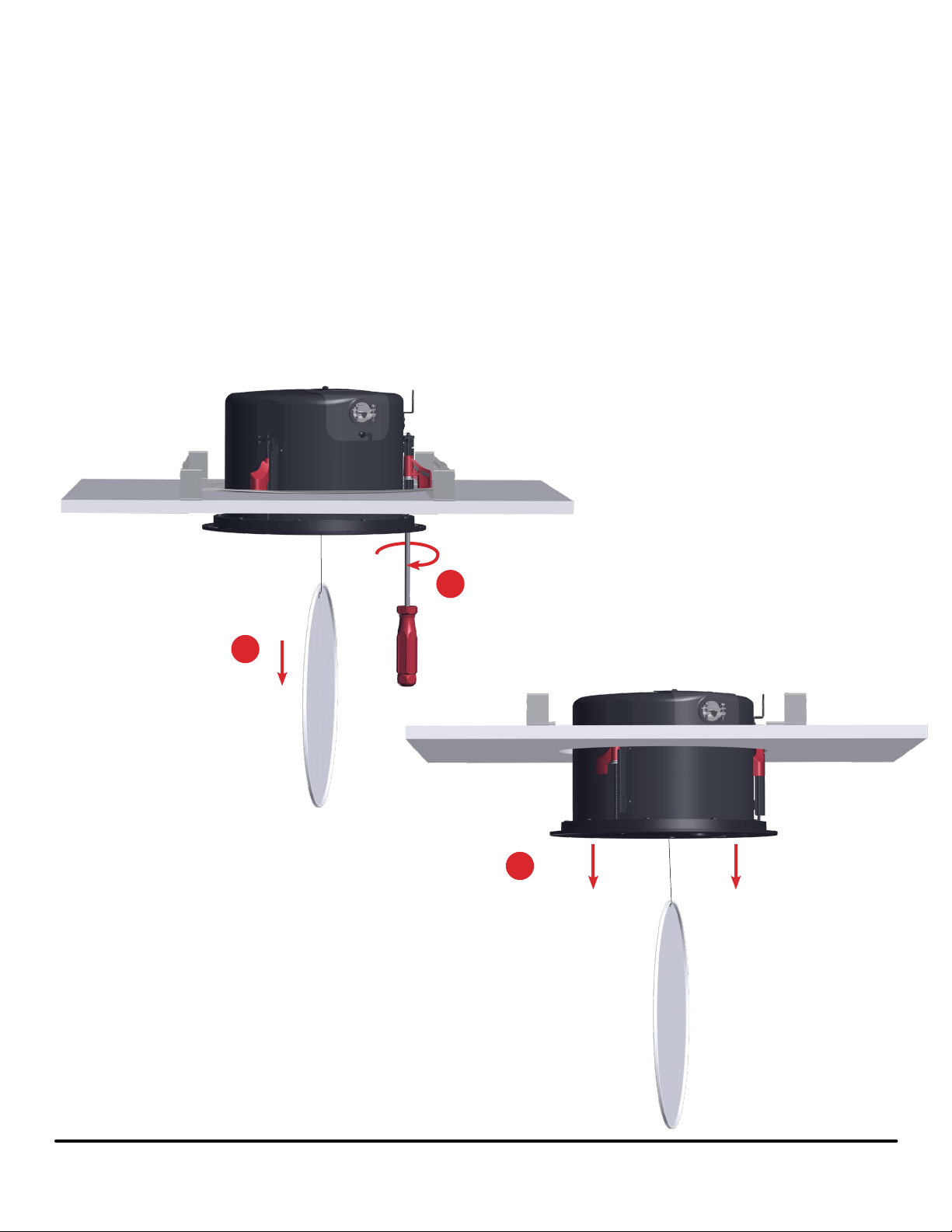
9. If necessary, adjust spring
clamps (with a Phillips head
screwdriver) to allow slightly
more space between the rim and
the bottom of the spring clamp
than the depth of the ceiling tile
and C-ring together. The clamps
should all be at the same height.
10. Secure a safety cable to the
seismic safety tab. Make the
cable as short as possible.
Attach the cable to a secondary
structural point directly above the
seismic safety tab to minimize
impact force and swing in the
event of a ceiling failure.
*NOTE: This can also be done
after installing the unit if there is
access in the ceiling.
8
10
Safety Cable
9
Desono DX-IC Installation and Operation Guide page 5
Page 6

INSTALLATION (continued)
11. Rotate loudspeaker clockwise as you insert it into the hole. This
collapses the clamps as they move up through the hole (a-d). Once past
the ceiling the clamps will spring out and prevent it from falling.
IMPORTANT: The loudspeaker must be fully supported until the clamps
have moved above the ceiling and returned to their "out" position.
12. Push the loudspeaker up with the rim against the ceiling tile and tighten
the screws (opposing sides rst), to lower the spring clamps to secure it
in the ceiling.
NOTE: Do not overtighten. If the ceiling tile is deformed, the grille may
not stay on.
11
b
c
11
a
d
IMPORTANT: For closed ceiling applications all
connections (wiring and safety cable) must be
made with the input cover installed before inserting the
unit in the ceiling.
12
page 6 Installation and Operation Guide Desono DX-IC
Page 7

INSTALLATION (continued)
Set Power Tap
13. Set tap switch by rotating knob to the desired setting. Both the DX-IC6 and
DX-IC6LP are shown. The DX-IC6LP models have 6 tap settings.
13
DX-IC (typical) DX-IC6LP
Install Grille
14. Fully insert the grille plug attached to the grille's safety tether into the empty
hole in the loudspeaker face.
15. Place grille against the face. The magnets will hold it in place. Make sure
the grille is fully seated on the loudspeaker face.
14
15
Grille Plug
(Safety tether)
Desono DX-IC Installation and Operation Guide page 7
Page 8

INSTALLATION OPTIONS
Installation in a drywall [sheet rock] ceiling
Adequate distance above the drywall must be available to accommodate the
depth of the back can.
1. The appropriate size of new construction brackets (SPA-NCxxx) should be
utilized and secured to the ceiling structure (see below).
NOTE: Use a stretched string or laser to align the brackets, rather than
aligning to the truss.
2. Run wiring to each bracket location allowing sucient length to allow for
connection to the back can.
3. A safety cable should be attached to the structure with sucient length to
allow for connection to the back can.
4. Install the drywall and cut out the hole inside the bracket. Allow wires and
cable to hang through the hole or be accessible in the ceiling.
5. After the ceiling is nished, install the loudspeaker (steps 5-12 of this guide
- pages 4-6). Screwing down the spring clamps will secure the loudspeaker
in the ceiling.
6. Finish the installation by setting the tap switch and installing the grille
(steps 13-15 - page 7).
Model Fits
SPA-NC300 DX-IC4, DX-IC4LP
SPA-NC400 DX-IC6
SPA-NC500 DX-IC8, DX-IC6LP
SPA-NC600 DX-IC10, DX-IC10SUB
Install bracket and drywall or sheet rock
page 8 Installation and Operation Guide Desono DX-IC
Page 9
LOUDSPEAKER REMOVAL
If there is a wired conduit connection to the loudspeaker, disconnect it first by
removing the cover and terminal block.
Follow steps below to remove the loudspeaker from the ceiling.
1. Pull the grille down until the magnets let go, and let it dangle from the
tether.
2. Loosen the spring clamps by turning each screw counter-clockwise until it
stops. The spring clamp will travel up the screw and turn against the can.
Repeat for all screws.
CAUTION: The loudspeaker must be fully supported as the spring clamps
are turned to prevent it from falling as the spring clamps move up and in.
3. Remove the loudspeaker from the ceiling. Detach the safety cable (and
wiring, if it wasn't removed previously).
2
1
3
Remove loudspeaker from ceiling
Desono DX-IC Installation and Operation Guide page 9
Page 10

DESONO CEILING ACCESSORIES
A variety of ceiling accessories are available to aid differing types of installations
and applications. A complete reference guide noting part numbers and what they
fit is available on the website as well as full installation guides for each type.
SPA-GRBxxx Black accessory grilles
SPA-GHHxxx High humidity grilles
SPA-NCxxx New construction bracket for drywall
or sheet rock ceilings.
SPA-RAIL48 48" tile railes for installation in ceilings
using 48" tiles
SPA-TRxxx Trim rings to allow DX-IC4, DX-IC4LP,
or DX-IC6 models to fit in oversize
holes
page 10 Installation and Operation Guide Desono DX-IC
Page 11

PAINTING INSTRUCTIONS
The grille may be painted to match room decor. Do NOT
paint the grille when on the loudspeaker. Remove the scrim
material (cloth) prior to painting.
1. Purchase a citrus-based label/adhesive remover
spray (PRF Label O®, Goo Gone® or similar).
2. Pull the grille away from the face. Remove the tether
plug from the face, do not bend the grille.
3. Gently pry the logo from the grille using a non-metallic
tool, or fully mask the logo. Use a sharp knife to
trim the masking material close to the edges of the
masked areas.
4. Remove the grille cloth (scrim material) by spraying all
of the fabric with the adhesive remover.
5. Wait a few minutes to allow the fabric to fully absorb
the spray.
6. Carefully peel o the grille cloth, taking care not to rip
or stretch the fabric.
7. Once the cloth and logo have been removed, some
glue residue may remain on the grille. If so, apply
additional adhesive remover to remove the glue.
8. Thoroughly clean and degrease the grille before
painting. Do not use a solvent (see Cautions above).
9. Paint the grille with several light coats of spray paint
at twice the recommended distance from the grille. Do
not clog the grille perforations with paint.
10. Allow the paint to fully dry and cure.
11. If necessary, reattach the grille cloth. Use a light coat
of simple spray adhesive. Avoid clogging the grille
perforations with any adhesive.
12. Press and smooth the cloth on the grille.
13. Reattach the tether plug.
14. Reattach the logo if required.
15. Attach the grille to the loudspeaker per the installation
instructions.
CAUTION: NEVER use abrasives, gasoline,
kerosene, acetone, methyl ethyl ketone (MEK),
paint thinner, harsh detergents or other chemicals on
the loudspeaker. These chemicals and agents may
permanently damage the nish. Some are also toxic
and highly ammable.
IMPORTANT: Do not bend or damage the grille on
removal or reinstallation.
IMPORTANT: Blocking the grille holes with paint or
getting any paint on the drivers or internal parts will
aect loudspeaker performance and void the warranty.
Desono DX-IC Installation and Operation Guide page 11
Page 12

CONTACT US
Email: support@biamp.com
Web: support.biamp.com
Warranty: biamp.com/legal/warranty-information
Safety & Compliance: biamp.com/compliance
A: 9300 S.W. Gemini Drive Beaverton, OR 97008 USA W: www.biamp.com
24OCT2023
 Loading...