

Page 1

ADVANTAGE® DDL12
Digital Delay Line
Operation Manual
®
5/5/98
Biamp Systems, 10074 S.W. Arctic Drive, Beaverton, Oregon 97005 U.S.A. (503) 641-7287 http://www.biamp.com
an affiliate of Rauland Borg Corp.
Page 2

DDL12
TABLE OF CONTENTS
Front & Rear Panel Features
Setup
Logic Inputs
RS-232 Control
Applications
Specifications & Block Diagram
Warranty
pg. 2
pgs. 3~5
pgs. 6 & 7
pgs. 8 & 9
pgs. 10 & 11
pg. 12
INTRODUCTION
The ADVANTAGE®
1-input by 2-output digital delay. Gain & delay settings are adjusted via
Windows
®
95 programming software, eliminating the need for front panel
Digital Delay Line is a programmable DSP-based
DDL12
controls or security codes, and providing a completely tamper proof unit. Up to
8 presets may be stored in non-volatile memory, and recalled via
programmable logic inputs. The DDL12 is covered by a five-year warranty.
features include:
DDL12
1-in/2-out DSP-based programmable dual-tap digital delay
♦
balanced input & outputs on plug-in barrier strip connectors
♦
variable input & output levels with metering & bypass mode
♦
broad delay range useful for room delay or driver alignment
♦
distance calculations & ‘automatic’ unity gain for easy setup
♦
48kHz sampling rate with 16-bit sigma delta converters
♦
64x oversampling A/D (in) & 128x oversampling D/A (out)
♦
eight non-volatile memory presets store/recall delay settings
♦
programmable logic inputs for remote control via switches
♦
no manual controls on chassis, to help prevent tampering
♦
controls & indicators provided by software graphic interface
♦
RS-232 serial port & Windows® 95 programming software
♦
incorporates
♦
marked and
♦
covered by Five-Year "Gold Seal" Warranty
♦
recommended grounding practices
AES
UL / C-UL
listed power source
1
Page 3
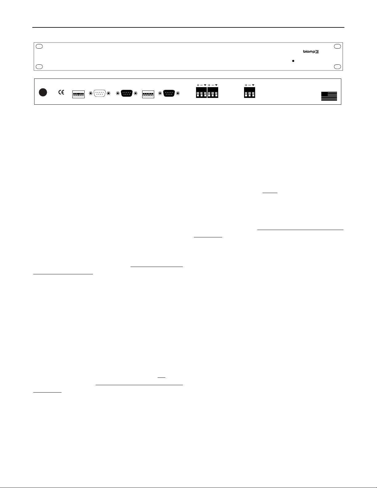
FRONT & REAR PANEL FEATURES
ADVANTAGE DDL12
Digital Delay Line
on
27V
~
50/60 Hz
10 watts
class 2 wiring
On Indicator:
3216842
1
device # serial port link port
last
2400
9600
19200
baud rate logic inputs
This red LED indicates power is applied to the unit.
The DDL12 provides no power switch. Power is applied by simply
plugging the wall-mount transformer into a proper AC outlet.
output 2 output 1
Baud Rate:
assigned a specific communications baud rate. Baud rates
available are 2400, 9600, & 19200 bps. The factory default is
9600 bps. Only one baud rate should be selected at a time, by
AC Power Cord:
The power transformer provides 27 Volts AC to
the DDL12, and is detachable via a 5-pin DIN connector. The
DDL12 has two internal ‘self-resetting’ fuses (there are no user
serviceable parts inside the unit). If the internal fuses blow, they
will attempt to re-set after a short period. However, this may be an
indication that the DDL12 requires service.
raising the corresponding switch. The two switches on the far right
are not used. The switch on the far left (labeled ‘last’) is used
when connecting multiple devices in a ‘Link Port to Serial Port’
configuration (see Link Port). From the factory, the ‘last’ switch is
up. When connecting multiple devices, the ‘last’ switch must be
switched down on all devices except the final (‘last’) device in the
system (the device with no Link Port connection).
Device #:
assigned a specific device number. Up to 64 different device
numbers (0~63) may be assigned to allow RS-232 control of
multiple ADVANTAGE
factory, the DDL12 is assigned Device # 1.
This 6-gang DIP switch allows the DDL12 to be
Logic Inputs:
®
products in a common system. From the
logic inputs for controlling the DDL12 via contact-closures (see
Logic Inputs on pg. 6). Logic Inputs have the following pin
assignments (right-to-left & top-to-bottom):
Inputs 1~8;
95
using the PC Control Software and serial cable provided with the
DDL12 (see Setup on pg. 4). From the factory, Logic Inputs 1~8
are programmed to recall presets 1~8 respectively.
Input:
line-level input. For balanced connection, wire high to (+), low to
(-), & ground to (
and ground to both (-) & (
RS-232 control (see Setup on next page).
Output 1 & Output 2:
Serial Port:
This 9-pin Sub-D (male) connector provides an RS232 Serial Port for remote control via computer or third-party
controllers (see RS-232 Control on pg. 8). The Serial Port has the
following pin assignments (left-to-right & top-to-bottom):
not used;
Data (TxD) output;
Ground;
Pin 5)
output;
Pin 8)
Receive Data (RxD) input;
Pin 2)
Data Terminal Ready (DTR) output;
Pin 4)
not used;
Pin 6)
not used;
Pin 7)
not used. PC Control Software
Pin 9)
Pin 3)
Request To Send (RTS)
and a serial cable are provided for programming via Windows
(see Setup on pg. 3).
NOTE: The Serial Port can also transmit
Pin 1)
Transmit
®
commands received via the Logic Inputs (see Setup on pg. 4).
provide the two independently delayed balanced line-level outputs.
Link Port:
Port for RS-232 control of multiple ADVANTAGE
RS-232 Control on pg. 8). The Link Port of one device simply
connects to the Serial Port of the next device (and so forth). Link
cables are available as an option (Biamp #909-0057-00).
This 9-pin Sub-D (female) connector provides a Link
®
products (see
For balanced connections, wire high to (+), low to (-), and ground
to (
ý
(
when outputs are unbalanced. Output gain is adjusted via
NOTE:
software or RS-232 control (see Setup on next page).
ý
), leaving (-) unconnected. Signal level will be reduced by 6dB
All but the final device in a system should have its ‘last’ switch
down (see Baud Rate)
assignments (right-to-left & top-to-bottom):
Transmit Data (TxD) output;
2)
not used;
Pin 4)
used;
not used;
Pin 8)
. The Link Port has the following pin
not used;
Pin 1)
Receive Data (RxD) input;
Pin 3)
Pin 5)
Ground;
not used.
Pin 9)
not used;
Pin 6)
NOTE: The Link Port
Pin 7)
Pin
not
will also transmit commands received via the Logic Inputs (see
Setup on pg. 4).
input
BIAMP SYSTEMS
Portland, Oregon
an affiliate of
Rauland-Borg Corp.
DDL12
MADE IN U.S.A.
This 6-gang DIP switch allows the DDL12 to be
This 9-pin Sub-D (female) connector provides eight
Pins 1~8)
switch ground. Logic Inputs are programmed
Pin 9)
These plug-in barrier strip terminals provide a balanced
ý
). For unbalanced connection, wire high to (+),
ý
). Input gain is adjusted via software or
These plug-in barrier strip terminals
). For unbalanced connections, wire high to (+) and ground to
Logic
2
Page 4
SETUP
All DDL12 parameters are adjustable using the Windows® 95 'PC Control Software' and serial cable provided with the unit. The PC Control
Software provides programs for various ADVANTAGE® products, including the DDL12. The DDL12 program includes three different
control screens (Main, Logic Input & Button Definition & Configuration Options), which are described on the following pages. Once the
software is started (and Comm Port Configuration is set), the control screens are accessible through the drop-down menus at the top of the
opening screen. The Main screen appears whenever a DDL12 file is opened. Logic Input & Button Definition
screens are then available from the Configure DDL12 menu. The File menu provides functions such as open, close, save, etc. The
Settings menu recalls the Comm Port Configuration screen. The Window menu arranges the active product screens. The Help menu
explains the available adjustments. To install PC Control Software: Select ‘Run’ from Windows® 95 ‘Start’ menu, and enter A:\SETUP.
System Requirements: Windows® 95 with 8M of RAM & 2M of available hard disk space (serial port required for ‘on-line’ operation).
and Configuration Options
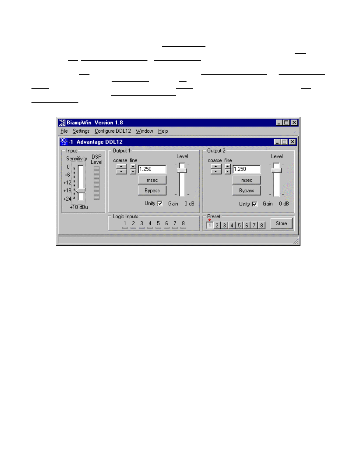
MAIN SCREEN
The Main Screen is used to adjust the DDL12 input/output levels & delay times, as well as to store & recall the eight memory presets
Adjustments are made with the computer mouse (or keyboard). Levels are adjusted by dragging the corresponding ‘faders’ up or down.
Input Sensitivity adjusts for the proper input signal peak reference level by providing up to 24dB of attenuation, adjustable in 1dB steps.
The DSP Level meter will display the corresponding input signal level. For best performance, adjust Input Sensitivity so the DSP Level
meter shows occasional peaks in the yellow area,
time is shown in the window, with adjacent buttons providing the up/down adjustments. Left-clicking coarse buttons will change the delay
time in 1 milli-second increments. Left-clicking fine buttons will change the delay time in 21 micro-second increments. Delay time may also
be entered directly into the window, but will be rounded to the nearest available setting. Left-clicking msec allows delay times to instead be
entered & calculated in terms of distance measurements (inches, feet, centimeters, or meters). Left-clicking Bypass temporarily sets delay
for that output to minimum, but has no effect on input/output gain settings. Level provides gain adjustment for that output, but the range
will be affected by the Input Sensitivity settings. Left-clicking Unity will link that output Level fader to the Input Sensitivity fader, maintaining
a constant unity gain setting through the DDL12. Left-clicking a Preset button will recall the corresponding preset from non-volatile
memory. Left-clicking the Store button will open a drop-down menu for storing current settings in any of the Presets 1~8. Logic Inputs are
strictly indicators of remote on/off activity at the Logic Inputs. The title bar across the top of the Main screen will indicate the Device #, the
custom Device Name, and the model of product being controlled. The PC Control Software can operate ‘off-line’ (with no product
connected) by opening a ‘new’ file for the desired product. The Device # for ‘off-line’ files is assigned sequentially as a negative number.
but never to the red (top).
Output 1 & Output 2 provide delay & gain adjustments. Delay
.
NOTE: Distances should be measured in terms of the difference between direct and delayed sound sources, with respect to the listene r
(i.e...direct source to listener = 200 feet; delayed source to listener = 20 feet; distance = 180 feet). Also, when sounds from the direct
source & delayed source reach the listener at roughly the same volume level, additional delay (approximately 10~30 milliseconds ) may be
added to the calculated delay time. This added delay will produce what is known as the ‘Haas Effect’, which gives the listener the
impression that all sound is emanating from the direct source. This added delay should be fine-tuned by ear to achieve the desired results.
3
Page 5

SETUP
LOGIC INPUT & BUTTON DEFINITIONS SCREEN
The Logic Input & Button Definitions screen is used to assign specific ‘recall preset actions’ to the Logic Inputs (and remote control
buttons). Logic Inputs allow remote control of preset selection via external circuits, such as switches, contact-closures, active driver
circuits, and/or ‘open-collector’ logic outputs (see Logic Inputs on pg. 6). From the factory, Logic Inputs 1~8 are programmed to recall
presets 1~8 respectively. However, using the Logic Input & Button Definitions screen, each Logic Input may be assigned differe nt ‘recall
preset actions’. Left-clicking on a numbered button will select that Logic Input to be defined. Left-clicking on Preset Actio n will open a
drop-down menu of the available recall preset actions. Left-clicking the desired recall preset action will then assign that action to the
currently selected Logic Input. Since Logic Inputs are controlled by switches, contact-closures, etc., each Logic Input may be assigned
certain recall preset actions to perform when the switch is ‘opened’, and different recall preset actions to perform when that same switch is
‘closed’. Left-clicking on Echo Character opens a drop-down menu, which allows the ‘echo’ character for the selected Logic Input to be
changed. This is the RS-232 ASCII character which will be transmitted via the Serial Port whenever that Logic Input is switched. From the
factory, no echo characters are assigned to Logic Inputs 1~8. Changing the echo character is used primarily for customizing remote
control commands amongst various RS-232 controlled products within a system (see RS-232 Control on pg. 8).
NOTE: Unlike other
remote controls, the DDL12 Logic Inputs do not include a ‘repeat’ function. Therefore, a Logic Input in an ‘opened’ or ‘closed ’ state will not
continuously repeat an echo character via RS-232
can still receive echo characters (via RS-232) from other ADVANTAGE
. Although the DDL12 does not accept infrared or wall-mount remote controls itself, it
®
products which are utilizing these types of remote controls. From
the factory, Remote Control Buttons have equivalent ASCII characters permanently assigned to them (see RS-232 Control on pg. 8).
Therefore, recall preset actions can be assigned to Remote Control Buttons in the same way they are assigned to Logic Inputs. Leftclicking on Clear opens a drop-down menu, which allows recall preset actions to be cleared from the selected Logic Input (or all Logic
Inputs). Left-clicking on Default opens a drop-down menu, which allows recall preset actions to be set back to the factory default for the
selected Logic Input (or all Logic Inputs). Left-clicking on Try It causes the recall preset actions currently assigned to the selected Logic
Input to be performed by the DDL12. Left-clicking on Help provides additional instruction. Left-clicking on Close will close the Logic Input
& Button Definitions screen.
4
Page 6

SETUP
CONFIGURATION OPTIONS SCREEN
The Configuration Options screen is used to select options which customize the operation of the DDL12. At the top of the Configuration
Options screen, the Serial Number and Firmware Version
(with no product connected) by opening a ‘new’ file for the desired product. The Serial Number and Firmware Version are not displayed for
‘new’ (‘off-line’) files. Left-clicking on Device Name allows a custom name to be given to the particular DDL12, by entering up to 30
characters of text. The Device Name will be stored in the DDL12 memory, and will be displayed on the title bar of the Main screen
whenever that DDL12 is accessed with the software. Double-clicking the Temperature window will allow the expected average air
temperature for the install location to be entered. Left-clicking degrees C allows temperature to be entered in either Celsius or Fahrenheit.
The resultant Velocity of Sound is then displayed underneath. The Power-up status section provides a choice of settings the DDL12 will
recall from memory each time power is cycled off & on. Left-clicking on Restore Defaults will set all Configuration Options back to their
factory defaults. Left-clicking Help provides additional instruction. Left-clicking Close will close the Configuration Options screen.
of the DDL12 will be displayed. The PC Control Software can operate ‘off-line’
5
Page 7

LOGIC INPUTS
Eight Logic Inputs are available on a rear panel 9-pin Sub-D (female) connector. Logic Inputs allow remote control of the DDL12 via
external circuits, such as switches, contact-closures, active driver circuits, and/or ‘open-collector’ logic outputs. From the factory, Logic
Inputs 1~8 are programmed to recall presets 1~8, respectively. However, each Logic Input may be assigned different ‘recall preset
actions’., using the PC Control Software and serial cable provided with the DDL12 (see Setup on pg. 4). Since Logic Inputs are controlled
by switches, contact-closures, etc., each Logic Input may be assigned two functions (one for switch ‘closed’ and one for switch ‘open’).
Logic Inputs have the following pin assignments (right-to-left & top-to-bottom
12345
6789
pin #1 = Logic Input 1
pin #2 = Logic Input 2
pin #3 = Logic Input 3
pin #4 = Logic Input 4
pin #5 = Logic Input 5
): Pins 1~8)
Logic Inputs 1~8;
pin #6 = Logic Input 6
pin #7 = Logic Input 7
pin #8 = Logic Input 8
pin #9 = ground
Pin 9)
Ground.
logic inputs
When nothing is connected to a Logic Input, an internal pull-up resistor keeps it at a ‘high’ idle state (+5.0 VDC). The Logic Input is
activated when its input goes ‘low’ (less than +0.8 VDC), and is de-activated when its input goes ‘high’ (greater than +2.4 VDC). A Logic
Input is controlled in one of three ways: 1) Use an NPN style ‘open-collector’ logic output from an external device (such as an
ADVANTAGE
third-party controller) to short the Logic Input to ground. 3) Use an active TTL output driver circuit (such as from a third-party controller) to
actively drive the Logic Input to a ‘high’ or ‘low’ state.
®
PMX84 or DRC4+4) to short the Logic Input to ground. 2) Use a switch, relay, or other contact-closure (such as from a
6
Page 8
LOGIC INPUTS
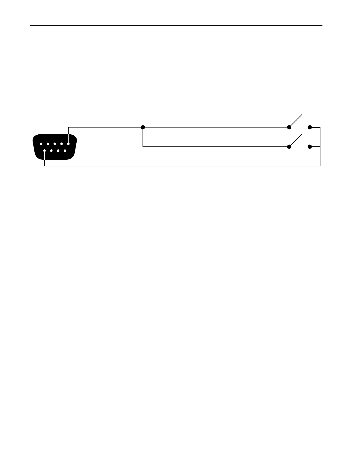
Multiple contact-closures or ‘open-collector’ logic outputs may be wired in parallel to a single Logic Input (see diagram below). Logic
Outputs and contact-closures should be rated for at least 5 Volts / 1mA operation. Low-current / dry-contact closures are recommended
for reliability. Active output driver circuits should not exceed a signal range of 0~5 Volts DC, and should have a minimum pulse width of
100 milli-seconds. Logic Input impedances are approximately 10k ohms.
multiple switches to single Logic Input
7
Page 9

RS-232 CONTROL
The DDL12 has an RS-232 Serial Port, which allows it to be controlled by a computer (see Front & Rear Panel Features on pg. 2). In
addition to the PC Control Software, the DDL12 offers two other methods of computer control.
Control Button Emulation:
This method allows the computer to imitate the operation of an infrared transmitter or wall-mount control
panel. Although the DDL12 does not accept infrared or wall-mount remote controls itself, it can still receive ASCII characters (via RS-232)
which emulate the buttons on these types of remote controls. From the factory, remote control buttons have equivalent ASCII characters
permanently assigned to them (see table below). Therefore, recall preset actions can be assigned to remote control buttons in the same
way they are assigned to Logic Inputs. Then, using this method, the computer can output ASCII characters which are equivalent to the
commands generated by those standard remote control buttons. Control Button Emulation allows the computer to utilize up to for ty button
definitions (unlike standard remote controls, which have only twenty-eight buttons). When using up to
four devices in a system, Control
Button Emulation also allows the computer to designate which device or devices should react to each control button command.
Advanced Computer Control:
This method provides advanced commands, which allow the computer to retrieve or edit level & delay
settings, as well as other functions. The computer may also emulate control buttons. Using this method, the computer may designate up
to sixty-four devices, and may create unlimited presets. The computer may also provide ‘real-time’ display of level & delay settings.
This manual only describes the Control Button Emulation method of computer control. For complete details about using the DDL12 with a
computer, including Advanced Computer Control, contact Biamp Systems for the manual "Computer Control
of ADVANTAGE® DDL12".
Each control button on an infrared transmitter or wall-mount control panel corresponds to one character in the standard ASCII character
set. The character equivalents are summarized in the following table. This table includes all forty possible buttons, their button numbers,
their ASCII code equivalents, and their factory default button definitions (no operation assigned).
button 01 B no operation assigned button 15 P no operation assigned button 29 ^ no operati on as signed
button 02 C no operation assigned button 16 Q no operation assigned butt on 30 _ no operation assigned
button 03 D no operation assigned button 17 R no operati on assigned button 31 ' no operation assigned
button 04 E no operati on as signed button 18 S no operation assigned button 32 b no operati on assigned
button 05 F no operation assigned but ton 19 T no operation assigned button 33 c no operation assigned
button 06 G no operation ass i gned button 20 U no operation assigned button 34 d no operation assigned
button 07 H no operation assigned button 21 V no operation assigned button 35 e no operat i on assigned
button 08 I no operati on assigned button 22 W no operation assigned button 36 f no operation assigned
button 09 J no operation assigned button 23 X no operation assigned button 37 g no operation assigned
button 10 K no operati on as signed button 24 Y no operation assigned button 38 h no operati on assigned
button 11 L no operation assigned button 25 Z no operation assigned button 39 i no operation assigned
button 12 M no operation assigned button 26 [ no operation assigned button 40 j no operation ass i gned
button 13 N no operation assigned button 27 \ no operation assigned
button 14 O no operation ass i gned button 28 ] no operati on assigned
When a control button is first pressed, the DDL12 receives the character which corresponds to that button. If the control button is pressed
longer than 110 milliseconds, the DDL12 receives a "repeat code", indicating the control button is still being pressed. The DDL12
continues to receive the repeat code (approximately nine times per second) until the control button is released. The ASCII character which
corresponds to the repeat code is @ (the "commercial at" sign). However, the DDL12 recall preset actions do not utilize repeat codes.
The computer can initiate any functions or actions that a standard control can, by simply transmitting the equivalent control button ASCII
character. When interfacing the DDL12 to a computer, the computer must be aware that the DDL12 will ‘echo’ all characters it receives
(both from computer and Logic Inputs) via the Serial Port Transmit Data (TXD) output signal. However, from the factory, the DDL12 Logic
inputs are programmed with no ‘echo character’ assigned to them.
When using Control Button Emulation, up to
four ADVANTAGE® products may be connected together and addressed individually. When
multiple units are used, each unit is assigned a unique "Device #" (see Front & Rear Panel Features on pg. 2). Normally, all units would
react to control button commands. However, a computer can send commands to specific units, by preceding each command with a
"device select prefix" character (see table below). Only those units whose Device #s are specified will respond to the command which
follows. If a command is not preceded by a device select prefix character, then all units in the system will react to that command.
Select Device 1 l Select Devices 2 & 3 q Select Devices 1 & 2 & 4 v
Select Device 2 m Select Devices 1 & 2 & 3 r Select Devices 3 & 4 w
Select Devices 1 & 2 n Select Device 4 s Select Devices 1 & 3 & 4 x
Select Device 3 o Select Devices 1 & 4 t Select Devices 2 & 3 & 4 y
Select Devices 1 & 3 p Select Devices 2 & 4 u Select Devices 1 & 2 & 3 & 4 z
8
Page 10
RS-232 CONTROL
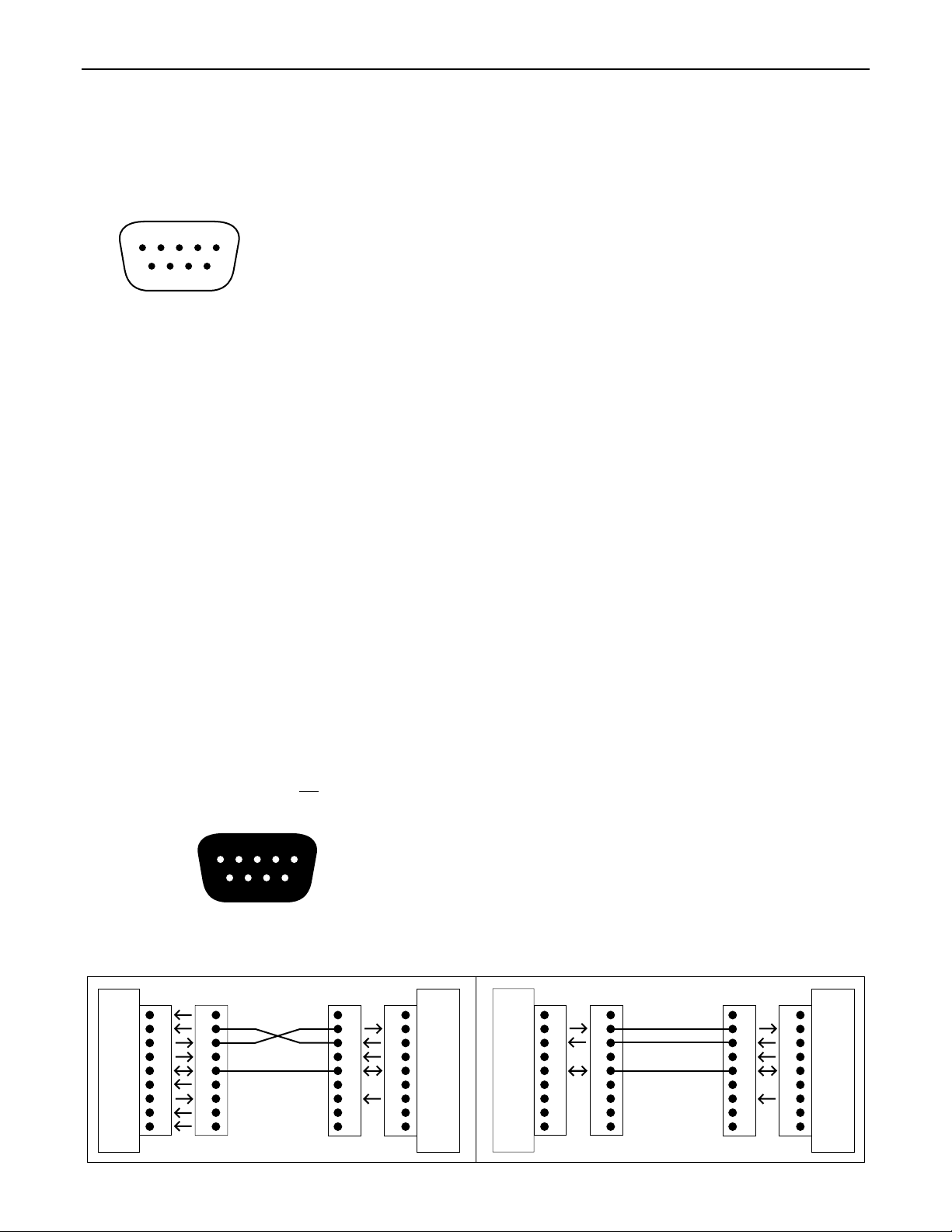
Serial Port:
The 9-pin Sub-D (male) connector on the DDL12 rear panel provides the RS-232 compatible serial interface signals used for
computer control. The DDL12 Serial Port transmits serial data on pin 3 (TxD), receives serial data on pin 2 (RxD), and provides a ground
on Pin 5. The Data Terminal Ready (DTR) & Request To Send (RTS) output signals are connected to the +12 Volt power supply (through
a resistor) and are always asserted when the DDL12 power is on.
NOTE: The Serial Port may also transmit commands which are
received via the Logic Inputs, depending upon the echo character assignments (see Setup on pg. 4).
54321
pin #1 = not used
pin #2 = Receive Data (RxD) input
pin #3 = Transmit Data (TxD) output
9876
pin #4 = Data Terminal Ready (DTR) output
pin #6 = not used
pin #7 = Request To Send (RTS) output
pin #8 = not used
pin #9 = not used
pin #5 = ground
serial port
The DDL12 only requires receive data (pin 2), transmit data (pin 3), and signal ground (pin 5) to be connected for successful data
communications (see cable diagram below). However, the PC may require that signals be present on the data set ready, clear to send, or
carrier detect inputs, as well as the receive data, transmit data, and signal ground pins. Success or failure depends entirely on the actual
computer hardware and software being used. When trying to solve an interfacing problem, the most important thing to remember is that an
output of one device should connect to one or more inputs of the other device, and that two outputs should never be connected together.
Also, keep in mind that the RS-232 specification calls for the cable length to be no greater than 50 feet (although it is not unusual to be
able to operate over distances of 150 to 250 feet), and the connectors must be of the appropriate gender (male or female) to mate
properly. For best results, a shielded cable should be used, with the shield connected to signal ground. Since the DDL12 serial interface
ground is also tied (indirectly) to the analog signal ground, undesirable ground loops may occur when the DDL12 is connected to a PC (if
the system grounding is not carefully designed). For best performance, the PC ground and the chassis ground of the DDL12 should be at
the same potential, and the PC should get AC power from the same source as the DDL12 (and any other audio equipment which is
connected to the DDL12)
.
Serial Port Dat a Commu nicatio ns Parame ters:
The DDL12 communicates through the Serial Port at the factory selected rate of 9600
bits per second, with 8 data bits, 1 stop bit, and no parity. The DDL12 utilizes a subset of the standard 7-bit ASCII character set. The
eighth data bit of each character (the most significant bit) should always be 0. The computer should not echo the characters it receives.
The computer should not be set for either hardware (DTR) or software (XON/XOFF) flow control. The baud rate may be changed to either
2400 or 19,200 bits per second by means of the rear panel Baud Rate DIP switches.
Link Port Connections:
signals used for linking multiple ADVANTAGE
the next device, and so forth (see diagram below). Link cables are available as an option (Biamp #909-0057-00).
The 9-pin Sub-D (female) connector on the DDL12 rear panel provides the RS-232 compatible serial interface
®
products within a system. The Link Port of one device simply connects to the Serial Port of
NOTE: All but the final
device in a system should have its ‘last’ switch down (see Front & Rear Panel Features on pg. 2). The Link Port will also transmit
commands which are received via the Logic Inputs.
12345
pin #1 = not used
pin #2 = Transmit Data (TxD) output
pin #3 = Receive Data (RxD) input
6789
pin #4 = not used
pin #6 = not used
pin #7 = not used
pin #8 = not used
pin #9 = not used
pin #5 = ground
link port
PC
CD
RxD
TxD
DTR
gnd
DSR
RTS
CTS
RI
male female
serial port
1
2
3
4
5
6
7
8
9
Serial Cable
1
2
3
4
5
6
7
8
9
(shield)
serial port
1
1
2
2
3
3
4
4
5
5
6
6
7
7
8
8
9
9
female male
DDL12
n/a
RxD
TxD
DTR
gnd
n/a
RTS
n/a
n/a
DDL12
n/a
TxD
RxD
n/a
gnd
n/a
n/a
n/a
n/a
link port
1
2
3
4
5
6
7
8
9
female male
1
2
3
4
5
6
7
8
9
Link Cable
(shield)
serial port
1
1
2
2
3
3
4
4
5
5
6
6
7
7
8
8
9
9
female male
unit 2
n/a
RxD
TxD
DTR
gnd
n/a
RTS
n/a
n/a
9
Page 11

main
speaker
system
CHURCH
10
altar
60 feet (18.3m)
pews
balcony
under-balcony
delayed speakers
5 feet
(1.5m)
listener listener
20 feet (6.1m)
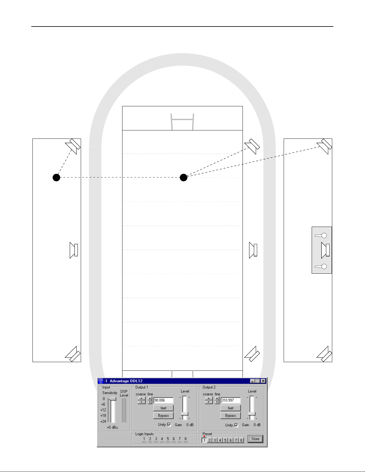
APPLICATIONS
narthex
delayed
speakers
5 feet
(1.5m)
narthex
Page 12
APPLICATIONS
SPORTS FIELD
delayed
bleacher
speakers
45 feet
(13.7m)
170 feet (51.8m)
listener listener
96 feet (29.3m)
186 feet (56.7m)
delayed
field
speakers
main
speaker
system
press
box
visitor
bleachers
home
bleachers
11
Page 13
SPECIFICATIONS & BLOCK DIAGRAM
Frequency Response
THD + Noise
Dynamic Range
Input Impedance
Maximum Input
Output Impedance:
Maximum Output
Delay Range:
Delay Resolution
Sampling Rate:
(20Hz~20kHz @ +4dBu)
(20Hz~20kHz @ +4dBu)
(20Hz~20kHz)
(balanced)
(unity gain)
(2k ohm load)
(minimum increments)
:
:
:
:
:
:
1.25 mSec to 1.35 Sec width 19 inches (483mm)
:
+0/-0.5dB
< 0.01%
88dB
20k ohms
+24dBu
200 ohms
+24dBu height (1 rack -space) 1.75 inches (44mm)
20.8 uS depth 7 inches (178mm)
48kHz
Analog-to-Digital Converter:
Digital-to-Analog Converter:
Propagation Delay:
Power Requirements:
Power Consumption:
Dimensions:
Weight:
64x oversampled 16- bit sigma-delta
128x oversampled 16- bit sigma-delta
1.25mSec
115/230VAC 50/60Hz
< 10 watts
5.8 lbs (2.63kg)
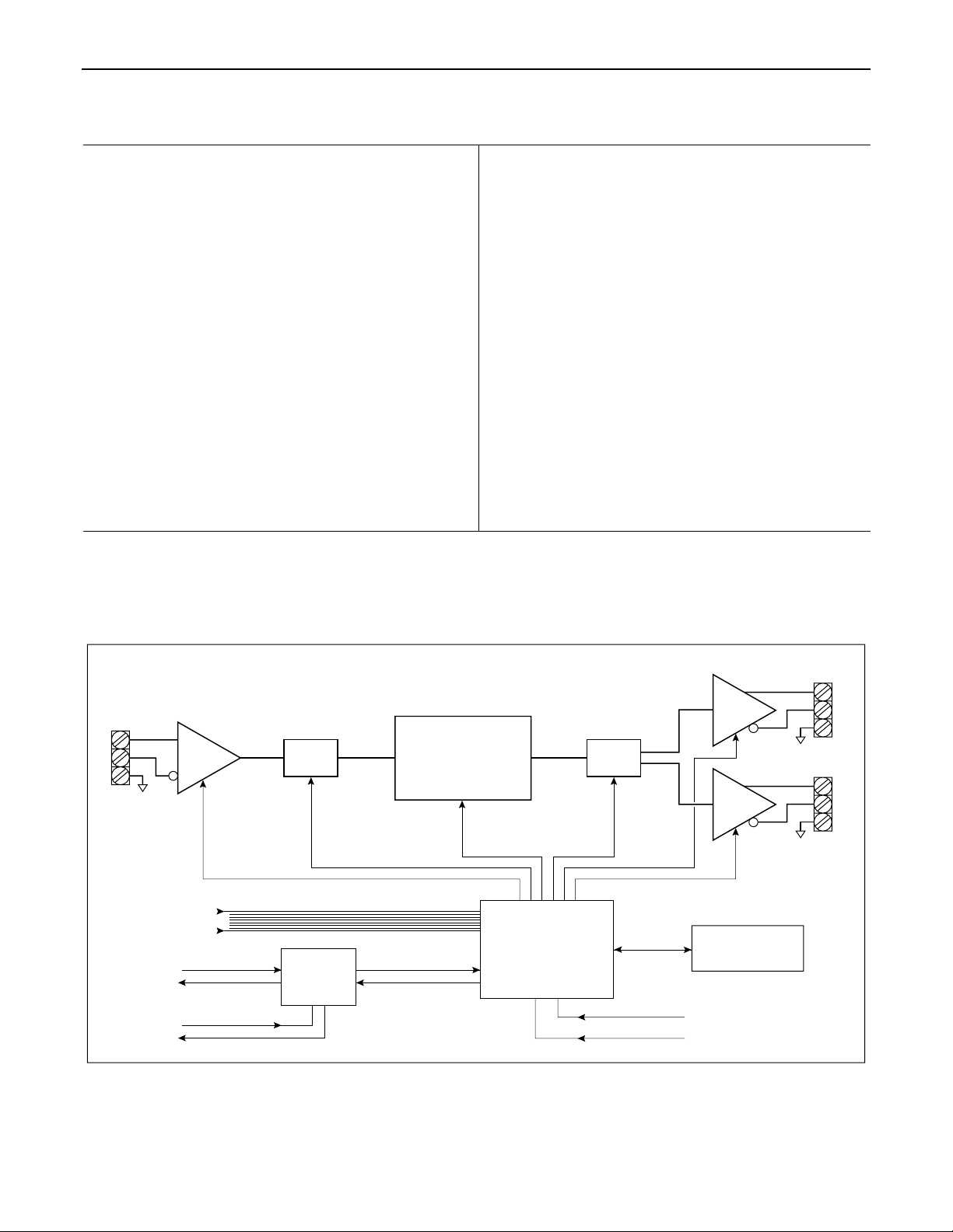
Input
logic inputs
receive
send
link port
gain
A/D
RS-232
serial
port
DDL12 Block Diagram
Digital Signal
Processor
&
DRAM
microprocessor
D/A
Output 1
gain
Output 2
gain
non-volatile
memory
baud rate DIP switch
device # DIP switch
12
Page 14

WARRANTY
BIAMP SYSTEMS IS PLEASED TO EXTEND THE FOLLOWING 5-YEAR
LIMITED WARRANTY TO THE ORIGINAL PURCHASER OF THE
PROFESSIONAL SOUND EQUIPMENT DESCRIBED IN THIS MANUAL.
BIAMP Systems expressly warrants this product to be
free from defects in material and workmanship for a
period of 5 YEARS from the date of purchase as a
new product from an authorized BIAMP Systems
dealer under the following conditions.
1. The Purchaser is responsible for completing and
mailing to BIAMP Systems, within 10 days of
purchase, the attached warranty application.
2. In the event the warranted BIAMP Systems product
requires service during the warranty period, BIAMP
Systems will repair or replace, at its option, defective
materials, provided you have identified yourself as the
original purchaser of the product to any authorized
BIAMP Systems Service Center. Transportation and
insurance charges to and from an authorized Service
Center or the BIAMP Systems factory for warranted
products or components thereof to obtain repairs shall
be the responsibility of the purchaser.
3. This warranty will be VOIDED if the serial number
has been removed or defaced; or if the product has
been subjected to accidental damage, abuse, rental
usage, alterations, or attempted repair by any person
not authorized by BIAMP Systems to make repairs; or
if the product has been installed contrary to BIAMP
Systems's recommendations.
4. Electro-mechanical fans, electrolytic capacitors,
and the normal wear and tear of appearance items
such as paint, knobs, handles, and covers are not
covered under this warranty.
5. BIAMP SYSTEMS SHALL NOT IN ANY EVENT BE
LIABLE FOR SPECIAL, INCIDENTAL, OR
CONSEQUENTIAL DAMAGES, INCLUDING LOST
PROFITS, LOSS OF USE, PRO PERTY DAM AGE, IN JURY
TO GOODWILL, OR OTHER ECONOMIC LOSS OF ANY
SORT. EXCEPT AS EXPRESSLY PROVIDED HEREIN,
BIAMP SYSTEMS DISCLAIMS AL L OTHER LIABILIT Y TO
PURCHASER OR ANY OTHER PERSONS ARISING OUT
OF USE OR PERFORMANCE OF THE PRODUCT,
INCLUDING LIABILITY FOR NEGLIGENCE OR STRICT
LIABILITY IN TORT.
6. THIS WARRANTY IS IN LIEU OF ALL OTHER
WARRANTIES EXPRESSED OR IMPLIED. BIAMP
SYSTEMS EXPRESSLY DISCLAIMS ALL IMPLIED
WARRANTIES OF MERCHANTABILITY AND FITNESS
FOR A PARTICULAR PURPOSE. THE REMEDIES SET
FORTH HEREIN SHALL BE THE PURCHASER'S SOLE
AND EXCLUSIVE REMEDIES WITH RESPECT TO ANY
DEFECTIVE PRODUCT. THE AGENTS, EMPLOYEES,
DISTRIBUTORS, AND DEALERS OF BIAMP SYSTEMS
ARE NOT AUTHORIZED TO MODIFY THIS WARRANTY
OR TO MAKE ADDITIONAL WARRANTIES BINDING O N
BIAMP SYSTEMS. ACCORDINGLY, ADDITIONAL
STATEMENTS SUCH AS DEALER ADVERTISEMENTS
OR REPRESENTATIONS DO NOT CONSTITUTE
WARRANTIES BY BIAMP SYSTEMS.
7. No action for breach of this warranty may be
commenced more than one year after the expiration of this
warranty.
Thank you for purchasing BIAMP SYSTEMS...
AMERICAN SOUND CRAFTSMANSHIP
Biamp Systems
10074 S.W. Arctic Drive
Beaverton, Oregon 97005
(503) 641-7287
http://www.biamp.com
585.0144.00
 Loading...