

Page 1

Desono™
CM Ceiling Loudspeaker
Installation & Operation Guide
MODELS
CM20DTS
CM30DTD
CM60DTD
PRODUCT DESCRIPTION FEATURES
The Desono CM ceiling loudspeakers deliver crystal
clear audio for all your public address and background
music needs. The sealed back can and bass reflex
port give a controlled sound performance in any ceiling
structure. The ultra-slim housing with minimal built-in
depth has been tuned to optimize bass and midrange
performance while maintaining sonic consistency. The
matching sound image allows combining various models
in the same room or area.
All models have a tool-free rotatable 16 ohm and
70/100 volt power selector on the front. Designed with
the installer in mind, they can be blind-mounted from
below the ceiling, and feature a magnetic grille for easy
toolless installation and removal and can also be painted
to match the room decor. Additionally, the tap switch is
located on the face of the loudspeaker, so adjustments
can be made without requiring ceiling access.
Desono CM ceiling loudspeakers are an ideal choice
for a multitude of environments that demand superior
speech intelligibility and full range music reproduction.
• Ceiling loudspeaker with back can for controlled sound
performance in any ceiling structure
• Tuned bass reflex port for optimised low-frequency
performance
• 4.25” LF driver for CM20DTS and CM30DTD, both with 1”
tweeter
• 6.5” LF driver for CM60DTD, with 1” tweeter
• 60 W dynamic power handling for CM20DTS, 80 W for
CM30DTD and 120 W for CM60DTD
• Thin-edge loudspeaker grille for elegant integration
• Easy grille mounting with integrated neodymium magnets
• Grille safety wire prevents grille from falling during and after
installation
• Paintable in any RAL color
• Included tile bridge support rails prevent ceiling tile sagging
• Quick installation with two fast screwing loudspeaker clamps
• Minimal built-in depth with uncompromised acoustical
performance
• Loudspeaker overload protection for a 24/7 failsafe operation
• Front panel selection of 16 ohm or 100V/70V operation allows
for easy power adjustment without removing the loudspeaker
from the ceiling or moving connection wires
• Enhanced cable management with incorporated strain relief
and cable guidance along with provision for a cable gland
• In & Link connection with permanent pass through on the
euroblock connector allows easy daisy chaining of multiple
loudspeakers
• Two seismic safety tabs for connecting safety cables
A: 9300 S.W. Gemini Drive Beaverton, OR 97008 USA W: www.biamp.com
Page 2
SUPPLIED ITEMS
Unpack the contents and confirm following items are
included:
• Loudspeaker x 2
• Thin-edge grille x 2
• Tile rail x 4
• Tile rail spacer x 4
• Cutout template x 2
• Important safety instructions x 1
Loudspeaker wires and safety cables are not included.
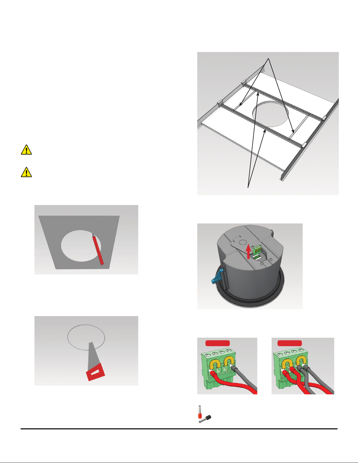
INSTALLATION INSTRUCTIONS
CAUTION: Biamp is not responsible for damages resulting
from the negligent installation of any loudspeaker.
WARNING: Make sure that the mounting structure is
capable of safely supporting the loudspeaker’s weight.
3. Insert the two tile rails through the cut hole and place
them on the ceiling surface near the opening. Insert
the tile rail spacers in the hole and clip them on the
tile rails.
Tile rail spacers
1. Use the cutout template to mark the mounting hole.
2. Cut the mounting hole. Make sure there are no cables
or other obstructions behind the mounting panel to
avoid damaging power cables or other infrastructure.
Tile rails
4. Open the connection box on the back of the
loudspeaker and remove the euroblock connector.
5. Pull the loudspeaker wires through the mounting hole
and connect them to the euroblock terminal.
+ + - -
+ + - -
wiring: single cable
Use wire ferrules when stranded
wire is used.
wiring: daisy-chained to next unit
page 2 Installation and Operation Guide CM Loudspeaker
Page 3

6. Remove the grille from the loudspeaker. The grille
is connected to the loudspeaker frame with a
detachable wire for installer convenience and to
serve as a grille safety restraint.
7. Turn the mounting clamps inwards (a) and tighten the
screws slightly to secure them in the inward position
(b).
10. Attach a safety cable to one or both provided seismic
safety tabs to secure the back can to the building
structure.
WARNING:
Follow applicable
building regulations when
installing this loudspeaker.
Otherwise the unit could
fall, resulting in personal
injury or death.
WARNING: Install the safety cable with as little slack as
possible. If the safety cable is too long it may snap from
excessive strain if the loudspeaker falls.
11. Set the power selector on the front of the loudspeaker
to the required position. The selector switch allows for
power adjustment without requiring ceiling access.
2x
a
b
8. Insert the euroblock connector in the connection box
on the back of the loudspeaker and close the cover.
This cover acts as a strain relief plate for the cable
and retainer for the euroblock connector. Use the
knockout (a) of 22mm (0.87 inch) on the cover if the
installation requires the use of a cable gland (b).
a
b
WARNING: Only use a non-conductive cable gland.
9. Insert the loudspeaker into the hole and rotate the
mounting clamp screws outwards to secure the
speaker in place. Align the clamps with the tile rails
and do not overtighten the mounting clamp screws.
WARNING: Set the power selector prior to applying audio
and only change the setting while the audio amplifer is shut
off.
CAUTION: The 16 ohm setting is not compatible with 70
volt or 100 volt line amplifiers.
CAUTION: The highest 70 volt power setting is not
compatible with 100 volt line amplifiers, only with 70 volt
line amplifiers.
12. Install the grille on the loudspeaker. The grille is held
in place by magnets.
The grille may be painted to match decor.
See the painting instructions on page 6.
CM Loudspeaker Installation and Operation Guide page 3
Page 4

Dimensions - CM20DTS
A
C
B (cutout)
Dimensions - CM30DTD
mm inch
A 223 8.780
B 193 7.59 8
mm inch
C 5 0.1 97
D 84 3.307
D
A
mm inch
A 223 8.780
B 193 7.59 8
C
mm inch
C 5 0.1 97
D 131 5.157
B (cutout)
Dimensions - CM60DTD
B (cutout)
A
mm inch
A 258 10 .157
B 232 9 .13 4
D
C
mm inch
C 5 0.1 97
D 157 6.181
D
page 4 Installation and Operation Guide CM Loudspeaker
Page 5
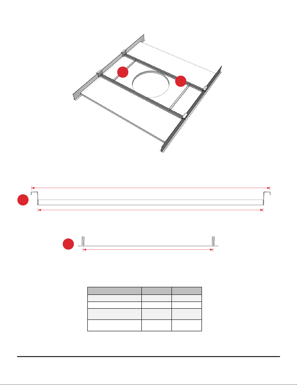
Dimensions - tile rail and tile spacer
2
1
A
1
B
2
C
mm inch
A 627 ± 5 24.685 ± 0,197
B 594 23.385
(CM20DTS / CM30DTD)
C
C
(CM 60DTD)
190 7.4 8 0
228 8.976
CM Loudspeaker Installation and Operation Guide page 5
Page 6

PAINTING INSTRUCTIONS
The grille may be painted to match room decor. Remove the
scrim material (cloth) prior to painting.
1. Purchase a citrus-based label/adhesive remover
spray (PRF Label O®, Goo Gone® or similar).
2. Pull the grille away from the cabinet. Do not bend the
grille.
3. Gently pry the logo from the grille using a nonmetallic tool, or fully mask the logo. Use a sharp knife
to trim the masking material close to the edges of the
masked areas.
4. Remove the grille cloth (scrim material) by spraying
all of the fabric with the adhesive remover.
5. Wait a few minutes to allow the fabric to fully absorb
the spray.
6. Carefully peel o the grille cloth, taking care not to rip
or stretch the fabric.
7. Once the cloth and logo have been removed, some
glue residue may remain on the grille. If so, apply
additional adhesive remover to remove the glue.
8. Thoroughly clean and degrease the grille before
painting. Do not use a solvent (see Cautions above).
9. Paint the grille with several light coats of spray paint.
Do not clog the grille perforations with paint.
10. Allow the paint to fully dry and cure.
11. Reattach the grille cloth. Use a light coat of
simple contact adhesive. Avoid clogging the grille
perforations with any adhesive.
12. Press and smooth the cloth on the grille.
13. Reattach the logo if required.
14. Attach the grille to the back can per the installation
instructions.
CAUTION: NEVER use abrasives, gasoline,
kerosene, acetone, methyl ethyl ketone (MEK),
paint thinner, harsh detergents or other chemicals on
the loudspeaker. These chemicals and agents may
permanently damage the nish. Some are also toxic
and highly ammable.
IMPORTANT: Do not bend or damage the grille on
removal or reinstallation.
IMPORTANT: Blocking the grille holes with paint or
getting any paint on the drivers or internal parts will
aect loudspeaker performance and void the warranty.
CONTACT US
Email: support@biamp.com
Web: support.biamp.com
Warranty: biamp.com/legal/warranty-information
Safety & Compliance: biamp.com/compliance
A: 9300 S.W. Gemini Drive Beaverton, OR 97008 USA W: www.biamp.com
JULY 2021
 Loading...