

Biamp Cambridge Qt 300, CambridgeQt 600 Installation And Operation Manual

Qt® 300/600
Installation and Operations Guide

345
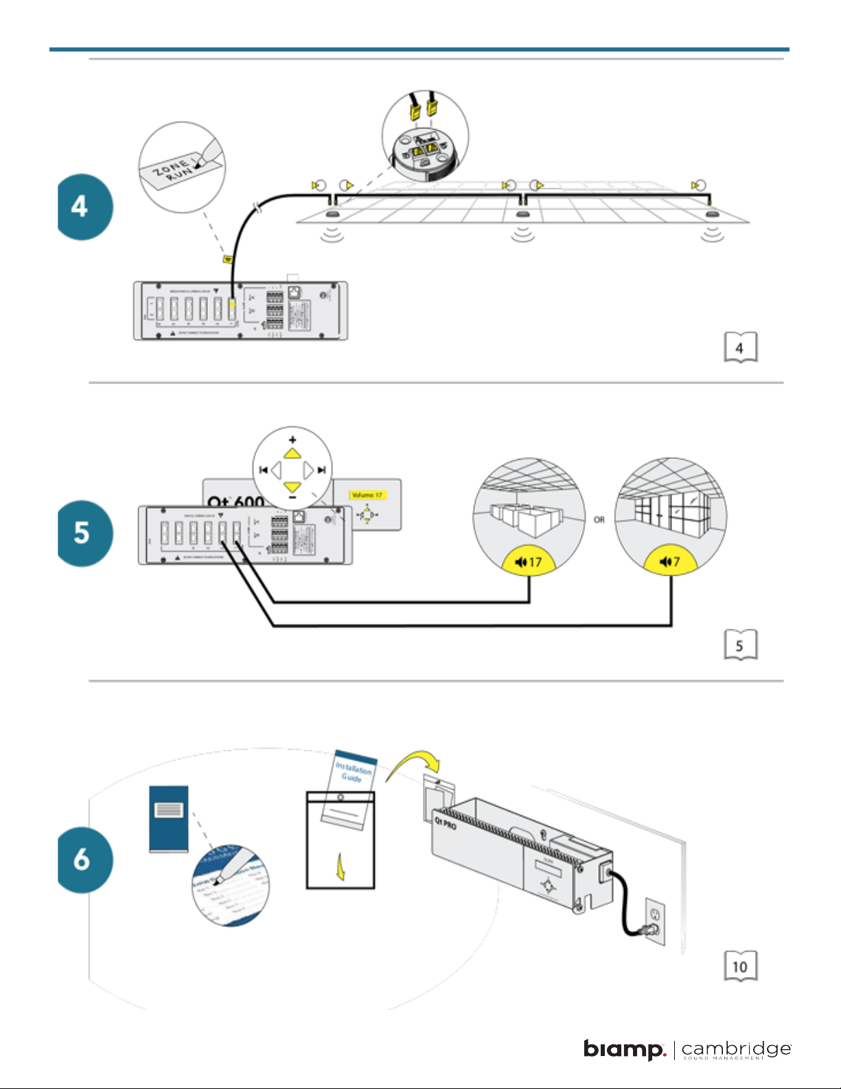

Table of Contents
Safety Information . . . . . . . . . . . . . . . . . . . . . . . . . . . . . . . . . 7
Qt 300/600 Introduction. . . . . . . . . . . . . . . . . . . . . . . . . . . . . . .8
Sound Masking Emitter Types . . . . . . . . . . . . . . . . . . . . . . . . . . . . . . . . . . . . . . . . 8
Hardware Installation . . . . . . . . . . . . . . . . . . . . . . . . . . . . . . . 10
Installing the Control Module. . . . . . . . . . . . . . . . . . . . . . . . . . . . . . . . . . . . . . . . 10
Wall Mount . . . . . . . . . . . . . . . . . . . . . . . . . . . . . . . . . . . . . . . . . . . . . . . . . 10
Rack Mount . . . . . . . . . . . . . . . . . . . . . . . . . . . . . . . . . . . . . . . . . . . . . . . . 10
Installing the Qt Emitters . . . . . . . . . . . . . . . . . . . . . . . . . . . . . . . . . . . . . . . . . . .11
Standard Emitter Installation . . . . . . . . . . . . . . . . . . . . . . . . . . . . . . . . . . . . . . . . .11
Active Emitter Installation . . . . . . . . . . . . . . . . . . . . . . . . . . . . . . . . . . . . . . . . . 12
Table 1 . . . . . . . . . . . . . . . . . . . . . . . . . . . . . . . . . . . . . . . . . . . . . . . . . . . 13
Installing Paging or Music to the Audio Inputs . . . . . . . . . . . . . . . . . . . . . . . . . . . . . . . 13
Installing Contact Closures. . . . . . . . . . . . . . . . . . . . . . . . . . . . . . . . . . . . . . . . . 13
Custom Cabling Guidelines . . . . . . . . . . . . . . . . . . . . . . . . . . . 14
Important Considerations . . . . . . . . . . . . . . . . . . . . . . . . . . . . . . . . . . . . . . . . . 14
Battery Replacement . . . . . . . . . . . . . . . . . . . . . . . . . . . . . . . 14
System Conguration . . . . . . . . . . . . . . . . . . . . . . . . . . . . . . 15
System Congurable Feature List (Front Panel / MCS) . . . . . . . . . . . . . . . . . . . . . . . . . . 15
Conguring the Control Module for the Network . . . . . . . . . . . . . . . . . . . . . . . . . . . . . . 16
Front Panel Control . . . . . . . . . . . . . . . . . . . . . . . . . . . . . . . . . . . . . . . . . . . . 16
System Information. . . . . . . . . . . . . . . . . . . . . . . . . . . . . . . . . . . . . . . . . . . . . 16
Setting Sound Masking Levels . . . . . . . . . . . . . . . . . . . . . . . . . . . . . . . . . . . . . . . 17
Setting Audio Input Levels . . . . . . . . . . . . . . . . . . . . . . . . . . . . . . . . . . . . . . . . . 18
Lock/Unlock the Front Panel . . . . . . . . . . . . . . . . . . . . . . . . . . . . . . . . . . . . . . . . 19
Congure Network Name and IP Address . . . . . . . . . . . . . . . . . . . . . . . . . . . . . . . . . 19
Real-Time Clock or Network Clock. . . . . . . . . . . . . . . . . . . . . . . . . . . . . . . . . . . . . 19
Reset System to Default Settings . . . . . . . . . . . . . . . . . . . . . . . . . . . . . . . . . . . . . 20
System Control Using Monitor Control Software (MCS) . . . . . . . . . . . . . . . . . . . . . . . . . . 20
DHCP Support . . . . . . . . . . . . . . . . . . . . . . . . . . . . . . . . . . . . . . . . . . . . . . . 21
MCS: Operation Screen . . . . . . . . . . . . . . . . . . . . . . . . . . . . . 21
Setting Emitter Type and Masking Spectrum per Zone . . . . . . . . . . . . . . . . . . . . . . . . . . 22
Changing Masking Level Using MCS . . . . . . . . . . . . . . . . . . . . . . . . . . . . . . . . . . . 23
Auto Ramping . . . . . . . . . . . . . . . . . . . . . . . . . . . . . . . . . . . . . . . . . . . . . . . 23
Changing Inputs A and B Min/Max Levels . . . . . . . . . . . . . . . . . . . . . . . . . . . . . . . . . 24
Auxiliary Line Level Adjustment . . . . . . . . . . . . . . . . . . . . . . . . . . . . . . . . . . . . . . 24
Time of Day Masking and Audio . . . . . . . . . . . . . . . . . . . . . . . . . . . . . . . . . . . . . . 25
Errors. . . . . . . . . . . . . . . . . . . . . . . . . . . . . . . . . . . . . . . . . . . . . . . . . . . . 26

MCS: Administration Section . . . . . . . . . . . . . . . . . . . . . . . . . . 27
Service . . . . . . . . . . . . . . . . . . . . . . . . . . . . . . . . . . . . . . . . . . . . . . . . . . . 27
Zone Names . . . . . . . . . . . . . . . . . . . . . . . . . . . . . . . . . . . . . . . . . . . . . . . . 27
Networking and Security . . . . . . . . . . . . . . . . . . . . . . . . . . . . . . . . . . . . . . . . . . 28
Notication of Errors . . . . . . . . . . . . . . . . . . . . . . . . . . . . . . . . . . . . . . . . . . . . 28
Date and Time – Time Zone . . . . . . . . . . . . . . . . . . . . . . . . . . . . . . . . . . . . . . . . 28
Setting Equalizers and Emitter Fault Detection . . . . . . . . . . . . . . . . . . . . . . . . . . . . . . 29
Equalizer Update. . . . . . . . . . . . . . . . . . . . . . . . . . . . . . . . . . . . . . . . . . . . . . 29
Emitter Network Fault Detection . . . . . . . . . . . . . . . . . . . . . . . . . . . . . . . . . . . . . . 30
MCS: Help . . . . . . . . . . . . . . . . . . . . . . . . . . . . . . . . . . . . . . . . . . . . . . . . . 31
Links to Help Topics . . . . . . . . . . . . . . . . . . . . . . . . . . . . . . . . . . . . . . . . . . . . 32
Operations and Administration . . . . . . . . . . . . . . . . . . . . . . . . . . . . . . . . . . . . . . . 32
Software Update . . . . . . . . . . . . . . . . . . . . . . . . . . . . . . . . . . . . . . . . . . . . . . 32
MCS: Printout . . . . . . . . . . . . . . . . . . . . . . . . . . . . . . . . . . . . . . . . . . . . . . . 32
Error Codes and Clear Error . . . . . . . . . . . . . . . . . . . . . . . . . . . 33
Post-Installation Hando . . . . . . . . . . . . . . . . . . . . . . . . . . . . . 34
Warranty. . . . . . . . . . . . . . . . . . . . . . . . . . . . . . . . . . . . . . 35
6

Safety Information
1. Read these instructions.
2. Keep these instructions.
3. Heed all warnings.
4. Follow all instructions.
5. Do not use this apparatus near water. Indoor use only.
6. Clean only with dry cloth.
7. Do not block any ventilation openings. Install in accordance with the manufacturer’s instructions.
8. Do not install near any heat sources such as radiators, heat registers, stoves, or other apparatus (including
ampliers) that produce heat.
9. Use only power supply provided with the unit.
10. Do not defeat the safety purpose of the polarized or grounding-type plug. A polarized plug has two blades
with one wider than the other. A grounding type plug has two blades and a third grounding prong. The wide
blade or the third prong is provided for your safety. If the provided plug does not t into your outlet, consult
an electrician for replacement of the obsolete outlet.
11. Protect the power cord from being walked on or pinched particularly at plugs, convenience receptacles, and
the point where they exit from the apparatus.
12. Only use attachments/accessories specied by the manufacturer.
13. Unplug this apparatus during lightning storms or when unused for long periods of time.
14. Refer all servicing to qualied service personnel. Servicing is required when the apparatus has been
damaged in any way, such as power-supply cord or plug is damaged, liquid has been spilled or objects
have fallen into the apparatus, the apparatus has been exposed to rain or moisture, does not operate
normally, or has been dropped.
15. This product contains a lithium battery that is not user replaceable. The battery may be replaced by
qualied service personnel only.
DANGER OF EXPLOSION IF BATTERY IS INCORRECTLY REPLACED.
REPLACE ONLY WITH THE SAME OR EQUIVALENT TYPE.
!
7

Qt 300/600 Introduction
This manual discusses the installation of a sound masking system using either the Qt 300 or the Qt 600. The
Qt 300 and Qt 600 controllers have identical functionality, but dierent number of zones supported - the Qt
300 supports 3 zones whereas the Qt 600 supports 6 zones. As you use this guide, remember the number of
zones and total area of coverage is the only real functional dierence between the systems. Collectively, the
systems are referred to as ‘QtPro’ throughout this guide.
The Qt 600 supports six zones of sound masking, each with 1 to 120 Standard Emitters covering 100 to 12,000
square feet (9.3²) - 1,115²) per zone. The Qt 300 supports three zones of sound masking, each with 1 to 120
Standard Emitters, covering up to 12,000 square feet per zone (1,115²).
Sound Masking Emitter Types
There are two dierent sound masking emitter choices for consideration, both are direct eld devices meaning
that they are mounted downward for direct unimpeded transfer of an audio signal to the listening location.
Qt Standard Emitter – Is a passive audio loudspeaker device suitable for sound masking and limited output
level paging applications. This emitter receives an amplied signal directly from the QtPro control processor via
a UTP category cabling infrastructure. Maximum sound pressure levels with this type of emitter are 55 dBA at 1
meter with a sound masking frequency response of 200Hz to 6.3kHz.
Qt Active Emitter – Is an active (self-powered) audio loudspeaker device suitable for sound masking as well
as paging/ background music environments. This emitter contains an internal amplier which receives the
audio signal directly from the QtPro control processor in addition to a direct current voltage which powers the
Qt Active Emitter device. Both power supply(s) and voltage injectors are required for operation in addition to
the QtPro control processor. Maximum sound pressure levels with this type of emitter are 74 dBA @ 1 meter
with a sound masking frequency response of 125Hz to 8 kHz.
Each system comes with two audio inputs which can be used for paging and/or music. Additional controls for
each zone include time-of-day masking, auto ramping, self-monitoring fault detection and notication, and
independent equalizers for masking and audio inputs. The system may be operated from its control module
front panel or by a computer directly connected to the module or by a computer connected through a local
area network. See system conguration on page 15.
It is important that the control module’s masking volumes be set correctly for each zone to obtain the full
eectiveness of the system. If volumes are set too low, speech privacy will be reduced and work place
distractions will be much more apparent. If volumes are set too high, the masking sound itself could become a
source of distraction. The higher the setting that can be used comfortably, the better the acoustic privacy. For a
given open oce design, including ceiling height, ceiling material and workstation panel height, we can dene
the masking volume required to achieve “normal acoustic privacy,” i.e., when it is relatively easy to ignore
surrounding conversations. For a very large range of open oce designs, the target level is in the 45–48 dBA
range, measured 3 ft (0.9 m) above oor level. Similarly, for private oces, based on wall panel design and
ceiling construction, we can dene masking volumes required to achieve “condential privacy,”
i.e., conversations in adjacent oces cannot be understood. Most private oces have a target level in the
38–42 dBA range, averaged spatially within the oce.
8

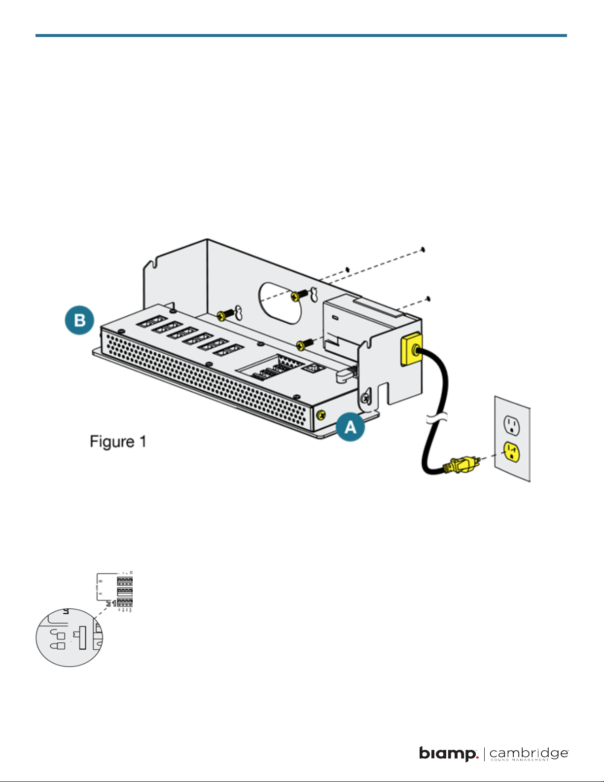
Setting the masking volumes can be approached in one of two ways:
BEST: If a sound level meter is available, it is recommended that the control module’s masking volumes be
adjusted up or down to achieve the following readings on the meter:
• Private Oce Zones: 38-42 dBA, averaged spatially within the oce
• Open Area Zones: 45-48 dBA, measured 3 ft (0.9 m) above oor level
OTHERWISE: If a sound level meter is not available, the above levels are likely to be achieved in most
environments by setting the control module’s masking volumes as follows:
• Private Oce Zones: 05-09, for all ceiling heights
• Open Area Zones:
• 11-14, for 8 ft (2.4 m) ceilings
• 13-16, for 10 ft (3 m) ceilings
• 15-18, for 12 ft (3.7 m) ceilings
Masking volumes must be set suciently high to improve speech privacy and reduce distraction but not so high
that the masking sound becomes objectionable. Settings within the above ranges should accommodate both
objectives. As a general rule, use the high end of the range. Base nal settings on site conditions and customer
preferences. If people object to the sound level, set masking volumes toward the bottom of the range or refer
to the ‘Ramping’ section of this guide, found on page 22 for more information on introducing masking into the
space gradually. Remember that the eectiveness of the system relies on sucient masking sound level and
that initial objections are often overcome as people become accustomed to the sound.
Dierent day and a night volumes may be set. The control module ramps linearly between these two settings
beginning at the time specied and over the period of time specied. As the control module ramps between
settings, the current volume is displayed under “Current.”
NOTE: This document uses the QtPro software version 6.6.0 or higher for feature conguration.
9
Hardware Installation
Installing the Control Module
NOTE: Always plug/unplug power supply at wall outlet.
NOTE: The Qt 600 is shown in the gures, but the Qt 300 installs in the same manner.
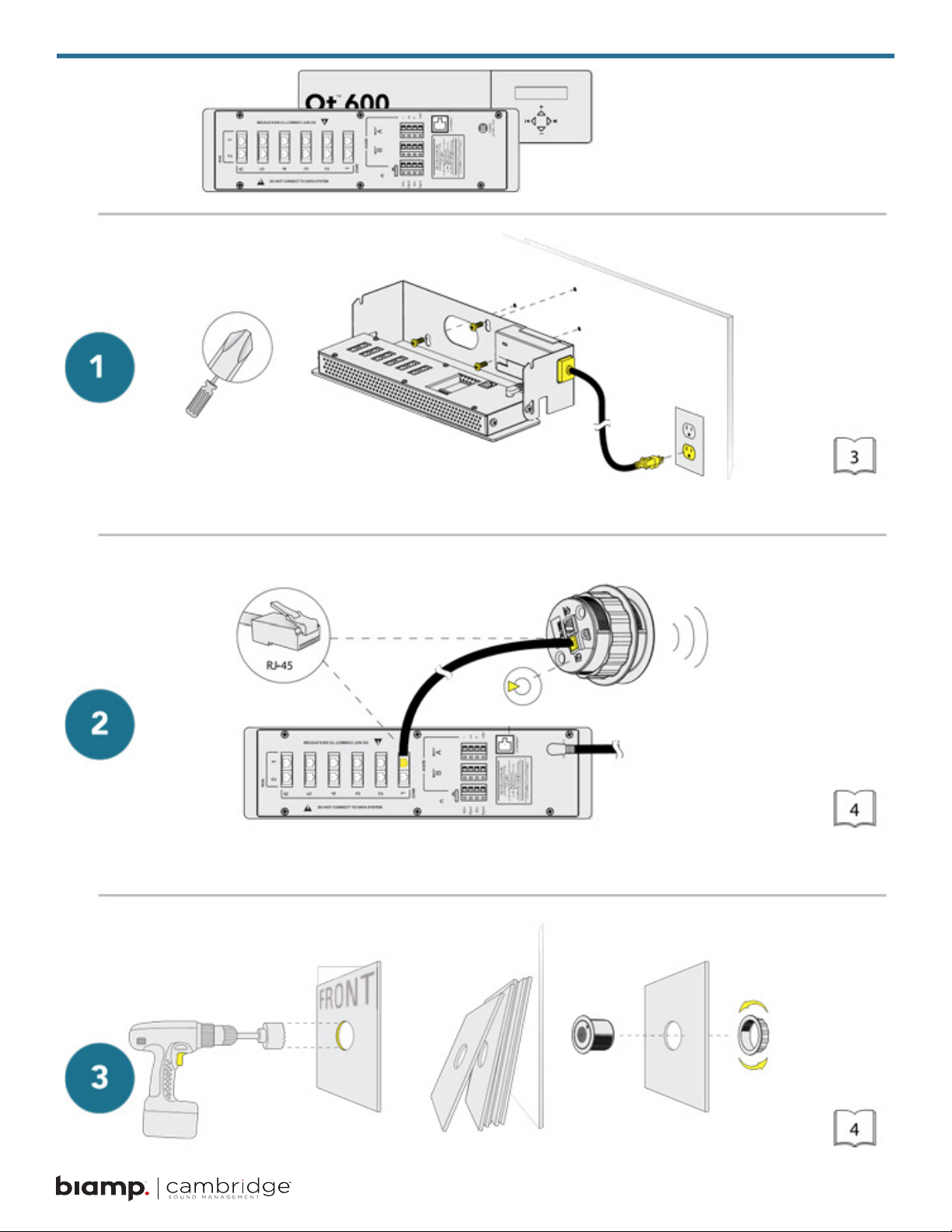
Wall Mount
Mount the bracket using the three screws and plastic anchors (mollies) provided. Use a 1/4 inch drill bit for the
anchor hole. See Figure 1.
Plastic anchors are #10-12 x 1 1/4 in with #10 x 1 1/2 screws.
NOTE: The control module hinges forward for wall mounting and cable installation. To hinge forward, loosen
screws A and B (see Figure 1) used to secure the module during shipping.
Check to see that the panel lock switch is in the UNLOCKED position.
Rack Mount
Attach optional rack mount brackets to each end of the control module.
NOTE: When rack mounted, the control module does not hinge forward.
10
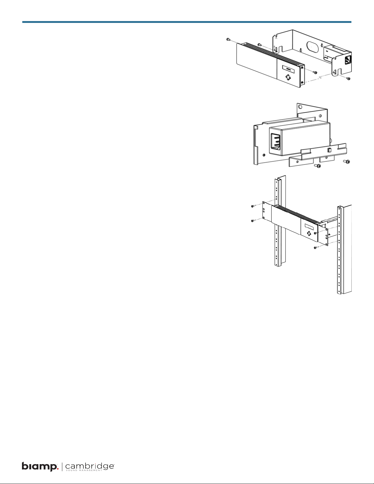
Step 1
Remove the QtPro and power supply bracket from wall mount
bracket.
Step 2
Reassemble power supply to right rack mount bracket using 6-32
black screws (included with bracket).
Step 3
Fasten left and right rack mount brackets to QtPro using the screws
removed in Step 1.
Step 4
Mount QtPro to 19” cabinet rail using 10-32 screws as shown
(included with bracket).
Installing the Qt Emitters
Important Considerations:
• Each run has a maximum of 60 Standard Emitters or
• 50 Active Emitters
• Each run should have a maximum length of 1000 ft (305 m).
• Each home run cable attached to the control module should be
labeled by zone # and run #. Adding a logical name (e.g. Marketing, Private Oces) is suggested. In addition, ll out “Home
Run Zone Destination Record” at the end of this Guide.
• Each zone has two identical outputs, run 1 and run 2. All emitters on run 1 and run 2 are controlled equally for each zone. All
emitters per zone must be the same type (Standard or Active).
• Each job-made cable should be manufactured according to
ANSI/TIA/EIA Standard 568-B. See custom cabling guidelines
on page 14.
• Job-made cables should be tested with a LAN tester before installation. Adjustable emitters should be set
for lower sound levels, within a zone, when sound level measurements show an acoustically loud subsection.
Standard Emitter Installation
1. Set the masking output level of all Standard Emitter zones to level 20.
2. Refer to the emitter layout and wiring diagram provided by the dealer for cable run connections by zone.
3. Run home run cables from control module to the location of the rst emitter for all runs in all zones.
11

4. Gather all ceiling tiles (per layout drawing) that are to receive emitters. Use the supplied hole saw to cut
holes in designated tiles. Cut all tiles from the front. (Dierent types of emitter housings are available to
attach in areas where there are no suspended ceiling tiles.)
5. Push the emitter through the front of the hole in tile and secure it by pushing down and twisting the locking
ring at the back of the emitter.
NOTE:
• The “tombstone” hook on the back of each emitter is next to the INPUT jack.
• This can help you nd the INPUT jack by touch.
• To adjust for unexpected obstacles such as sprinkler heads, each emitter maybe moved up
to 2 ft. (one tile or 0.6 m) in any direction.
6. Connect a run cable from the specied zone OUTPUT jack on the module to the INPUT jack of the rst
emitter. Listen to each emitter as it is connected. If you cannot hear its “whooshing” sound:
• Try a dierent emitter.
• Test all four previous cables for continuity and shorts. Repair any faulty cables.
• If there is a short, circuit protection will engage, and masking volume will shut o. Once the short is xed, the protection
state should clear itself in approximately ve minutes.
7. Connect the next OUTPUT cable to the emitter OUTPUT jack.
8. Run the cable to next designated tile specied on emitter layout and wiring diagram. Tie cables up to
structure or suspend from deck as required by local building code.
9. On the next emitter, connect this cable to the INPUT jack.
10. Repeat Steps 4 through 9 for the remaining emitters on the home run.
11. Set sound masking volume levels for each zone, using either the front panel controls or the software
interface. Set sound levels according to Table 1.
12. If a small area within a zone exhibits a perceived volume louder than the rest of the zone, due to a
dierence in acoustics, use the adjustable rocker switch on the back of each related emitter to turn the
volume down (by 3, 6, or 9 dB from the value set at the controller). See emitter spec sheet for more details.
Be sure to x any problems and hear the “whooshing” sound before installing the next emitter. If necessary see
the Error Codes section of this guide, found on page 32.
Active Emitter Installation
Before masking output volume can be set for zones with Active emitters, the emitter Type and Masking
Spectrum for those zones must to be congured within the MCS software. Refer to the MCS Operations
section later in this document.
NOTE:
• The input jack of each emitter bears this symbol and is located near the safety tie o.
• The output jack of each emitter bears this symbol.
12
 Loading...