

Page 1
AudiaEXPI
&
AudiaEXPO
Input & Output Expanders
Operation Manual
Biamp Systems | 9300 S.W. Gemini Drive | Beaverton, OR | 97008 | USA | +1.503.641.7287 | www.biamp.com
Page 2

AudiaEXPI - front & rear panels
AudiaEXPO - front & rear panels
Applications
Specifications
Block Diagrams
Warranty
CE Declaration
Safety Information
AudiaEXPI & AudiaEXPO
TABLE OF CONTENTS
Bl
ank
pg. 2
pg. 3
pgs. 4~11
pg. 12
pg. 13
pg. 14
pg. 15
pgs. 16~18
July, 2009
Page 3

AudiaEXPI & AudiaEXPO
y
INTRODUCTION
AudiaEXPI is an input expander for AUDIA
accepts eight mic/line analog audio inputs and provides eight channels of digital audio output via CobraNet®. AudiaEXPI can simply add inputs
to a centralized system, or it can extend system boundaries by providing inputs in remote locations. AudiaEXPI is represented as a block in
AUDIA software, for easy inclusion into any system design. AudiaEXPI may also be used to provide inputs to other CobraNet compliant s
or devices.
AudiaEXPI features include:
♦ 8 mic/line analog inputs on plug-in barrier strips
♦ front panel input level controls and peak indicators
♦ 24-bit A/D converters with 48kHz sample rate
♦ 8 channels of digital audio output via CobraNet
♦ rotary encoder with LCD for programming/setup
♦ included as block in AUDIA system design software
♦ may be used with any CobraNet compliant system
♦ CE marked and UL listed power source
®
, the benchmark in digital audio systems for demanding professional sound installations. AudiaEXPI
stems
AudiaEXPO is an output expander for AUDIA
AudiaEXPO accepts eight channels of digital audio input via CobraNet
®
, the benchmark in digital audio systems for demanding professional sound installations.
®
and provides eight line-level analog audio outputs. AudiaEXPO can
simply add outputs to a centralized system, or it can extend system boundaries by providing outputs in remote locations. AudiaEXPO is
represented as a block in AUDIA software, for easy inclusion into any system design. AudiaEXPO may also be used to provide outputs from
other CobraNet compliant systems or devices.
AudiaEXPO features include:
♦ 8 channels of digital audio input via CobraNet
♦ 24-bit D/A converters with 48kHz sample rate
♦ 8 line-level analog outputs on plug-in barrier strips
♦ front panel adjustable analog output level controls
♦ rotary encoder with LCD for programming/setup
♦ included as block in AUDIA system design software
♦ may be used with any CobraNet compliant system
♦ CE marked and UL listed power source
1
Page 4
AudiaEXPI - Front & Rear Panels
Peak Indicators (Inputs 1~8): These red LEDs will light whenever input channel signal levels reach +14dB (6dB below clipping). Use this
feature to aid in the adjustment of the Trim controls (see below).
Trims (Inputs 1~8): These screw-driver adjustable controls set the channel input gain (0dB ~ +60dB) to compensate for different source
levels. This gain range will accomodate most microphone or line level signals. For best performance, adjust these controls so the channel
Peak Indicators flash only on occasional peaks.
Rotary Encoder & LCD Display: This control and display are used for initial setup of the AudiaEXPI unit. When power is first applied to
the unit, the display will cycle through a product description, followed by a title screen. Press the control to enter setup. Rotate the control
to make a selection, then press the control again to edit that selection. Additional levels of selection may be available using this same
routine. Some edits will require a choice of 'OK' or 'CANCEL. Some selections are only informational, and cannot be edited. Select
'BACK' to return to a previous level, and select '→' to advance. Primary selections are as follows
: BUNDLE NUMBER (CobraNet bundle
number to logic input assignments); COBRANET LATENCY (dependent upon CobraNet firmware); PHANTOM POWER (assigns
phantom power to inputs); PASSWORD PROTECT (prohibits unauthorized tampering); TITLE DISPLAY (personalized: 2 lines with 8
characters each); ABOUT (serial#, version#, and Ethernet address information).
Mic/Line Inputs: These eight mic/line analog audio inputs are provided on balanced plug-in barrier-strip connectors. For unbalanced
input, wire high to (+) and ground to both (-) & (
d
). For use with condenser microphones, +48 volt phantom power is available at these
inputs (see Rotary Encoder above).
Logic Inputs: These eight Logic Inputs allow remote control of CobraNet bundle number assignment (see CobraNet below). Bundle
numbers can be assigned to Logic Inputs using the front panel Rotary Encoder (see above), and can then be selected via external contactclosures (wired from the corresponding logic inputs to ground). Bundle numbers are used to route digital audio signals to specific devices
in a system network.
CobraNet: These two RJ45 connectors provide the CobraNet digital audio interface. CobraNet allows multiple AUDIA units to share
digital audio (and DSP resources) on a system network. This also allows AUDIA units to be used with CobraNet compliant devices from
other manufacturers. A 10/100Base-T Ethernet switch (not hub) is required when networking multiple units. The maximum distance
between any unit and an Ethernet switch is 100 meters. Additional Ethernet switches, or even fiber-optics, can be used to further extend
distances between units on a system network. The primary and secondary CobraNet ports are redundant. CobraNet supports 64
channels of digital audio (32-in & 32-out) over Fast Ethernet, using CAT-5 cable. CobraNet transmits (32) channels of digital audio on (4)
'bundles' of (8) channels each. The same is true for receiving digital audio over CobraNet. Bundle numbers are used to determine where
digital audio is transmitted and received. Typically, 'unicast' bundle numbers (256~61,439) are used to exchange digital audio between two
specific devices. With 'unicast' bundles, each CobraNet device can transmit to no more than (4) other devices within a network. With
'multicast' bundle numbers (1~255), digital audio can be exchanged with multiple devices. Due to network delay, CobraNet has a limitation
of seven (7) 'hops' (one-way transmissions) within a network.
In order to integrate AudiaEXPI into a AUDIA system, an EXPI (or CobraNet) input block must first be placed into the design layout.
AUDIA units intended to receive digital audio from the AudiaEXPI must have their CobraNet jacks connected to the same network. Both
the AudiaEXPI unit (hardware) and the EXPI input block (software) must be assigned matching bundle numbers, before digital audio can
be successfully exchanged. AudiaEXPI bundle number assignment can be changed in real-time to allow routing of digital audio to different
EXPI input blocks within the system. CobraNet Latency settings must be identical in all devices, system-wide. Also, unicast and multicast
bundle numbers can be used to route digital audio to individual or multiple EXPI input blocks. Similar considerations may also apply when
using AudiaEXPI with other CobraNet compliant systems or devices. AudiaEXPI and AudiaEXPO can exchange digital audio directly
(outside of a system network) using either a simple 'cross-over' CAT5 cable or an Ethernet switch.
2
Page 5
AudiaEXPO - Front & Rear Panels
Levels (Outputs 1~8): These screw-driver adjustable controls set the channel output gain (-70dB ~ 0dB) to provide appropriate signal
levels to any subsequent audio equipment.
Rotary Encoder & LCD Display: This control and display are used for initial setup of the AudiaEXPI unit. When power is first applied to
the unit, the display will cycle through a product description, followed by a title screen. Press the control to enter setup. Rotate the control
to make a selection, then press the control again to edit that selection. Additional levels of selection may be available using this same
routine. Some edits will require a choice of 'OK' or 'CANCEL. Some selections are only informational, and cannot be edited. Select
'BACK' to return to a previous level, and select '→' to advance. Primary selections are as follows
: BUNDLE NUMBER (CobraNet bundle
number to logic input assignments); COBRANET LATENCY (dependent upon CobraNet firmware); PASSWORD PROTECT (prohibits
unauthorized tampering); TITLE DISPLAY (personalized: 2 lines with 8 characters each); ABOUT (serial#, version#, and Ethernet
address information).
Line Outputs: These eight line-level analog audio outputs are provided on balanced plug-in barrier-strip connectors. For unbalanced
output, wire high to (+) and ground to (
d
), leaving (-) un-connected.
Logic Inputs: These eight Logic Inputs allow remote control of CobraNet bundle number assignment (see CobraNet below). Bundle
numbers can be assigned to Logic Inputs using the front panel Rotary Encoder (see above), and can then be selected via external contactclosures (wired from the corresponding logic inputs to ground). Bundle numbers are used to route digital audio signals to specific devices
in a system network.
CobraNet: These two RJ45 connectors provide the CobraNet digital audio interface. CobraNet allows multiple AUDIA units to share
digital audio (and DSP resources) on a system network. This also allows AUDIA units to be used with CobraNet compliant devices from
other manufacturers. A 10/100Base-T Ethernet switch (not hub) is required when networking multiple units. The maximum distance
between any unit and an Ethernet switch is 100 meters. Additional Ethernet switches, or even fiber-optics, can be used to further extend
distances between units on a system network. The primary and secondary CobraNet ports are redundant. CobraNet supports 64
channels of digital audio (32-in & 32-out) over Fast Ethernet, using CAT-5 cable. CobraNet transmits (32) channels of digital audio on (4)
'bundles' of (8) channels each. The same is true for receiving digital audio over CobraNet. Bundle numbers are used to determine where
digital audio is transmitted and received. Typically, 'unicast' bundle numbers (256~61,439) are used to exchange digital audio between two
specific devices. With 'unicast' bundles, each CobraNet device can transmit to no more than (4) other devices within a network. With
'multicast' bundle numbers (1~255), digital audio can be exchanged with multiple devices. Due to network delay, CobraNet has a limitation
of seven (7) 'hops' (one-way transmissions) within a network.
In order to integrate AudiaEXPO into a AUDIA system, an EXPO (or CobraNet) output block must first be placed into the design layout.
AUDIA units intended to transmit digital audio to the AudiaEXPO must have their CobraNet jacks connected to the same network. Both the
AudiaEXPO unit (hardware) and the EXPO output blo ck (software) must be assigned matching bundle numbers, before digital audio can
be successfully exchanged. AudiaEXPO bundle number assignment can be changed in real-time to allow access to digital audio from
different EXPO output blocks within the system. CobraNet Latency settings must be identical in all devices, system-wide. Also, unicast
and multicast bundle numbers can be used to access digital audio from individual or multiple EXPO output blocks. Similar considerations
may apply when using AudiaEXPO with other CobraNet compliant systems or devices. AudiaEXPI and AudiaEXPO can exchange digital
audio directly (outside of a system network) using either a simple 'cross-over' CAT5 cable or an Ethernet switch.
3
Page 6
APPLICATIONS
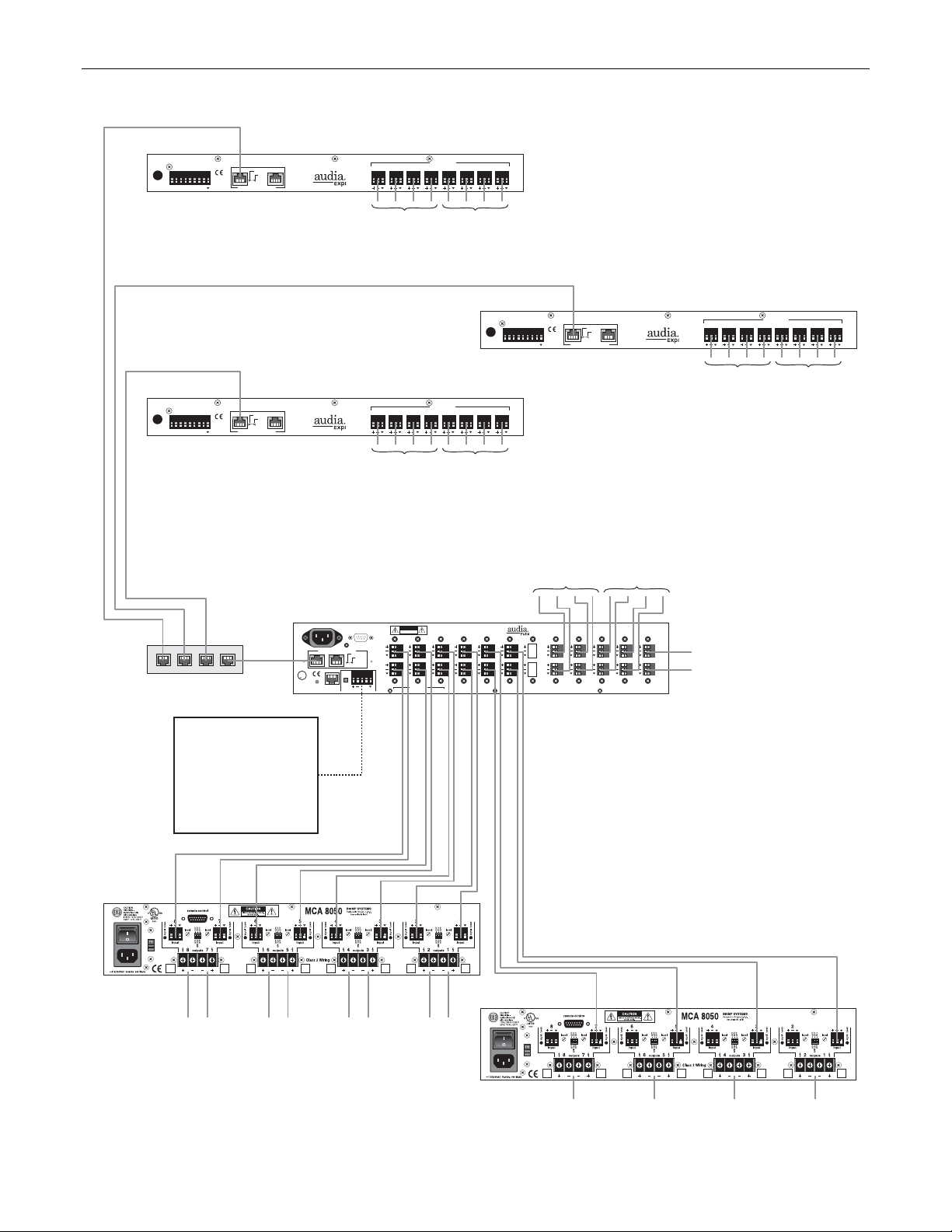
Hotel with Sound Reinforcement in Multiple Banquet/Conference Rooms
This application demonstrates the use of AUDIA in a
hotel conference/banquet facility. This is a
networked system using one AudiaFLEX 10x12CM
left
stereo
speaker
unit and three AudiaEXPI 8-Input Expander units
(forty-two inputs, twelve outputs, CobraNet). An
example system diagram is shown on the next page.
Each room has four microphones and two stereo line
inputs, which are connected to an AudiaEXPI located
within the room. This is beneficial because stereo
line input signals are typically 'unbalanced' and, as
such, should not be routed over long distances. The
AudiaEXPI converts these signals to digital audio,
and transmits them back to the main equipment rack
via CobraNet. Additionally, CobraNet affords the
necessary isolation to help avoid ground loops
stereo
input
#1
left
stereo
speaker
between active components within the individual
rooms and back at the main equipment rack.
CobraNet also saves on the labor and expense of
wiring, by transmitting all signals from a given room
over a single CAT5 cable.
Only three of the rooms utilize an AudiaEXPI locally.
The fourth room houses the main equipment rack,
which includes an AudiaFLEX 10x12CM. The
AudiaFLEX unit accommodates the eight inputs from
stereo
input
#1
this room, as well as two inputs from centralized
paging and background music. The AudiaFLEX unit
also provides twelve system outputs: mono speech
and stereo program for each of the four rooms.
These outputs are feeding the two MCA8050 multichannel amplifiers.
One MCA8050 amplifier has eight channels which are operating as four stereo pairs, providing up to 50 watts per channel to drive the
stereo program speakers in each of the four rooms. The other MCA8050 amplifier has eight channels which have been bridged in pairs,
essentially creating four channels of 100 watts each. With four TDT100 transformers installed internally, this MCA8050 is prepared to drive
the (speech related) 70 volt distibuted speaker system in each of the four rooms.
CobraNet from the AudiaEXPI units to the AudiaFLEX unit is tied together through an Ethernet switch. This allows sharing of digital audio
signals (CobraNet) on a network. The maximum distance between any AUDIA unit and an Ethernet switch is 300 feet. Therefore, this
system can span up to 600 feet between the main equipment rack and any of the rooms. Additional Ethernet switches, or even fiberoptics, can be used to further extend distances between units on the network.
All mixing and processing of signals is done back at the AudiaFLEX unit in the main equipment rack. In the system design, each room is
provided with an Auto Mixer (4x1) for the microphones and a Router (4x2) for stereo source selection. A Room Combiner allows proper
sharing of audio and control data amongst the Auto Mixers, and a Matrix Mixer (8x8) is provided to facilitate proper stereo source routing
for each of the various room configurations. Duckers allow page-override of local and backgound music signals. Levelers are utilized on
all microphone inputs (to provide consistent volume levels), and equalizers are utilized at all outputs (to compensate for room acoustics
and enhance intelligibility).
Various remote control options are available. Volume 8, Select 8, and Volume/Select 8 rotary encoder panels may be used to provide
volume, source selection, and even room combining functions. A Logic Box could instead provide room combining via external switches
(on the room partitions or on a custom control panel), and would also allow control of external equipment (such as lighting, speakers,
sources, etc.). Control behavior is programmable, and can be made to change automatically to fit different system configurations. For
example, volume control and source selection can follow room combining.
Room A
distributed 70V
ceiling speakers
microphones #1~4
Room C
distributed 70V
ceiling speakers
microphones #1~4
central
paging
microphone
right
stereo
speaker
right
stereo
speaker
stereo
input
stereo
input
left
stereo
speaker
stereo
#2
#2
input
#1
stereo
input
#1
left
stereo
speaker
Room B
distributed 70V
ceiling speakers
microphones #1~4
Room D
distributed 70V
ceiling speakers
microphones #1~4
background music service
Channel 5
right
stereo
speaker
right
stereo
speaker
stereo
input
stereo
input
#2
#2
4
Page 7
APPLICATIONS
AudiaEXPI
BIAMP SYSTEMS
designed and assembled in the USA
www.biamp.com
27V
~
50/60 Hz
logic inputs
25 watts
class 2 wiring
12345678
AudiaEXPI
BIAMP SYSTEMS
designed and assembled in the USA
www.biamp.com
27V
~
50/60 Hz
logic inputs
25 watts
class 2 wiring
12345678
in use / conductor
link / activity
LEDs
U.S. pat. no. 4,922,536
CobraNet® connections only
in use / conductor
link / activity
LEDs
U.S. pat. no. 4,922,536
CobraNet® connections only
secondaryprimary
secondaryprimary
8
Room A
inputs
8
Room C
inputs
mic/line inputs
7 6 5 4 3 2 1
stereo
inputs
1 & 2
7 6 5 4 3 2 1
stereo
inputs
1 & 2
microphone
inputs
1~4
mic/line inputs
microphone
inputs
1~4
AudiaEXPI
BIAMP SYSTEMS
designed and assembled in the USA
www.biamp.com
27V
~
50/60 Hz
logic inputs
25 watts
class 2 wiring
12345678
in use / conductor
link / activity
LEDs
U.S. pat. no. 4,922,536
CobraNet® connections only
secondaryprimary
Room B
inputs
8
mic/line inputs
7 6 5 4 3 2 1
stereo
microphone
inputs
1 & 2
inputs
1~4
CobraNet
MCA8050
EtherNet Switch
remote control options:
Volume 8, Select 8,
Volume/Select 8,
Logic Box
(source volumes,
room combining,
page routing, etc.)
AudiaFLEX 10x12 CM
100-240V
~
50/60Hz
150 Watts
U
CUS
R
L
LISTED
52SJ
CobraNet® connections only
primary
link
Ethernet
secondary
Serial Control Port
in use / conductor
LEDs
U.S. pat. no. 4,922,536
24VDC
1.5A
term hi lo
Remote Control Bus
link / activity
RISK OF ELECTRICAL SHOCK.
In 23
Out 1
In 24
Out 2
CAUTION
DO NOT OPEN.
stereo
Room D
inputs
inputs
Installation Instructions: Telephone Interface TI-2
This device must be installed by qualified, trained personnel.
Connections to the telephone network must be made with
#26 AWG solid copper wire for continued safety.
In 17
In 19
In 21
Out 7
Out 5
Out 3
In 18
In 20
In 22
Out 8
Out 6
Out 4
class 2 wiring
BLACK connectors = OUTPUTSYELLOW connectors = AMP OUTPUTS GREEN connectors = INPUTS
In 11
In 13
In 15
Out 13
Out 11
Out 9
In 12
In 14
In 16
Out 14
Out 12
Out 10
ORANGE connectors = AEC INPUTS
1 & 2
BIAMP SYSTEMS MODEL TI-2
US:6RMBR00BAUDIATI2
IC:3184A-AUDIATI-2
In 9
Out 15
In 10
Out 16
microphone
In 5
In 7
Out 19
Out 17
In 6
In 8
Out 20
Out 18
inputs
1~4
BIAMP SYSTEMS
designed and assembled in the USA
www.biamp.com
In 3
Out 21
In 4
Out 22
In 1
central paging microphone
Out 23
In 2
background music service
Out 24
Room D
stereo
speakers
Room C
stereo
speakers
Room B
stereo
speakers
Room A
stereo
speakers
MCA8050
5
Room D
ceiling
speakers
Room C
ceiling
speakers
Room B
ceiling
speakers
Room A
ceiling
speakers
Page 8

APPLICATIONS
Courthouse with Multiple Courtrooms and Hard-Disk Court Recording
This application demonstrates the use of AUDIA in a
modern courthouse. This is a networked system
using two AudiaFLEX 20x4CM units and two
AudiaEXPO 8-Output Expander units (forty inputs,
twenty-four outputs, CobraNet). An example system
diagram is shown on the next page.
Each courtroom is shown as having ten
microphones. AUDIA inputs accept microphone or
line-level signals equally well, so some inputs could
instead be from sources such as playback of
recorded evidence. Inputs from the four courtrooms
are connected to the two AudiaFLEX units, which are
located in a local equipment closet. Each
AudiaFLEX unit accommodates inputs from two of
the courtrooms, and provides four system outputs.
In this case, one unit provides the outputs necessary
to feed a hearing assistance system in each of the
courtrooms. The other unit is providing the outputs
needed for sound reinforcement. These outputs are
feeding an MCA8050 multi-channel amplifier.
The MCA8050 amplifier has eight channels which
have been bridged in pairs, essentially creating four
channels of 100 watts each. With four TDT100
transformers installed internally, the MCA8050 is
prepared to drive the 70 volt distibuted speaker
system in each of the four courtrooms.
CobraNet and Ethernet from both AudiaFLEX units
are tied together through an Ethernet switch. This
allows sharing of digital audio signals (CobraNet)
4-track
hard-disk
court recorder
and control data (Ethernet) on a network.
Connected to the same Ethernet switch, and
functioning as part of the same network, are two
AudiaEXPO units. These two AudiaEXPO units are
physically located in a central computer/recording office. The maximum distance between any AUDIA unit and an Ethernet switch is 300
feet. Therefore, this system can span up to 600 feet between the equipment closet and the computer/recording office. Additional Ethernet
switches, or even fiber-optics, can further extend distances between units on the network.
Each AudiaEXPO receives eight channels of digital audio via CobraNet, over a single CAT5 cable. These eight channels of digital audio
are then converted to analog audio, and appear on eight separate output connections. Each AudiaEXPO provides the appropriate
channels of audio for two of the four court recording systems. Mixing and processing of these signals (to achieve proper microphone/track
assignment and consistent recording levels) has already be accomplished back at the AudiaFLEX units.
Design example: Recording signals are not gated or equalized, but Levelers are employed to ensure consistent levels and intelligibility.
Matrix Mixers used to provide the following input-to-track assignments: Judge & Sidebar (track 1); Witness, Evidence, & Clerk (track 2);
Defense, Prosecution, Podium, & Wireless (track 3); Jury (track 4). Mixing and processing of signals for hearing assistance and sound
reinforcement have also been accomplished within the AudiaFLEX units. These are the same input signals that feed the recorders, but in
this case they are mixed and gated appropriately using Auto Mixers. Levelers are then utilized at these outputs (to provide consistent
output volume), and equalizers are utilized at the sound reinforcements outputs only (to compensate for courtroom acoustics).
Various remote control options are available. Volume 8, Select 8, and Volume/Select 8 rotary encoder panels may be used to provide
volume, override, sidebar, and other such functions. A Logic Box would allow individual microphone privacy switches and/or control of
external functions (such as camera presets or speaker relays). External switches can even be connected to the AudiaEXPO logic inputs,
to allow remote selection of courtroom-to-recorder assignments (via CobraNet bundle assignment).
Courtroom A
distributed 70V
speaker system
microphones #1~10
Courtroom C
distributed 70V
speaker system
microphones #1~10
4-track
hard-disk
court recorder
4-track
hard-disk
court recorder
Courtroom B
distributed 70V
speaker system
microphones #1~10
Courtroom D
distributed 70V
speaker system
microphones #1~10
4-track
hard-disk
court recorder
6
Page 9

APPLICATIONS
AudiaEXPO
50/60 Hz
25 watts
class 2 wiring
27V
~
12345678
BIAMP SYSTEMS
designed and assembled in the USA
www.biamp.com
logic inputs
primary
in use / conductor
LEDs
U.S. pat. no. 4,922,536
CobraNet® connections only
secondary
link / activity
line outputs
8
7 6 5 4 3 2 1
remote control option:
switch assignment of
courtrooms/recorders
AudiaFLEX 20x4 CM
100-240V
~
L
CobraNet® connections only
primary
link
Ethernet
secondary
Serial Control Port
in use / conductor
LEDs
U.S. pat. no. 4,922,536
24VDC
1.5A
term hi lo
Remote Control Bus
RISK OF ELECTRICAL SHOCK.
In 23
link / activity
Out 1
In 24
Out 2
50/60Hz
150 Watts
U
CUS
R
LISTED
52SJ
Courtroom B mics
Installation Instructions: Telephone Interface TI-2
CAUTION
This device must be installed by qualified, trained personnel.
Connections to the telephone network must be made with
DO NOT OPEN.
#26 AWG solid copper wire for continued safety.
In 19
In 21
Out 5
Out 3
In 20
In 22
Out 6
Out 4
class 2 wiring
BLACK connectors = OUTPUTSYELLOW connectors = AMP OUTPUTS GREEN connectors = INPUTS
In 13
In 15
In 17
Out 11
Out 9
Out 7
In 14
In 16
In 18
Out 12
Out 10
Out 8
Court B
recorder
Courtroom A mics
BIAMP SYSTEMS MODEL TI-2
US:6RMBR00BAUDIATI2
IC:3184A-AUDIATI-2
In 7
In 9
In 11
Out 17
Out 15
Out 13
In 8
In 10
In 12
Out 18
Out 16
Out 14
ORANGE connectors = AEC INPUTS
Court A
recorder
AudiaEXPO
BIAMP SYSTEMS
designed and assembled in the USA
www.biamp.com
27V
~
50/60 Hz
logic inputs
25 watts
class 2 wiring
12345678
remote control option:
switch assignment of
courtrooms/recorders
BIAMP SYSTEMS
designed and assembled in the USA
www.biamp.com
In 1
In 3
In 5
Out 23
Out 21
Out 19
In 2
In 4
In 6
Out 24
Out 22
Out 20
primary
in use / conductor
link / activity
LEDs
U.S. pat. no. 4,922,536
CobraNet® connections only
line outputs
8
secondary
7 6 5 4 3 2 1
Court D
recorder
Court C
recorder
Courtrooms A~D
Ethernet
EtherNet Switch
CobraNet
EtherNet Switch
hearing assist
remote control options:
Volume 8, Select 8,
Volume/Select 8,
Logic Box
(volume, override,
side-bar, masking,
muting, etc.)
AudiaFLEX 20x4 CM
100-240V
~
CobraNet® connections only
primary
link
Ethernet
secondary
Serial Control Port
in use / conductor
LEDs
U.S. pat. no. 4,922,536
24VDC
1.5A
term hi lo
Remote Control Bus
link / activity
50/60Hz
150 Watts
U
CUS
R
L
LISTED
52SJ
MCA8050
Courtroom D
speakers
7
CAUTION
RISK OF ELECTRICAL SHOCK.
DO NOT OPEN.
In 23
Out 1
In 24
Out 2
class 2 wiring
Courtroom D mics
Installation Instructions: Telephone Interface TI-2
This device must be installed by qualified, trained personnel.
Connections to the telephone network must be made with
#26 AWG solid copper wire for continued safety.
In 19
In 21
Out 5
Out 3
In 20
In 22
Out 6
Out 4
BLACK connectors = OUTPUTSYELLOW connectors = AMP OUTPUTS GREEN connectors = INPUTS
Courtroom C
In 13
In 15
In 17
Out 11
Out 9
Out 7
In 14
In 16
In 18
Out 12
Out 10
Out 8
Courtroom B
speakers
Courtroom C mics
BIAMP SYSTEMS MODEL TI-2
US:6RMBR00BAUDIATI2
IC:3184A-AUDIATI-2
In 9
In 11
Out 15
Out 13
In 10
In 12
Out 16
Out 14
ORANGE connectors = AEC INPUTS
speakers
In 5
In 7
Out 19
Out 17
In 6
In 8
Out 20
Out 18
Courtroom A
speakers
BIAMP SYSTEMS
designed and assembled in the USA
www.biamp.com
In 3
Out 21
In 4
Out 22
In 1
Out 23
In 2
Out 24
Page 10

APPLICATIONS
Hospital with Multiple Zones of Paging, Messaging, and Background Music
This application demonstrates the use of AUDIA in a
multi-zone hospital building. This is a networked
system using one AudiaFLEX 8x8CM unit and three
AudiaEXPO 8-Output Expander units (eight inputs,
thirty-two outputs, CobraNet). An example system
Zone 1
speakers
Zone 2
speakers
Zone 3
speakers
diagram is shown on the back page.
All inputs (paging microphone, message repeater,
background music, and telephone system) reside on
the first floor of the building, and are connected to
the AudiaFLEX unit located there. The AudiaFLEX
Zone 1
speakers
Zone 2
speakers
Zone 3
speakers
unit also provides the outputs necessary to feed the
eight zones on the first floor. An AudiaEXPO unit is
located on each of the other floors, and provides the
corresponding zone outputs for that floor.
The AudiaFLEX unit distributes the appropriate
signals to the AudiaEXPO units on the other floors
Zone 1
speakers
Zone 2
speakers
Zone 3
speakers
as digital audio via CobraNet. This is beneficial
because some of the input sources are 'unbalanced'
and, as such, should not be routed over long
distances. Additionally, CobraNet affords the
necessary isolation to help avoid ground loops
between the active components located on different
Zone 1
speakers
Zone 2
speakers
Zone 3
speakers
floors. CobraNet also saves on the labor and
expense of wiring, by transmitting all eight of the
associated zone output signals to a given floor over a
single CAT5 cable.
The zone outputs on each of the floors are
connected to an MCA8050 multi-channel amplifier,
central
paging
microphone
located in the same equipment rack as the
AudiaFLEX or AudiaEXPO unit. Each MCA8050
amplifier has eight channels, delivering 50 watts of
digital message repeater
power per channel. With eight TDT50 transformers
installed internally, each MCA8050 is prepared to
drive the eight 70 volt distibuted speaker systems on that floor.
CobraNet from the AudiaFLEX unit to the AudiaEXPO units is tied together through an Ethernet switch. This allows sharing of digital audio
signals (CobraNet) on a network. The maximum distance between any AUDIA unit and an Ethernet switch is 300 feet. Therefore, this
system can span up to 600 feet between the first floor equipment rack and any of the other floors. Additional Ethernet switches, or even
fiber-optics, can be used to further extend distances between units on the network.
All mixing and processing of signals is accomplished within the AudiaFLEX unit on the first floor. In the system design, the paging
microphone is fed to a Router (1x32) for assignment to the individual zones. The message repeater is fed to a Router (1x4) for assignment
to the four floors. The two background music inputs are both fed to four separate Routers (2x1) for source selection on each of the four
floors. Telephone paging is fed to a set of four Duckers (one for each floor) to provide page-override of the selected background music on
that floor. Output from the message Router is fed to a second set of four Duckers (one for each floor) to provide message-override of the
telephone and music signals on that floor. Finally, output from the microphone Router is fed to a bank of thirty-two Duckers (one for each
zone) to provide master page-override of all other signals in any selected zones. Levelers are utilized on all paging and message inputs
(to provide consistent volume levels), and equalizers are utilized at all outputs (to compensate for building acoustics and enhance
intelligibility).
Various remote control options are available. Volume 8, Select 8, and Volume/Select 8 rotary encoder panels may be used to provide
volume, source selection, and even page routing functions. Two Logic Box control devices could instead provide forty logic inputs, which
would allow all page/message routing and music source selection to be accomplished using external switches on custom control panels.
4th Floor
Zone 4
speakers
Zone 4
speakers
Zone 4
speakers
Zone 4
speakers
background music service
background music service
speakers
3rd Floor
speakers
2nd Floor
speakers
1st Floor
speakers
Channel 3
Channel 5
Zone 5
Zone 5
Zone 5
Zone 5
Zone 6
speakers
Zone 6
speakers
Zone 6
speakers
Zone 6
speakers
Zone 7
speakers
Zone 7
speakers
Zone 7
speakers
Zone 7
speakers
1st Floor
telephone page
3rd Floor
telephone page
Zone 8
speakers
Zone 8
speakers
Zone 8
speakers
Zone 8
speakers
2nd Floor
telephone page
4th Floor
telephone page
8
Page 11

APPLICATIONS
AudiaEXPO
BIAMP SYSTEMS
designed and assembled in the USA
www.biamp.com
27V
~
50/60 Hz
logic inputs
25 watts
class 2 wiring
12345678
MCA8050
primary
in use / conductor
link / activity
LEDs
U.S. pat. no. 4,922,536
CobraNet® connections only
secondary
line outputs
8
7 6 5 4 3 2 1
4th Floor
speaker
zones
AudiaEXPO
BIAMP SYSTEMS
designed and assembled in the USA
www.biamp.com
27V
~
50/60 Hz
logic inputs
25 watts
class 2 wiring
12345678
MCA8050
2nd Floor
speaker
zones
primary
in use / conductor
LEDs
U.S. pat. no. 4,922,536
CobraNet® connections only
12345678
AudiaEXPO
27V
50/60 Hz
25 watts
class 2 wiring
~
12345678
BIAMP SYSTEMS
designed and assembled in the USA
www.biamp.com
logic inputs
primary
in use / conductor
link / activity
LEDs
U.S. pat. no. 4,922,536
CobraNet® connections only
secondary
line outputs
8
7 6 5 4 3 2 1
MCA8050
3rd Floor
speaker
12345678
zones
line outputs
8
secondary
link / activity
7 6 5 4 3 2 1
central paging microphone
digital message repeater
background music service
background music service
12345678
1st Floor telephone page
2nd Floor telephone page
3rd Floor telephone page
4th Floor telephone page
AudiaFLEX 8x8 CM
100-240V
~
CobraNet® connections only
primary
link
Ethernet
secondary
Serial Control Port
in use / conductor
LEDs
U.S. pat. no. 4,922,536
24VDC
1.5A
term hi lo
Remote Control Bus
link / activity
50/60Hz
150 Watts
U
CUS
R
L
LISTED
52SJ
RISK OF ELECTRICAL SHOCK.
In 23
Out 1
In 24
Out 2
CAUTION
DO NOT OPEN.
class 2 wiring
Installation Instructions: Telephone Interface TI-2
This device must be installed by qualified, trained personnel.
Connections to the telephone network must be made with
#26 AWG solid copper wire for continued safety.
In 21
Out 3
In 22
Out 4
In 15
In 17
In 19
Out 9
Out 7
Out 5
In 16
In 18
In 20
Out 10
Out 8
Out 6
BLACK connectors = OUTPUTSYELLOW connectors = AMP OUTPUTS GREEN connectors = INPUTS
BIAMP SYSTEMS MODEL TI-2
US:6RMBR00BAUDIATI2
IC:3184A-AUDIATI-2
In 9
In 11
In 13
Out 15
Out 13
Out 11
In 14
Out 12
In 12
Out 14
ORANGE connectors = AEC INPUTS
In 10
Out 16
BIAMP SYSTEMS
designed and assembled in the USA
www.biamp.com
In 1
In 3
In 5
In 7
Out 23
Out 21
Out 19
Out 17
In 8
Out 18
In 2
In 4
In 6
Out 24
Out 22
Out 20
CobraNet
EtherNet Switch
remote control options:
Volume 8, Select 8,
Volume/Select 8,
Logic Box
(zone volume,
music selection,
page routing, etc.)
MCA8050
1st Floor
speaker
zones
9
12345678
Page 12

APPLICATIONS
Theater with Live Mixing Console and Multiple Speaker Zones
This application demonstrates the use of AUDIA in a
live-performance theater. This is a networked
system using one AudiaFLEX 2x8CM unit, three
AudiaEXPI 8-Input Expander units, and two
AudiaEXPO 8-Output Expander units (twenty-six
inputs, twenty-four outputs, CobraNet). An example
system diagram is shown on the back page.
Sixteen stage microphones are connected to the
inputs of two AudiaEXPI units, which are located
backstage. These sixteen signals then appear at the
outputs of two AudiaEXPO units, which are located
near the mixing console. The console is used to mix
these signals (plus any local source signals, such as
effects and playback) to as many as eight different
outputs: Left/Center/Right (front-of-house), UnderBalcony (rear-of-house), Stage Monitors (1 & 2),
Lobby, and Backstage. These outputs are
connected to a another AudiaEXPI unit, which is
located near the mixing console. These eight signals
then appear backstage at an AudiaFLEX unit, which
provides signal processing for each of the outputs
before feeding MCA8050 and MCA8150 power
amplifiers located in the same equipment rack.
The MCA8050 amplifier has eight channels bridged
in pairs, creating four channels of 100 watts each.
These outputs are driving the Backstage, Lobby, and
Monitor speaker systems. The MCA8150 amplifier
also has eight channels which have been bridged in
pairs, providing four channels of 300 watts each.
These outputs are driving the Left/Center/Right and
Under-Balcony speakers. TDT300 and TDT100
transformers are installed internally for outputs
driving 70V distributed speaker systems.
The AudiaFLEX unit also receives input from an emergency paging microphone (located in the office), and from an announcement
microphone (located backstage). These two signals can be routed (with override capability) to any of the eight outputs. Example:
Emergency paging may be desired at all outputs, while announcements may be routed to the Lobby or Backstage as necessary. CobraNet
from the six AUDIA units is tied together through an Ethernet switch. This allows sharing of digital audio signals on a network. The
maximum distance between any AUDIA unit and an Ethernet switch is 300 feet. Therefore, this system can span up to 600 feet between
the stage and mixing position. Additional Ethernet switches, or even fiber-optics, can be used to further extend distances between units on
the network. An added benefit to CobraNet is that it affords the necessary isolation to help avoid ground loops between active components
in different locations. CobraNet also saves on the labor and expense of wiring, by transmitting eight channels of digital audio over a single
CAT5 cable.
Of course, all live mixing is done at the console. The AUDIA network provides transportation, routing, and processing of the signals.
AudiaEXPI and AudiaEXPO units act as a 'digital snake', transmitting digital audio between the stage and mixing position. The AudiaFLEX
unit provides routing and remote control capabilites, as well as signal processing for the speaker outputs. In the system design, the
emergency and announcement microphone inputs employ Levelers (for consistent volume), Routers (for output assignment), and Duckers
(for page-override). At the outputs, processing includes Equalizers (to compensate for acoustics), Comp/Limiters (to control peaks), and
Delays (for speaker zone alignment).
Various remote control options are available. Volume 8, Select 8, and Volume/Select 8 rotary encoder panels may be used to provide
volume, preset selection, and even page routing functions. A Logic Box allows system control via external switches, or control of external
equipment from the system.
Stage
microphones #1~16
stage monitor mixes
Backstage
distributed 70V
speaker system
announcement
microphone
emergency
paging
microphone
Auditorium
left - center - right
main speakers
under-balcony speakers
Lobby
distributed 70V
speaker system
mixing console
10
Page 13

APPLICATIONS
AudiaEXPI
50/60 Hz
25 watts
class 2 wiring
27V
~
BIAMP SYSTEMS
designed and assembled in the USA
www.biamp.com
logic inputs
12345678
in use / conductor
link / activity
LEDs
U.S. pat. no. 4,922,536
CobraNet® connections only
secondaryprimary
8
mic/line inputs
7 6 5 4 3 2 1
AudiaEXPI
BIAMP SYSTEMS
designed and assembled in the USA
www.biamp.com
27V
~
50/60 Hz
logic inputs
25 watts
class 2 wiring
12345678
CobraNet
EtherNet Switch
remote control options:
Volume 8, Select 8,
Volume/Select 8,
Logic Box
(volumes, presets,
muting, scenes,
routing, etc.)
in use / conductor
link / activity
LEDs
U.S. pat. no. 4,922,536
CobraNet® connections only
secondaryprimary
AudiaFLEX 2x8 CM
100-240V
~
50/60Hz
150 Watts
primary
U
CUS
R
L
LISTED
52SJ
CobraNet® connections only
secondary
link
Ethernet
from Stage mics 1~8
8
mic/line inputs
7 6 5 4 3 2 1
from Stage mics 9~16
Serial Control Port
in use / conductor
LEDs
U.S. pat. no. 4,922,536
24VDC
1.5A
term hi lo
Remote Control Bus
link / activity
RISK OF ELECTRICAL SHOCK.
In 23
Out 1
In 24
Out 2
CAUTION
DO NOT OPEN.
In 21
Out 3
In 22
Out 4
class 2 wiring
AudiaEXPO
BIAMP SYSTEMS
designed and assembled in the USA
www.biamp.com
27V
~
50/60 Hz
class 2 wiring
25 watts
logic inputs
12345678
primary
in use / conductor
link / activity
LEDs
U.S. pat. no. 4,922,536
CobraNet® connections only
AudiaEXPO
BIAMP SYSTEMS
designed and assembled in the USA
www.biamp.com
27V
~
50/60 Hz
class 2 wiring
25 watts
logic inputs
12345678
primary
in use / conductor
LEDs
U.S. pat. no. 4,922,536
CobraNet® connections only
link / activity
AudiaEXPI
BIAMP SYSTEMS
designed and assembled in the USA
www.biamp.com
27V
~
50/60 Hz
logic inputs
25 watts
class 2 wiring
12345678
Installation Instructions: Telephone Interface TI-2
This device must be installed by qualified, trained personnel.
Connections to the telephone network must be made with
#26 AWG solid copper wire for continued safety.
In 19
In 17
In 15
Out 5
Out 7
Out 9
In 20
Out 6
BLACK connectors = OUTPUTSYELLOW connectors = AMP OUTPUTS GREEN connectors = INPUTS
Out 11
In 18
In 16
In 14
Out 8
Out 10
Out 12
CobraNet® connections only
BIAMP SYSTEMS MODEL TI-2
In 11
Out 13
In 12
Out 14
ORANGE connectors = AEC INPUTS
in use / conductor
LEDs
U.S. pat. no. 4,922,536
US:6RMBR00BAUDIATI2
IC:3184A-AUDIATI-2
In 9
Out 15
In 10
Out 16
link / activity
In 7
Out 17
In 8
Out 18
line outputs
8
secondary
7 6 5 4 3 2 1
to Mixer inputs 1~8
line outputs
8
secondary
7 6 5 4 3 2 1
to Mixer inputs 9~16
secondaryprimary
8
mic/line inputs
7 6 5 4 3 2 1
from Mixer outputs 1~8
BIAMP SYSTEMS
designed and assembled in the USA
www.biamp.com
In 5
In 3
Out 19
In 6
Out 20
In 1
Out 21
Out 23
In 4
In 2
Out 22
Out 24
emergency paging mic
announcement mic
MCA8050
Backstage
speakers
Lobby
speakers
Monitor 2
speakers
Monitor 1
speakers
MCA8150
11
Under-Balcony
speakers
Right Main
speakers
Center Main
speakers
Left Main
speakers
Page 14

AudiaEXPI SPECIFICATIONS
SPECIFICATIONS
Frequency Response (20Hz~20kHz @ -20dBFS):
THD+N (20Hz~20kHz @ -20dBFS):
line level (0dBu)
mic level (-60dBu)
Equivalent Input Noise (20Hz~20kHz, 66dB gain, 150 ohm):
Maximum Gain (input channels):
Crosstalk (channel-to-channel @ 1kHz):
line level
mic level
Input Impedance (mic/line balanced):
AudiaEXPO SPECIFICATIONS
+0/-0.4dB
< 0.006%
< 0.065%
-123dBu
60dB
< -90dB
< -80dB
6.6k ohms
Maximum Input (mic/line):
Phantom Power:
Input Gain Range (variable trim):
A/D Converters:
Power Consumption (115/230VAC 50/60Hz):
Dimensions:
height
width
depth
Weight:
+20dBu
+48 VDC (10mA/input)
0dB ~ +60dB
24-bit (48kHz sampling)
< 25 watts
1.75 inches (44.5mm)
19 inches (483mm)
5.75 inches (146mm)
4.3 lbs. (2kg)
Frequency Response (20Hz~20kHz @ -20dBFS):
THD+N (20Hz~20kHz @ -20dBFS):
Dynamic Range:
Crosstalk (channel-to-channel @ 1kHz):
Output Impedance (balanced):
Maximum Output (balanced):
Output Gain Range (variable trim):
+0/-0.4dB
< 0.006%
110dB
< -90dB
200 ohms
+24dBu
-70dB ~ 0dB
D/A Converters:
Power Consumption (115/230VAC 50/60Hz):
Dimensions:
height
width
depth
Weight:
24-bit (48kHz sampling)
< 25 watts
1.75 inches (44.5mm)
19 inches (483mm)
5.75 inches (146mm)
4.3 lbs. (2kg)
12
Page 15

AudiaEXPI BLOCK DIAGRAM
BLOCK DIAGRAMS
LCD &
encoder
Analog
Inputs
Trim
& Peak
AudiaEXPO BLOCK DIAGRAM
A/D
LCD &
encoder
Analog
Outputs
Processor
CM-1
Processor
Logic
Inputs
CobraNet
digital audio
Logic
Inputs
Trim
D/A
13
CM-1
CobraNet
digital audio
Page 16

WARRANTY
BIAMP SYSTEMS IS PLEASED TO EXTEND THE FOLLOWING 5-YEAR LIMITED WARRANTY TO THE
ORIGINAL PURCHASER OF THE PROFESSIONAL SOUND EQUIPMENT DESCRIBED IN THIS MANUAL
1. BIAMP Systems warrants to the original purchaser of new
products that the product will be free from defects in material
and workmanship for a period of 5 YEARS from the date of
purchase from an authorized BIAMP Systems dealer, subject to
the terms and conditions set forth below.
2. If you notify BIAMP during the warranty period that a BIAMP
Systems product fails to comply with the warranty, BIAMP
Systems will repair or replace, at BIAMP Systems' option, the
nonconforming product. As a condition to receiving the benefits
of this warranty, you must provide BIAMP Systems with
documentation that establishes that you were the original
purchaser of the products. Such evidence may consist of your
sales receipt from an authorized BIAMP Systems dealer.
Transportation and insurance charges to and from the BIAMP
Systems factory for warranty service shall be your responsibility.
3. This warranty will be VOID if the serial number has been
removed or defaced; or if the product has been altered,
subjected to damage, abuse or rental usage, repaired by any
person not authorized by BIAMP Systems to make repairs; or
installed in any manner that does not comply with BIAMP
Systems' recommendations.
4. Electro-mechanical fans, electrolytic capacitors, and normal
wear and tear of items such as paint, knobs, handles, and
covers are not covered under this warranty.
Biamp Systems
9300 S.W. Gemini Drive
Beaverton, Oregon 97008
(503) 641-7287
5. THIS WARRANTY IS IN LIEU OF ALL OTHER
WARRANTIES, EXPRESS OR IMPLIED. BIAMP SYSTEMS
DISCLAIMS ALL OTHER WARRANTIES, EXPRESS OR
IMPLIED, INCLUDING, BUT NOT LIMITED TO, IMPLIED
WARRANTIES OF MERCHANTABILITY AND FITNESS FOR A
PARTICULAR PURPOSE.
6. The remedies set forth herein shall be the purchaser's sole
and exclusive remedies with respect to any defective product.
7. No agent, employee, distributor or dealer of Biamp Systems
is authorized to modify this warranty or to make additional
warranties on behalf of Biamp Systems. statements,
representations or warranties made by any dealer do not
constitute warranties by Biamp Systems. Biamp Systems shall
not be responsible or liable for any statement, representation or
warranty made by any dealer or other person.
8. No action for breach of this warranty may be commenced
more than one year after the expiration of this warranty.
9. BIAMP SYSTEMS SHALL NOT BE LIABLE FOR SPECIAL,
INDIRECT, INCIDENTAL, OR CONSEQUENTIAL DAMAGES,
INCLUDING LOST PROFITS OR LOSS OF USE ARISING
OUT OF THE PURCHASE, SALE, OR USE OF THE
PRODUCTS, EVEN IF BIAMP SYSTEMS WAS ADVISED OF
THE POSSIBILITY OF SUCH DAMAGES.
585.0185.90B
14
Page 17

DoC EXP201003
EC Declaration of Conformity
Biamp Systems Corporation, as manufacturer having sole responsibility, hereby
declares that the following described product complies with the applicable provisions of
the DIRECTIVES below except as noted herein. Any alterations to the product not
agreed upon and directed by Biamp Systems Corporation will invalidate this declaration.
Product Models: EXPI, EXPO
Product Description: Input and Output Expanders for networking with audio
DSPs.
Applicable EC Directives: Applicable Harmonized Standards:
LVD Directive (2006/95/EC) Safety EN 60065:2002
EMC Directive (2004/108/EC) Emissions EN 55103-1:1996, Environment E2
Immunity EN 55103-2:1996
Special Considerations for Product Environment or Compliance:
Use only Biamp Systems supplied 24 VDC External Power Supply Adaptor.
Shielded cabling must be used for system connections.
Technical Construction File, Location and Contact:
Biamp Systems, Inc. phone: (503) 641.7287
9300 S.W. Gemini Drive fax: (503) 626.0281
Beaverton, OR USA 97008 e-mail: biamp@biamp.com
Authorized Representative: Larry Copley, Compliance Engineer
Authorized Signature:
Issued: March, 2010
Page 18

16 17
Page 19

Page 20

18
Page 21

 Loading...